JP2012248079A - Biological information processing apparatus, biological information processing method and biological information processing program - Google Patents
Biological information processing apparatus, biological information processing method and biological information processing program Download PDFInfo
- Publication number
- JP2012248079A JP2012248079A JP2011120531A JP2011120531A JP2012248079A JP 2012248079 A JP2012248079 A JP 2012248079A JP 2011120531 A JP2011120531 A JP 2011120531A JP 2011120531 A JP2011120531 A JP 2011120531A JP 2012248079 A JP2012248079 A JP 2012248079A
- Authority
- JP
- Japan
- Prior art keywords
- biological
- surface reflection
- information processing
- biological information
- images
- Prior art date
- Legal status (The legal status is an assumption and is not a legal conclusion. Google has not performed a legal analysis and makes no representation as to the accuracy of the status listed.)
- Granted
Links
- 230000010365 information processing Effects 0.000 title claims abstract description 48
- 238000003672 processing method Methods 0.000 title claims abstract description 9
- 238000001514 detection method Methods 0.000 claims abstract description 24
- 210000003462 vein Anatomy 0.000 claims description 27
- 238000000034 method Methods 0.000 description 60
- 230000008569 process Effects 0.000 description 39
- 238000012545 processing Methods 0.000 description 23
- 238000003384 imaging method Methods 0.000 description 18
- 238000005286 illumination Methods 0.000 description 11
- 230000006870 function Effects 0.000 description 8
- 238000006243 chemical reaction Methods 0.000 description 6
- 238000010586 diagram Methods 0.000 description 6
- 238000010606 normalization Methods 0.000 description 6
- 238000012795 verification Methods 0.000 description 6
- 238000007920 subcutaneous administration Methods 0.000 description 4
- 210000003811 finger Anatomy 0.000 description 3
- 230000007423 decrease Effects 0.000 description 2
- 230000000694 effects Effects 0.000 description 2
- 239000000284 extract Substances 0.000 description 2
- 230000006698 induction Effects 0.000 description 2
- 230000036544 posture Effects 0.000 description 2
- 210000003813 thumb Anatomy 0.000 description 2
- 238000013519 translation Methods 0.000 description 2
- 230000037303 wrinkles Effects 0.000 description 2
- 230000008901 benefit Effects 0.000 description 1
- 230000008859 change Effects 0.000 description 1
- 230000000295 complement effect Effects 0.000 description 1
- 238000007796 conventional method Methods 0.000 description 1
- 238000012937 correction Methods 0.000 description 1
- 230000005484 gravity Effects 0.000 description 1
- 238000007689 inspection Methods 0.000 description 1
- 238000002372 labelling Methods 0.000 description 1
- 239000004973 liquid crystal related substance Substances 0.000 description 1
- 229910044991 metal oxide Inorganic materials 0.000 description 1
- 150000004706 metal oxides Chemical class 0.000 description 1
- 238000012986 modification Methods 0.000 description 1
- 230000004048 modification Effects 0.000 description 1
- 239000004065 semiconductor Substances 0.000 description 1
- 239000007787 solid Substances 0.000 description 1
Images


Classifications
-
- G—PHYSICS
- G06—COMPUTING; CALCULATING OR COUNTING
- G06V—IMAGE OR VIDEO RECOGNITION OR UNDERSTANDING
- G06V40/00—Recognition of biometric, human-related or animal-related patterns in image or video data
- G06V40/10—Human or animal bodies, e.g. vehicle occupants or pedestrians; Body parts, e.g. hands
- G06V40/107—Static hand or arm
- G06V40/11—Hand-related biometrics; Hand pose recognition
-
- G—PHYSICS
- G06—COMPUTING; CALCULATING OR COUNTING
- G06V—IMAGE OR VIDEO RECOGNITION OR UNDERSTANDING
- G06V10/00—Arrangements for image or video recognition or understanding
- G06V10/40—Extraction of image or video features
- G06V10/60—Extraction of image or video features relating to illumination properties, e.g. using a reflectance or lighting model
-
- G—PHYSICS
- G06—COMPUTING; CALCULATING OR COUNTING
- G06V—IMAGE OR VIDEO RECOGNITION OR UNDERSTANDING
- G06V40/00—Recognition of biometric, human-related or animal-related patterns in image or video data
- G06V40/50—Maintenance of biometric data or enrolment thereof
-
- G—PHYSICS
- G06—COMPUTING; CALCULATING OR COUNTING
- G06V—IMAGE OR VIDEO RECOGNITION OR UNDERSTANDING
- G06V40/00—Recognition of biometric, human-related or animal-related patterns in image or video data
- G06V40/10—Human or animal bodies, e.g. vehicle occupants or pedestrians; Body parts, e.g. hands
- G06V40/12—Fingerprints or palmprints
- G06V40/1341—Sensing with light passing through the finger
Landscapes
- Engineering & Computer Science (AREA)
- Physics & Mathematics (AREA)
- General Physics & Mathematics (AREA)
- Multimedia (AREA)
- Theoretical Computer Science (AREA)
- Human Computer Interaction (AREA)
- Software Systems (AREA)
- Measurement Of The Respiration, Hearing Ability, Form, And Blood Characteristics Of Living Organisms (AREA)
- Image Input (AREA)
- Collating Specific Patterns (AREA)
Abstract
Description
本発明は、生体情報処理装置、生体情報処理方法、および生体情報処理プログラムに関する。 The present invention relates to a biological information processing apparatus, a biological information processing method, and a biological information processing program.
生体認証において生体を撮影する方法として、透過光を用いる方法、反射光を用いる方法などがあげられる。静脈などのように皮下に位置する生体を撮影する場合、反射光のうち、手のひらの内部で拡散して戻る拡散光を用いる。この場合、皮膚で反射する表面反射光はノイズとなる。したがって、表面反射光が拡散光と重畳すると、生体の検出が困難となる。 Examples of a method for photographing a living body in biometric authentication include a method using transmitted light and a method using reflected light. When photographing a living body located under the skin such as a vein, diffused light that diffuses and returns inside the palm of the reflected light is used. In this case, the surface reflected light reflected by the skin becomes noise. Therefore, when the surface reflected light is superimposed on the diffused light, it is difficult to detect the living body.
表面反射を除去する撮影方式として下記のような従来技術が知られている。特許文献1では、偏光フィルタを用いて表面反射を除去している。特許文献2では、複数の照明のオンオフを制御することで、表面反射成分を除去している。
The following conventional techniques are known as photographing methods for removing surface reflection. In
しかしながら、特許文献1の技術では、偏光フィルタが高価であるという問題がある。特に近赤外の波長に対応している偏光フィルタは少なく、より高価となる。また、偏光フィルタを通して自照明を出射する必要があるため、一般には出射光量が半分未満に低下する問題がある。特許文献2の技術では、装置の大きさが一定以上必要である。つまり、表面反射の入射角に差を付ける必要がある為、生体認証装置を小型化する際には障害となる。
However, the technique of
本発明は上記課題に鑑みなされたものであり、装置サイズおよびコストを抑制しつつ認証精度を向上させることができる、生体情報処理装置、生体情報処理方法、および生体情報処理プログラムを提供することを目的とする。 The present invention has been made in view of the above problems, and provides a biological information processing apparatus, a biological information processing method, and a biological information processing program capable of improving authentication accuracy while suppressing the size and cost of the apparatus. Objective.
上記課題を解決するために、明細書開示の生体情報処理装置は、ユーザの複数の生体画像を取得する生体センサと、複数の生体画像の表面反射領域を検出する検出部と、複数の生体画像のうち、表面反射領域が互いに異なる生体画像から得られる生体情報を記憶する記憶部と、を備えるものである。 In order to solve the above problems, a biological information processing apparatus disclosed in the specification includes a biological sensor that acquires a plurality of biological images of a user, a detection unit that detects a surface reflection region of the plurality of biological images, and a plurality of biological images. A storage unit that stores biological information obtained from biological images having different surface reflection areas.
上記課題を解決するために、明細書開示の生体情報処理方法は、生体センサを用いて、ユーザの複数の生体画像を取得し、複数の生体画像の表面反射領域を検出し、複数の生体画像のうち、表面反射領域が互いに異なる生体画像から得られる生体情報を記憶部に記憶する、ものである。 In order to solve the above problems, a biological information processing method disclosed in the specification uses a biological sensor to acquire a plurality of biological images of a user, detect a surface reflection region of the plurality of biological images, and Among them, biological information obtained from biological images having different surface reflection areas is stored in the storage unit.
上記課題を解決するために、明細書開示の生体情報処理プログラムは、コンピュータに、生体センサを用いて、ユーザの複数の生体画像を取得する取得ステップと、複数の生体画像の表面反射領域を検出する検出ステップと、複数の生体画像のうち、表面反射領域が互いに異なる生体画像から得られる生体情報を記憶部に記憶する記憶ステップと、を実行させるものである。 In order to solve the above problems, the biological information processing program disclosed in the specification uses a biological sensor in a computer to acquire a plurality of biological images of a user, and detects a surface reflection region of the plurality of biological images. And a storage step of storing, in the storage unit, biological information obtained from biological images having different surface reflection areas among the plurality of biological images.
明細書開示の生体情報処理装置、生体情報処理方法、および生体情報処理プログラムによれば、装置サイズおよびコストを抑制しつつ認証精度を向上させることができる。 According to the biological information processing apparatus, the biological information processing method, and the biological information processing program disclosed in the specification, it is possible to improve authentication accuracy while suppressing the apparatus size and cost.
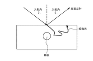
実施例の説明に先立って、反射光を用いた生体認証について説明する。一例として、静脈認証について説明する。静脈認証では、近赤外線の照明を使って皮下の静脈を撮影することによって認証する方式を採用している。図1を参照して、皮膚に照射された光は、拡散光および表面反射光の2種類の反射成分に分離する。 Prior to the description of the embodiment, biometric authentication using reflected light will be described. As an example, vein authentication will be described. In vein authentication, a method is used in which authentication is performed by photographing a subcutaneous vein using near-infrared illumination. Referring to FIG. 1, the light irradiated on the skin is separated into two types of reflection components, diffused light and surface reflected light.
拡散光は、皮下まで透過して拡散しながら通ってきた光である。つまり、拡散光は、皮下に入った光が散乱を繰り返しながら最終的に皮膚表面に到達して出力されたものである。拡散光は、皮下の静脈の情報を含んでおり、静脈認証において有効な反射光として用いられる。 The diffused light is light that has passed through the skin while diffusing. That is, the diffused light is the light that has entered the skin and finally reaches the skin surface while being repeatedly scattered, and is output. The diffused light includes information on the subcutaneous vein and is used as reflected light that is effective in vein authentication.
表面反射光は、空気の屈折率と皮膚の屈折率との違いによって、空気と皮膚との境界面で一定の割合で発生する反射光である。表面反射光の反射方向および強度は、光の入射角度および屈折率(空気および生体の屈折率)によって決まる(スネルの法則/フレネルの法則)。被写体の表面が平らな場合には、表面反射光は、入射角(θ1)と等しい反射角(θ2)方向にのみ得られる。しかしながら、生体のように表面が平らではない被写体の場合、表面反射光はある程度広がった範囲に観測される。表面反射光は、静脈画像にとっては不要なノイズである。 The surface reflected light is reflected light that is generated at a constant rate at the interface between the air and the skin due to the difference between the refractive index of air and the refractive index of the skin. The reflection direction and intensity of the surface reflected light are determined by the incident angle of light and the refractive index (the refractive index of air and the living body) (Snel's law / Fresnel's law). When the surface of the subject is flat, the surface reflected light is obtained only in the direction of the reflection angle (θ2) equal to the incident angle (θ1). However, in the case of a subject whose surface is not flat, such as a living body, the surface reflected light is observed within a certain range. The surface reflected light is unnecessary noise for the vein image.
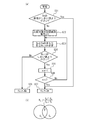
表面反射の反射角は、被写体に対する入射角度に依存する。したがって、手のひらのように凹凸が存在する被写体の場合、光の当たりかたに依存して、表面反射が多く発生する領域(以下、表面反射領域)が発生する場合がある。表面反射領域は、被写体の距離、位置、角度などに依存して決定されるため、図2(a)〜図2(c)のように、手のひらの様々な領域で発生し得る。図2(a)〜図2(c)の例では、網掛けの部分が表面反射領域である。表面反射領域においては、鮮明な静脈画像を撮影することが困難である。表面の模様(皺、傷など)が静脈に重なるためである。この場合、認証精度が低下するおそれがある。 The reflection angle of the surface reflection depends on the incident angle with respect to the subject. Therefore, in the case of a subject having unevenness such as a palm, an area where surface reflection occurs frequently (hereinafter referred to as a surface reflection area) may occur depending on how the light hits. Since the surface reflection area is determined depending on the distance, position, angle, etc. of the subject, it can occur in various areas of the palm as shown in FIGS. 2 (a) to 2 (c). In the example of FIGS. 2A to 2C, the shaded portion is the surface reflection region. In the surface reflection region, it is difficult to capture a clear vein image. This is because surface patterns (such as wrinkles and scratches) overlap the veins. In this case, there is a possibility that the authentication accuracy is lowered.
表面反射を除去する撮影方式として、以下のような技術を用いることができる。例えば、偏光フィルタを用いて表面反射を除去することが考えられる。偏光フィルタは、光をP波とS派とに分離するフィルタである。この偏光フィルタを用いることによって、P波とS波との反射率の違いを利用して表面反射を除去することができる。しかしながら、偏光フィルタは高価であるという問題がある。特に近赤外の波長に対応している品は少なく、より高価となる。また、偏光フィルタを通して自照明を出射する必要がある為、一般には出射光量が半分未満に低下するという問題も生じ得る。 The following techniques can be used as an imaging method for removing surface reflection. For example, it is conceivable to remove surface reflection using a polarizing filter. The polarizing filter is a filter that separates light into a P wave and an S group. By using this polarizing filter, surface reflection can be removed by utilizing the difference in reflectance between the P wave and the S wave. However, there is a problem that the polarizing filter is expensive. In particular, there are few products that support near-infrared wavelengths and they are more expensive. Further, since it is necessary to emit the self-illumination through the polarizing filter, there is a problem that the amount of emitted light is generally reduced to less than half.
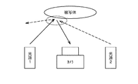
また、表面反射の反射方向は光の入射角に応じて決まるため、複数の照明があった場合に照明の位置に応じて表面反射の発生位置が変わる。そこで、複数照明のオンおよびオフを個別に制御しながら画像を撮影することによって、表面反射成分を除去した画像を生成することができる。しかしながら、この方法を利用すると、装置が大型化してしまう。つまり、図3を参照して、表面反射の入射角に差を付けるために光源を複数箇所に配置すると、一定のスペースが必要になるのである。 In addition, since the reflection direction of the surface reflection is determined according to the incident angle of light, the occurrence position of the surface reflection varies depending on the position of the illumination when there are a plurality of illuminations. Therefore, an image from which the surface reflection component is removed can be generated by taking an image while individually controlling the on / off of the plurality of illuminations. However, when this method is used, the apparatus becomes large. That is, referring to FIG. 3, a certain space is required when the light sources are arranged at a plurality of locations in order to make a difference in the incident angle of the surface reflection.
以下の実施例においては、図面を参照しつつ、装置サイズおよびコストを抑制しつつ認証精度を向上させることができる、生体情報処理装置、生体情報処理方法、および生体情報処理プログラムについて説明する。 In the following embodiments, a biometric information processing apparatus, a biometric information processing method, and a biometric information processing program that can improve authentication accuracy while suppressing apparatus size and cost will be described with reference to the drawings.
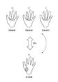
まず、概要について説明する。図4(a)〜図4(c)は、複数の登録画像1〜3を説明するための図である。図4(d)は、照合画像を説明するための図である。登録画像は、事前にデータベースに登録されている特定のユーザの生体画像である。照合画像は、生体センサを介して得られた当該ユーザの生体の画像から得られた照合用の生体画像である。なお、図4(a)〜図4(d)の例は手のひらの輪郭まで含まれる画像であるが、登録される情報および照合用に用いられる情報は、生体の特徴量などのデータであってもよい。
First, an outline will be described. FIG. 4A to FIG. 4C are diagrams for explaining a plurality of registered
生体センサが取得する画像を基に複数の画像を登録する場合、生体と生体センサとの位置関係に大きな変化が無ければ、複数の登録画像1〜3に対して同一の表面反射領域が存在する可能性がある。例えば、複数の画像を撮影する際の時間的間隔が短い場合、複数の画像における生体の姿勢(距離、位置、角度など)は類似していることが多い。この場合、図4(a)〜図4(c)を参照して、登録画像1〜3においてほとんど同じ位置に表面反射領域が生じることになる。一方で、照合の際には、生体の姿勢が登録時と異なっていることが多い。その結果、図4(d)を参照して、表面反射領域の位置が、登録画像1〜3と大きくことなることになる。この場合、互いに表面反射領域の位置が異なった登録画像と照合画像とを比較することになる。表面反射領域においては、登録画像および照合画像の双方において静脈画像の鮮明度が低下しているため、両者共通で鮮明な静脈画像が得られる領域が狭くなる。その結果、登録画像のユーザと照合画像のユーザが同一であったとしても、登録画像と照合画像との類似度が低下するおそれがある。
When a plurality of images are registered based on images acquired by the biological sensor, the same surface reflection region exists for the plurality of registered
これに対して、以下の実施例では、画像登録時に表面反射領域を検出し、複数の登録画像における表面反射領域の重なり具合をチェックする事により、異なった表面反射領域を持つ画像を登録しておく。この場合、照合画像として、様々な位置に表面反射領域が存在する画像が取得された場合においても、認証精度が向上する効果が得られる。 On the other hand, in the following embodiments, an image having different surface reflection areas is registered by detecting the surface reflection area at the time of image registration and checking the overlapping state of the surface reflection areas in a plurality of registered images. deep. In this case, even when images having surface reflection regions at various positions are acquired as verification images, the effect of improving the authentication accuracy can be obtained.
具体的には、図5(a)〜図5(c)の例では、3枚の登録画像1〜3で、表面反射領域の位置が異なっている。図5(d)の照合画像が得られた場合、照合画像と登録画像1,2との間で、表面反射領域が異なった画像同士の照合処理が行われる。その結果、高い類似度は得られない可能性がある。しかしながら、照合画像と登録画像3との間では、ほぼ同じ領域に表面反射領域が位置する。この場合、登録画像と照合画像との間で、表面反射領域が存在する合計の領域が狭くなる。つまり、登録画像と照合画像との間で、表面反射領域が存在しない領域を広くすることができる。この場合、両者共通で鮮明な静脈画像が得られる領域が広くなるため、認証精度が向上する。また、偏光フィルタなどの高価な装置を用いなくてもよいため、コストを抑制することができる。さらに、光源の配置の自由度などが制限されないため、装置サイズを抑制することができる。続いて、以上の概要に沿った実施例について説明する。
Specifically, in the example of FIGS. 5A to 5C, the position of the surface reflection region is different in the three registered
図6(a)は、実施例1に係る生体情報処理装置100のハードウェア構成を説明するためのブロック図である。図6(a)を参照して、生体情報処理装置100は、CPU101、RAM102、記憶装置103、生体センサ104、表示装置105などを備える。これらの各機器は、バスなどによって接続されている。
FIG. 6A is a block diagram for explaining a hardware configuration of the biological
CPU(Central Processing Unit)101は、中央演算処理装置である。CPU101は、1以上のコアを含む。RAM(Random Access Memory)102は、CPU101が実行するプログラム、CPU101が処理するデータなどを一時的に記憶する揮発性メモリである。
A CPU (Central Processing Unit) 101 is a central processing unit. The
記憶装置103は、不揮発性記憶装置である。記憶装置103として、例えば、ROM(Read Only Memory)、フラッシュメモリなどのソリッド・ステート・ドライブ(SSD)、ハードディスクドライブに駆動されるハードディスクなどを用いることができる。記憶装置103は、生体情報処理プログラムを記憶している。表示装置105は、生体情報取得装置100による各処理の結果などを表示するための装置である。表示装置105は、例えば、液晶ディスプレイなどである。
The
生体センサ104は、ユーザの生体画像を取得するセンサであり、ユーザの指、手のひら等の静脈情報を取得する。一例として、生体センサ104は、人体への透過性が高い近赤外線を用いて手のひらの皮下の静脈を撮影する撮影装置である。生体センサ104には、たとえばCMOS(Complementary Metal Oxide Semiconductor)カメラなどが備わっている。また、近赤外線を含む光を照射する照明などが設けられていてもよい。また、生体センサ104は、生体センサ104と生体との距離、該生体の傾きを取得するための距離センサを備えていてもよい。本実施例においては、生体センサ104は、一例として手のひらの画像を撮影することによって、静脈情報を取得する。
The
図6(b)は、生体センサ104の一例を説明するための斜視図である。図6(b)を参照して、生体センサ104は、撮影装置106、光照射部107、および距離センサ108を備える。撮影装置106は、静脈画像を取得できるものであれば特に限定されるものではない。光照射部107は、近赤外線を含む光を照射できるものであれば特に限定されるものではない。また、光照射部107は、複数設けられていてもよい。図6(b)の例では、撮影装置106を囲むように、4つの光照射部107が配置されている。距離センサ108は、被写体との距離を取得できるものであれば特に限定されるものではない。また、距離センサ108は、複数設けられていてもよい。図6(b)の例では、距離センサ108は、各光照射部107の間に配置されている。
FIG. 6B is a perspective view for explaining an example of the
続いて、生体情報処理装置100の各処理について説明する。生体情報処理装置100の記憶装置103に記憶されている生体情報処理プログラムは、実行可能にRAM102に展開される。CPU101は、RAM102に展開された生体情報処理プログラムを実行する。それにより、生体情報取得装置100による各処理が実行される。
Next, each process of the biological
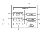
図7は、生体情報処理プログラムの実行によって実現される各機能のブロック図である。図7を参照して、生体情報処理プログラムの実行によって、全体制御部10、撮影部20、表面反射領域検出部30、表面反射領域チェック部40、誘導部50、および認証処理部60が実現される。登録データベース70は、記憶装置103に記憶されている。
FIG. 7 is a block diagram of each function realized by executing the biological information processing program. Referring to FIG. 7,
全体制御部10は、撮影部20、表面反射領域検出部30、表面反射領域検チェック40、誘導部50、および認証処理部60を制御する。撮影部20は、全体制御部10の指示に従って、生体センサ104から手のひらの画像を取得することによって、手のひらの静脈情報を抽出する。表面反射領域検出部30は、生体センサ104が取得した手のひら画像から表面反射領域を検出する。表面反射領域チェック部40は、表面反射領域の位置をチェックする。誘導部50は、ユーザに対し生体を誘導する処理を行う。認証処理部60は、全体制御部10の指示に従って、認証処理を行う。
The
登録処理においては、撮影部20、表面反射領域検出部30、表面反射領域チェック部40、および誘導部50の処理を介して得られたデータは、登録データベース70に登録データとして登録される。認証処理においては、認証処理部60は、撮影部20、表面反射領域検出部30、および表面反射領域チェック部40の処理を介して得られたデータ(照合データ)と登録データベース70に登録されている登録データとを照合する。以下、登録処理および認証処理の詳細について説明する。
In the registration process, data obtained through the processes of the
(登録処理)
図8は、登録処理の際に実行されるフローチャートの一例である。以下、図8を参照しつつ、登録処理の一例について説明する。まず、全体制御部10は、現在の登録枚数nに「1」を代入する(ステップS1)。次に、生体センサ104は、撮影部20の指示に従って、画像Inを撮影する(ステップS2)。本実施例においては、画像Inは、手のひらを被写体とする生体画像であり、登録対象ユーザのn個目の登録データを作成する際に取得される生体画像である。画像取得の際には、被写体に撮影条件が設定されていてもよい。具体的には、被写体までの距離、位置、傾きなどが所定の範囲内に入っている場合にのみ、画像を取得してもよい。なお、被写体までの距離は、距離センサ108を用いることによって測定することができる。被写体の位置は、取得された画像を用いて測定することができる。被写体の傾きは、複数の距離センサ108を用いることによって測定することができる。
(registration process)
FIG. 8 is an example of a flowchart executed during the registration process. Hereinafter, an example of the registration process will be described with reference to FIG. First, the
撮影部20は、生体センサ104が取得した画像Inから手のひら領域を検出する。具体的には、撮影部20は、撮影した手のひら画像の輝度値に対して所定のしきい値で2値化することによって手のひら領域を切り出す。この際、照明の不均一を改善する為に輝度値の正規化処理を加えてもよい。正規化処理を実施することによって、複数の異なった画像における表面反射領域の重なりを簡単にチェックできるようになる。
The
正規化処理を加える場合には、撮影部20は、2値化による手のひら領域の検出後、ラベリング処理を適用することによって、当該領域の面積Aを求める。なお、面積Aが所定のしきい値よりも小さい領域は、ノイズとして処理から取り除いてもよい。撮影部20は、手のひら領域の抽出後、手のひら領域の面積Aに対して正規化を実施する。具体的な正規化処理の方針として下記2つが存在する。
In the case of applying the normalization process, the
まず、手のひら領域の面積Aを所定の大きさA0に正規化する構成とすることができる。子供が成長して手が大きくなったような場合でも静脈パターン自体はほとんど変化しないことから、手のひら領域の面積AをA0に正規化することによって、正しく認証することができる。具体的には、検出した手のひら領域の面積Aが、所定の面積A0になるように変換係数α=√(A0/A)を用いて画像を拡大または縮小処理する。上記係数は、(A0/A)の正の平方根である。 First, it can be configured to normalize the area A of the palm region to a predetermined size A 0. Since the child is hardly changed vein pattern itself even when grown as hand is increased, by normalizing the area A of the palm area A 0, it can be correctly authenticated. Specifically, the image is enlarged or reduced using the conversion coefficient α = √ (A 0 / A) so that the detected area A of the palm region becomes a predetermined area A 0 . The coefficient is the positive square root of (A 0 / A).
あるいは、距離センサ108の測定値を利用し、撮影した画像を所定の距離における画像に換算してもよい。つまり、距離センサ108で測定される距離が距離Dである場合に撮影された画像データを、所定の距離D0(例えば5cm)で撮影した場合の大きさになるように変換する。これは、複数の距離Dに対する変換係数αを事前に測定しておくことによって実現できる。この正規化処理によって、距離の違いによる見かけの手の大きさに依存することなく、表面反射領域の重なりを簡単に比較することができる。この方式では子供の手の成長などに対応ことは困難であるが、所定の距離Dに変換することによって手の大きさ情報を認証処理に加えることが出来ることから、認証精度は高くなる。ユーザが大人に限定されている場合などに特に有効な方式である。
Or you may convert the image | photographed image into the image in predetermined distance using the measured value of the
また、正規化処理の1つとして、手のひらの傾きを補正する処理を加えてもよい。傾きを補正することにより、認証精度向上の効果と合わせて、表面反射領域の重なりチェックをより正確に行うことができるようになる。例えば、特許文献3,4に記載の方式を適用することができる。
Further, as one of the normalization processes, a process of correcting the palm inclination may be added. By correcting the inclination, it is possible to more accurately check the overlap of the surface reflection areas together with the effect of improving the authentication accuracy. For example, the methods described in
次に、表面反射領域検出部30は、画像Inに含まれる表面反射領域Snを算出する(ステップS3)。表面反射領域Snは、表面反射成分が比較的多く現れる領域である。表面反射領域においては、輝度値が高くなる傾向がある。また、表面反射領域においては、皺などの影響により、高周波成分が多く含まれる傾向がある。したがって、高周波成分の割合および輝度値の少なくともいずれか一方が所定のしきい値を上回っている領域を、表面反射領域と定義することができる。本実施例においては、一例として、高周波成分の割合および輝度値の両方が所定のしきい値を上回っている領域を、表面反射領域と定義し、表面反射領域と判断された小領域Ei全体の集合を表面反射領域Sと定義する。また、画像Inにおける表面反射領域をSnと定義する。
Next, the surface reflection
図9は、表面反射領域Snを算出する際に表面反射領域検出部30が実行するフローチャートの一例である。図9を参照して、表面反射領域検出部30は、ステップS2で得られた手のひら領域を複数の小ブロックに分割する(ステップS21)。次に、表面反射領域検出部30は、i番目の小ブロックEi(iは1〜分割数までの整数)の輝度値がしきい値T1よりも高いか否かを判定する(ステップS22)。しきい値T1は、小ブロックEiが表面反射領域であるか否かを判定するための値である。
FIG. 9 is an example of a flowchart executed by the surface reflection
ステップS22において「Yes」と判定された場合、表面反射領域検出部30は、当該小ブロックEiの高周波成分がしきい値T2よりも多いか否かを判定する(ステップS23)。しきい値T2は、小ブロックEiが表面反射領域であるか否かを判定するための値である。ステップS23において「Yes」と判定された場合、表面反射領域検出部30は、当該小ブロックEiが表面反射領域であると判定する(ステップS24)。ステップS22またはステップS23において「No」と判定された場合、表面反射領域検出部30は、当該小ブロックEiが表面反射領域ではないと判定する。以上のステップS22〜ステップS25を各小ブロックに対して実施することによって、手のひら領域における表面反射領域Snを検出することができる。
If it is determined as "Yes" in step S22, surface reflection
再度、図8を参照して、全体制御部10は、登録枚数nが1であるか否かを判定する(ステップS4)。ステップS4において「Yes」と判定された場合、撮影部20は、画像Inから特徴データFnを抽出する(ステップS5)。本実施例においては、特徴データとは、手のひらの静脈パターンをデータとして表したものである。特徴データFnは、画像Inから得られる特徴データである。
Referring to FIG. 8 again,
次に、撮影部20は、特徴データFnを登録データベース70に登録する(ステップS6)。次に、全体制御部10は、登録枚数nが「N」に達したか否かを判定する(ステップS7)。ステップS7で「Yes」と判定された場合、フローチャートの実行が終了する。ステップS7で「No」と判定された場合に、全体制御部10は、登録枚数nの値を1だけ増加させる。「N」はあらかじめ設定されている合計登録枚数であり、例えば、N=3,N=5などである。
Next, the
なお、被写体と生体センサ104との距離、生体センサ104に対する被写体の位置、生体センサ104に対する被写体の傾きなどに撮影条件を設定してもよい。2枚目以降の画像に対しては後述する表面反射領域チェック処理が実施されるため、自由度が低下してしまう。そのため、1枚目の画像I1に対して可能な限り良好な条件を設定することによって、認証精度を向上させてもよい。したがって、1枚目の画像I1の撮影条件を2枚目以降の画像の撮影条件よりも厳しくしてもよい。例えば、上記距離の範囲を通常は5cm±1cmとしているところを、1枚目に限っては5cm±0.5cmのようにより厳しい条件を設定してもよい。
Note that the imaging condition may be set based on the distance between the subject and the
ステップS4で「No」と判定された場合、表面反射領域チェック部40は、表面反射領域Snをチェックする(ステップS9)。図10(a)は、ステップS9が実行される際に、表面反射領域チェック部40が実行するフローチャートの一例である。図10(a)を参照して、表面反射領域チェック部40は、表面反射領域Snの面積がしきい値よりも小さいか否かを判定する(ステップS31)。この場合のしきい値は、表面反射領域Snの面積が大きいか否かを判定するために設定さている。画像Inに対する表面反射の影響が小さい場合には、特段の処理を行わなくても登録データとして用いることができるからである。ステップS31において「No」と判定された場合、表面反射領域チェック部40は、比較対象の登録画像番号mに「1」を代入する(ステップS32)。
When it is determined as “No” in Step S4, the surface reflection
次に、表面反射領域チェック部40は、表面反射領域Snと表面反射領域Smとの重なり割合Rn,mを算出する(ステップS33)。図10(b)を参照して、重なり割合Rn,mは、表面反射領域Snと表面反射領域Smとの和集合(Sn∪Sm)に対する、積集合(Sn∩Sm)の割合である。次に、表面反射領域チェック部40は、重なり割合Rn,mがしきい値よりも小さいか否かを判定する(ステップS34)。この場合のしきい値は、表面反射領域Snの位置と表面反射領域Smの位置を異ならせるために設定される。
Next, the surface reflection
ステップS34において「Yes」と判定された場合、表面反射領域チェック部40は、登録画像番号mを1だけ増加させる(ステップS35)。次に、表面反射領域チェック部40は、登録画像番号mが登録枚数nに達したか否かを判定する(ステップS36)。ステップS36において「No」と判定された場合、ステップS33から再度実行される。
When it determines with "Yes" in step S34, the surface reflection area | region check
ステップS34において「No」と判定された場合、表面反射領域チェック部40は、チェックはNGであると判定する(ステップS38)。ステップS31で「Yes」と判定された場合またはステップS36で「No」と判定された場合、表面反射領域チェック部40は、チェックはOKであると判定する(ステップS37)。
When it determines with "No" in step S34, the surface reflection area | region check
再度、図8を参照して、全体制御部10は、表面反射領域のチェックがOKであるか否かを判定する(ステップS10)。ステップS10において「Yes」と判定された場合には、ステップS5が実行される。ステップS10において「No」と判定された場合には、誘導部50は誘導処理を行う(ステップS11)。ステップS11の実行後、ステップS2が実行される。
Referring to FIG. 8 again,
誘導部50は、距離に基づく誘導、位置に基づく誘導などを行う。例えば、図11を参照して、誘導部50は、登録データを得た際の生体センサ104と被写体との距離と異なるように、被写体の位置を誘導する。例えば、登録データを得た際の距離がDi(i=1,・・・(n−1))であった場合、図12を参照して、誘導部50は、登録可能な範囲の距離(Dmin〜Dmax)に対して、“距離Diまでの距離の最小値”を計算する。図12の例では、当該最小値が最大となる位置が新たに誘導すべき適切な距離である。例えば、Dminは4cm程度であり、Dmaxは6cm程度である。
The
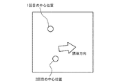
位置の誘導では、図13を参照して、誘導部50は、登録データを得た際の位置とは異なる位置に被写体を誘導する。具体的には、誘導部50は、手のひら領域の中心座標(=手のひら領域の重心座標)を記録しておき、中心座標同士が遠くなるように誘導処理を行う。上記の距離の誘導を行った場合と同様の処理を2次元画像に対して行い(位置座標(x,y))、誘導方向を決定してもよい。これは、画像処理の分野で一般的に“距離変換”と呼ばれる方式を応用したものである。なお、距離変換とは、画像処理の分野で用いられる手法であり、距離変換における背景を登録済み画像の位置と置き換えて処理する変換方式である。
In the position guidance, referring to FIG. 13, the guiding
なお、誘導部50は、画像、音声などのメッセージをユーザに発することによって、当該ユーザを誘導する。例えば、誘導部50は、表示装置105に誘導位置を表示することによって、当該ユーザを誘導してもよい。
The guiding
なお、生体センサ104に対する被写体の傾きを変えることによって表面反射領域を変えるように誘導することも可能である。被写体の傾きをユーザに指示して誘導することが困難である場合、被写体の距離または位置を優先して誘導してもよい。
It is also possible to guide the surface reflection area to be changed by changing the inclination of the subject with respect to the
また、距離を誘導する場合と位置を誘導する場合とを比較すると、距離を誘導する場合には被写体に当たる照明分布を均一化させやすいという利点がある。すなわち、照明が当たる際の位置に応じて明暗の影響を回避しやすくなる。したがって、誘導の優先順位として、距離に基づく誘導を行うことによって認証精度を向上させてもよい。距離に基づく誘導では登録済の表面反射領域の位置との違いがあまり出せないと判断された場合に、位置に基づく誘導を行ってもよい。また、位置に基づく誘導では不十分と判断された場合に、被写体の傾きに基づく誘導を行ってもよい。 Further, when comparing the case of guiding the distance and the case of guiding the position, there is an advantage that the distribution of illumination hitting the subject can be easily made uniform when the distance is guided. That is, it becomes easy to avoid the influence of light and dark according to the position at the time of illumination. Therefore, authentication accuracy may be improved by performing guidance based on distance as the priority of guidance. If it is determined that the distance-based guidance is not so different from the registered position of the surface reflection region, guidance based on the position may be performed. Further, when it is determined that the guidance based on the position is insufficient, the guidance based on the inclination of the subject may be performed.
図14は、上記登録処理によって登録データベース70に登録される登録データの一例を説明するためのテーブルである。図14を参照して、「ID」は、登録ユーザを一意に表すための情報である。この「ID」にユーザの姓名や住所などの情報を対応させてもよい。「登録No.」は、登録データに順番に付与される番号であり、上記の登録枚数nに対応する。図14の例では、合計登録枚数N=3である。
FIG. 14 is a table for explaining an example of registration data registered in the
「登録特徴データ」は、認証に使用する為の登録データである。本実施例においては、生体センサ104によって取得された画像から静脈部分を抽出した静脈パターンである。「表面反射領域情報」は、各登録特徴データを取得した際に検出された表面反射領域を表すデータである。具体的には、表面反射を検出する際に用いた小ブロックEiごとに「0」または「1」の値を持つデータである。例えば、「1」が表面反射領域であることを示し、「0」が表面反射領域ではないことを示す。また、各Eiに対する情報を1ビットに割当て、ビット単位で情報を保存してもよい。
“Registration feature data” is registration data for use in authentication. In this embodiment, the vein pattern is obtained by extracting the vein portion from the image acquired by the
「登録時の距離」は、登録特徴データを取得した際の生体センサ104と手のひらとの距離である。図14では、当該距離をcm単位で表してある。「登録時の位置」は、登録特徴データを取得した際の手のひらの中心座標であり、具体的には手のひら領域の重心座標である。座標は、画面の中心を(0,0)とした場合の中心からのズレ量である。「登録時の距離」および「登録時の位置」は、誘導部50による誘導処理の際に用いることができる。なお、「登録時の距離」および「登録時の位置」は、登録データベース70ではなくRAM102に一時的に記憶されていてもよい。
“Distance at the time of registration” is the distance between the
また、上記登録処理の際に取得される画像を総合的に判定してもよい。例えば、登録処理時における重なり割合R、距離D、被写体の位置X、および被写体の傾きθに応じて、登録処理を進めるか否かを判断してもよい。被写体の位置Xは、手のひら領域の中心座標(重心座標)である。被写体の傾きθは、生体センサ104の上面に対する被写体の傾斜角度のことである。例えば、下記式(1)で表される登録スコアScを算出してもよい。
Sc(n)=a0×R+a1×ΔD+a2×ΔX+a3×Δθ (式1)
Moreover, you may determine comprehensively the image acquired in the case of the said registration process. For example, whether or not to proceed with the registration process may be determined according to the overlap ratio R, distance D, subject position X, and subject inclination θ during the registration process. The subject position X is the center coordinate (centroid coordinate) of the palm region. The subject inclination θ is an inclination angle of the subject with respect to the upper surface of the
Sc (n) = a 0 × R + a 1 × ΔD + a 2 × ΔX + a 3 × Δθ (Formula 1)
ここでSc(n)は、n枚目の画像に対するスコアScを表している。Rは、表面反射領域が登録済のものと重なっている割合を表す。例えば、1枚目の画像の場合、登録済の画像は存在しないため、R=0.0である。一方、3枚目の画像を考えた場合、現在(n=3)の画像の表面反射領域S3に対して、登録済の表面反射領域S1,S2が重なっている割合をRとする。Rは、下記式(2)で表される。この場合、Rが小さい方が望ましい登録画像となる。
R=S3∩(S1∪S2)/S3∪(S1∪S2) (式2)
Here, Sc (n) represents the score Sc for the nth image. R represents the ratio at which the surface reflection region overlaps the registered one. For example, in the case of the first image, R = 0.0 because there is no registered image. On the other hand, when the third image is considered, R is the ratio of the registered surface reflection areas S 1 and S 2 overlapping the surface reflection area S 3 of the current (n = 3) image. . R is represented by the following formula (2). In this case, a smaller registered R is a desirable registered image.
R = S 3 ∩ (S 1 ∪S 2 ) / S 3 ∪ (S 1 ∪S 2 ) (Formula 2)
また、ΔDは、距離センサ108で取得した距離Dと所定の距離D0(望ましい距離)との差の絶対値を表す。ΔDの値が小さい方が望ましい登録画像である。ΔXは、手のひらの位置(座標)Xと手のひらの適切な位置との距離を表す量である。ΔXが小さい方が望ましい登録画像である。Δθも同様である。手のひらの傾きθと手のひらの適切な傾き(例えば0度)との差の絶対値を表す量で、Δθが小さい方が望ましい登録画像である。
ΔD represents the absolute value of the difference between the distance D acquired by the
(式1)の係数a0〜a3は、各値に対するウェイトを表しており、これらの値を調整することで、適切な判断を行う事ができるようになる。例えば、係数a0〜a3をプラスの値に設定すると、(式1)の登録スコアSc(n)が小さい方が望ましい登録画像であると判断できる。 Coefficients a 0 to a 3 in (Equation 1) represent weights for the respective values, and appropriate judgment can be made by adjusting these values. For example, if the coefficients a 0 to a 3 are set to positive values, it can be determined that a registered image with a smaller registration score Sc (n) in (Equation 1) is desirable.
係数a0〜a3の具体的な値は次のように設定してもよい。まず、各値(R,ΔD,ΔX,Δθ)ごとに変動範囲が異なることから、各々の値を正規化する項を含める形で係数を記述する。まず、Rはもともと割合を表す値(表面反射領域が重なっている割合)であって、0.0〜1.0の範囲を取る正規化された値である。そこで、a0=W0と設定することができる。ここで、W0は、該当パラメータの重要度を表す係数である。一方、ΔDは、距離のずれの絶対値を表す値である。そのため、ΔDに対しては、a1=W1/D0と設定することができる。つまり、所定の距離D0に対する誤差の割合に重要度を表す係数W1を掛ける形で係数a1を設定する。 Specific values of the coefficients a 0 to a 3 may be set as follows. First, since the variation range is different for each value (R, ΔD, ΔX, Δθ), the coefficient is described so as to include a term for normalizing each value. First, R is a value that originally represents a ratio (a ratio in which the surface reflection regions overlap), and is a normalized value that takes a range of 0.0 to 1.0. Therefore, a 0 = W 0 can be set. Here, W 0 is a coefficient representing the importance of the corresponding parameter. On the other hand, ΔD is a value representing the absolute value of the distance shift. Therefore, it is possible to set a 1 = W 1 / D 0 for ΔD. That is, the coefficient a 1 is set by multiplying the ratio of the error with respect to the predetermined distance D 0 by the coefficient W 1 representing importance.
係数a2に対しても同様で、a2=W2/Xmaxのように設定することができる。ここで、XmaxはΔXの取り得る最大値で、例えば画面の解像度が480ピクセルであった場合には、Xmax=240である。係数a3に対しても同様で、a3=W3/θmaxのように設定することができる。ここで、θの単位を度(degree)とすると、θは−180度〜+180度の範囲で変動する。したがって、θmax=180度である。 The same applies to the coefficient a 2 , and it can be set as a 2 = W 2 / X max . Here, X max is the maximum value that can be taken by ΔX. For example, when the screen resolution is 480 pixels, X max = 240. The same applies to the coefficient a 3 , and it can be set as a 3 = W 3 / θ max . Here, if the unit of θ is degrees, θ varies in the range of −180 degrees to +180 degrees. Therefore, θ max = 180 degrees.
W0〜W3は、各々のパラメータが認証に対して持つ重要度に応じて設定するものである。したがって、例えば、W0=0.6、W1=0.1、W2=0.1、W3=0.2といった値に設定することができる。この例では、距離や位置の変動は認証において比較的簡単に対応できるのに対して表面反射や傾きは対応が難しいため、表面反射や傾きのウェイトを大きくしている。特に表面反射に関しては画像処理で影響を完全に除くことは困難である為、他のパラメータよりもウェイトを大きく設定する。 W 0 to W 3 are set according to the importance of each parameter for authentication. Therefore, for example, values such as W 0 = 0.6, W 1 = 0.1, W 2 = 0.1, and W 3 = 0.2 can be set. In this example, variations in distance and position can be dealt with relatively easily in authentication, but surface reflection and inclination are difficult to deal with, so the weight of surface reflection and inclination is increased. In particular, with respect to surface reflection, it is difficult to completely remove the influence by image processing, so the weight is set larger than other parameters.
誘導方法の1つとして、表面反射領域検出部30が検出した表面反射領域を表示装置105に表示することによって、ユーザに自主的に手のひらを移動させてもよい。この際、登録済みの表面反射領域を表示装置105に表示することによって、登録済の表面反射領域内に表面反射領域が発生しないようにユーザに自主的に調整させてもよい。
As one of the guiding methods, the user may voluntarily move the palm by displaying the surface reflection area detected by the surface reflection
(認証処理)
図15は、認証処理の際に実行されるフローチャートの一例である。認証処理は、例えば、PC起動時のBIOS認証、OSのログオン認証の際に実施される。まず、生体センサ104は、撮影部20の指示に従って、認証用の画像Iを撮影する(ステップS41)。次に、撮影部20は、画像Iから照合用特徴データを生成する(ステップS42)。ここで、照合用特徴データは、画像Iから静脈に関する特徴量(静脈パターンなど)を抽出することによって生成することができる。
(Authentication process)
FIG. 15 is an example of a flowchart executed in the authentication process. The authentication process is performed, for example, at the time of BIOS authentication at the time of starting the PC, or logon authentication of the OS. First, the
次に、認証処理部60は、照合用特徴データと、登録データベース70に登録されている登録特徴データとの照合を行う(ステップS43)。次に、認証処理部60は、照合用特徴データと各登録特徴データとの類似度を算出する。この際、認証処理部60は、いずれか1つ以上の登録特徴データを選択した上で類似度を算出する。本実施例においては、静脈パターンの類似度(一致度)が算出される。次に、認証処理部60は、算出された類似度が所定のしきい値以上となる登録特徴データが発見されたか否かを判定する(ステップS44)。ステップS44で「Yes」と判定された場合、認証処理部60は、被認証ユーザが当該登録特徴データに係るユーザであると特定し(認証成功)、当該特定結果を出力する(ステップS45)。ステップS44において「No」と判定された場合、認証処理部60は、認証失敗の結果を出力する(ステップS46)。
Next, the
なお、照合処理の際に照合用に取得された画像から検出された表面反射領域が類似している登録特徴データを選択し、当該登録特徴データと照合用特徴データとの類似度を優先的に算出することによって認証精度を向上させることができる。また、表面反射領域の重なり割合に応じて類似度や類似度の信頼性を調整してもよい。このようにする事によって認証精度を向上させることができる。例えば、n番目の登録テンプレートとのマッチング結果の類似度Sim(n)を考える。照合用に取得された画像の表面反射領域をSI、n番目の登録テンプレートの表面反射領域をSnとする。この場合、下記RI(n)を計算する
RI(n)=(SI∩Sn)/(SI∪Sn) (式3)
It is to be noted that registered feature data having similar surface reflection areas detected from images acquired for matching during the matching process is selected, and the similarity between the registered feature data and the matching feature data is given priority. By calculating, the authentication accuracy can be improved. Further, the similarity and the reliability of the similarity may be adjusted according to the overlapping ratio of the surface reflection regions. By doing so, the authentication accuracy can be improved. For example, consider the similarity Sim (n) of the matching result with the nth registered template. Let S I be the surface reflection area of the image acquired for verification, and Sn be the surface reflection area of the nth registered template. In this case, the following R I (n) is calculated R I (n) = (S I ∩Sn) / (S I ∪Sn) (Formula 3)
RI(n)は、n番目の登録特徴データと照合用特徴データの表面反射領域とがどの程度共通しているかを表す量である。RI(n)が大きい方が類似度の信頼性が高いと判断できる。この結果を利用して計算した類似度Sim(n)に補正を行ってもよい。ここでf(x)は、補正を行う為の関数で、例えばf(x)=xとしてもよい。
Sim(n)´=Sim(n)×f(RI(n)) (式4)
R I (n) is an amount representing how common the n-th registered feature data and the surface reflection region of the matching feature data are. It can be judged that the reliability of similarity is higher when R I (n) is larger. You may correct | amend to similarity Sim (n) calculated using this result. Here, f (x) is a function for performing correction, and may be f (x) = x, for example.
Sim (n) ′ = Sim (n) × f (R I (n)) (Formula 4)
また、上記照合処理の際に、ブロックマッチングを適用してもよい。ブロックマッチングとは、登録特徴データおよび照合用特徴データを空間的に複数のブロックに分割し、ブロック単位でマッチング(照合)する方法である。ブロック単位で照合することによって、手のひらの微小な変形などに対応できるメリットがある。例えば、親指の広げ方の違いに起因して親指の付け根近辺の領域が僅かに平行移動しているような場合、手のひら全体の平行移動では吸収が困難である。しかしながら、ブロックに分割することでブロックの平行移動として吸収することが可能になる。 Further, block matching may be applied during the collation process. Block matching is a method in which registered feature data and matching feature data are spatially divided into a plurality of blocks and matched (matched) in units of blocks. By collating in block units, there is a merit that it is possible to cope with minute deformations of the palm. For example, when the region near the base of the thumb is slightly translated due to the difference in how to spread the thumb, it is difficult to absorb the entire palm by translation. However, by dividing into blocks, it becomes possible to absorb the parallel movement of the blocks.
ブロックマッチングの場合、ブロック単位で類似度を計算して所定のしきい値を超えたブロックの割合が所定のしきい値を超えているかどうかで、認証を行うことができる。あるいは、全ブロックの内、類似度の高い上位の値のみを判定に用いる構成としてもよい。例えば、ブロックごとの類似度の上位50%のみを用い、その上位50%の類似度の平均値やメディアン値を判定処理に用いる。このようにすると、例えば、指の開き方等の違いなどでどうしても登録と照合で一致させることが困難な領域を排除したマッチング処理を実現する事ができる。 In the case of block matching, authentication can be performed based on whether or not the percentage of blocks that exceed a predetermined threshold by calculating similarity in units of blocks exceeds a predetermined threshold. Or it is good also as a structure which uses only a high value with high similarity among all the blocks for determination. For example, only the top 50% of the similarities for each block are used, and the average value or median value of the top 50% similarity is used for the determination process. In this way, for example, it is possible to realize a matching process that excludes regions that are inevitably difficult to match by registration and collation due to differences in finger opening methods and the like.
本実施例においては、複数の登録画像における表面反射領域が重ならないように登録し、その結果として照合画像と登録画像での表面反射領域の重なりが多い状態でのマッチングを実現できる確率を高めている。この際に上記のブロックマッチングを適用し、上位50%の類似度のみを使用すると、表面反射領域が存在している領域同士のブロックは判定から除外し、表面反射領域が存在しない良好な領域のみを判定に利用する事ができる。以上から、本実施例においてブロックマッチングを適用することによって、認証精度をより高めることができる。 In the present embodiment, registration is performed so that the surface reflection areas in the plurality of registered images do not overlap, and as a result, the probability of realizing matching in a state where there are many overlaps of the surface reflection areas in the verification image and the registration image is increased. Yes. In this case, if the above block matching is applied and only the top 50% similarity is used, the blocks between the areas where the surface reflection areas exist are excluded from the determination, and only the good areas where the surface reflection areas do not exist are excluded. Can be used for judgment. From the above, the authentication accuracy can be further improved by applying block matching in the present embodiment.
なお、図14の登録データでは、1:N認証を対象にしているが、1:1認証を対象にしてもよい。1:N認証とは、N人の登録されたユーザから該当するユーザを特定する認証方式である。1:1認証とは、事前にIDカードなどを使って自分が誰であるかを明示した上で認証を行う方式である。したがって、1人の登録されたユーザと、被認証ユーザが一致するか否かを判定する認証方式である。 In the registration data of FIG. 14, 1: N authentication is targeted, but 1: 1 authentication may be targeted. 1: N authentication is an authentication method for identifying a corresponding user from N registered users. The 1: 1 authentication is a method of performing authentication after clearly indicating who the person is using an ID card or the like in advance. Therefore, this is an authentication method for determining whether one registered user and an authenticated user match.
上記実施例においては、被写体として手のひらを用いているが、指などの他の被写体を撮影することによって、当該被写体の皮下の静脈パターンを生体情報として抽出してもよい。また、上記実施例においては生体として静脈パターンを用いているが、表面反射成分がノイズとして現れる生体であれば、上記実施例を適用することができる。例えば、顔、虹彩などを生体情報として用いてもよい。 In the above embodiment, the palm is used as the subject. However, by photographing another subject such as a finger, the subcutaneous vein pattern of the subject may be extracted as the biological information. Moreover, although the vein pattern is used as the living body in the above embodiment, the above embodiment can be applied as long as the surface reflection component appears as noise. For example, you may use a face, an iris, etc. as biometric information.
上記実施例においては、表面反射領域検出部30が、複数の生体画像の表面反射領域を検出する検出部として機能する。表面反射領域チェック部40および登録データベース70が、互いに表面反射領域が異なる生体画像から得られる生体情報を記憶する記憶部として機能する。表面反射領域チェック部40が、表面反射領域の重なり割合を算出する算出部として機能する。認証処理部60が、選択部として機能するとともに、照合部として機能する。
In the said Example, the surface reflection area |
以上、本発明の実施例について詳述したが、本発明は係る特定の実施例に限定されるものではなく、特許請求の範囲に記載された本発明の要旨の範囲内において、種々の変形・変更が可能である。 Although the embodiments of the present invention have been described in detail above, the present invention is not limited to such specific embodiments, and various modifications and changes can be made within the scope of the gist of the present invention described in the claims. It can be changed.
10 全体制御部
20 撮影部
30 表面反射領域検出部
40 表面反射領域チェック部
50 誘導部
60 認証処理部
70 登録データベース
100 生体情報処理装置
104 生体センサ
105 表示装置
DESCRIPTION OF
Claims (14)
前記複数の生体画像の表面反射領域を検出する検出部と、
前記複数の生体画像のうち、表面反射領域が互いに異なる生体画像から得られる生体情報を記憶する記憶部と、を備えることを特徴とする生体情報処理装置。 A biosensor for acquiring a plurality of biometric images of the user;
A detection unit for detecting a surface reflection region of the plurality of biological images;
A biological information processing apparatus comprising: a storage unit that stores biological information obtained from biological images having different surface reflection areas among the plurality of biological images.
前記記憶部は、前記算出部が算出した重なり割合が所定値以下である場合に、当該生体画像の生体情報を記憶することを特徴とする請求項1〜3のいずれか一項に記載の生体情報処理装置。 A calculation unit that calculates an overlapping ratio of surface reflection regions detected by the detection unit with respect to the plurality of biological images;
The living body according to any one of claims 1 to 3, wherein the storage unit stores biological information of the biological image when the overlapping ratio calculated by the calculation unit is equal to or less than a predetermined value. Information processing device.
前記誘導部は、前記生体を誘導する際に、前記記憶部に記憶された表面反射領域を表示する表示装置を備えることを特徴とする請求項5または6記載の生体情報処理装置。 The storage unit stores a surface reflection region,
The biological information processing apparatus according to claim 5, wherein the guiding unit includes a display device that displays a surface reflection region stored in the storage unit when guiding the living body.
前記選択部が選択した生体情報と、前記生体センサが取得した被認証ユーザの認証用生体画像に係る認証用生体情報とを照合する照合部と、を備えることを特徴とする請求項1〜7のいずれか一項に記載の生体情報処理装置。 A selection unit that selects any one or more of biological information related to a plurality of biological images stored in the storage unit;
The biometric information which the said selection part selected and the collation part which collates the biometric information for authentication which concerns on the biometric image for authentication of the to-be-authenticated user which the said biometric sensor acquired are provided. The biological information processing apparatus according to any one of the above.
前記選択部は、前記認証用生体画像の表面反射領域と、前記記憶部に記憶された表面反射領域との重なり割合に応じて、生体情報を選択することを特徴とする請求項8記載の生体情報処理装置。 The storage unit stores the plurality of biological information in association with a surface reflection region,
The living body according to claim 8, wherein the selection unit selects biological information according to an overlapping ratio between a surface reflection region of the biometric image for authentication and a surface reflection region stored in the storage unit. Information processing device.
前記複数の生体画像の表面反射領域を検出し、
前記複数の生体画像のうち、表面反射領域が互いに異なる生体画像から得られる生体情報を記憶部に記憶する、ことを特徴とする生体情報処理方法。 Using a biometric sensor, obtain multiple user biometric images,
Detecting a surface reflection region of the plurality of biological images;
A biological information processing method, wherein biological information obtained from biological images having different surface reflection areas among the plurality of biological images is stored in a storage unit.
生体センサを用いて、ユーザの複数の生体画像を取得する取得ステップと、
前記複数の生体画像の表面反射領域を検出する検出ステップと、
前記複数の生体画像のうち、表面反射領域が互いに異なる生体画像から得られる生体情報を記憶部に記憶する記憶ステップと、を実行させることを特徴とする生体情報処理プログラム。 On the computer,
An acquisition step of acquiring a plurality of biological images of the user using a biological sensor;
A detection step of detecting a surface reflection region of the plurality of biological images;
And a storage step of storing in a storage unit biological information obtained from biological images having different surface reflection areas among the plurality of biological images.
Priority Applications (3)
| Application Number | Priority Date | Filing Date | Title |
|---|---|---|---|
| JP2011120531A JP5751019B2 (en) | 2011-05-30 | 2011-05-30 | Biological information processing apparatus, biological information processing method, and biological information processing program |
| EP12160725.3A EP2530620B1 (en) | 2011-05-30 | 2012-03-22 | Biometric information process device, biometric information process method, and computer readable medium |
| US13/428,387 US9412014B2 (en) | 2011-05-30 | 2012-03-23 | Biometric information process device, biometric information process method, and computer readable medium |
Applications Claiming Priority (1)
| Application Number | Priority Date | Filing Date | Title |
|---|---|---|---|
| JP2011120531A JP5751019B2 (en) | 2011-05-30 | 2011-05-30 | Biological information processing apparatus, biological information processing method, and biological information processing program |
Publications (2)
| Publication Number | Publication Date |
|---|---|
| JP2012248079A true JP2012248079A (en) | 2012-12-13 |
| JP5751019B2 JP5751019B2 (en) | 2015-07-22 |
Family
ID=45999592
Family Applications (1)
| Application Number | Title | Priority Date | Filing Date |
|---|---|---|---|
| JP2011120531A Active JP5751019B2 (en) | 2011-05-30 | 2011-05-30 | Biological information processing apparatus, biological information processing method, and biological information processing program |
Country Status (3)
| Country | Link |
|---|---|
| US (1) | US9412014B2 (en) |
| EP (1) | EP2530620B1 (en) |
| JP (1) | JP5751019B2 (en) |
Families Citing this family (7)
| Publication number | Priority date | Publication date | Assignee | Title |
|---|---|---|---|---|
| JP5691669B2 (en) * | 2011-03-08 | 2015-04-01 | 富士通株式会社 | Biological information processing apparatus, biological information processing method, and biological information processing program |
| WO2013145168A1 (en) * | 2012-03-28 | 2013-10-03 | 富士通株式会社 | Biometric authentication device, biometric authentication method, and biometric authentication program |
| JP6044403B2 (en) * | 2013-03-18 | 2016-12-14 | 富士通株式会社 | Imaging apparatus, imaging method, and imaging program |
| JP6160148B2 (en) * | 2013-03-19 | 2017-07-12 | 富士通株式会社 | Biological information input device, biometric information input program, and biometric information input method |
| KR101714349B1 (en) * | 2014-12-29 | 2017-03-09 | 주식회사 슈프리마 | Biometric image output-control method and biometric authentification apparatus |
| EP3118762B1 (en) * | 2015-07-15 | 2020-03-11 | Biowatch SA | Method, device and computer program for authenticating a user |
| WO2019235773A1 (en) * | 2018-06-08 | 2019-12-12 | Samsung Electronics Co., Ltd. | Proximity based access control in a communication network |
Citations (9)
| Publication number | Priority date | Publication date | Assignee | Title |
|---|---|---|---|---|
| JPH10162146A (en) * | 1996-11-29 | 1998-06-19 | Oki Electric Ind Co Ltd | Individual discriminating device |
| JP2001167252A (en) * | 1999-12-10 | 2001-06-22 | Oki Electric Ind Co Ltd | Ophthalmic image preparing method, method and device for identifying iris |
| JP2004030564A (en) * | 2002-02-05 | 2004-01-29 | Matsushita Electric Ind Co Ltd | Personal identification method, personal identification apparatus, and photographing device |
| JP2004178134A (en) * | 2002-11-26 | 2004-06-24 | Sony Corp | Fingerprint collating device and fingerprint collating method |
| US20050226467A1 (en) * | 2003-03-07 | 2005-10-13 | Takahiro Hatano | Biological image correlation device and correlation method thereof |
| JP2006287689A (en) * | 2005-04-01 | 2006-10-19 | Matsushita Electric Ind Co Ltd | Image processing method, image processor, image processing program and integrated circuit including the image processor |
| JP2008021072A (en) * | 2006-07-12 | 2008-01-31 | Matsushita Electric Ind Co Ltd | Photographic system, photographic device and collation device using the same, and photographic method |
| JP2010277315A (en) * | 2009-05-28 | 2010-12-09 | Sony Corp | Information processing apparatus, authentication data selection method, and program |
| WO2011061940A1 (en) * | 2009-11-18 | 2011-05-26 | パナソニック株式会社 | Image processing method, and image processing device |
Family Cites Families (14)
| Publication number | Priority date | Publication date | Assignee | Title |
|---|---|---|---|---|
| WO1998008439A1 (en) | 1996-08-25 | 1998-03-05 | Sensar, Inc. | Apparatus for the iris acquiring images |
| US6088470A (en) | 1998-01-27 | 2000-07-11 | Sensar, Inc. | Method and apparatus for removal of bright or dark spots by the fusion of multiple images |
| JP2002112970A (en) | 2000-10-10 | 2002-04-16 | Daito Seiki Co Ltd | Device and method for observing surface of skin |
| JP3877959B2 (en) | 2000-12-28 | 2007-02-07 | 花王株式会社 | Skin color measuring device and skin image processing device |
| JP2002288642A (en) * | 2001-03-27 | 2002-10-04 | Nec Corp | Palm print region dividing device nd method and palm print region dividing program |
| US7081951B2 (en) * | 2003-10-09 | 2006-07-25 | Cross Match Technologies, Inc. | Palm print scanner and methods |
| JP4644540B2 (en) | 2005-06-28 | 2011-03-02 | 富士通株式会社 | Imaging device |
| JP4786483B2 (en) * | 2006-09-14 | 2011-10-05 | 富士通株式会社 | Biometric guidance control method for biometric authentication device and biometric authentication device |
| JP2008225970A (en) | 2007-03-14 | 2008-09-25 | Matsushita Electric Ind Co Ltd | Image synthesizing device, image collation device using the same and image synthesizing method |
| JP4485549B2 (en) | 2007-07-30 | 2010-06-23 | 富士通株式会社 | Imaging device |
| JP2009077930A (en) | 2007-09-26 | 2009-04-16 | Toshiba Corp | Biological information imaging device and personal identification device using it |
| JP4541427B2 (en) * | 2008-03-25 | 2010-09-08 | 富士通株式会社 | Biometric authentication device, biometric information registration device, and biometric authentication method |
| WO2010032126A2 (en) * | 2008-09-22 | 2010-03-25 | Kranthi Kiran Pulluru | A vein pattern recognition based biometric system and methods thereof |
| EP2444933B1 (en) * | 2009-06-17 | 2019-07-10 | Fujitsu Limited | Biometric authentication device, biometric authentication method and computer program for biometric authentication |
-
2011
- 2011-05-30 JP JP2011120531A patent/JP5751019B2/en active Active
-
2012
- 2012-03-22 EP EP12160725.3A patent/EP2530620B1/en active Active
- 2012-03-23 US US13/428,387 patent/US9412014B2/en active Active
Patent Citations (9)
| Publication number | Priority date | Publication date | Assignee | Title |
|---|---|---|---|---|
| JPH10162146A (en) * | 1996-11-29 | 1998-06-19 | Oki Electric Ind Co Ltd | Individual discriminating device |
| JP2001167252A (en) * | 1999-12-10 | 2001-06-22 | Oki Electric Ind Co Ltd | Ophthalmic image preparing method, method and device for identifying iris |
| JP2004030564A (en) * | 2002-02-05 | 2004-01-29 | Matsushita Electric Ind Co Ltd | Personal identification method, personal identification apparatus, and photographing device |
| JP2004178134A (en) * | 2002-11-26 | 2004-06-24 | Sony Corp | Fingerprint collating device and fingerprint collating method |
| US20050226467A1 (en) * | 2003-03-07 | 2005-10-13 | Takahiro Hatano | Biological image correlation device and correlation method thereof |
| JP2006287689A (en) * | 2005-04-01 | 2006-10-19 | Matsushita Electric Ind Co Ltd | Image processing method, image processor, image processing program and integrated circuit including the image processor |
| JP2008021072A (en) * | 2006-07-12 | 2008-01-31 | Matsushita Electric Ind Co Ltd | Photographic system, photographic device and collation device using the same, and photographic method |
| JP2010277315A (en) * | 2009-05-28 | 2010-12-09 | Sony Corp | Information processing apparatus, authentication data selection method, and program |
| WO2011061940A1 (en) * | 2009-11-18 | 2011-05-26 | パナソニック株式会社 | Image processing method, and image processing device |
Also Published As
| Publication number | Publication date |
|---|---|
| EP2530620A1 (en) | 2012-12-05 |
| EP2530620B1 (en) | 2017-10-11 |
| JP5751019B2 (en) | 2015-07-22 |
| US9412014B2 (en) | 2016-08-09 |
| US20120307031A1 (en) | 2012-12-06 |
Similar Documents
| Publication | Publication Date | Title |
|---|---|---|
| JP5751019B2 (en) | Biological information processing apparatus, biological information processing method, and biological information processing program | |
| CN107949863B (en) | Authentication device and authentication method using biometric information | |
| JP7242528B2 (en) | Systems and methods for performing fingerprint user authentication using images captured using mobile devices | |
| JP6650946B2 (en) | System and method for performing fingerprint-based user authentication using images captured with a mobile device | |
| JP5831018B2 (en) | Biometric authentication device and method for adjusting user's hand position in biometric authentication device | |
| JP5504928B2 (en) | Biometric authentication device, biometric authentication method, and program | |
| JP5691669B2 (en) | Biological information processing apparatus, biological information processing method, and biological information processing program | |
| JP5846291B2 (en) | Biometric authentication device, biometric authentication method, and biometric authentication program | |
| WO2012111664A1 (en) | Authentication device, authentication program, and authentication method | |
| JP6467852B2 (en) | Biological information correction apparatus, biological information correction method, and biological information correction computer program | |
| JP4783331B2 (en) | Face recognition device | |
| KR20110063679A (en) | A vein pattern recognition based biometric system and methods thereof | |
| JP6160148B2 (en) | Biological information input device, biometric information input program, and biometric information input method | |
| JP2013045180A (en) | Biometrics authentication apparatus, biometrics authentication method and program | |
| JPWO2010041731A1 (en) | Verification device, verification method, and program | |
| JP2010240215A (en) | Vein depth determination apparatus, vein depth determination method and program | |
| JP4849181B2 (en) | Authentication imaging apparatus, authentication imaging method, and authentication imaging program | |
| JP2017162302A (en) | Biometric authentication device, biometric authentication method, and biometric authentication program | |
| JP6846330B2 (en) | Biometric device and biometric system | |
| JP5768441B2 (en) | Biological information acquisition apparatus, biological information acquisition method, and biological information acquisition program | |
| JP6801434B2 (en) | Bioimage processing device, bioimage processing method and bioimage processing program | |
| JP2018081469A (en) | Blood vessel image pickup apparatus and personal authentication system | |
| JP5685272B2 (en) | Authentication apparatus, authentication program, and authentication method | |
| WO2015056210A2 (en) | Method of authenticating a person | |
| KR20220037473A (en) | Shooting device and authentication device |
Legal Events
| Date | Code | Title | Description |
|---|---|---|---|
| A621 | Written request for application examination |
Free format text: JAPANESE INTERMEDIATE CODE: A621 Effective date: 20140304 |
|
| A977 | Report on retrieval |
Free format text: JAPANESE INTERMEDIATE CODE: A971007 Effective date: 20141127 |
|
| A131 | Notification of reasons for refusal |
Free format text: JAPANESE INTERMEDIATE CODE: A131 Effective date: 20141209 |
|
| A521 | Request for written amendment filed |
Free format text: JAPANESE INTERMEDIATE CODE: A523 Effective date: 20150128 |
|
| TRDD | Decision of grant or rejection written | ||
| A01 | Written decision to grant a patent or to grant a registration (utility model) |
Free format text: JAPANESE INTERMEDIATE CODE: A01 Effective date: 20150421 |
|
| A61 | First payment of annual fees (during grant procedure) |
Free format text: JAPANESE INTERMEDIATE CODE: A61 Effective date: 20150504 |
|
| R150 | Certificate of patent or registration of utility model |
Ref document number: 5751019 Country of ref document: JP Free format text: JAPANESE INTERMEDIATE CODE: R150 |