JP2012247357A - Automotive meter - Google Patents
Automotive meter Download PDFInfo
- Publication number
- JP2012247357A JP2012247357A JP2011120597A JP2011120597A JP2012247357A JP 2012247357 A JP2012247357 A JP 2012247357A JP 2011120597 A JP2011120597 A JP 2011120597A JP 2011120597 A JP2011120597 A JP 2011120597A JP 2012247357 A JP2012247357 A JP 2012247357A
- Authority
- JP
- Japan
- Prior art keywords
- light
- dial
- ring member
- outer peripheral
- facing
- Prior art date
- Legal status (The legal status is an assumption and is not a legal conclusion. Google has not performed a legal analysis and makes no representation as to the accuracy of the status listed.)
- Granted
Links
- 230000002093 peripheral effect Effects 0.000 claims abstract description 53
- 230000003760 hair shine Effects 0.000 description 14
- 239000000446 fuel Substances 0.000 description 8
- 229920003002 synthetic resin Polymers 0.000 description 8
- 239000000057 synthetic resin Substances 0.000 description 8
- 230000000694 effects Effects 0.000 description 4
- 238000005286 illumination Methods 0.000 description 4
- 229920005668 polycarbonate resin Polymers 0.000 description 4
- 239000004431 polycarbonate resin Substances 0.000 description 4
- 239000003795 chemical substances by application Substances 0.000 description 3
- 239000003973 paint Substances 0.000 description 3
- 239000000049 pigment Substances 0.000 description 3
- 230000000644 propagated effect Effects 0.000 description 3
- VTYYLEPIZMXCLO-UHFFFAOYSA-L Calcium carbonate Chemical compound [Ca+2].[O-]C([O-])=O VTYYLEPIZMXCLO-UHFFFAOYSA-L 0.000 description 2
- 239000010419 fine particle Substances 0.000 description 2
- 229920005989 resin Polymers 0.000 description 2
- 239000011347 resin Substances 0.000 description 2
- 238000007650 screen-printing Methods 0.000 description 2
- 239000000758 substrate Substances 0.000 description 2
- XLYOFNOQVPJJNP-UHFFFAOYSA-N water Substances O XLYOFNOQVPJJNP-UHFFFAOYSA-N 0.000 description 2
- 239000004925 Acrylic resin Substances 0.000 description 1
- 229920000178 Acrylic resin Polymers 0.000 description 1
- 239000004743 Polypropylene Substances 0.000 description 1
- GWEVSGVZZGPLCZ-UHFFFAOYSA-N Titan oxide Chemical compound O=[Ti]=O GWEVSGVZZGPLCZ-UHFFFAOYSA-N 0.000 description 1
- 238000000149 argon plasma sintering Methods 0.000 description 1
- 229910000019 calcium carbonate Inorganic materials 0.000 description 1
- 230000007423 decrease Effects 0.000 description 1
- 239000000428 dust Substances 0.000 description 1
- 239000011521 glass Substances 0.000 description 1
- 238000000034 method Methods 0.000 description 1
- 238000012986 modification Methods 0.000 description 1
- 230000004048 modification Effects 0.000 description 1
- 230000003287 optical effect Effects 0.000 description 1
- -1 polypropylene Polymers 0.000 description 1
- 229920001155 polypropylene Polymers 0.000 description 1
- 229920005990 polystyrene resin Polymers 0.000 description 1
- 238000007639 printing Methods 0.000 description 1
- 230000003252 repetitive effect Effects 0.000 description 1
- 229920002050 silicone resin Polymers 0.000 description 1
- OGIDPMRJRNCKJF-UHFFFAOYSA-N titanium oxide Inorganic materials [Ti]=O OGIDPMRJRNCKJF-UHFFFAOYSA-N 0.000 description 1
Images


Landscapes
- Instrument Panels (AREA)
- Details Of Measuring Devices (AREA)
Abstract
Description
本発明は、意匠性を向上させるとともに斬新な意匠表現とした自動車用計器に関する。 The present invention relates to an automotive instrument that improves design and has a novel design expression.
自動車には、車速を表示するスピードメータ、エンジン回転数を表示するタコメータ、燃料の残量を表示する燃料計、放熱器内の水温を表示する水温計、積算走行距離を表示する距離計など、車両の情報を指し示す自動車用計器が搭載されている。自動車用計器は、例えば、盤面の外周側に設けられた目盛等の表示意匠と、前記盤面の中心を回転中心とし且つ前記表示意匠を指示する指針と、を備えており、運転者が車両の情報を認識できるようになっている。 For automobiles, a speedometer that displays the vehicle speed, a tachometer that displays the engine speed, a fuel meter that displays the remaining amount of fuel, a water temperature meter that displays the water temperature in the radiator, a distance meter that displays the total travel distance, etc. An automotive instrument that points to vehicle information is installed. An automotive instrument includes, for example, a display design such as a scale provided on the outer peripheral side of the board surface, and a pointer that indicates the display design with the center of the board surface as a center of rotation. Information can be recognized.
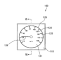
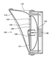
このような自動車用計器は、視認性や意匠性を向上させるために、種々の表示方法が提案されている(例えば、特許文献1など参照。)。特許文献1などに示された自動車用計器103は、図5および図6に示すように、見返し板110と、円板状に形成された文字板121と、前記文字板121の前面側で表示意匠を指示する指針126と、前記文字板121の前面に設けられ且つ当該文字板121の外周側に設けられたリング部材129と、文字板121の後面側に設けられた光源133と、前記指針126を駆動する内機138と、を備えており、前記光源133によって指針126を光輝させている。
For such an automobile instrument, various display methods have been proposed in order to improve visibility and designability (see, for example, Patent Document 1). As shown in FIG. 5 and FIG. 6, the
しかしながら、前述した特許文献1などに示された従来の自動車用計器は、リング部材129自体が光輝しないため、ありふれた意匠となっており、斬新な意匠ではないという問題があった。
However, the conventional automotive instrument disclosed in Patent Document 1 described above has a problem that the
本発明は、かかる問題を解決することを目的としている。即ち、本発明は、意匠性を向上させるとともに斬新な意匠表現とした自動車用計器を提供することを目的とする。 The present invention aims to solve this problem. That is, an object of the present invention is to provide an automotive instrument with improved design and a novel design expression.
前記課題を解決し目的を達成するために、請求項1に記載された発明は、表示意匠が設けられた文字板と、前記文字板の裏面側に設けられた光源と、前記文字板の前面側で前記表示意匠を指示する指針と、前記指針を駆動する内機と、前記文字板の前面に設けられ且つ当該文字板の外周側に設けられたリング部材と、前記リング部材の外周面の周囲に延在された見返し部材と、を有する自動車用計器において、前記自動車用計器は、前記文字板の裏面に設けられ且つ前記光源の光を当該文字板と前記リング部材とに導光する導光部材を備え、且つ、前記リング部材の前記外周面には、前記導光部材から導光された光を出射する出射部が設けられていることを特徴とする自動車用計器。 In order to solve the problems and achieve the object, the invention described in claim 1 includes a dial plate provided with a display design, a light source provided on a back side of the dial plate, and a front surface of the dial plate. A pointer that indicates the display design on the side, an internal unit that drives the pointer, a ring member that is provided on the front surface of the dial and provided on the outer peripheral side of the dial, and an outer peripheral surface of the ring member An automotive instrument having a turn-around member extending to the periphery, wherein the automotive instrument is provided on a back surface of the dial and guides light of the light source to the dial and the ring member. An automobile instrument comprising an optical member, and an emission portion for emitting light guided from the light guide member is provided on the outer peripheral surface of the ring member.
請求項2に記載の発明は、前記見返し部材には、前記リング部材の前記外周面に対向する対向部と、前記対向部から立設され且つ当該対向部の周囲に設けられた立設部と、が設けられていることを特徴とする請求項1に記載の自動車用計器である。 According to a second aspect of the present invention, the facing member includes a facing portion that faces the outer peripheral surface of the ring member, and a standing portion that is erected from the facing portion and provided around the facing portion. The vehicle instrument according to claim 1, further comprising:
請求項3に記載された発明は、前記リング部材の前記外周面には、前記見返し部材の裏面側に延出された延出部が設けられていることを特徴とする請求項1又は請求項2に記載の自動車用計器である。
The invention described in
請求項4に記載された発明は、前記リング部材の前記外周面と前記見返し部材の対向部との間には、間隙が設けられていることを特徴とする請求項1ないし請求項3のうちいずれか一項に記載の自動車用計器である。 The invention described in claim 4 is characterized in that a gap is provided between the outer peripheral surface of the ring member and the facing portion of the facing member. It is a meter for cars given in any 1 paragraph.
請求項5に記載された発明は、前記見返し部材は、前記対向部に模様意匠が設けられていることを特徴とする請求項1ないし請求項4のうちいずれか一項に記載の自動車方形器である。 The invention described in claim 5 is the automobile rectangular shape according to any one of claims 1 to 4, wherein the facing member is provided with a pattern design in the facing portion. It is.
請求項1に記載された発明によれば、自動車用計器は、リング部材に光源の光を導光すると共に当該リング部材の外周面に設けられた出射面から当該光を出射し、この出射した光によって前記リング部材の外周面の周囲に延在された見返し部材を照明するため、リング部材が光輝すると共に、見返し部材を照明した光が間接光となって運転者に視認される。このため、意匠性が大幅に向上するとともに、従来にはない斬新な意匠表現することができる。 According to the invention described in claim 1, the automotive instrument guides the light from the light source to the ring member and emits the light from the emission surface provided on the outer peripheral surface of the ring member. Since the turning member extending around the outer peripheral surface of the ring member is illuminated by light, the ring member shines, and the light that illuminates the turning member becomes indirect light and is visually recognized by the driver. For this reason, the designability is greatly improved, and a novel design expression that has not existed before can be expressed.
また、自動車用計器は、リング部材が光輝すると共に、見返し部材を照明した光が間接光となって運転者に視認されるため、リング部材とその周辺との輝度差の変化を抑えることができる。従って、運転者に視認される自動車用計器の印象の変化を抑えることができる。 In addition, since the ring member shines and the light that illuminates the turn-back member becomes indirect light and is visually recognized by the driver, the automobile instrument can suppress a change in the luminance difference between the ring member and its surroundings. . Therefore, it is possible to suppress a change in the impression of the automotive instrument that is visually recognized by the driver.
請求項2に記載された発明によれば、自動車用計器は、リング部材の外周面に設けられた出射面から出射した光によって見返し部材の立設部を照明するため、奥行きや厚みといった印象が強くなり、立体感を強調した表現ができる。 According to the invention described in claim 2, since the automotive instrument illuminates the standing portion of the turning member with the light emitted from the emitting surface provided on the outer peripheral surface of the ring member, there is an impression of depth and thickness. The expression becomes stronger and emphasizes the three-dimensional effect.
請求項3に記載された発明によれば、自動車用計器は、見返し部材の裏面側に延出した延出部をリング部材の外周面に設けたため、延出部自体が光輝する。このため、鮮明な印象を表現することができる。
According to the invention described in
請求項4に記載された発明によれば、自動車用計器は、延出部の光輝を間隙から視認できると共に、見返し部材からの光を間接光として視認できるため、延出部の明瞭な光と、見返し部材のぼんやりとした光との組み合わせによって、周囲と一体化した纏まり感を表現することができる。 According to the invention described in claim 4, the automotive instrument can visually recognize the brightness of the extending portion from the gap and can visually recognize the light from the turning member as indirect light. The feeling of unity integrated with the surroundings can be expressed by combination with the light of the turning member.
以下、本発明の実施形態について、図1〜図4を参照して説明する。
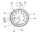
本発明の一実施形態にかかる自動車用計器としてのスピードメータ3は、図1に示すように、車速と燃料残量とを表示する表示意匠としての文字意匠22と目盛意匠23とが設けられた文字板21と、前記車速を表示する前記文字意匠22と前記目盛意匠23とを指示する指針26と、前記燃料残量を表示する前記文字意匠22と前記目盛意匠23とを指示する指針27と、前記文字板21の前面に設けられ且つ当該文字板21の外周側に設けられたリング部材29と、前記リング部材29の外周面30から延在された見返し板10と、を備えている。なお、本発明にかかる自動車用計器は、スピードメータ3に限定されるものではなく、エンジン回転数を表示するタコメータ4等の種々のメータであっても良い。
Hereinafter, embodiments of the present invention will be described with reference to FIGS.
As shown in FIG. 1, a
文字意匠22は、前記文字板21の外周側に設けられ且つ同心円上に設けられている。文字意匠22は、複数(図示例では、20km/h毎に、10個)設けられ且つ等間隔で設けられている。文字意匠22は、白色の透光性インクをスクリーン印刷して形成されている。
The
目盛意匠23は、前記文字板21の外周側に設けられ且つ前記文字意匠22よりも外側に設けられている。目盛意匠23は、同心円上に等間隔で複数(図示例では、10個)設けられている。目盛意匠23は、白色の透光性インクをスクリーン印刷して形成されている。
The
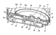
文字板21は、ポリカーボネート樹脂等の透明合成樹脂からなり、円盤状に形成されている。文字板21は、前述した文字意匠22と目盛意匠23といった表示意匠の他は、黒色の遮光性インクが印刷されて形成されている。文字板21は、図2および図3に示すように、文字意匠22と目盛意匠23とを光輝させる光源35と、前記光源35の光を前記文字意匠22と前記目盛意匠23とに導光する導光部材としての導光板41と、時速を表示する表示意匠としてのkm/h部を光輝させる光源36と、を備えている。
The
光源35,36は、白色光を照明する発光ダイオード(LED、Light Emitting Diode)からなる。光源35,36は、イグニッションオン時およびライトスイッチオン時に発生する所定のトリガ信号に応答して、点灯するように構成されている。
The
導光板41は、前記文字板21の裏面に設けられ且つ当該文字板21の外周側に設けられている。導光板41は、前記文字板21の外周側に設けられていると共に、前記リング部材29の全幅に亘って設けられている。導光板41は、環状に形成されていると共に、外周面から前記光源35に向かって延長され且つ当該光源35の光を受光する受光部41aが形成されている。導光板41は、アクリル樹脂やポリカーボネート樹脂等の透明性の高い合成樹脂からなり、光散乱効果を有する光拡散剤が分散されている。光拡散剤としては、酸化チタンや炭酸カルシウム等の無機微粒子、ポリスチレン樹脂やシリコーン樹脂等の有機架橋微粒子などが用いられている。
The
指針26は、軸部26aと、前記文字意匠22と目盛意匠23とを指示する針部26bと、を備え、前記軸部26aと前記針部26bとが一体に成形されている。指針26は、前記軸部26aに光を照明する光源33と、前記指針26を軸支すると共に当該指針26を回動させる内機38と、を備えている。指針26は、ポリカーボネート樹脂等の導光性の高い合成樹脂からなる。
The
軸部26aは、前面と周面とが黒色の遮光性塗料で塗装されている。針部26bは、底面が赤色の透光性膜が転写されている。このため、前記光源33の点灯によって針部26bが赤色に光輝する。
The
光源33は、白色光を照明する発光ダイオードからなる。光源33は、イグニッションオン時およびライトスイッチオン時に発生する所定のトリガ信号に応答して、点灯するように構成されている。
The
内機38は、前記指針26の前記軸部26aが嵌入された回動軸と、前記回動軸を回動させる減速ギヤと、前記減速ギヤを駆動するステッピングモータと、前記ステッピングモータを制御する電子回路と、を備えている。
The
指針27は、軸部と、文字意匠22(燃料残量が空のE部、燃料残量が半分の1/2部、および、燃料残量が満杯のF部)と目盛意匠23とを指示する針部と、を備えている。指針27は、前記軸部に白色光を照明する発光ダイオード等の光源34と、前記軸部を軸支すると共に前記指針27を回動させる内機39と、を備えている。なお、燃料残量を指示する指針27を備えないスピードメータ3であっても良い。
The
前記光源33〜36と前記内機38,39とは、前述したトリガ信号に応答して前記光源33〜36を点灯したり各種センサの信号に基づいて前記内機38,39を制御したりする制御装置を構成する電子部品37等と共に基板31に実装されている。基板31は、前記見返し板10の裏面に取り付けられた収容カバー52と当該収容カバー52を覆う背面カバー51との間に配されている。収容カバー52には、電子部品37や光源33〜36などが収容されている。背面カバー51には、内機38,39などが収容されている。
The
リング部材29は、図3および図4に示すように、円環状に形成されていると共に、外周面30側が内周面29d側よりも厚肉に形成された傾斜面29aが形成されている。リング部材29の外周面30には、環状に形成され且つ前記光源35から前記導光板41と前記文字板21とを介して導光された光を出射する出射部としての環状出射面29bと、前記見返し板10の裏面に延出されて環状に形成された延出部としての環状延出部29cと、が設けられている。リング部材29は、ポリカーボネート樹脂等の透光性の高い合成樹脂に前述した光拡散剤が分散されて面発光するように形成されている。リング部材29は、前記合成樹脂に紺色等の樹脂用顔料が添加されて着色されている。
As shown in FIGS. 3 and 4, the
見返し板10は、前記スピードメータ3の前面パネルを構成している。見返し板10は、ポリプロピレン樹脂などの合成樹脂からなり、暗色(好適には黒色)の合成樹脂用顔料によって着色され、遮光性を有している。見返し板10には、前記リング部材29の外周面30に対向して環状に形成された対向部11と、前記対向部11の周囲から立設され且つ当該対向部11を取り囲む立設部10bと、が設けられている。見返し板10は、前面に表ガラスが設けられており、スピードメータ3内に塵埃などが侵入することが防止される。
The facing
対向部11には、模様意匠としての模様凹部10aが周方向に多数設けられている。模様凹部10aは、前記周方向に対して直交する方向に設けられている。模様意匠は、市松模様、格子模様、および、縞模様などの繰り返し模様であっても良い。対向部11は、図4に示すように、当該対向部11と、前記リング部材29の環状出射面29bとの間に、間隙hが設けられている。このため、文字板21の外周部が変化に富んだ照明表現として運転者に視認される。
The opposing
立設部10bは、図2に示すように、スピードメータ3の中心を通る垂直線上において、当該スピードメータ3の上部側で突出量が最大に形成されていると共に、前記スピードメータ3の下部側で突出量が最小に形成されている。立設部10bは、図2に示すように、前記上部側から下部側に向かって徐々に突出量が減少する断面円弧状に形成されている。
As shown in FIG. 2, the
以下、前述の如く構成されたスピードメータ3の照明の動作について説明する。
Hereinafter, the illumination operation of the
スピードメータ3は、イグニッションオン時やライトスイッチオン時に発生する所定のトリガ信号に応答して、指針26の軸部26aを照明する光源33と、指針27の軸部を照明する光源34と、導光板41の受光部41aを照明する光源35と、文字板21上の表示意匠としてのkm/h部を照明する光源36と、が点灯する。なお、スピードメータ3は、常時点灯する自発光式であっても良い。
The
前記光源33に照明された指針26は、当該光源33の光が軸部26a内で屈折と散乱とをされて針部26bに伝搬され、前記針部26b内で散乱されて当該針部26bが均一に光輝する。針部26bは、赤色の透明膜が転写されているため、赤色に光輝する。
The
前記光源34に照明された指針27は、当該光源34の光が軸部内で屈折と散乱とをされて針部に伝搬され、前記針部内で散乱されて当該針部が均一に光輝する。針部は、赤色の透明膜が転写されているため、赤色に光輝する。
The
前記光源35に照明された導光板41は、当該光源35の光が受光部41a内で屈折と散乱とをされて前記導光板41に均一に伝搬され、文字板21の外周側と、リング部材29とに均一に出射される。
In the
前記導光板41から文字板21の外周側に均一に出射された光は、透光性インクで形成された表示意匠としての文字意匠22と目盛意匠23とを均一に白色に光輝させる。前記光源36に照明された文字板21は、透光性インクで形成された表示意匠としてのkm/h部を白色に光輝させる。このとき、文字板21上の前記表示意匠の他の部分は、黒色の遮光性インクが印刷されているため、光輝されない。
The light uniformly emitted from the
前記導光板41からリング部材29に均一に出射された光は、前記リング部材29内で散乱されて当該リング部材29を均一に光輝させ、前記リング部材29の外周面30に設けられた環状延出部29cを均一に光輝させ、前記外周面30に設けられた環状出射面29bから光が均一に出射される。このとき、リング部材29は紺色の合成樹脂用顔料で着色されているため、紺色に光輝する。
The light uniformly emitted from the
前記環状出射面29bから出射された光は、当該環状出射面29bに対向する見返し板10の対向部11を照明する。このとき、均一に光輝したリング部材29によって、文字板21の外周側から内周側に向かって次第に薄暗くなる光のグラデーションが形成される。
The light emitted from the annular exit surface 29b illuminates the facing
前記環状出射面29bから出射した光で照明された対向部11は、当該対向部11に設けられた模様意匠としての模様凹部10aが照明される。このとき、照明された模様凹部10aから立設部10bにかけては、次第に薄暗くなる光のグラデーションが形成される。また、模様凹部10aの模様が光の濃淡として浮かび上がって、深みのある立体感が表現される。また、前記環状延出部29cの光輝と、模様凹部10aから立設部10bにかけて形成された光のグラデーションとによって、文字板21の外周部の立体感が際だつと共に変化に富んだ斬新な表現となる。
The facing
上述のように、本発明のスピードメータ3は、リング部材29が光輝すると共に、見返し板10を前記リング部材29の外周面30の環状出射面29bが照明するため、リング部材とその周辺との輝度差の変化を抑えることができる。従って、周囲の環境の明るさの変化によって運転者に視認される印象が変化することを防止できる。さらには、光のグラデーションと、模様凹部10aの浮かび上がりと、各部材自体の光輝と、出射された光による照明とによって、文字板21の外周部が、変化に富んだ照明表現として運転者等に視認され、斬新な印象を与えることができる。
As described above, in the
なお、リング部材29の傾斜面29aと内周面29dとを遮光性塗料等で塗装し、文字板21がより一層落ち着いた印象となる照明表現としても良い。また、リング部材29と異なる色の透光性塗料で着色し、光の色相や彩度を変化させるようにし、見返し板10の色調を変化させて運転者等に視認させても良い。
Note that the
本実施形態によれば、スピードメータ3は、表示意匠としての文字意匠22と目盛意匠23とが設けられた文字板21と、前記文字板21の裏面側に設けられた光源33〜36と、前記文字板21の前面側で前記文字意匠22と目盛意匠23とを指示する指針26,27と、前記指針26,27を駆動する内機38,39と、前記文字板21の前面に設けられ且つ当該文字板21の外周側に設けられたリング部材29と、前記リング部材29の外周面30の周囲に延在された見返し板10と、を有しており、前記文字板21の裏面に設けられ且つ前記光源35の光を当該文字板21と前記リング部材29とに導光する導光板41を備え、且つ、前記リング部材29の前記外周面30には、前記導光板41から導光された光を出射する環状出射面29bが設けられている。
According to this embodiment, the
このため、スピードメータ3は、リング部材29に光源35の光を導光すると共に当該リング部材29の外周面30に設けられた環状出射面29bから当該光を出射し、この出射した光によって前記リング部材29の前記外周面30に延在された見返し板10を照明するため、リング部材29が光輝すると共に、見返し板10を照明した光が間接光となって運転者に視認される。このため、意匠性を向上させるとともに斬新な意匠表現とすることができる。
For this reason, the
また、リング部材29が光輝すると共に、見返し板10を照明した光が間接光となって運転者に視認されるため、リング部材29とその周辺との輝度差の変化を抑えることができる。従って、運転者に視認されるスピードメータ3の印象の変化を抑えることができる。
In addition, the
また、前記見返し板10には、前記リング部材29の前記外周面30に対向する対向部11から立設された立設部10bが設けられているため、前記リング部材29の環状出射面29bから出射した光によって見返し板10の立設部10bを照明する。このため、スピードメータ3は、奥行きや厚みといった印象を強く運転者等に付与し、立体感を強調した照明表現となる。
Further, since the facing
また、前記リング部材29の前記外周面30には、前記見返し板10の裏面側に延出された環状延出部29cが設けられているため、環状延出部29c自体が光輝し、スピードメータ3にシャープな印象を与えることができる。
Further, since the outer peripheral surface 30 of the
また、前記リング部材29の前記外周面30と前記見返し板10との間には、間隙hが設けられているため、環状延出部29cの光輝を間隙hから視認できると共に、見返し板10からの光を間接光として視認できる。このため、環状延出部29cの明瞭な光と、見返し板10に照明されたぼんやりとした光との組み合わせによって、スピードメータ3の文字板21の外周側が周囲と一体化した纏まり感を演出することができる。
Further, since a gap h is provided between the outer peripheral surface 30 of the
また、前記見返し板10は、前記対向部11に模様意匠としての模様凹部10aが設けられているため、見返し板10の対向部11に設けられた模様凹部10aに、リング部材29の外周面30から光を照明することができる。このため、前記模様凹部10aを浮かび上がらせることができる。このため、人目を引きつける表現ができる。
Further, since the facing
なお、前述した実施形態は本発明の代表的な形態を示したに過ぎず、本発明は、実施形態に限定されるものではない。即ち、本発明の骨子を逸脱しない範囲で種々変形して実施することができる。 In addition, embodiment mentioned above only showed the typical form of this invention, and this invention is not limited to embodiment. That is, various modifications can be made without departing from the scope of the present invention.
3 スピードメータ(自動車用計器)
10 見返し板(見返し部材)
10a 模様凹部(模様意匠)
10b 立設部
11 対向部
21 文字板
22 数字意匠(表示意匠)
23 目盛意匠(表示意匠)
26,27 指針
29 リング部材
29b 環状出射面(出射部)
29c 環状延出部(延出部)
30 外周面
33,34,35,36 光源
38,39 内機
41 導光板(導光部材)
41a 受光部
h 間隙
3 Speedometer (automobile instrument)
10 Turn-around plate (turn-back member)
10a Pattern recess (pattern design)
23 Scale design (display design)
26, 27
29c Annular extension part (extension part)
30 Outer
41a Light-receiving part h Gap
Claims (4)
前記自動車用計器は、前記文字板の裏面に設けられ且つ前記光源の光を当該文字板と前記リング部材とに導光する導光部材を備え、且つ、
前記リング部材の前記外周面には、前記導光部材から導光された光を出射する出射部が設けられていることを特徴とする自動車用計器。 A dial provided with a display design, a light source provided on the back side of the dial, a pointer indicating the display design on the front side of the dial, an internal unit for driving the pointer, and the character In an automotive instrument having a ring member provided on the front surface of the plate and provided on the outer peripheral side of the dial plate, and a turning member extending around the outer peripheral surface of the ring member,
The automobile instrument includes a light guide member that is provided on a back surface of the dial and guides light of the light source to the dial and the ring member, and
The automotive instrument according to claim 1, wherein an emission portion that emits light guided from the light guide member is provided on the outer peripheral surface of the ring member.
Priority Applications (1)
| Application Number | Priority Date | Filing Date | Title |
|---|---|---|---|
| JP2011120597A JP5725976B2 (en) | 2011-05-30 | 2011-05-30 | Automotive instrument |
Applications Claiming Priority (1)
| Application Number | Priority Date | Filing Date | Title |
|---|---|---|---|
| JP2011120597A JP5725976B2 (en) | 2011-05-30 | 2011-05-30 | Automotive instrument |
Publications (2)
| Publication Number | Publication Date |
|---|---|
| JP2012247357A true JP2012247357A (en) | 2012-12-13 |
| JP5725976B2 JP5725976B2 (en) | 2015-05-27 |
Family
ID=47467910
Family Applications (1)
| Application Number | Title | Priority Date | Filing Date |
|---|---|---|---|
| JP2011120597A Active JP5725976B2 (en) | 2011-05-30 | 2011-05-30 | Automotive instrument |
Country Status (1)
| Country | Link |
|---|---|
| JP (1) | JP5725976B2 (en) |
Cited By (2)
| Publication number | Priority date | Publication date | Assignee | Title |
|---|---|---|---|---|
| JP2015137981A (en) * | 2014-01-23 | 2015-07-30 | カルソニックカンセイ株式会社 | Scale ring illuminating device |
| JP2019039814A (en) * | 2017-08-25 | 2019-03-14 | 矢崎総業株式会社 | Vehicle display device |
Citations (6)
| Publication number | Priority date | Publication date | Assignee | Title |
|---|---|---|---|---|
| JP2003139582A (en) * | 2001-10-31 | 2003-05-14 | Nippon Seiki Co Ltd | Measuring instrument |
| JP2007271271A (en) * | 2006-03-30 | 2007-10-18 | Calsonic Kansei Corp | Measuring instrument device for vehicle |
| JP2007271328A (en) * | 2006-03-30 | 2007-10-18 | Nippon Seiki Co Ltd | Metering device |
| JP2008261664A (en) * | 2007-04-10 | 2008-10-30 | Calsonic Kansei Corp | Meter device |
| JP2010151489A (en) * | 2008-12-24 | 2010-07-08 | Nippon Seiki Co Ltd | Meter for vehicle |
| JP2010151789A (en) * | 2008-07-15 | 2010-07-08 | Nippon Seiki Co Ltd | Measuring instrument |
-
2011
- 2011-05-30 JP JP2011120597A patent/JP5725976B2/en active Active
Patent Citations (6)
| Publication number | Priority date | Publication date | Assignee | Title |
|---|---|---|---|---|
| JP2003139582A (en) * | 2001-10-31 | 2003-05-14 | Nippon Seiki Co Ltd | Measuring instrument |
| JP2007271271A (en) * | 2006-03-30 | 2007-10-18 | Calsonic Kansei Corp | Measuring instrument device for vehicle |
| JP2007271328A (en) * | 2006-03-30 | 2007-10-18 | Nippon Seiki Co Ltd | Metering device |
| JP2008261664A (en) * | 2007-04-10 | 2008-10-30 | Calsonic Kansei Corp | Meter device |
| JP2010151789A (en) * | 2008-07-15 | 2010-07-08 | Nippon Seiki Co Ltd | Measuring instrument |
| JP2010151489A (en) * | 2008-12-24 | 2010-07-08 | Nippon Seiki Co Ltd | Meter for vehicle |
Cited By (2)
| Publication number | Priority date | Publication date | Assignee | Title |
|---|---|---|---|---|
| JP2015137981A (en) * | 2014-01-23 | 2015-07-30 | カルソニックカンセイ株式会社 | Scale ring illuminating device |
| JP2019039814A (en) * | 2017-08-25 | 2019-03-14 | 矢崎総業株式会社 | Vehicle display device |
Also Published As
| Publication number | Publication date |
|---|---|
| JP5725976B2 (en) | 2015-05-27 |
Similar Documents
| Publication | Publication Date | Title |
|---|---|---|
| JP6063308B2 (en) | Three-dimensional design part structure of an automobile meter | |
| JP6478009B2 (en) | Display device | |
| JP2006201038A (en) | Display device | |
| JP4882092B2 (en) | Indicating instrument | |
| JP4792831B2 (en) | Instrument display board and pointer instrument having the same | |
| JP2006003341A (en) | Display | |
| JP5182216B2 (en) | Vehicle display device | |
| US20160161303A1 (en) | Structure of scale graduation and vehicle instrument | |
| JP2006194636A (en) | Pointer measuring meter | |
| JP2010223826A (en) | Mobile meter | |
| JP4977403B2 (en) | Vehicle display device | |
| JP4462138B2 (en) | Instrument display board and pointer instrument having the same | |
| JP5725976B2 (en) | Automotive instrument | |
| JP5045403B2 (en) | Pointer instrument | |
| JP4175308B2 (en) | Vehicle indicator instrument | |
| JP4603467B2 (en) | Instrument display board and pointer instrument having the same | |
| JP2007132818A (en) | Vehicle pointing instrument | |
| JP4858228B2 (en) | Pointer instrument | |
| JP4667896B2 (en) | Pointer instrument | |
| JP4933069B2 (en) | Vehicle indicator instrument | |
| JP4075843B2 (en) | Vehicle indicator instrument | |
| JP4229032B2 (en) | Vehicle indicator instrument | |
| JP4820224B2 (en) | Vehicle instrument | |
| JP4224751B2 (en) | Display device | |
| JP2006131209A (en) | Vehicular display device, and vehicular instrument equipped therewith |
Legal Events
| Date | Code | Title | Description |
|---|---|---|---|
| A621 | Written request for application examination |
Free format text: JAPANESE INTERMEDIATE CODE: A621 Effective date: 20140417 |
|
| A977 | Report on retrieval |
Free format text: JAPANESE INTERMEDIATE CODE: A971007 Effective date: 20150129 |
|
| A131 | Notification of reasons for refusal |
Free format text: JAPANESE INTERMEDIATE CODE: A131 Effective date: 20150203 |
|
| A521 | Request for written amendment filed |
Free format text: JAPANESE INTERMEDIATE CODE: A523 Effective date: 20150302 |
|
| TRDD | Decision of grant or rejection written | ||
| A01 | Written decision to grant a patent or to grant a registration (utility model) |
Free format text: JAPANESE INTERMEDIATE CODE: A01 Effective date: 20150324 |
|
| A61 | First payment of annual fees (during grant procedure) |
Free format text: JAPANESE INTERMEDIATE CODE: A61 Effective date: 20150331 |
|
| R150 | Certificate of patent or registration of utility model |
Ref document number: 5725976 Country of ref document: JP Free format text: JAPANESE INTERMEDIATE CODE: R150 |
|
| R250 | Receipt of annual fees |
Free format text: JAPANESE INTERMEDIATE CODE: R250 |
|
| R250 | Receipt of annual fees |
Free format text: JAPANESE INTERMEDIATE CODE: R250 |
|
| R250 | Receipt of annual fees |
Free format text: JAPANESE INTERMEDIATE CODE: R250 |
|
| R250 | Receipt of annual fees |
Free format text: JAPANESE INTERMEDIATE CODE: R250 |
|
| R250 | Receipt of annual fees |
Free format text: JAPANESE INTERMEDIATE CODE: R250 |
|
| R250 | Receipt of annual fees |
Free format text: JAPANESE INTERMEDIATE CODE: R250 |