JP2012244353A - Image processing device and method - Google Patents
Image processing device and method Download PDFInfo
- Publication number
- JP2012244353A JP2012244353A JP2011111576A JP2011111576A JP2012244353A JP 2012244353 A JP2012244353 A JP 2012244353A JP 2011111576 A JP2011111576 A JP 2011111576A JP 2011111576 A JP2011111576 A JP 2011111576A JP 2012244353 A JP2012244353 A JP 2012244353A
- Authority
- JP
- Japan
- Prior art keywords
- unit
- mode
- image
- prediction
- weight
- Prior art date
- Legal status (The legal status is an assumption and is not a legal conclusion. Google has not performed a legal analysis and makes no representation as to the accuracy of the status listed.)
- Abandoned
Links
Images


Classifications
-
- H—ELECTRICITY
- H04—ELECTRIC COMMUNICATION TECHNIQUE
- H04N—PICTORIAL COMMUNICATION, e.g. TELEVISION
- H04N19/00—Methods or arrangements for coding, decoding, compressing or decompressing digital video signals
- H04N19/10—Methods or arrangements for coding, decoding, compressing or decompressing digital video signals using adaptive coding
- H04N19/102—Methods or arrangements for coding, decoding, compressing or decompressing digital video signals using adaptive coding characterised by the element, parameter or selection affected or controlled by the adaptive coding
- H04N19/103—Selection of coding mode or of prediction mode
- H04N19/105—Selection of the reference unit for prediction within a chosen coding or prediction mode, e.g. adaptive choice of position and number of pixels used for prediction
-
- H—ELECTRICITY
- H04—ELECTRIC COMMUNICATION TECHNIQUE
- H04N—PICTORIAL COMMUNICATION, e.g. TELEVISION
- H04N19/00—Methods or arrangements for coding, decoding, compressing or decompressing digital video signals
- H04N19/10—Methods or arrangements for coding, decoding, compressing or decompressing digital video signals using adaptive coding
- H04N19/102—Methods or arrangements for coding, decoding, compressing or decompressing digital video signals using adaptive coding characterised by the element, parameter or selection affected or controlled by the adaptive coding
- H04N19/103—Selection of coding mode or of prediction mode
- H04N19/109—Selection of coding mode or of prediction mode among a plurality of temporal predictive coding modes
-
- H—ELECTRICITY
- H04—ELECTRIC COMMUNICATION TECHNIQUE
- H04N—PICTORIAL COMMUNICATION, e.g. TELEVISION
- H04N19/00—Methods or arrangements for coding, decoding, compressing or decompressing digital video signals
- H04N19/10—Methods or arrangements for coding, decoding, compressing or decompressing digital video signals using adaptive coding
- H04N19/134—Methods or arrangements for coding, decoding, compressing or decompressing digital video signals using adaptive coding characterised by the element, parameter or criterion affecting or controlling the adaptive coding
- H04N19/136—Incoming video signal characteristics or properties
- H04N19/137—Motion inside a coding unit, e.g. average field, frame or block difference
-
- H—ELECTRICITY
- H04—ELECTRIC COMMUNICATION TECHNIQUE
- H04N—PICTORIAL COMMUNICATION, e.g. TELEVISION
- H04N19/00—Methods or arrangements for coding, decoding, compressing or decompressing digital video signals
- H04N19/10—Methods or arrangements for coding, decoding, compressing or decompressing digital video signals using adaptive coding
- H04N19/169—Methods or arrangements for coding, decoding, compressing or decompressing digital video signals using adaptive coding characterised by the coding unit, i.e. the structural portion or semantic portion of the video signal being the object or the subject of the adaptive coding
- H04N19/17—Methods or arrangements for coding, decoding, compressing or decompressing digital video signals using adaptive coding characterised by the coding unit, i.e. the structural portion or semantic portion of the video signal being the object or the subject of the adaptive coding the unit being an image region, e.g. an object
- H04N19/174—Methods or arrangements for coding, decoding, compressing or decompressing digital video signals using adaptive coding characterised by the coding unit, i.e. the structural portion or semantic portion of the video signal being the object or the subject of the adaptive coding the unit being an image region, e.g. an object the region being a slice, e.g. a line of blocks or a group of blocks
-
- H—ELECTRICITY
- H04—ELECTRIC COMMUNICATION TECHNIQUE
- H04N—PICTORIAL COMMUNICATION, e.g. TELEVISION
- H04N19/00—Methods or arrangements for coding, decoding, compressing or decompressing digital video signals
- H04N19/10—Methods or arrangements for coding, decoding, compressing or decompressing digital video signals using adaptive coding
- H04N19/169—Methods or arrangements for coding, decoding, compressing or decompressing digital video signals using adaptive coding characterised by the coding unit, i.e. the structural portion or semantic portion of the video signal being the object or the subject of the adaptive coding
- H04N19/17—Methods or arrangements for coding, decoding, compressing or decompressing digital video signals using adaptive coding characterised by the coding unit, i.e. the structural portion or semantic portion of the video signal being the object or the subject of the adaptive coding the unit being an image region, e.g. an object
- H04N19/176—Methods or arrangements for coding, decoding, compressing or decompressing digital video signals using adaptive coding characterised by the coding unit, i.e. the structural portion or semantic portion of the video signal being the object or the subject of the adaptive coding the unit being an image region, e.g. an object the region being a block, e.g. a macroblock
-
- H—ELECTRICITY
- H04—ELECTRIC COMMUNICATION TECHNIQUE
- H04N—PICTORIAL COMMUNICATION, e.g. TELEVISION
- H04N19/00—Methods or arrangements for coding, decoding, compressing or decompressing digital video signals
- H04N19/50—Methods or arrangements for coding, decoding, compressing or decompressing digital video signals using predictive coding
- H04N19/503—Methods or arrangements for coding, decoding, compressing or decompressing digital video signals using predictive coding involving temporal prediction
- H04N19/51—Motion estimation or motion compensation
- H04N19/577—Motion compensation with bidirectional frame interpolation, i.e. using B-pictures
Landscapes
- Engineering & Computer Science (AREA)
- Multimedia (AREA)
- Signal Processing (AREA)
- Compression Or Coding Systems Of Tv Signals (AREA)
Abstract
Description
本開示は、画像処理装置および方法に関し、特に、符号化効率を向上させることができるようにした画像処理装置および方法に関する。 The present disclosure relates to an image processing apparatus and method, and more particularly, to an image processing apparatus and method capable of improving encoding efficiency.
近年、画像情報をデジタルとして取り扱い、その際、効率の高い情報の伝送、蓄積を目的とし、画像情報特有の冗長性を利用して、離散コサイン変換等の直交変換と動き補償により圧縮するMPEG(Moving Picture Experts Group)などの方式に準拠した装置が、放送局などの情報配信、及び一般家庭における情報受信の双方において普及しつつある。 In recent years, image information is handled as digital data, and MPEG (compressed by orthogonal transform such as discrete cosine transform and motion compensation is used for the purpose of efficient transmission and storage of information. A device conforming to a system such as Moving Picture Experts Group) is becoming popular in both information distribution at broadcasting stations and information reception in general households.
特に、MPEG2(ISO(International Organization for Standardization)/IEC(International Electrotechnical Commission) 13818-2)は、汎用画像符号化方式として定義されており、飛び越し走査画像及び順次走査画像の双方、並びに標準解像度画像及び高精細画像を網羅する標準で、プロフェッショナル用途及びコンシューマ用途の広範なアプリケーションに現在広く用いられている。MPEG2圧縮方式を用いることにより、例えば720×480画素を持つ標準解像度の飛び越し走査画像であれば4〜8Mbps、1920×1088画素を持つ高解像度の飛び越し走査画像であれば18〜22Mbpsの符号量(ビットレート)を割り当てることで、高い圧縮率と良好な画質の実現が可能である。 In particular, MPEG2 (ISO (International Organization for Standardization) / IEC (International Electrotechnical Commission) 13818-2) is defined as a general-purpose image coding system, which includes both interlaced scanning images and progressive scanning images, as well as standard resolution images and This standard covers high-definition images and is currently widely used in a wide range of professional and consumer applications. By using the MPEG2 compression method, for example, a standard resolution interlaced scanning image having 720 × 480 pixels is 4 to 8 Mbps, and a high resolution interlaced scanning image having 1920 × 1088 pixels is 18 to 22 Mbps. (Bit rate) can be assigned to achieve a high compression rate and good image quality.
MPEG2は主として放送用に適合する高画質符号化を対象としていたが、MPEG1より低い符号量(ビットレート)、つまりより高い圧縮率の符号化方式には対応していなかった。携帯端末の普及により、今後そのような符号化方式のニーズは高まると思われ、これに対応してMPEG4符号化方式の標準化が行われた。画像符号化方式に関しては、1998年12月にISO/IEC 14496-2としてその規格が国際標準に承認された。 MPEG2 was mainly intended for high-quality encoding suitable for broadcasting, but did not support encoding methods with a lower code amount (bit rate) than MPEG1, that is, a higher compression rate. With the widespread use of mobile terminals, the need for such an encoding system is expected to increase in the future, and the MPEG4 encoding system has been standardized accordingly. Regarding the image coding system, the standard was approved as an international standard as ISO / IEC 14496-2 in December 1998.
更に、近年、当初テレビ会議用の画像符号化を目的として、H.26L (ITU-T(International Telecommunication Union Telecommunication Standardization Sector) Q6/16 VCEG(Video Coding Expert Group))という標準の規格化が進んでいる。H.26LはMPEG2やMPEG4といった従来の符号化方式に比べ、その符号化、復号化により多くの演算量が要求されるものの、より高い符号化効率が実現されることが知られている。また、現在、MPEG4の活動の一環として、このH.26Lをベースに、H.26Lではサポートされない機能をも取り入れ、より高い符号化効率を実現する標準化がJoint Model of Enhanced-Compression Video Codingとして行われている。 Furthermore, in recent years, the standardization of the standard called H.26L (ITU-T (International Telecommunication Union Telecommunication Standardization Sector) Q6 / 16 VCEG (Video Coding Expert Group)) has progressed for the purpose of image coding for the initial video conference. Yes. H.26L is known to achieve higher encoding efficiency than the conventional encoding schemes such as MPEG2 and MPEG4, although a large amount of calculation is required for encoding and decoding. Currently, as part of MPEG4 activities, standardization to achieve higher coding efficiency based on this H.26L and incorporating functions not supported by H.26L is performed as Joint Model of Enhanced-Compression Video Coding. It has been broken.
標準化のスケジュールとしては、2003年3月にはH.264及びMPEG-4 Part10 (Advanced Video Coding、以下AVCと記す)という名の元に国際標準となった。 The standardization schedule became an international standard in March 2003 under the names of H.264 and MPEG-4 Part 10 (Advanced Video Coding, hereinafter referred to as AVC).
更に、その拡張として、RGBや4:2:2、4:4:4といった、業務用に必要な符号化ツールや、MPEG-2で規定されていた8x8DCT(Discrete Cosine Transform)や量子化マトリクスをも含んだFRExt(Fidelity Range Extension)の標準化が2005年2月に完了し、これにより、AVCを用いて、映画に含まれるフィルムノイズをも良好に表現することが可能な符号化方式となって、Blu-Ray Disc等の幅広いアプリケーションに用いられる運びとなった。 Furthermore, as an extension, RGB, 4: 2: 2, 4: 4: 4 encoding tools necessary for business use, 8x8DCT (Discrete Cosine Transform) and quantization matrix specified by MPEG-2 are added. FRExt (Fidelity Range Extension) standardization was completed in February 2005, and as a result, it became an encoding method that can well express film noise contained in movies using AVC. It has been used for a wide range of applications such as Blu-Ray Disc.
しかしながら、昨今、ハイビジョン画像の4倍の、4000×2000画素程度の画像を圧縮したい、或いは、インターネットのような、限られた伝送容量の環境において、ハイビジョン画像を配信したいといった、更なる高圧縮率符号化に対するニーズが高まっている。このため、ITU-T傘下のVCEG(Video Coding Expert Group)において、符号化効率の改善に関する検討が継続され行なわれている。 However, in recent years, even higher compression ratios such as wanting to compress images of about 4000 x 2000 pixels, which is four times higher than high-definition images, or distributing high-definition images in a limited transmission capacity environment such as the Internet. There is a growing need for encoding. For this reason, in the VCEG (Video Coding Expert Group) under the ITU-T, studies on improving the coding efficiency are being continued.
ところで、従来のように、マクロブロックサイズを16画素×16画素とするのは、次世代符号化方式の対象となるような、UHD(Ultra High Definition;4000画素×2000画素)といった大きな画枠に対しては、最適ではない恐れがあった。 By the way, the conventional macroblock size of 16 pixels × 16 pixels is a large image frame such as UHD (Ultra High Definition: 4000 pixels × 2000 pixels), which is the target of the next-generation encoding method. There was a fear that it was not optimal.
そこで、現在、AVCより更なる符号化効率の向上を目的として、ITU-Tと、ISO/IECの共同の標準化団体であるJCTVC(Joint Collaboration Team - Video Coding)により、HEVC(High Efficiency Video Coding)と呼ばれる符号化方式の標準化が進められている(例えば、非特許文献1参照)。 Therefore, for the purpose of further improving the encoding efficiency compared to AVC, HEVC (High Efficiency Video Coding) is being developed by JCTVC (Joint Collaboration Team-Video Coding), a joint standardization organization of ITU-T and ISO / IEC. Is being standardized (for example, see Non-Patent Document 1).
このHEVC符号化方式においては、AVCにおけるマクロブロックと同様の処理単位としてコーディングユニット(CU(Coding Unit))が定義されている。このCUは、AVCのマクロブロックのようにサイズが16×16画素に固定されず、それぞれのシーケンスにおいて、画像圧縮情報中において指定される。 In this HEVC encoding system, a coding unit (CU (Coding Unit)) is defined as a processing unit similar to a macroblock in AVC. The CU is not fixed to a size of 16 × 16 pixels like the AVC macroblock, and is specified in the image compression information in each sequence.
ところで、MPEG2やMPEG4においては、例えば、フェードシーンのように、動きが存在するが、明るさが変化するようなシーケンスにおいては、明るさの変化を吸収する符号化ツールが用意されていないため、符号化効率が低下するという問題を有していた。 By the way, in MPEG2 and MPEG4, for example, in a sequence where there is motion, such as a fade scene, but the brightness changes, there is no encoding tool to absorb the change in brightness. There was a problem that the encoding efficiency was lowered.
かかる問題を解決するため、AVCにおいては、重み付き予測処理が設けられていた(例えば非特許文献2参照)。AVCにおいては、スライス単位で、この重み付け予測を用いる・用いないを指定することが可能である。 In order to solve such a problem, weighted prediction processing is provided in AVC (for example, see Non-Patent Document 2). In AVC, it is possible to specify whether or not to use this weighted prediction for each slice.
ところで、画面の一部は輝度変化があるが、一部は変化がないままであるということがあり得る。しかしながら、AVCにおける重み付け予測では、これに対応することが出来ないため、重み付け予測による効率が低下する。例えば、レターボックス等のような、画面の端部が黒塗りの画像のような輝度変化の無い画像とされる場合、画面中央では輝度変化があったとしても、ピクチャ全体に重み付け予測を適用することは、輝度変化の無い画面端部においては適切ではなく、符号化効率の低下に繋がる恐れがあった。また、輝度変化が画面全体で一様に変化しない場合も、重み付け予測の予測精度が部分的に低減し、符号化効率の低下に繋がる恐れがあった。 By the way, it is possible that a part of the screen has a luminance change, but a part remains unchanged. However, since weighted prediction in AVC cannot cope with this, the efficiency by weighted prediction decreases. For example, when the edge of the screen is an image having no luminance change such as a black-painted image such as a letterbox, weight prediction is applied to the entire picture even if there is a luminance change at the center of the screen. This is not appropriate at the edge of the screen where there is no change in luminance, which may lead to a decrease in encoding efficiency. Further, even when the luminance change does not change uniformly over the entire screen, the prediction accuracy of the weighted prediction is partially reduced, which may lead to a decrease in encoding efficiency.
本開示は、このような状況に鑑みてなされたものであり、重み付け予測の制御単位をより小さな領域とすることにより、重み付け予測の予測精度の低減を抑制し、符号化効率の低減を抑制することができるようにすることを目的とする。 The present disclosure has been made in view of such a situation, and by reducing the control unit of the weighted prediction to a smaller area, the prediction accuracy of the weighted prediction is suppressed and the encoding efficiency is suppressed. The purpose is to be able to.
本開示の一側面は、画像を符号化のインター動き予測補償処理を重み係数で重み付けしながら行う重み付け予測のモードである重みモードを、所定の領域毎に判定する重みモード判定部と、前記重みモード判定部により判定された重みモードを示す重みモード情報を、前記領域毎に生成する重みモード情報生成部と、前記重みモード情報生成部により生成された前記重みモード情報を符号化する符号化部とを備える画像処理装置である。 One aspect of the present disclosure includes a weight mode determination unit that determines, for each predetermined region, a weight mode that is a weighted prediction mode in which an inter motion prediction compensation process for encoding an image is weighted with a weight coefficient, and the weight Weight mode information generation unit that generates weight mode information indicating the weight mode determined by the mode determination unit for each region, and encoding unit that encodes the weight mode information generated by the weight mode information generation unit An image processing apparatus.
前記重みモードは、前記重み係数を用いて前記インター動き予測補償処理を行う重み付け有りのモードと、前記重み係数を用いずに前記インター動き予測補償処理を行う重み付け無しのモードとを含むことができる。 The weighting mode may include a weighted mode in which the inter motion prediction compensation process is performed using the weighting factor and a non-weighted mode in which the inter motion prediction compensation processing is performed without using the weighting factor. .
前記重みモードは、前記重み係数を用いて、重み係数を伝送するExplicitモードで前記インター動き予測補償処理を行うモードと、前記重み係数を用いて、重み係数を伝送しないInplicitモードで前記インター動き予測補償処理を行うモードとを含むことができる。 The weight mode uses the weight coefficient to perform the inter motion prediction compensation process in an explicit mode that transmits a weight coefficient, and uses the weight coefficient to perform the inter motion prediction in an Inplicit mode that does not transmit a weight coefficient. And a mode for performing compensation processing.
前記重みモードは、互いに異なる重み係数を用いて前記インター動き予測補償処理を行う、複数の重み付け有りのモードを含むことができる。 The weighting mode may include a plurality of weighted modes in which the inter motion prediction compensation process is performed using different weighting factors.
前記重みモード情報生成部は、前記重みモード情報の代わりに、前記重みモードと、前記インター動き予測補償処理のモードを示すインター予測モードとの組み合わせを示すモード情報を生成することができる。 The weight mode information generation unit can generate mode information indicating a combination of the weight mode and an inter prediction mode indicating a mode of the inter motion prediction compensation process, instead of the weight mode information.
前記重みモード情報生成部が前記重みモード情報を生成する前記領域のサイズを制限する制限部をさらに備えることができる。 The weight mode information generation unit may further include a restriction unit that restricts a size of the region in which the weight mode information is generated.
前記領域は、前記インター動き予測補償処理の処理単位の領域であることができる。 The area may be an area of a unit of the inter motion prediction compensation process.
前記領域は、Largest Coding Unit、Coding Unit、若しくは、Prediction Unitであることができる。 The region may be a large coding unit, a coding unit, or a prediction unit.
前記符号化部は、前記重みモード情報をCABACで符号化することができる。 The encoding unit may encode the weight mode information using CABAC.
本開示の一側面は、また、画像処理装置の画像処理方法であって、重みモード判定部が、画像を符号化のインター動き予測補償処理を重み係数で重み付けしながら行う重み付け予測のモードである重みモードを、所定の領域毎に判定し、重みモード情報生成部が、判定された重みモードを示す重みモード情報を、前記領域毎に生成し、符号化部が、生成された前記重みモード情報を符号化する画像処理方法である。 One aspect of the present disclosure is also an image processing method of the image processing apparatus, in which the weight mode determination unit performs weighted prediction mode in which an inter motion prediction compensation process for encoding an image is performed while weighting with a weighting coefficient. A weight mode is determined for each predetermined area, a weight mode information generation unit generates weight mode information indicating the determined weight mode for each area, and an encoding unit generates the generated weight mode information. Is an image processing method for encoding.
本開示の他の側面は、画像の符号化において、インター動き予測補償処理を重み係数で重み付けしながら行う重み付け予測のモードである重みモードが、所定の領域毎に判定され、前記重みモードを示す重みモード情報が前記領域毎に生成され、前記画像とともに符号化されたビットストリームを復号し、前記ビットストリームに含まれる、前記重みモード情報を抽出する復号部と、前記復号部により復号されて抽出された前記重みモード情報に示される重みモードで、動き補償処理を行い、予測画像を生成する動き補償部とを備える画像処理装置である。 According to another aspect of the present disclosure, a weighting mode, which is a weighted prediction mode in which inter motion prediction compensation processing is weighted with a weighting coefficient in image coding, is determined for each predetermined region, and indicates the weighting mode. Weight mode information is generated for each region, a bit stream encoded with the image is decoded, and a decoding unit that extracts the weight mode information included in the bit stream, and is decoded and extracted by the decoding unit The image processing apparatus includes a motion compensation unit that performs motion compensation processing and generates a predicted image in the weight mode indicated in the weight mode information.
前記重みモードは、前記重み係数を用いて前記動き補償処理を行う重み付け有りのモードと、前記重み係数を用いずに前記動き補償処理を行う重み付け無しのモードとを含むことができる。 The weighting mode can include a weighted mode in which the motion compensation process is performed using the weighting factor, and an unweighted mode in which the motion compensation processing is performed without using the weighting factor.
前記重みモードは、前記重み係数を用いて、重み係数が伝送されるExplicitモードで前記動き補償処理を行うモードと、前記重み係数を用いて、重み係数が伝送されないInplicitモードで前記動き補償処理を行うモードとを含むことができる。 The weight mode uses the weight coefficient to perform the motion compensation process in the explicit mode in which the weight coefficient is transmitted, and uses the weight coefficient to perform the motion compensation process in the Inplicit mode in which the weight coefficient is not transmitted. Modes to perform.
前記重みモードは、互いに異なる重み係数を用いて前記動き補償処理を行う、複数の重み付け有りのモードを含むことができる。 The weight modes may include a plurality of weighted modes in which the motion compensation process is performed using different weighting factors.
重み係数が伝送されないInplicitモードの場合、重み係数を算出する重み係数算出部をさらに備えることができる。 In the case of the Inplicit mode in which no weighting factor is transmitted, a weighting factor calculating unit that calculates a weighting factor can be further provided.
重みモード情報が存在する前記領域のサイズを制限する制限情報を取得する制限情報取得部をさらに備えることができる。 The information processing apparatus may further include a restriction information acquisition unit that acquires restriction information for restricting a size of the area where the weight mode information exists.
前記領域は、前記インター動き予測補償処理の処理単位の領域であることができる。 The area may be an area of a unit of the inter motion prediction compensation process.
前記領域は、Largest Coding Unit、Coding Unit、若しくは、Prediction Unitであることができる。 The region may be a large coding unit, a coding unit, or a prediction unit.
前記重みモード情報を含むビットストリームはCABACで符号化されており、前記復号部は、前記ビットストリームをCABACで復号することができる。 The bit stream including the weight mode information is encoded by CABAC, and the decoding unit can decode the bit stream by CABAC.
本開示の他の側面は、また、画像処理装置の画像処理方法であって、復号部が、画像の符号化において、インター動き予測補償処理を重み係数で重み付けしながら行う重み付け予測のモードである重みモードが、所定の領域毎に判定され、前記重みモードを示す重みモード情報が前記領域毎に生成され、前記画像とともに符号化されたビットストリームを復号し、前記ビットストリームに含まれる、前記重みモード情報を抽出し、動き補償部が、復号されて抽出された前記重みモード情報に示される重みモードで、動き補償処理を行い、予測画像を生成する画像処理方法である。 Another aspect of the present disclosure is also an image processing method of the image processing device, in which the decoding unit performs a weighted prediction mode in which inter decoding prediction compensation processing is performed while weighting with a weighting coefficient in image encoding. A weight mode is determined for each predetermined region, weight mode information indicating the weight mode is generated for each region, a bit stream encoded with the image is decoded, and the weight included in the bit stream In this image processing method, mode information is extracted, and a motion compensation unit performs motion compensation processing in a weight mode indicated by the weight mode information decoded and extracted to generate a predicted image.
本開示の一側面においては、画像を符号化のインター動き予測補償処理を重み係数で重み付けしながら行う重み付け予測のモードである重みモードが、所定の領域毎に判定され、判定された重みモードを示す重みモード情報が、領域毎に生成され、生成された重みモード情報が符号化される。 In one aspect of the present disclosure, a weighting mode, which is a weighted prediction mode in which an inter motion prediction compensation process for encoding an image is weighted with a weighting coefficient, is determined for each predetermined region, and the determined weighting mode is The weighting mode information shown is generated for each region, and the generated weighting mode information is encoded.
本開示の他の側面においては、画像の符号化において、インター動き予測補償処理を重み係数で重み付けしながら行う重み付け予測のモードである重みモードが所定の領域毎に判定され、重みモードを示す重みモード情報が領域毎に生成され、画像とともに符号化されたビットストリームが復号され、ビットストリームに含まれる、重みモード情報が抽出され、復号されて抽出された重みモード情報に示される重みモードで、動き補償処理が行われ、予測画像が生成される。 In another aspect of the present disclosure, in image coding, a weight mode that is a weighted prediction mode in which inter motion prediction compensation processing is performed while weighting with a weight coefficient is determined for each predetermined region, and the weight indicating the weight mode is determined. The mode information is generated for each region, the bit stream encoded with the image is decoded, the weight mode information included in the bit stream is extracted, and the weight mode indicated in the weight mode information extracted by decoding is as follows: A motion compensation process is performed to generate a predicted image.
本開示によれば、画像を処理することができる。特に、符号化効率を向上させることができる。 According to the present disclosure, an image can be processed. In particular, encoding efficiency can be improved.
以下、発明を実施するための形態(以下実施の形態とする)について説明する。なお、説明は以下の順序で行う。
1.第1の実施の形態(画像符号化装置)
2.第2の実施の形態(画像復号装置)
3.第3の実施の形態(画像符号化装置)
4.第4の実施の形態(画像復号装置)
5.第5の実施の形態(画像符号化装置)
6.第6の実施の形態(画像符号化装置)
7.第7の実施の形態(パーソナルコンピュータ)
8.第8の実施の形態(テレビジョン受像機)
9.第9の実施の形態(携帯電話機)
10.第10の実施の形態(記録再生装置)
11.第11の実施の形態(撮像装置)
Hereinafter, modes for carrying out the invention (hereinafter referred to as embodiments) will be described. The description will be given in the following order.
1. First Embodiment (Image Encoding Device)
2. Second embodiment (image decoding apparatus)
3. Third Embodiment (Image Encoding Device)
4). Fourth embodiment (image decoding apparatus)
5. Fifth embodiment (image coding apparatus)
6). Sixth Embodiment (Image Encoding Device)
7). Seventh embodiment (personal computer)
8). Eighth embodiment (television receiver)
9. Ninth embodiment (mobile phone)
10. Tenth embodiment (recording / reproducing apparatus)
11. Eleventh embodiment (imaging device)
<1.第1の実施の形態>
[画像符号化装置]
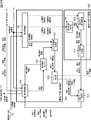
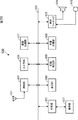
図1は、画像符号化装置の主な構成例を示すブロック図である。
<1. First Embodiment>
[Image encoding device]
FIG. 1 is a block diagram illustrating a main configuration example of an image encoding device.
図1に示される画像符号化装置100は、H.264及びMPEG(Moving Picture Experts Group)4 Part10(AVC(Advanced Video Coding))符号化方式のように、予測処理を用いて画像データを符号化する。
The
図1に示されるように画像符号化装置100は、A/D変換部101、画面並べ替えバッファ102、演算部103、直交変換部104、量子化部105、可逆符号化部106、および蓄積バッファ107を有する。また、画像符号化装置100は、逆量子化部108、逆直交変換部109、演算部110、ループフィルタ111、フレームメモリ112、選択部113、イントラ予測部114、動き予測・補償部115、予測画像選択部116、およびレート制御部117を有する。
As shown in FIG. 1, the
さらに、画像符号化装置100は、重み付け予測部121および重みモード判定部122を有する。
Furthermore, the
A/D変換部101は、入力された画像データをA/D変換し、変換後の画像データ(デジタルデータ)を、画面並べ替えバッファ102に供給し、記憶させる。画面並べ替えバッファ102は、記憶した表示の順番のフレームの画像を、GOP(Group Of Picture)に応じて、符号化のためのフレームの順番に並べ替え、フレームの順番を並び替えた画像を、演算部103に供給する。また、画面並べ替えバッファ102は、フレームの順番を並び替えた画像を、イントラ予測部114および動き予測・補償部115にも供給する。
The A /
演算部103は、画面並べ替えバッファ102から読み出された画像から、予測画像選択部116を介してイントラ予測部114若しくは動き予測・補償部115から供給される予測画像を減算し、その差分情報を直交変換部104に出力する。
The
例えば、イントラ符号化が行われる画像の場合、演算部103は、画面並べ替えバッファ102から読み出された画像から、イントラ予測部114から供給される予測画像を減算する。また、例えば、インター符号化が行われる画像の場合、演算部103は、画面並べ替えバッファ102から読み出された画像から、動き予測・補償部115から供給される予測画像を減算する。
For example, in the case of an image on which intra coding is performed, the
直交変換部104は、演算部103から供給される差分情報に対して、離散コサイン変換やカルーネン・レーベ変換等の直交変換を施す。なお、この直交変換の方法は任意である。直交変換部104は、その変換係数を量子化部105に供給する。
The
量子化部105は、直交変換部104から供給される変換係数を量子化する。量子化部105は、レート制御部117から供給される符号量の目標値に関する情報に基づいて量子化パラメータを設定し、その量子化を行う。なお、この量子化の方法は任意である。量子化部105は、量子化された変換係数を可逆符号化部106に供給する。
The
可逆符号化部106は、量子化部105において量子化された変換係数を、任意の符号化方式で符号化する。係数データは、レート制御部117の制御の下で量子化されているので、この符号量は、レート制御部117が設定した目標値となる(若しくは目標値に近似する)。
The
また、可逆符号化部106は、イントラ予測のモードを示す情報等を含むイントラ予測情報をイントラ予測部114から取得し、インター予測のモードを示す情報や動きベクトル情報などを含むインター予測情報を動き予測・補償部115から取得する。さらに、可逆符号化部106は、ループフィルタ111において使用されたフィルタ係数等を取得する。
Further, the
可逆符号化部106は、これらの各種情報を任意の符号化方式で符号化し、符号化データのヘッダ情報の一部とする(多重化する)。可逆符号化部106は、符号化して得られた符号化データを蓄積バッファ107に供給して蓄積させる。
The
可逆符号化部106の符号化方式としては、例えば、可変長符号化または算術符号化等が挙げられる。可変長符号化としては、例えば、H.264/AVC方式で定められているCAVLC(Context-Adaptive Variable Length Coding)などが挙げられる。算術符号化としては、例えば、CABAC(Context-Adaptive Binary Arithmetic Coding)などが挙げられる。
Examples of the encoding scheme of the
蓄積バッファ107は、可逆符号化部106から供給された符号化データを、一時的に保持する。蓄積バッファ107は、所定のタイミングにおいて、保持している符号化データを、ビットストリームとして、例えば、後段の図示せぬ記録装置(記録媒体)や伝送路などに出力する。
The
また、量子化部105において量子化された変換係数は、逆量子化部108にも供給される。逆量子化部108は、その量子化された変換係数を、量子化部105による量子化に対応する方法で逆量子化する。この逆量子化の方法は、量子化部105による量子化処理に対応する方法であればどのような方法であってもよい。逆量子化部108は、得られた変換係数を、逆直交変換部109に供給する。
The transform coefficient quantized by the
逆直交変換部109は、逆量子化部108から供給された変換係数を、直交変換部104による直交変換処理に対応する方法で逆直交変換する。この逆直交変換の方法は、直交変換部104による直交変換処理に対応する方法であればどのようなものであってもよい。逆直交変換された出力(局所的に復元された差分情報)は、演算部110に供給される。
The inverse
演算部110は、逆直交変換部109から供給された逆直交変換結果、すなわち、局所的に復元された差分情報に、予測画像選択部116を介してイントラ予測部114若しくは動き予測・補償部115から供給される予測画像を加算し、局所的に再構成された画像(以下、再構成画像と称する)を得る。その再構成画像は、ループフィルタ111またはフレームメモリ112に供給される。
The
ループフィルタ111は、デブロックフィルタや適応ループフィルタ等を含み、演算部110から供給される復号画像に対して適宜フィルタ処理を行う。例えば、ループフィルタ111は、復号画像に対してデブロックフィルタ処理を行うことにより復号画像のブロック歪を除去する。また、例えば、ループフィルタ111は、そのデブロックフィルタ処理結果(ブロック歪みの除去が行われた復号画像)に対して、ウィナーフィルタ(Wiener Filter)を用いてループフィルタ処理を行うことにより画質改善を行う。
The loop filter 111 includes a deblock filter, an adaptive loop filter, and the like, and appropriately performs a filtering process on the decoded image supplied from the
なお、ループフィルタ111が、復号画像に対して任意のフィルタ処理を行うようにしてもよい。また、ループフィルタ111は、必要に応じて、フィルタ処理に用いたフィルタ係数等の情報を可逆符号化部106に供給し、それを符号化させるようにすることもできる。
Note that the loop filter 111 may perform arbitrary filter processing on the decoded image. Further, the loop filter 111 can supply information such as filter coefficients used for the filter processing to the
ループフィルタ111は、フィルタ処理結果(以下、復号画像と称する)をフレームメモリ112に供給する。
The loop filter 111 supplies a filter processing result (hereinafter referred to as a decoded image) to the
フレームメモリ112は、演算部110から供給される再構成画像と、ループフィルタ111から供給される復号画像とをそれぞれ記憶する。フレームメモリ112は、所定のタイミングにおいて、若しくは、イントラ予測部114等の外部からの要求に基づいて、記憶している再構成画像を、選択部113を介して、イントラ予測部114に供給する。また、フレームメモリ112は、所定のタイミングにおいて、若しくは、動き予測・補償部115等の外部からの要求に基づいて、記憶している復号画像を、選択部113を介して、動き予測・補償部115に供給する。
The
選択部113は、フレームメモリ112から出力される画像の供給先を示す。例えば、イントラ予測の場合、選択部113は、フレームメモリ112からフィルタ処理されていない画像(再構成画像)を読み出し、周辺画素として、イントラ予測部114に供給する。
The
また、例えば、インター予測の場合、選択部113は、フレームメモリ112からフィルタ処理された画像(復号画像)を読み出し、参照画像として、それを動き予測・補償部115に供給する。
For example, in the case of inter prediction, the
イントラ予測部114は、フレームメモリ112から、処理対象領域の周辺に位置する周辺領域の画像(周辺画像)を取得すると、その周辺画像の画素値を用いて、基本的にプレディクションユニット(PU)を処理単位として予測画像を生成するイントラ予測(画面内予測)を行う。イントラ予測部114は、予め用意された複数のモード(イントラ予測モード)でこのイントラ予測を行う。
When the
イントラ予測部114は、候補となる全てのイントラ予測モードで予測画像を生成し、画面並べ替えバッファ102から供給される入力画像を用いて各予測画像のコスト関数値を評価し、最適なモードを選択する。イントラ予測部114は、最適なイントラ予測モードを選択すると、その最適なモードで生成された予測画像を、予測画像選択部116に供給する。
The
また、イントラ予測部114は、最適なイントラ予測モード等、イントラ予測に関する情報を含むイントラ予測情報を、適宜可逆符号化部106に供給し、符号化させる。
The
動き予測・補償部115は、画面並べ替えバッファ102から供給される入力画像と、フレームメモリ112から供給される参照画像とを用いて、基本的にPUを処理単位として、動き予測(インター予測)を行い、検出された動きベクトルに応じて動き補償処理を行い、予測画像(インター予測画像情報)を生成する。動き予測・補償部115は、予め用意された複数のモード(インター予測モード)でこのようなインター予測を行う。
The motion prediction /
動き予測・補償部115は、候補となる全てのインター予測モードで予測画像を生成し、各予測画像のコスト関数値を評価し、最適なモードを選択する。動き予測・補償部115は、最適なインター予測モードを選択すると、その最適なモードで生成された予測画像を、予測画像選択部116に供給する。
The motion prediction /
また、動き予測・補償部115は、最適なインター予測モード等、インター予測に関する情報を含むインター予測情報を可逆符号化部106に供給し、符号化させる。
In addition, the motion prediction /
予測画像選択部116は、演算部103や演算部110に供給する予測画像の供給元を選択する。例えば、イントラ符号化の場合、予測画像選択部116は、予測画像の供給元としてイントラ予測部114を選択し、そのイントラ予測部114から供給される予測画像を演算部103や演算部110に供給する。また、例えば、インター符号化の場合、予測画像選択部116は、予測画像の供給元として動き予測・補償部115を選択し、その動き予測・補償部115から供給される予測画像を演算部103や演算部110に供給する。
The predicted
レート制御部117は、蓄積バッファ107に蓄積された符号化データの符号量に基づいて、オーバーフローあるいはアンダーフローが発生しないように、量子化部105の量子化動作のレートを制御する。
The
重み付け予測部121は、動き予測・補償部115が行うインター予測モードにおいて、重み付け予測に関する処理を行う。重みモード判定部122は、重み付け予測部121により行われる重み付け予測の最適なモードを判定する。
The
重み付け予測部121および重みモード判定部122は、スライスよりも小さな単位を処理単位として、重み付け予測のモードを制御する。このようにすることにより、画像符号化装置100は、重み付け予測の予測精度を向上させ、符号化効率を向上させることができる。
The
[1/4画素精度動き予測]
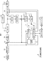
図2は、AVC符号化方式において規定されている、1/4画素精度の動き予測・補償処理の様子の例を説明する図である。図2において、各四角は、画素を示している。その内、Aはフレームメモリ112に格納されている整数精度画素の位置を示し、b,c,dは、1/2画素精度の位置を示し、e1,e2,e3は1/4画素精度の位置を示している。
[1/4 pixel precision motion prediction]
FIG. 2 is a diagram for explaining an example of a state of motion prediction / compensation processing with 1/4 pixel accuracy defined in the AVC encoding method. In FIG. 2, each square represents a pixel. Among them, A indicates the position of integer precision pixels stored in the
以下においては、関数Clip1()を以下の式(1)のように定義する。 In the following, the function Clip1 () is defined as in the following equation (1).

例えば、入力画像が8ビット精度である場合、式(1)のmax_pixの値は255となる。 For example, when the input image has 8-bit precision, the value of max_pix in Expression (1) is 255.
b及びdの位置における画素値は、6tapのFIRフィルタを用いて、以下の式(2)および式(3)のように生成される。 The pixel values at the positions b and d are generated as in the following expressions (2) and (3) using a 6 tap FIR filter.
![]()
![]()
![]()
![]()
cの位置における画素値は、水平方向及び垂直方向に6tapのFIRフィルタを適用し、以下の式(4)乃至式(6)のように生成される。 The pixel value at the position c is generated as shown in the following equations (4) to (6) by applying a 6 tap FIR filter in the horizontal direction and the vertical direction.
![]()
もしくは、
![]()
![]()
![]()
Or
![]()
![]()
なお、Clip処理は、水平方向及び垂直方向の積和処理の両方を行った後、最後に1度のみ行われる。 Note that the Clip process is performed only once at the end after performing both the horizontal and vertical product-sum processes.
e1乃至e3は、以下の式(7)乃至式(9)のように、線形内挿により生成される。 e1 to e3 are generated by linear interpolation as in the following formulas (7) to (9).
![]()
![]()
![]()
![]()
![]()
![]()
[マクロブロック]
また、MPEG2においては、動き予測・補償処理の単位は、フレーム動き補償モードの場合には16×16画素、フィールド動き補償モードの場合には第一フィールド、第二フィールドのそれぞれに対し、16×8画素を単位として動き予測・補償処理が行なわれる。
[Macro block]
In MPEG2, the unit of motion prediction / compensation processing is 16 × 16 pixels in the frame motion compensation mode, and 16 × 16 for each of the first field and the second field in the field motion compensation mode. Motion prediction / compensation processing is performed in units of 8 pixels.
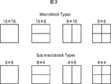
これに対し、AVCにおいては、図3に示されるように、16×16画素により構成される1つのマクロブロックを、16×16、16×8、8×16若しくは8×8のいずれかのパーティションに分割し、サブマクロブロック毎に、互いに独立した動きベクトル情報を持つことが可能である。更に、8×8パーティションに関しては、図3に示されるとおり、8×8、8×4、4×8、4×4のいずれかのサブマクロブロックに分割し、それぞれ独立した動きベクトル情報を持つことが可能である。 On the other hand, in AVC, as shown in FIG. 3, one macroblock composed of 16 × 16 pixels is divided into any partition of 16 × 16, 16 × 8, 8 × 16, or 8 × 8. It is possible to have independent motion vector information for each sub macroblock. Further, as shown in FIG. 3, the 8 × 8 partition is divided into 8 × 8, 8 × 4, 4 × 8, and 4 × 4 sub-macroblocks and has independent motion vector information. It is possible.
しかしながら、AVC画像符号化方式において、MPEG2の場合と同様に、かかるような動き予測・補償処理が行なわれるようにすると、膨大な動きベクトル情報が生成されてしまう恐れがあった。そして、その生成された動きベクトル情報をこのまま符号化することは、符号化効率の低下を招く恐れがあった。 However, in the AVC image encoding method, if such motion prediction / compensation processing is performed as in the case of MPEG2, a large amount of motion vector information may be generated. Then, encoding the generated motion vector information as it is may cause a decrease in encoding efficiency.
[動きベクトルのメディアン予測]
かかる問題を解決する手法として、AVC画像符号化においては、以下のような手法により、動きベクトルの符号化情報の低減が実現されている。
[Median prediction of motion vectors]
As a technique for solving this problem, in AVC image encoding, reduction of motion vector encoding information is realized by the following technique.
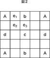
図4に示される各直線は、動き補償ブロックの境界を示している。また、図4において、Eはこれから符号化されようとしている当該動き補償ブロックを示し、A乃至Dは、それぞれ、既に符号化済の、Eに隣接する動き補償ブロックを示す。 Each straight line shown in FIG. 4 indicates the boundary of the motion compensation block. In FIG. 4, E indicates the motion compensation block that is about to be encoded, and A through D indicate motion compensation blocks that are already encoded and that are adjacent to E.
今、X=A,B,C,D,Eとして、Xに対する動きベクトル情報を、mvxとする。 Now, assuming that X = A, B, C, D, E, the motion vector information for X is mv x .
まず、動き補償ブロックA,B、およびCに関する動きベクトル情報を用い、動き補償ブロックEに対する予測動きベクトル情報pmvEを、メディアンオペレーションにより、以下の式(10)のように生成する。 First, motion vector information on motion compensation blocks A, B, and C is used, and predicted motion vector information pmv E for motion compensation block E is generated by the median operation as shown in the following equation (10).
![]()
![]()
動き補償ブロックCに関する情報が、画枠の端である等の理由により利用不可能(unavailable)である場合、動き補償ブロックDに関する情報で代用される。 If the information about the motion compensation block C is unavailable because it is at the edge of the image frame or the like, the information about the motion compensation block D is substituted.
画像圧縮情報に、動き補償ブロックEに対する動きベクトル情報として符号化されるデータmvdEは、pmvEを用いて、以下の式(11)のように生成される。 Data mvd E encoded as motion vector information for the motion compensation block E in the image compression information is generated as shown in the following equation (11) using pmv E.
![]()
![]()
なお、実際の処理は、動きベクトル情報の水平方向および垂直方向のそれぞれの成分に対して、独立に処理が行なわれる。 Note that the actual processing is performed independently for each of the horizontal and vertical components of the motion vector information.
[マルチ参照フレーム]
また、AVCにおいては、Multi-Reference Frame(マルチ(複数)参照フレーム)という、MPEG2やH.263等、従来の画像符号化方式では規定されていなかった方式が規定されている。
[Multi-reference frame]
In AVC, a method called Multi-Reference Frame (multi-reference frame), such as MPEG2 and H.263, which has not been specified in the conventional image encoding method is specified.
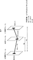
図5を用いて、AVCにおいて規定されている、マルチ参照フレーム(Multi-Reference Frame)を説明する。 A multi-reference frame defined in AVC will be described with reference to FIG.
すなわち、MPEG-2やH.263においては、Pピクチャの場合、フレームメモリに格納された参照フレーム1枚のみを参照することにより動き予測・補償処理が行われていたが、AVCにおいては、図5に示されるように、複数の参照フレームがメモリに格納され、マクロブロック毎に、異なるメモリを参照することが可能である。 That is, in MPEG-2 and H.263, in the case of a P picture, motion prediction / compensation processing is performed by referring to only one reference frame stored in the frame memory. As shown in FIG. 5, a plurality of reference frames are stored in the memory, and it is possible to refer to different memories for each macroblock.
ところで、MPEG2やMPEG4においては、例えば、フェードシーンのように、動きが存在するが、明るさが変化するようなシーケンスにおいては、明るさの変化を吸収する符号化ツールが用意されていないため、符号化効率が低下する恐れがあった。 By the way, in MPEG2 and MPEG4, for example, in a sequence where there is motion, such as a fade scene, but the brightness changes, there is no encoding tool to absorb the change in brightness. There is a possibility that the coding efficiency may be lowered.
かかる問題を解決するため、AVC符号化方式においては、重み付け予測処理を行うことが可能である(非特許文献2参照)。すなわち、Pピクチャにおいては、Y0を動き補償予測信号すると、重み係数W0及びオフセット値をDとして、以下の式(12)のように予測信号が生成される。 In order to solve such a problem, it is possible to perform weighted prediction processing in the AVC encoding method (see Non-Patent Document 2). That is, in a P picture, when Y 0 is a motion compensated prediction signal, a prediction signal is generated as shown in the following equation (12), where D is a weighting factor W 0 and an offset value.
W0×Y0+D ・・・(12) W 0 × Y 0 + D (12)
また、Bピクチャにおいては、List0およびList1に対する動き補償予測信号をY0及びY1として、それぞれに対する重み係数をW0及びW1、及びオフセットをDとして、以下の式(13)のように予測信号が生成される。 Also, in the B picture, the motion compensated prediction signals for List0 and List1 are set as Y 0 and Y 1 , the weighting coefficients for each are set as W 0 and W 1 , and the offset is set as D, as shown in the following equation (13) A signal is generated.
W0×Y0+W1×Y1+D ・・・(13) W 0 × Y 0 + W 1 × Y 1 + D (13)
AVCにおいては、スライス単位で、上記の重み付け予測を用いる・用いないを指定することが可能である。 In AVC, it is possible to specify whether or not to use the above weighted prediction for each slice.
また、AVCにおいては、重み付け予測として、スライスヘッダに、WおよびDを伝送する、Explicit Mode、及び、当該ピクチャと、参照ピクチャにおける、時間軸上での距離から、Wを算出するImplicit Modeとが規定されている。 In AVC, as weighted prediction, there are Explicit Mode for transmitting W and D to the slice header, and Implicit Mode for calculating W from the distance between the picture and the reference picture on the time axis. It is prescribed.
Pピクチャにおいては、Explicit Modeのみを用いることができる。 In P picture, only Explicit Mode can be used.
Bピクチャにおいては、Explicit ModeとImplicit Modeの両方を用いることができる。 In B picture, both Explicit Mode and Implicit Mode can be used.
図7に、Bピクチャにおける、Implicit Modeである場合の、W及びDの算出方法を示す。 FIG. 7 shows a calculation method of W and D in the case of Implicit Mode in a B picture.
なお、AVCの場合、時間距離情報であるtb及びtdに相当する情報が存在しないため、POC(Picture Order Count)を用いる。 In the case of AVC, POC (Picture Order Count) is used because there is no information corresponding to time distance information tb and td.
また、AVCにおいて、重み付け予測(Weighted Prediction)は、スライス単位で適用することができる。さらに、非特許文献2には、ブロック単位で重み付け予測(Weighted Prediction)を適用する方法(Intensity Compensation)も提案されている。
In AVC, weighted prediction can be applied in units of slices. Furthermore,
[動きベクトルの選択]
ところで、図1に示した画像符号化装置100により、符号化効率の高い画像圧縮情報を得るためには、動きベクトル及びマクロブロックモードをどのような処理により選択するかが重要である。
[Select motion vector]
By the way, in order to obtain image compression information with high encoding efficiency by the
処理の一例として、http://iphome.hhi.de/suehring/tml/index.htmにおいて公開されている、JM(Joint Model)と呼ばれるreference softwareに実装されている手法を挙げることが出来る。 As an example of processing, a method implemented in reference software called JM (Joint Model) published at http://iphome.hhi.de/suehring/tml/index.htm can be cited.
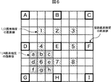
以下では、図6を用いて、JMにおいて実装されている動き探索方式について説明する。図6において、A乃至Iは、整数画素精度の画素値、1乃至8は、E周りの1/2画素精度の画素値、a乃至hは、6周りの、1/4画素精度の画素値である。 Hereinafter, a motion search method implemented in JM will be described with reference to FIG. In FIG. 6, A to I are pixel values with integer pixel accuracy, 1 to 8 are pixel values with 1/2 pixel accuracy around E, and a to h are pixel values with 1/4 pixel accuracy around 6. It is.
第1のステップとして、所定の探索範囲内において、SAD(Sum of Absolute Difference)等のコスト関数を最小にする、整数画素精度の動きベクトルを求める。図6の例において、Eが、その整数画素精度の動きベクトルに対応する画素であるとする。 As a first step, an integer pixel precision motion vector that minimizes a cost function such as SAD (Sum of Absolute Difference) within a predetermined search range is obtained. In the example of FIG. 6, it is assumed that E is a pixel corresponding to a motion vector with integer pixel accuracy.
第2のステップとして、E及び、E周りの1/2画素精度1乃至8のうち、コスト関数を最小にする画素値を求め、これを1/2画素精度の最適動きベクトルとする。図6の例において、6が、その1/2画素精度の最適動きベクトルに対応する画素であるとする。
As a second step, a pixel value that minimizes the cost function is obtained from E and ½
第3のステップとして、6及び、6周りの、1/4画素精度a乃至hのうち、コスト関数を最小にする画素値を求め、これを1/4画素精度の最適動きベクトルとする。 As a third step, a pixel value that minimizes the cost function is obtained from the ¼ pixel accuracy a to h around 6 and 6, and this is set as an ¼ pixel accuracy optimal motion vector.
[予測モードの選択]
また、以下では、JMにおいて定められているモード判定方式について述べる。
[Select prediction mode]
In the following, the mode determination method defined in JM will be described.
JMにおいては、以下に述べる、High Complexity Modeと、Low Complexity Modeの2通りのモード判定方法を選択することが可能である。どちらも、それぞれの予測モードに関するコスト関数値を算出し、これを最小にする予測モードを当該ブロック乃至マクロブロックに対する最適モードとして選択する。 In JM, it is possible to select the following two mode determination methods, High Complexity Mode and Low Complexity Mode. In both cases, the cost function value for each prediction mode is calculated, and the prediction mode that minimizes the cost function value is selected as the optimum mode for the block or macroblock.
High Complexity Modeにおけるコスト関数は、以下の式(14)のように示される。 The cost function in High Complexity Mode is shown as the following formula (14).
Cost(Mode∈Ω) = D + λ*R ・・・(14) Cost (Mode∈Ω) = D + λ * R (14)
ここで、Ωは、当該ブロック乃至マクロブロックを符号化するための候補モードの全体集合、Dは、当該予測モードで符号化した場合の、復号画像と入力画像の差分エネルギーである。λは、量子化パラメータの関数として与えられるLagrange未定乗数である。Rは、直交変換係数を含んだ、当該モードで符号化した場合の総符号量である。 Here, Ω is the entire set of candidate modes for encoding the block or macroblock, and D is the difference energy between the decoded image and the input image when encoded in the prediction mode. λ is a Lagrange undetermined multiplier given as a function of the quantization parameter. R is the total code amount when encoding is performed in this mode, including orthogonal transform coefficients.
つまり、High Complexity Modeでの符号化を行うには、上記パラメータD及びRを算出するため、全ての候補モードにより、一度、仮エンコード処理を行う必要があり、より高い演算量を要する。 In other words, in order to perform encoding in the High Complexity Mode, the parameters D and R are calculated. Therefore, it is necessary to perform a temporary encoding process once in all candidate modes, which requires a higher calculation amount.
Low Complexity Modeにおけるコスト関数は、以下の式(15)のように示される。 The cost function in Low Complexity Mode is shown as the following formula (15).
Cost(Mode∈Ω) = D + QP2Quant(QP) * HeaderBit ・・・(15) Cost (Mode∈Ω) = D + QP2Quant (QP) * HeaderBit (15)
ここで、Dは、High Complexity Modeの場合と異なり、予測画像と入力画像の差分エネルギーとなる。QP2Quant(QP)は、量子化パラメータQPの関数として与えられ、HeaderBitは、直交変換係数を含まない、動きベクトルや、モードといった、Headerに属する情報に関する符号量である。 Here, unlike the case of High Complexity Mode, D is the difference energy between the predicted image and the input image. QP2Quant (QP) is given as a function of the quantization parameter QP, and HeaderBit is a code amount related to information belonging to Header, such as a motion vector and mode, which does not include an orthogonal transform coefficient.
すなわち、Low Complexity Modeにおいては、それぞれの候補モードに関して、予測処理を行う必要があるが、復号画像までは必要ないため、符号化処理まで行う必要はない。このため、High Complexity Modeより低い演算量での実現が可能である。 That is, in Low Complexity Mode, it is necessary to perform prediction processing for each candidate mode, but it is not necessary to perform decoding processing because it is not necessary to perform decoding processing. For this reason, realization with a calculation amount lower than High Complexity Mode is possible.
[コーディングユニット]
ところで、マクロブロックサイズを16画素×16画素とするのは、次世代符号化方式の対象となるような、UHD(Ultra High Definition;4000画素×2000画素)といった大きな画枠に対しては、最適ではない。
[Coding unit]
By the way, the macro block size of 16 pixels × 16 pixels is optimal for a large image frame such as UHD (Ultra High Definition; 4000 pixels × 2000 pixels), which is a target of the next generation encoding method. is not.
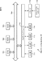
そこで、AVCにおいては、図3に示されるように、マクロブロックとサブマクロブロックによる階層構造が規定されているが、例えば、HEVC(High Efficiency Video Coding)においては、図8に示されるように、コーディングユニット(CU(Coding Unit))が規定されている。 Therefore, in AVC, as shown in FIG. 3, a hierarchical structure is defined by macroblocks and sub-macroblocks. For example, in HEVC (High Efficiency Video Coding), as shown in FIG. A coding unit (CU (Coding Unit)) is defined.
CUは、Coding Tree Block(CTB)とも呼ばれ、AVCにおけるマクロブロックと同様の役割を果たす、ピクチャ単位の画像の部分領域である。後者は、16×16画素の大きさに固定されているのに対し、前者の大きさは固定されておらず、それぞれのシーケンスにおいて、画像圧縮情報中において指定されることになる。 A CU is also called a Coding Tree Block (CTB), and is a partial area of a picture unit image that plays the same role as a macroblock in AVC. The latter is fixed to a size of 16 × 16 pixels, whereas the size of the former is not fixed, and is specified in the image compression information in each sequence.
例えば、出力となる符号化データに含まれるシーケンスパラメータセット(SPS(Sequence Parameter Set))において、CUの最大サイズ(LCU(Largest Coding Unit))と最小サイズ((SCU(Smallest Coding Unit))が規定される。 For example, in the sequence parameter set (SPS (Sequence Parameter Set)) included in the output encoded data, the maximum size (LCU (Largest Coding Unit)) and minimum size ((SCU (Smallest Coding Unit)) of the CU are specified. Is done.
それぞれのLCU内においては、SCUのサイズを下回らない範囲で、split-flag=1とすることにより、より小さなサイズのCUに分割することができる。図8の例では、LCUの大きさが128であり、最大階層深度が5となる。2N×2Nの大きさのCUは、split_flagの値が「1」である時、1つ下の階層となる、N×Nの大きさのCUに分割される。 Within each LCU, split-flag = 1 can be divided into smaller CUs within a range that does not fall below the SCU size. In the example of FIG. 8, the LCU size is 128 and the maximum hierarchical depth is 5. When the value of split_flag is “1”, the 2N × 2N size CU is divided into N × N size CUs that are one level below.
更に、CUは、イントラ若しくはインター予測の処理単位となる領域(ピクチャ単位の画像の部分領域)であるプレディクションユニット(Prediction Unit(PU))に分割され、また、直交変換の処理単位となる領域(ピクチャ単位の画像の部分領域)である、トランスフォームユニット(Transform Unit(TU))に分割される。現在、HEVCにおいては、4×4及び8×8に加え、16×16及び32×32直交変換を用いることが可能である。 Furthermore, CU is divided into prediction units (Prediction Units (PU)) that are regions (partial regions of images in units of pictures) that are processing units for intra or inter prediction, and are regions that are processing units for orthogonal transformation It is divided into transform units (Transform Units (TU)), which are (partial regions of images in picture units). Currently, in HEVC, it is possible to use 16 × 16 and 32 × 32 orthogonal transforms in addition to 4 × 4 and 8 × 8.
以上のHEVCのように、CUを定義し、そのCUを単位として各種処理を行うような符号化方式の場合、AVCにおけるマクロブロックはLCUに相当すると考えることができる。ただし、CUは図8に示されるように階層構造を有するので、その最上位階層のLCUのサイズは、例えば128×128画素のように、AVCのマクロブロックより大きく設定されることが一般的である。 In the case of an encoding method in which a CU is defined and various processes are performed in units of the CU as in the above HEVC, it can be considered that a macroblock in AVC corresponds to an LCU. However, since the CU has a hierarchical structure as shown in FIG. 8, the size of the LCU in the highest hierarchy is generally set larger than the AVC macroblock, for example, 128 × 128 pixels. is there.
なお、以下において、上述したマクロブロック、サブマクロブロック、CU、PU、およびTU等の画像単位を、単に「領域」と称する場合もある。つまり、イントラ若しくはインター予測の処理単位を説明する場合の「領域」は、これらの画像単位を含む任意の画像単位である。また、状況に応じて、「領域」が、これらの画像単位の一部を含まなくてもよいし、これら以外の画像単位を含むようにしてもよい。 In the following, image units such as the above-described macroblocks, sub-macroblocks, CU, PU, and TU may be simply referred to as “regions”. That is, the “region” in the case of describing the intra or inter prediction processing unit is an arbitrary image unit including these image units. Further, depending on the situation, the “region” may not include a part of these image units, or may include other image units.
[画像の内容による重み付き予測の精度の低下]
ところで、画像によっては、一部において輝度変化があるが、その他の一部では、輝度変化がない、若しくは、輝度変化が一様ではないというものも存在する。例えば、レターボックス付きの画像や、図9に示されるようなピラーボックス付きの画像のように、画像の一部が、黒画像(黒色で塗りつぶされた画像)等によって輝度が変化しない画像により構成されるものがある。また、額縁画像やピクチャインピクチャ等のような画像も存在する。
[Decrease in accuracy of weighted prediction due to image content]
By the way, although there is a luminance change in some images, there are some in which there is no luminance change or luminance variation is not uniform in the other part. For example, a part of the image, such as an image with a letter box or an image with a pillar box as shown in FIG. 9, is composed of an image whose luminance does not change due to a black image (an image painted in black) or the like. There is something to be done. There are also images such as frame images and picture-in-pictures.
AVCの重み付け予測の場合、これらのような画像に対しても、画像全体に一様に重み付け予測を行うので、輝度変化が無い部分において予測精度が低減し、符号化効率が低減してしまう恐れがあった。 In the case of AVC weighted prediction, even for such images, weighted prediction is performed uniformly on the entire image, so that prediction accuracy may be reduced in portions where there is no change in luminance, and coding efficiency may be reduced. was there.
そこで、重み付け予測部121および重みモード判定部122は、AVCの重み付け予測の場合よりも小さな画像単位で、例えば、重み付け予測を行うか否か等、重み付け予測のモード(重みモード)を制御するようにする。
Therefore, the
[動き予測・補償部、重み付け予測部、重みモード判定部]
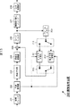
図10は、図1の動き予測・補償部115、重み付け予測部121、および重みモード判定部122の主な構成例を示すブロック図である。
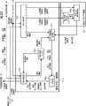
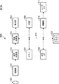
[Motion prediction / compensation unit, weighted prediction unit, weight mode determination unit]
FIG. 10 is a block diagram illustrating a main configuration example of the motion prediction /
図11に示されるように、動き予測・補償部115は、動き探索部151、コスト関数値生成部152、モード判定部153、動き補償部154、および動き情報バッファ155を有する。
As illustrated in FIG. 11, the motion prediction /
また、重み付け予測部121は、重み係数決定部161および重み付け動き補償部162を有する。
Further, the
動き探索部151は、画面並べ替えバッファ102から取得した入力画像画素値と、フレームメモリ112から取得した参照画像画素値とを用いて、全てのインター予測モードで予測処理単位の領域毎に動き探索を行い、動き情報を求め、コスト関数値生成部152に供給する。この予測処理単位の領域は、少なくともAVCの重み付け予測の処理単位であるスライスよりも小さい画像単位であり、その大きさはインター予測モード毎に異なる。
The
また、動き探索部151は、各インター予測モードの動き探索に利用した入力画像画素値と参照画像画素値とを重み付け予測部121の重み係数決定部161に供給する。
In addition, the
さらに、動き探索部151は、全てのインター予測モードについて、求めた各インター予測モードの動き情報を用いて重み付けを用いない動き補償(重み付けOFFの動き補償とも称する)を行い、重み付け予測OFFの予測画像を生成する。つまり、動き探索部151は、予測処理単位の領域毎に重み付け予測OFFの予測画像を生成する。動き探索部151は、その予測画像画素値を入力画像画素値とともに重み付け動き補償部162に供給する。
Further, the
重み付け予測部121の重み係数決定部161は、L0およびL1の重み係数(WやD等)を決定する。より具体的には、重み係数決定部161は、全てのインター予測モードについて、動き探索部151から供給される入力画像画素値および参照画像画素値に基づいて、L0及びL1の重み係数を決定する。つまり、重み係数決定部161は、予測処理単位の領域毎に重み係数を決定する。重み係数決定部161は、その重み係数を、入力画像および参照画像とともに重み付け動き補償部162に供給する。
The weighting
重み付け動き補償部162は、予測処理単位の領域毎に重み付けを用いた動き補償(重み付けONの動き補償とも称する)を行う。また、重み付け動き補償部162は、全ての予測モード、並びに、全ての重みモード(重み付けに関するモード)について、予測画像と入力画像の差分画像を生成し、その差分画像画素値を重みモード判定部122に供給する。
The weighted motion compensation unit 162 performs motion compensation using weighting for each region of the prediction processing unit (also referred to as motion compensation with weighting ON). In addition, the weighted motion compensation unit 162 generates a difference image between the prediction image and the input image for all prediction modes and all the weight modes (modes related to weighting), and uses the difference image pixel value as the weight
より具体的には、重み付け動き補償部162は、重み係数決定部161から供給された重み係数や各画像を用いて、全てのインター予測モードについて、重み付けONの動き補償を行い、重み付けONの予測画像を生成する。つまり、重み付け動き補償部162は、予測処理単位の領域毎に重み付けONの予測画像を生成する。そして、重み付け動き補償部162は、予測処理単位の領域毎に、重み付けONの予測画像と入力画像との差分画像(重み付けONの差分画像)を生成する。
More specifically, the weighted motion compensation unit 162 performs weighted ON motion compensation for all inter prediction modes using the weighting factor and each image supplied from the weighting
また、重み付け動き補償部162は、全てのインター予測モードについて、動き探索部151から供給された重み付けOFFの予測画像と入力画像との差分画像(重み付けOFFの差分画像)を生成する。つまり、重み付け動き補償部162は、予測処理単位の領域毎に重み付けOFFの差分画像を生成する。
Also, the weighted motion compensation unit 162 generates a difference image (a weighted OFF difference image) between the weighted OFF predicted image supplied from the
重み付け動き補償部162は、全てのインター予測モードについて、予測処理単位の領域毎の、重み付けONの差分画像と、重み付けOFFの差分画像とを重みモード判定部122に供給する。
The weighting motion compensation unit 162 supplies the weighting ON difference image and the weighting OFF difference image to the weighting
また、重み付け動き補償部162は、予測処理単位の領域毎に、重みモード判定部122から供給される最適重みモード情報が示す重みモードの情報を、動き予測・補償部115のコスト関数値生成部152に供給する。
Also, the weighted motion compensation unit 162 uses the weight mode information indicated by the optimal weight mode information supplied from the weight
より具体的には、重み付け動き補償部162は、全てのインター予測モードについて、重みモード判定部122から供給される最適重みモード情報と、その重みモードの差分画像画素値(重み付けONの差分画像、若しくは、重み付けOFFの差分画像)と、その重みモードの重み係数(重み付けOFFのモードの場合、重み係数は不要)とを、コスト関数値生成部152に供給する。
More specifically, the weighted motion compensation unit 162, for all inter prediction modes, the optimum weight mode information supplied from the weight
重みモード判定部122は、予測処理単位の領域毎に、複数の重みモードのそれぞれの差分画像画素値を互いに比較し、最適な重みモードを判定する。
The weight
より具体的には、重みモード判定部122は、重み付け動き補償部162から供給された重み付けONの差分画像画素値と重み付けOFFの差分画像画素値とを比較する。この差分画像画素値が小さい(すなわち入力画像との差分が小さい)方が、予測精度が高い。したがって、重みモード判定部122は、画素値が最も小さい差分画像に対応する重みモードを最適な重みモードに決定する。つまり、重みモード判定部122は、重み付けONと重み付けOFFの2つのモードの内、予測精度が高い(すなわち入力画像との差分が小さい)方を最適な重みモードとして判定する。
More specifically, the weighting
重みモード判定部122は、その判定結果を、最適と選択された重みモードを示す最適重みモード情報として、重み付け動き補償部162に供給する。
The weight
重みモード判定部122は、全てのインター予測モードについて、このように最適な重みモードを判定する。
The weight
コスト関数値生成部152は、予測処理単位の領域毎に、全てのインター予測モードについて、最適な重みモードのコスト関数値を算出する。
The cost function
より具体的には、コスト関数値生成部152は、重み付け動き補償部162から供給される、各インター予測モードの最適な重みモードの差分画像画素値のコスト関数値を算出する。コスト関数値生成部152は、算出したコスト関数値を、最適重みモード情報や重み係数(重み付けOFFのモードの場合、重み係数は不要)とともにモード判定部153に供給する。
More specifically, the cost function
また、コスト関数値生成部152は、予測処理単位の領域毎に、全てのインター予測モードについて、動き情報バッファ155から周辺動き情報を取得し、動き探索部151から供給された動き情報と、その周辺動き情報との差分(差分動き情報)を算出する。コスト関数値生成部152は、算出した各インター予測モードの差分動き情報をモード判定部153に供給する。
In addition, the cost function
モード判定部153は、予測処理単位の領域毎に、コスト関数値を最小にする予測モードを、処理対象領域に対する最適なインター予測モードとして判定する。
The
より具体的には、モード判定部153は、コスト関数値生成部152から供給されるコスト関数値が最小のインター予測モードを、その領域の最適なインター予測モードと判定する。モード判定部153は、この最適なインター予測モードを示す最適モード情報を、その最適なインター予測モードの、差分動き情報、最適重みモード情報、および重み係数(重み付けOFFのモードの場合、重み係数は不要)とともに、動き補償部154に供給する。
More specifically, the
動き補償部154は、予測処理単位の領域毎に、最適なインター予測モードの、最適な重みモードで、動き補償を行い、予測画像を生成する。
The
より具体的には、動き補償部154は、モード判定部153から、最適モード情報、差分動き情報、最適重みモード情報、および重み係数等の各種情報を取得する。また、動き補償部154は、その最適モード情報に示される最適なインター予測モードで、動き情報バッファ155から周辺動き情報を取得する。
More specifically, the
動き補償部154は、その周辺動き情報および差分動き情報を用いて、最適なインター予測モードの動き情報を生成する。動き補償部154は、その動き情報を用いて、その最適モード情報に示される最適なインター予測モードで、フレームメモリ112から参照画像画素値を取得する。
The
動き補償部154は、その参照画像と重み係数(重み付けOFFのモードの場合、重み係数は不要)を用いて、予測処理単位の領域毎に、最適な重みモードで動き補償を行い、予測画像を生成する。動き補償部154は、予測処理単位の領域毎に、生成した予測画像画素値を予測画像選択部116に供給し、演算部103において入力画像から減算させたり、演算部110において差分画像に加算させたりする。
The
また、動き補償部154は、予測処理単位の領域毎に、差分動き情報、最適モード情報、最適重みモード情報、および重み係数(重み付けOFFのモードの場合、重み係数は不要)等の、動き探索および動き補償に用いた各種情報を、可逆符号化部106に供給し、符号化させる。なお、Explicitモードの場合も、重み係数は、符号化されない。
In addition, the
以上のように、重みモード判定部122が、スライスよりも小さい画像単位毎に、最適な重みモードを示す最適重みモード情報を生成し、重み付け予測部121の重み付け動き補償部162が、スライスよりも小さい画像単位毎に、その最適重みモード情報を、動き予測・補償部115に供給し、動き予測・補償部115が、スライスよりも小さい画像単位毎に、最適な重みモードで動き補償を行って予測画像を生成するとともに、最適重みモード情報を復号側に伝送させる。
As described above, the weight
したがって、画像符号化装置100は、重み付け予測をより小さな領域毎に制御することができる。より具体的には、画像符号化装置100は、重み付け予測を行うか否かをより小さな領域毎に制御することができる。したがって、画像符号化装置100は、例えば、図9に示されるような、画像全体の輝度変化が一様でない画像を符号化する場合であっても、画像全体の輝度変化のある部分についてのみ重み付け予測を行うことができるので、輝度変化の無い部分が与える重み係数への影響を抑制することができ、重み付け予測の予測精度の低減を抑制することができる。したがって、画像符号化装置100は、符号化効率を向上させることができる。
Therefore, the
[符号化処理の流れ]
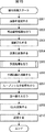
次に、以上のような画像符号化装置100により実行される各処理の流れについて説明する。最初に、図11のフローチャートを参照して、符号化処理の流れの例を説明する。
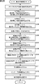
[Flow of encoding process]
Next, the flow of each process executed by the
ステップS101において、A/D変換部101は入力された画像をA/D変換する。ステップS102において、画面並べ替えバッファ102は、A/D変換された画像を記憶し、各ピクチャの表示する順番から符号化する順番への並べ替えを行う。
In step S101, the A /
ステップS103において、イントラ予測部114は、イントラ予測処理を行う。ステップS104において、動き予測・補償部115、重み付け予測部121、および動きベクトル精度判定部122は、インター動き予測処理を行う。ステップS105において、予測画像選択部116は、イントラ予測により生成された予測画像、および、インター予測により生成された予測画像の内、いずれか一方を選択する。
In step S103, the
ステップS106において、演算部103は、ステップS102の処理により並び替えられた画像と、ステップS105の処理により選択された予測画像との差分を演算する(差分画像を生成する)。生成された差分画像は元の画像に較べてデータ量が低減される。したがって、画像をそのまま符号化する場合に較べて、データ量を圧縮することができる。
In step S106, the
ステップS107において、直交変換部104は、ステップS106の処理により生成された差分画像を直交変換する。具体的には、離散コサイン変換、カルーネン・レーベ変換等の直交変換が行われ、直交変換係数が出力される。ステップS108において、量子化部105は、ステップS107の処理により得られた直交変換係数を量子化する。
In step S107, the
ステップS108の処理により量子化された差分画像は、次のようにして局部的に復号される。すなわち、ステップS109において、逆量子化部108は、ステップS108の処理により生成された量子化された直交変換係数(量子化係数とも称する)を量子化部105の特性に対応する特性で逆量子化する。ステップS110において、逆直交変換部109は、ステップS109の処理により得られた直交変換係数を、直交変換部104の特性に対応する特性で逆直交変換する。これにより差分画像が復元される。
The difference image quantized by the process of step S108 is locally decoded as follows. That is, in step S109, the
ステップS111において、演算部110は、ステップS105において選択された予測画像を、ステップS110において生成された差分画像に加算し、局部的に復号された復号画像(再構成画像)を生成する。ステップS112において、ループフィルタ111は、ステップS111の処理により得られた再構成画像に対して、デブロックフィルタ処理や適応ループフィルタ処理等を含むループフィルタ処理を適宜行い、復号画像を生成する。
In step S111, the
ステップS113において、フレームメモリ112は、ステップS112の処理により生成された復号画像、若しくは、ステップS111の処理により生成された再構成画像を記憶する。
In step S113, the
ステップS114において、可逆符号化部106は、ステップS108の処理により量子化された直交変換係数を符号化する。すなわち、差分画像に対して、可変長符号化や算術符号化等の可逆符号化が行われる。なお、可逆符号化部106は、予測に関する情報や、量子化に関する情報等を符号化し、ビットストリームに付加する。
In step S114, the
ステップS115において、蓄積バッファ107は、ステップS114の処理により得られたビットストリームを蓄積する。蓄積バッファ107に蓄積された符号化データは、適宜読み出され、伝送路や記録媒体を介して復号側に伝送される。
In step S115, the
ステップS116においてレート制御部117は、ステップS115の処理により蓄積バッファ107に蓄積された符号化データの符号量(発生符号量)に基づいて、オーバーフローあるいはアンダーフローが発生しないように、量子化部105の量子化動作のレートを制御する。
In step S116, the
ステップS116の処理が終了すると、符号化処理が終了される。 When the process of step S116 ends, the encoding process ends.
[インター動き予測処理の流れ]
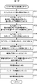
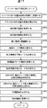
次に、図12のフローチャートを参照して、図11のステップS104において実行されるインター動き予測処理の流れの例を説明する。
[Flow of inter motion prediction processing]
Next, an example of the flow of inter motion prediction processing executed in step S104 of FIG. 11 will be described with reference to the flowchart of FIG.
ステップS131において、重み係数決定部161は、当該スライスに対する重み係数を決定する。ステップS132において、動き探索部151は、各インター予測モードで、重み無しで動き探索を行い、重み無しのモードの予測画像を生成する。ステップS133において、重み付け動き補償部162は、各インター予測モードで、ステップS131において算出された重み係数を用いて動き補償を行い、重み有りの各重みモードの予測画像を生成する。
In step S131, the weight
ステップS134において、重み付け動き補償部162は、各インター予測モードで、各重みモードの差分画像を生成する。ステップS135において、重みモード判定部122は、ステップS134において生成された各重みモードの差分画像を用いて、各インター予測モードで最適な重みモードを判定する。ステップS136において、コスト関数値生成部152は、各インター予測モードで、最適な重みモードのコスト関数値を算出する。ステップS137において、モード判定部153は、ステップS136において算出されたコスト関数値に基づいて、最適なインター予測モードを判定する。ステップS138において、動き補償部154は、最適なインター予測モード、かつ、最適な重みモードで動き補償を行い、予測画像を生成する。
In step S134, the weighted motion compensation unit 162 generates a difference image for each weight mode in each inter prediction mode. In step S135, the weight
ステップS139において、動き補償部154は、ステップS138において生成された予測画像を予測画像選択部116に出力する。ステップS140において、動き補償部154は、差分動き情報、最適モード情報、最適重みモード情報、および重み係数等を含むインター予測情報を出力する。なお、最適重みモードが重み付けOFFのモードの場合や、Explicitモードの場合、重み係数の出力は省略される。
In step S139, the
ステップS141において、動き情報バッファ155は、動き補償部154から供給された当該領域の動き情報を記憶する。
In step S141, the motion information buffer 155 stores the motion information of the region supplied from the
動き情報を記憶すると動き情報バッファ155は、インター動き予測処理を終了し、処理を図11に戻す。 When the motion information is stored, the motion information buffer 155 ends the inter motion prediction process and returns the process to FIG.
以上のように各処理を行うことにより、画像符号化装置100は、重み付け予測をより小さな領域毎に制御することができ、重み付け予測の予測精度の低減を抑制し、符号化効率を向上させることができる。
By performing each process as described above, the
<2.第2の実施の形態>
[画像復号装置]
次に、以上のように符号化された符号化データの復号について説明する。図13は、図1の画像符号化装置100に対応する画像復号装置の主な構成例を示すブロック図である。
<2. Second Embodiment>
[Image decoding device]
Next, decoding of the encoded data encoded as described above will be described. FIG. 13 is a block diagram illustrating a main configuration example of an image decoding apparatus corresponding to the
図13に示される画像復号装置200は、画像符号化装置100が生成した符号化データを、その符号化方法に対応する復号方法で復号する。
The image decoding device 200 shown in FIG. 13 decodes the encoded data generated by the
図13に示されるように画像復号装置200は、蓄積バッファ201、可逆復号部202、逆量子化部203、逆直交変換部204、演算部205、ループフィルタ206、画面並べ替えバッファ207、およびD/A変換部208を有する。また、画像復号装置200は、フレームメモリ209、選択部210、イントラ予測部211、動き予測・補償部212、および選択部213を有する。
As shown in FIG. 13, the image decoding apparatus 200 includes a
蓄積バッファ201は伝送されてきた符号化データを蓄積し、所定のタイミングにおいてその符号化データを可逆復号部202に供給する。可逆復号部202は、蓄積バッファ201より供給された、図1の可逆符号化部106により符号化された情報を、可逆符号化部106の符号化方式に対応する方式で復号する。可逆復号部202は、復号して得られた差分画像の量子化された係数データを、逆量子化部203に供給する。
The
また、可逆復号部202は、最適な予測モードにイントラ予測モードが選択されたかインター予測モードが選択されたかを判定し、その最適な予測モードに関する情報を、イントラ予測部211および動き予測・補償部212の内、選択されたと判定したモードの方に供給する。つまり、例えば、画像符号化装置100において最適な予測モードとしてイントラ予測モードが選択された場合、その最適な予測モードに関する情報であるイントラ予測情報がイントラ予測部211に供給される。また、例えば、画像符号化装置100において最適な予測モードとしてインター予測モードが選択された場合、その最適な予測モードに関する情報であるインター予測情報が動き予測・補償部212に供給される。
Further, the
逆量子化部203は、可逆復号部202により復号されて得られた量子化された係数データを、図1の量子化部105の量子化方式に対応する方式で逆量子化し、得られた係数データを逆直交変換部204に供給する。逆直交変換部204は、図1の直交変換部104の直交変換方式に対応する方式で逆量子化部203から供給される係数データを逆直交変換する。逆直交変換部204は、この逆直交変換処理により、画像符号化装置100において直交変換される前の差分画像に対応する差分画像を得る。
The
逆直交変換されて得られた差分画像は、演算部205に供給される。また、演算部205には、選択部213を介して、イントラ予測部211若しくは動き予測・補償部212から予測画像が供給される。
The difference image obtained by the inverse orthogonal transform is supplied to the
演算部205は、差分画像と予測画像とを加算し、画像符号化装置100の演算部103により予測画像が減算される前の画像に対応する再構成画像を得る。演算部205は、その再構成画像をループフィルタ206に供給する。
The
ループフィルタ206は、供給された再構成画像に対して、デブロックフィルタ処理や適応ループフィルタ処理等を含むループフィルタ処理を適宜施して復号画像を生成する。例えば、ループフィルタ206は、再構成画像に対してデブロックフィルタ処理を行うことにより、ブロック歪を除去する。また、例えば、ループフィルタ206は、そのデブロックフィルタ処理結果(ブロック歪みの除去が行われた再構成画像)に対して、ウィナーフィルタ(Wiener Filter)を用いてループフィルタ処理を行うことにより画質改善を行う。
The
なお、ループフィルタ206が行うフィルタ処理の種類は任意であり、上述した以外のフィルタ処理を行ってもよい。また、ループフィルタ206が、図1の画像符号化装置100から供給されたフィルタ係数を用いてフィルタ処理を行うようにしてもよい。
Note that the type of filter processing performed by the
ループフィルタ206は、フィルタ処理結果である復号画像を画面並べ替えバッファ207およびフレームメモリ209に供給する。なお、このループフィルタ206によるフィルタ処理は省略することもできる。つまり、演算部205の出力が、フィルタ処理されずに、フレームメモリ209に格納されるようにすることもできる。例えば、イントラ予測部211は、この画像に含まれる画素の画素値を周辺画素の画素値として利用する。
The
画面並べ替えバッファ207は、供給された復号画像の並べ替えを行う。すなわち、図1の画面並べ替えバッファ102により符号化の順番のために並べ替えられたフレームの順番が、元の表示の順番に並べ替えられる。D/A変換部208は、画面並べ替えバッファ207から供給された復号画像をD/A変換し、図示せぬディスプレイに出力し、表示させる。
The
フレームメモリ209は、供給される再構成画像や復号画像を記憶する。また、フレームメモリ209は、所定のタイミングにおいて、若しくは、イントラ予測部211や動き予測・補償部212等の外部の要求に基づいて、記憶している再構成画像や復号画像をイントラ予測部211や動き予測・補償部212に供給する。
The
イントラ予測部211は、図1のイントラ予測部114と基本的に同様の処理を行う。ただし、イントラ予測部211は、符号化の際にイントラ予測により予測画像が生成された領域に対してのみ、イントラ予測を行う。
The
動き予測・補償部212は、可逆復号部202から供給されるインター予測情報に基づいてインター動き予測処理を行い、予測画像を生成する。なお、動き予測・補償部212は、可逆復号部202から供給されるインター予測情報に基づいて、符号化の際にインター予測が行われた領域に対してのみ、インター動き予測処理を行う。また、動き予測・補償部212は、可逆復号部202から供給されるインター予測情報に含まれる最適モード情報および最適重みモード情報に基づいて、予測処理単位の領域毎に、最適なインター予測モード、かつ、最適な重みモードで、インター動き予測処理を行う。
The motion prediction /
動き予測・補償部212は、予測処理単位の領域毎に、生成した予測画像を、選択部213を介して演算部205に供給する。
The motion prediction /
なお、この予測処理単位の領域は、画像符号化装置100の場合と同様であり、少なくとも、AVCの重み付け予測を行うか否かの制御単位であるスライスよりも小さい画像単位である。
Note that this prediction processing unit area is the same as in the case of the
選択部213は、イントラ予測部211から供給される予測画像、若しくは、動き予測・補償部212から供給される予測画像を演算部205に供給する。
The
[動き予測・補償部]
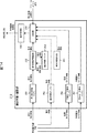
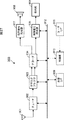
図14は、図13の動き予測・補償部212の主な構成例を示すブロック図である。
[Motion prediction / compensation unit]
FIG. 14 is a block diagram illustrating a main configuration example of the motion prediction /
図14に示されるように、動き予測・補償部212は、差分動き情報バッファ251、動き情報再構築部252、動き情報バッファ253、重み係数バッファ254、重み係数算出部255、予測モード情報バッファ256、重みモード情報バッファ257、制御部258、および動き補償部259を有する。
As illustrated in FIG. 14, the motion prediction /
差分動き情報バッファ251は、可逆復号部202から供給される、ビットストリームから抽出された差分動き情報を記憶する。差分動き情報バッファ252は、所定のタイミングにおいて、若しくは、外部からの要求に基づいて、その記憶している差分動き情報を動き情報再構築部252に供給する。
The difference motion information buffer 251 stores the difference motion information extracted from the bit stream supplied from the
動き情報再構築部252は、差分動き情報バッファ251から差分動き情報を取得すると、動き情報バッファ253から、当該領域の周辺動き情報を取得する。動き情報再構築部252は、それらの動き情報を用いて、当該領域の動き情報を再構築する。動き情報再構築部252は、再構築した動き情報を、制御部258および動き情報バッファ253に供給する。
When acquiring the differential motion information from the differential
動き情報バッファ253は、動き情報再構築部252から供給される動き情報を記憶する。動き情報バッファ253は、記憶している動き情報を、周辺動き情報として動き情報再構築部252に供給する。
The motion information buffer 253 stores the motion information supplied from the motion
重み係数バッファ254は、可逆復号部202から供給される、ビットストリームから抽出された重み係数を記憶する。重み係数バッファ254は、所定のタイミングにおいて、若しくは、外部からの要求に基づいて、その記憶している重み係数を制御部258に供給する。
The
重み係数算出部255は、重み係数を算出し、算出した重み係数を制御部258に供給する。
The weighting
予測モード情報バッファ256は、可逆復号部202から供給される、ビットストリームから抽出された最適モード情報を記憶する。予測モード情報バッファ256は、所定のタイミングにおいて、若しくは、外部からの要求に基づいて、その記憶している最適モード情報を制御部258に供給する。
The prediction mode information buffer 256 stores the optimal mode information extracted from the bit stream supplied from the
重みモード情報バッファ257は、可逆復号部202から供給される、ビットストリームから抽出された最適重みモード情報を記憶する。重みモード情報バッファ257は、所定のタイミングにおいて、若しくは、外部からの要求に基づいて、その記憶している最適重みモード情報を制御部258に供給する。
The weight mode information buffer 257 stores optimum weight mode information extracted from the bitstream supplied from the
最適なインター予測モードが、重み係数(WやD等)を伝送するExplicitモードの場合、制御部258は、重み係数バッファ254から重み係数を取得する。また、最適なインター予測モードが、重み係数(WやD等)を伝送しないInplicitモードの場合、制御部258は、重み係数算出部255に重み係数を算出させ、取得する。
When the optimal inter prediction mode is the Explicit mode that transmits a weight coefficient (W, D, etc.), the
制御部258は、予測モード情報バッファ256から最適モード情報を取得する。また、制御部258は、重みモード情報バッファ257から最適重みモード情報を取得する。さらに、制御部252は、動き情報再構築部252から動き情報を取得する。また、制御部258は、フレームメモリ209から参照画像画素値を取得する。
The
制御部258は、最適なインター予測モード、かつ、最適な重みモードでの動き補償に必要な情報を、動き補償部259に供給する。
The
動き補償部259は、制御部258から供給される各種情報を用いて、最適なインター予測モード、かつ、最適な重みモードで、当該領域の動き補償を行う。
The
以上のように、動き予測・補償部212は、画像符号化装置100から伝送される情報に基づいて、重み付け予測を制御しながら、画像符号化装置100において行われた動き予測・補償処理に応じた動き補償を行い、予測画像を生成する。
As described above, the motion prediction /
したがって、画像復号装置200は、より小さな領域毎に制御された重み付け予測により生成された動き情報を用いて動き補償を行うことができる。より具体的には、画像復号装置200は、重み付け予測を行うか否かがより小さな領域毎に制御された重み付け予測により生成された動き情報を用いて動き補償を行うことができる。 Therefore, the image decoding apparatus 200 can perform motion compensation using motion information generated by weighted prediction controlled for each smaller region. More specifically, the image decoding apparatus 200 can perform motion compensation using motion information generated by weighted prediction that is controlled for each smaller region whether or not weighted prediction is performed.
したがって、画像復号装置200は、例えば、図9に示されるような、画像全体の輝度変化が一様でない画像を符号化する場合であっても、画像全体の輝度変化のある部分についてのみ重み付け予測された動き情報を用いて、動き補償を行うことができる。これにより画像復号装置200は、画像符号化装置100による重み付け予測の予測精度の低減の抑制を実現し、符号化効率の向上を実現させることができる。
Therefore, the image decoding apparatus 200 performs weighted prediction only for a portion having a change in luminance of the entire image, even when encoding an image in which the luminance change of the entire image is not uniform as illustrated in FIG. 9, for example. Motion compensation can be performed using the motion information thus generated. Thereby, the image decoding apparatus 200 can implement | achieve suppression of the reduction of the prediction precision of the weighted prediction by the
[復号処理の流れ]
次に、以上のような画像復号装置200により実行される各処理の流れについて説明する。最初に、図15のフローチャートを参照して、復号処理の流れの例を説明する。
[Decoding process flow]
Next, the flow of each process executed by the image decoding apparatus 200 as described above will be described. First, an example of the flow of decoding processing will be described with reference to the flowchart of FIG.
復号処理が開始されると、ステップS201において、蓄積バッファ201は、伝送されてきたビットストリームを蓄積する。ステップS202において、可逆復号部202は、蓄積バッファ201から供給されるビットストリーム(符号化された差分画像情報)を復号する。
When the decoding process is started, the
このとき、イントラ予測情報やインター予測情報等、ビットストリームに含められた差分画像情報以外の各種情報も復号される。 At this time, various types of information other than the difference image information included in the bit stream such as intra prediction information and inter prediction information are also decoded.
ステップS203において、逆量子化部203は、ステップS202の処理により得られた、量子化された直交変換係数を逆量子化する。ステップS204において逆直交変換部204は、ステップS203において逆量子化された直交変換係数を逆直交変換する。
In step S203, the
ステップS205において、イントラ予測部211若しくは動き予測・補償部212は、供給された情報を用いて予測処理を行う。ステップS206において、演算部205は、ステップS204において逆直交変換されて得られた差分画像情報に、ステップS205において生成された予測画像を加算する。これにより再構成画像が生成される。
In step S205, the
ステップS207において、ループフィルタ206は、ステップS206において得られた再構成画像に対して、デブロックフィルタ処理や適応ループフィルタ処理等を含むループフィルタ処理を適宜行う。
In step S207, the
ステップS208において、画面並べ替えバッファ207は、ステップS207においてフィルタ処理されて生成された復号画像の並べ替えを行う。すなわち画像符号化装置100の画面並べ替えバッファ102により符号化のために並べ替えられたフレームの順序が、元の表示の順序に並べ替えられる。
In step S208, the
ステップS209において、D/A変換部208は、フレームの順序が並べ替えられた復号画像をD/A変換する。この復号画像が図示せぬディスプレイに出力され、表示される。
In step S209, the D /
ステップS210において、フレームメモリ209は、ステップS207においてフィルタ処理されて得られた復号画像を記憶する。この復号画像は、インター予測処理において参照画像として利用される。
In step S210, the
ステップS210の処理が終了すると、復号処理が終了される。 When the process of step S210 ends, the decoding process ends.
[予測処理の流れ]
次に、図16のフローチャートを参照して、図15のステップS205において実行される予測処理の流れの例を説明する。
[Prediction process flow]
Next, an example of the flow of prediction processing executed in step S205 in FIG. 15 will be described with reference to the flowchart in FIG.
予測処理が開始されると、イントラ予測部211は、ステップS231において、可逆復号部202から供給されるイントラ予測情報若しくはインター予測情報に基づいて、処理対象の領域が符号化の際にイントラ予測が行われたか否かを判定する。イントラ予測が行われたと判定された場合、イントラ予測部211は、処理をステップS232に進める。
When the prediction process is started, the
この場合、イントラ予測部211は、ステップS232において、イントラ予測モード情報を取得し、ステップS233において、イントラ予測によって予測画像を生成する。予測画像が生成されると、イントラ予測部211は、予測処理を終了し、処理を図15に戻す。
In this case, the
また、ステップS231において、当該領域がインター予測の行われた領域であると判定した場合、処理をステップS234に進める。ステップS234において、動き予測・補償部212は、インター動き予測処理を行う。インター動き予測処理が終了すると、動き予測・補償部212は、予測処理を終了し、処理を図15に戻す。
If it is determined in step S231 that the region is an inter-predicted region, the process proceeds to step S234. In step S234, the motion prediction /
[インター動き予測処理の流れ]
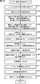
次に、図17のフローチャートを参照して、図16のステップS234において実行されるインター動き予測処理の流れの例を説明する。
[Flow of inter motion prediction processing]
Next, an example of the flow of inter motion prediction processing executed in step S234 in FIG. 16 will be described with reference to the flowchart in FIG.
インター動き予測処理が開始されると、ステップS251において、重み係数バッファ254は、Explicitモードのために、当該スライスに対する重み係数を取得し、記憶する。ステップS252において、重み係数算出部255は、Inplicitモードのために、当該スライスに対する重み係数を算出する。
When the inter motion prediction process is started, in step S251, the
ステップS253において、差分動き情報バッファ251は、可逆復号部202においてビットストリームから抽出された差分動き情報を取得する。動き情報再構築部252は、この差分動き情報を、差分動き情報バッファ251から取得する。ステップS254において、動き情報再構築部252は、動き情報バッファ253が保持している周辺動き情報を取得する。
In step S253, the differential
ステップS255において、動き情報再構築部252は、ステップS253において取得された当該領域の差分動き情報、並びに、ステップS254において取得された周辺動き情報を用いて、当該領域の動き情報を再構築する。ステップS256において、予測モード情報バッファ256は、可逆復号部202によりビットストリームから抽出された最適モード情報を取得する。制御部258は、その最適モード情報を、予測モード情報バッファ256から取得する。ステップS257において、制御部258は、その最適モード情報を用いて、動き補償のモードを決定する。
In step S255, the motion
ステップS258において、重みモード情報バッファ257は、可逆復号部202によりビットストリームから抽出された最適重みモード情報を取得する。制御部258は、その最適重みオード情報を、重みモード情報バッファ257から取得する。ステップS259において、制御部258は、その最適モード情報を用いて、動き補償の重みモードを決定する。
In step S258, the weight
ステップS260において、制御部258は、ステップS257において決定された最適な予測モード、かつ、ステップS259において決定された重みモードの動き補償に必要な情報を取得する。ステップS261において、動き補償部259は、ステップS260において取得された情報を用いて、ステップS257において決定された最適な予測モード、かつ、ステップS259において決定された重みモードで動き補償を行い、予測画像を生成する。
In step S260, the
ステップS262において、動き補償部259は、ステップS261において生成された予測画像を演算部205に供給する。ステップS263において、動き情報バッファ253は、ステップS255において再構築された動き情報を記憶する。
In step S262, the
ステップS263の処理を終了すると、動き情報バッファ253は、インター動き予測処理を終了し、処理を図16に戻す。 When the process of step S263 ends, the motion information buffer 253 ends the inter motion prediction process and returns the process to FIG.
以上のように、各処理を行うことにより、動き予測・補償部212は、画像符号化装置100から伝送される情報に基づいて、画像符号化装置100において行われた動き予測・補償処理に応じた動き補償を行い、予測画像を生成する。つまり、動き予測・補償部212は、画像符号化装置100から伝送される情報に基づいて、重み付け予測を制御しながら、画像符号化装置100において行われた動き予測・補償処理に応じた動き補償を行い、予測画像を生成する。したがって、画像復号装置200は、画像符号化装置100による重み付け予測の予測精度の低減の抑制を実現し、符号化効率の向上を実現させることができる。
As described above, by performing each process, the motion prediction /
[その他の例]
なお、以上においては、重みモードをより小さな領域毎に制御するように説明したが、この重みモードの制御単位は、スライスより小さな領域であればどのような大きさであってもよい。例えば、LCU、CU、またはPU等であってもよいし、マクロブロックやサブマクロブロックであってもよい。
[Other examples]
In the above description, the weight mode is controlled for each smaller area. However, the control unit of the weight mode may be any size as long as the area is smaller than the slice. For example, it may be an LCU, CU, PU, or the like, or may be a macro block or a sub macro block.
また、そのような領域毎に、重みモードが制御されるとともに、重み係数の値も制御されるようにしてもよい。ただし、その場合、重み係数を伝送しなければならず、その分、符号化効率が低減する恐れがある。上述したように重みモード情報によって重みモードを制御する方法の方が、重み付け予測の制御処理も容易に行うことができる。 In addition, the weighting mode may be controlled and the value of the weighting coefficient may be controlled for each region. However, in that case, the weighting coefficient must be transmitted, and the coding efficiency may be reduced accordingly. As described above, the method of controlling the weight mode based on the weight mode information can also easily perform the weighted prediction control process.
なお、以上においては、重みモードの制御として、重み付け予測のON・OFFについて説明したが、これに限らない。例えば、重み係数(WやD等)を伝送するExplicitモードで重み付け予測を行うか、重み係数(WやD等)を伝送しないInplicitモードで重み付け予測を行うかを制御するようにしてもよい。 In the above, ON / OFF of weighted prediction has been described as control of the weight mode. However, the present invention is not limited to this. For example, it may be controlled whether weighted prediction is performed in an explicit mode that transmits a weighting coefficient (W, D, etc.) or weighted prediction is performed in an Inplicit mode that does not transmit a weighting coefficient (W, D, etc.).
また、重みモードの制御において、最適重みモードの候補は3つ以上であってもよい。例えば、重み付け予測を行わない(OFF)モード、重み付け予測をExplicitモードで行うモード、および、重み付け予測をInplicitモードで行うモードの3つの重みモードを最適重みモードの候補とするようにしてもよい。 In the weight mode control, the optimum weight mode candidates may be three or more. For example, three weight modes, a mode in which weighted prediction is not performed (OFF), a mode in which weighted prediction is performed in Explicit mode, and a mode in which weighted prediction is performed in Inplicit mode may be set as candidates for the optimal weight mode.
また、重みモードの制御において、重み係数の値を選択することができるようにしてもよい。例えば、最適重みモードの各候補の重み係数が互いに異なるようにし、最適重みモードを選択することにより、重み係数が選択されるようにしてもよい。例えば、重み係数w0の重みモード、重み係数w1の重みモード、および、重み係数w2の重みモードを候補とし、それらのいずれかを最適重みモードとして選択するようにしてもよい。 Further, in the weight mode control, the value of the weight coefficient may be selected. For example, the weighting factors may be selected by making the weighting factors of the candidates for the optimum weighting mode different from each other and selecting the optimum weighting mode. For example, the weighting mode of the weighting factor w0, the weighting mode of the weighting factor w1, and the weighting mode of the weighting factor w2 may be selected as candidates, and any of them may be selected as the optimum weighting mode.
また、以上のような重みモードの制御は、図9に示されるような画像だけでなく、輝度変化が画像全体で一様でない画像に対しても有効である。例えば、画像全体が自然画像であっても、部分的に輝度変化が生じたり、部分毎に輝度変化の程度が異なる場合もある。そのような画像においても、画像全体に一様な重み係数で重み付け予測を行うと、どの部分に対しても最適でない重み係数が生成される恐れがあり、そのような重み係数で重み付け予測を行うと、予測精度が低減し、符号化効率が低減する恐れがある。 Further, the weight mode control as described above is effective not only for an image as shown in FIG. 9 but also for an image whose luminance change is not uniform across the entire image. For example, even if the entire image is a natural image, there may be a case where a luminance change occurs partially or the luminance change level varies from part to part. Even in such an image, if weighted prediction is performed with a uniform weighting factor over the entire image, a non-optimal weighting factor may be generated for any part, and weighted prediction is performed with such a weighting factor. As a result, the prediction accuracy may be reduced, and the coding efficiency may be reduced.
そこで、例えば、上述したように重みモードを制御することにより、画像符号化装置100は、各部分に対して最適な重み付け予測を行うことができる。
Therefore, for example, by controlling the weighting mode as described above, the
さらに、上述した各重みモードを候補として組み合わせるようにしてもよいし、上述した以外の重みモードを候補とするようにしてもよい。 Furthermore, the above-described weight modes may be combined as candidates, or weight modes other than those described above may be used as candidates.
さらに、インター予測モードの候補と重みモードの候補を、選択肢としてマージさせるようにしてもよい。例えば、モード0を、領域サイズ16×16のインター予測モード、重み係数w0の重みモードとし、モード1を、領域サイズ16×16のインター予測モード、重み係数w1の重みモードとし、モード2を、領域サイズ16×16のインター予測モード、重み係数w2の重みモードとし、モード3を、領域サイズ8×8のインター予測モード、重み係数w0の重みモード等とするようにしてもよい。このように、インター予測モードと重みモードを1組のモードで表すことにより、符号化効率を向上させることができる。
Further, the inter prediction mode candidate and the weight mode candidate may be merged as options. For example,
なお、上述したように、最適モード情報や最適重みモード情報を含むインター予測情報は、可逆符号化部106に供給され、CABACやCAVLC等によって符号化され、ビットストリームに付加される。このようにCABACにより符号化することにより、変化点のみがビットストリームに含められることになる。一般的な画像において、小さな領域毎に輝度変化が異なるようなケースは少ない。図9の例の場合も、画像の左右端付近の領域で輝度変化が生じないのみで、中央部の輝度変化は一様である。仮に一様でなくても、距離が近くなるほど、輝度変化の相関性は高くなる可能性が高い。したがって、ピクチャ内において最適重みモードの変化は、予測処理単位の領域の数に比べて多くはない。そこで、この最適重みモード情報をCABACのような符号化方式で符号化することにより、画像符号化装置100は、符号化効率を向上させることができる。
As described above, the inter prediction information including the optimal mode information and the optimal weight mode information is supplied to the
なお、最適重みモード情報を、変化点のみ符号化するようにしてもよい。つまり、最適重みモードが、1つ前にインター予測される領域から変化する場合のみ、変化後の重みモードを示す最適重みモード情報が符号化され、復号側に伝送されるようにしてもよい。つまり、この場合、インター予測された領域において、重みモード情報が取得できない場合、画像復号装置200は、その領域の重みモードを、1つ前に処理されたインター予測の領域と同一として処理する。 In addition, you may make it encode optimal weight mode information only in a change point. That is, only when the optimum weight mode changes from the area inter-predicted immediately before, the optimum weight mode information indicating the changed weight mode may be encoded and transmitted to the decoding side. That is, in this case, when the weight mode information cannot be acquired in the inter-predicted region, the image decoding apparatus 200 processes the weight mode of the region as the same as the inter prediction region processed immediately before.
<3.第3の実施の形態>
[画像符号化装置]
なお、予測処理対象の領域が小さい場合、どのような重み付け予測の予測精度が多少低減しても、画像全体に与える影響は小さい。したがって、重みモードの制御処理の負荷軽減の為に、重みモードを制御する領域のサイズに下限を設けるようにしてもよい。
<3. Third Embodiment>
[Image encoding device]
When the prediction processing target area is small, the influence on the entire image is small even if the prediction accuracy of any weighted prediction is somewhat reduced. Therefore, in order to reduce the load of the weight mode control processing, a lower limit may be provided for the size of the area for controlling the weight mode.
例えば、ある大きさ以上のCoding Unitに対してのみ、最適重みモード情報の伝送を行うようにしても良い。この場合、どの大きさ以上のCoding Unitに対して最適重みモード情報の伝送を行うかに関する情報を、ピクチャパラメータセットや、スライスヘッダにおいて復号側に伝送するようにしても良い。 For example, optimal weight mode information may be transmitted only to Coding Units having a certain size or larger. In this case, information regarding which size or larger Coding Unit is to be transmitted with the optimum weight mode information may be transmitted to the decoding side in a picture parameter set or a slice header.
より大きな領域を最適重みモード情報伝送の下限とする場合、最適重みモード情報の伝送による符号量増大のオーバーヘッドを抑制することができる。これに対して、より小さな領域を最適重みモード情報伝送の下限とする場合、予測効率をより向上させることができる。 When a larger area is used as the lower limit of the optimum weight mode information transmission, it is possible to suppress the overhead of increasing the code amount due to the transmission of the optimum weight mode information. On the other hand, when the smaller area is set as the lower limit of the optimum weight mode information transmission, the prediction efficiency can be further improved.
なお、最適重みモード情報が伝送されない小さな領域に対して、重み付けONのモードで動き予測・補償が行われるようにしてもよいし、重み付けOFFのモードで動き予測・補償が行われるようにしてもよい。 Note that motion prediction / compensation may be performed in the weighted ON mode or motion prediction / compensation may be performed in the weighted OFF mode for a small area where the optimal weight mode information is not transmitted. Good.
図18は、その場合の画像符号化装置100の一部の構成例を示すブロック図である。図18に示されるように、この場合の画像符号化装置100は、図1の場合の重み付け予測部121の代わりに重み付け予測部321を有し、さらに、領域サイズ制限部323を有する。
FIG. 18 is a block diagram illustrating a configuration example of a part of the
領域サイズ制限部323は、重み付け予測部321の重み係数決定部361と重み付け動き補償部362に対して、重み付け予測の制御を行う領域のサイズの下限を示す制御情報を供給する。また、領域サイズ制限部323は、その領域サイズを示す領域サイズ制限情報を可逆符号化部106に供給し、符号化させ、ビットストリームに含めて復号側に伝送させる。
The region
重み付け予測部321は、重み係数決定部361と重み付け動き補償部362を有する。
The
重み係数決定部361は、当該スライスに対する重み係数を決定し、その重み係数を、入力画像や参照画像とともに、重み付け動き補償部362に供給する。重み付け動き補償部362は、領域サイズ制限部323から供給される制限情報において指定される領域サイズより大きな領域に対してのみ、第1の実施の形態において上述したように、重み付けONの動き補償や、差分画像の算出や、最適重みモード情報のコスト関数値生成部152への供給等を行う。
The weighting
制限情報において指定される領域サイズ以下の領域に対して重み付けOFFのモードで動き予測・補償を行う場合、重み付け動き補償部362は、その領域サイズ以下の領域について、重み付けOFFの差分画像画素値を、コスト関数値生成部152に供給する。
When motion prediction / compensation is performed in a weighting-off mode for an area that is equal to or smaller than the area size specified in the restriction information, the weighting motion compensation unit 362 uses a weighted OFF difference image pixel value for an area that is smaller than the area size. And supplied to the cost function
また、制限情報において指定される領域サイズ以下の領域に対して重み付けONのモードで動き予測・補償を行う場合、重み付け動き補償部362は、その領域サイズ以下の領域について、重み付けONの差分画像画素値と重み係数を、コスト関数値生成部152に供給する。
In addition, when performing motion prediction / compensation in a weighted-on mode for an area that is equal to or smaller than the area size specified in the restriction information, the weighted motion compensation unit 362 performs a weighted-on difference image pixel for an area that is smaller than the area size. The value and the weight coefficient are supplied to the cost function
このようにすることにより、画像符号化装置100は、重み付け予測の制御処理の負荷を任意に低減させることができる。
In this way, the
[インター動き予測処理の流れ]
図19のフローチャートを参照して、その場合のインター動き予測処理の流れの例を説明する。この場合も、図12を参照して説明した第1の実施の形態の場合と基本的に同様に各処理が行われる。
[Flow of inter motion prediction processing]
With reference to the flowchart of FIG. 19, the example of the flow of the inter motion prediction process in that case is demonstrated. Also in this case, each process is performed basically in the same manner as in the case of the first embodiment described with reference to FIG.
ただし、この場合、ステップS302において、領域サイズ制限部323が、領域サイズの制限を設定する。また、ステップS304乃至ステップS306の各処理を、領域サイズ制限内の各インター予測モードで行う。
However, in this case, in step S302, the region
そして、ステップS313において、領域サイズ制限部323は、領域サイズ制限情報を可逆符号化部106に供給して符号化させ、ビットストリームに含めて復号側に伝送させる。
In step S313, the region
ステップS301は、ステップS131と同様に実行される。ステップS303は、ステップS132と同様に実行される。ステップS307乃至ステップS312の各処理は、ステップS136乃至ステップS141の各処理と同様に実行される。 Step S301 is executed in the same manner as step S131. Step S303 is executed in the same manner as step S132. The processes in steps S307 to S312 are executed in the same manner as the processes in steps S136 to S141.
ステップS313の処理が終了すると領域サイズ制限部323は、処理を図11に戻す。
When the process of step S313 ends, the region
なお、以上は、制限情報において指定される領域サイズ以下の領域に対して重み付けOFFのモードで動き予測・補償を行う場合の処理の流れを説明したものである。制限情報において指定される領域サイズ以下の領域に対して重み付けONのモードで動き予測・補償を行う場合、ステップS303の処理を領域サイズ制限内の各インター予測モードで行うようにし、ステップS304の処理を全てのインター予測モードで行うようにすればよい。 The above describes the flow of processing when motion prediction / compensation is performed in a weighting-off mode for an area that is smaller than the area size specified in the restriction information. When motion prediction / compensation is performed in the weighted ON mode for an area smaller than the area size specified in the restriction information, the process in step S303 is performed in each inter prediction mode within the area size restriction, and the process in step S304 is performed. May be performed in all inter prediction modes.
以上のように処理を行うことにより、画像符号化装置100は、重み付け予測の制御処理の負荷を任意に低減させることができる。
By performing the processing as described above, the
<4.第4の実施の形態>
[画像復号装置]
次に、第3の実施の形態の画像符号化装置100に対応する画像復号装置について説明する。図20は、その場合の画像復号装置200が有する動き予測・補償部の主な構成例を示すブロック図である。
<4. Fourth Embodiment>
[Image decoding device]
Next, an image decoding apparatus corresponding to the
図20に示されるように、この場合の画像復号装置200は、動き予測・補償部212の代わりに、動き予測・補償部412を有する。
As illustrated in FIG. 20, the image decoding apparatus 200 in this case includes a motion prediction /
動き予測・補償部412は、図20に示されるように、基本的に動き予測・補償部212と同様の構成を有するが、さらに領域サイズ制限情報バッファ451を有する。また、動き予測・補償部412は、制御部258の代わりに制御部458を有する。この領域サイズ制限情報バッファ451は、可逆復号部202においてビットストリームから抽出された領域サイズ制限情報、すなわち、画像符号化装置100から伝送された、第3の実施の形態において説明した領域サイズ制限情報を取得し、記憶する。領域サイズ制限情報バッファ451は、その領域サイズ制限情報を、所定のタイミング、若しくは、外部からの要求に基づいて制御部458に供給する。
As shown in FIG. 20, the motion prediction /
制御部458は、その領域サイズ制限情報に従って、最適重みモード情報を解析し、重みモードを判定する。すなわち、制御部458は、領域サイズ制限情報に指定される領域サイズより大きな領域についてのみ、最適重みモード情報を参照して重みモードを決定し、領域サイズ制限情報に指定される領域サイズ以下の小さな領域については、最適重みモード情報を参照せずに、所定の重みモードに設定する。
The
このようにすることにより、動き補償部259は、動き補償部154と同様に動き補償を行うことができる。これにより、画像復号装置200は、重み付け予測の制御処理の負荷を低減させることができる。
By doing so, the
[インター動き予測処理の流れ]
図21のフローチャートを参照して、その場合のインター動き予測処理の流れの例を説明する。この場合も、図17を参照して説明した第2の実施の形態の場合と基本的に同様に各処理が行われる。
[Flow of inter motion prediction processing]
An example of the flow of inter motion prediction processing in that case will be described with reference to the flowchart of FIG. Also in this case, each process is performed basically in the same manner as in the case of the second embodiment described with reference to FIG.
ただし、この場合、ステップS401において、領域サイズ制限情報バッファ451が、領域サイズ制限情報を取得し、記憶する。制御部259は、領域サイズ制限情報バッファ451から、その領域サイズ制限情報を取得する。
In this case, however, the region size restriction information buffer 451 acquires and stores the region size restriction information in step S401. The
ステップS402乃至ステップS408の各処理は、ステップS251乃至ステップS257の各処理と同様に実行される。 Each process of step S402 thru | or step S408 is performed similarly to each process of step S251 thru | or step S257.
ステップS409において、制御部458は、処理対象の領域のサイズが領域サイズ制限内であるか否かを判定し、制限内であると判定された場合、処理をステップS410に進める。ステップS410およびステップS411の各処理は、ステップS258およびステップS259と同様に実行される。ステップS411の処理が終了すると、制御部458は、処理をステップS413に進める。
In step S409, the
また、ステップS409において、処理対象の領域のサイズが領域サイズ制限内でないと判定された場合、制御部458は、処理をステップS412に進め、動き補償のおみモードを重み予測無しのモードに決定する。ステップS412の処理が終了すると、制御部458は、処理をステップS413に進める。
If it is determined in step S409 that the size of the region to be processed is not within the region size limit, the
ステップS413乃至ステップS416の各処理は、ステップS260乃至ステップS263の各処理と同様に実行される。 Each process of step S413 thru | or step S416 is performed similarly to each process of step S260 thru | or step S263.
ステップS416の処理が終了すると動き情報バッファ253は、処理を図16に戻す。 When the process of step S416 ends, the motion information buffer 253 returns the process to FIG.
なお、以上は、制限情報において指定される領域サイズ以下の領域に対して重み付けOFFのモードで動き予測・補償を行う場合の処理の流れを説明したものである。制限情報において指定される領域サイズ以下の領域に対して重み付けONのモードで動き予測・補償を行う場合、ステップS412において、制御部458が、動き補償の重みモードを重み予測有りのモードに決定すればよい。
The above describes the flow of processing when motion prediction / compensation is performed in a weighting-off mode for an area that is smaller than the area size specified in the restriction information. When motion prediction / compensation is performed in the weighted ON mode for an area that is equal to or smaller than the area size specified in the restriction information, in step S412, the
以上のように処理を行うことにより、画像復号装置200は、重み付け予測の制御処理の負荷を低減させることができる。 By performing the process as described above, the image decoding apparatus 200 can reduce the load of the weighted prediction control process.
<5.第5の実施の形態>
[画像符号化装置]
なお、以上において、動き予測・補償処理の手順について一例を示したが、上述した以外の手順であってもよい。
<5. Fifth embodiment>
[Image encoding device]
In the above, an example of the procedure of motion prediction / compensation processing has been described, but a procedure other than the above may be used.
例えば、全てのインター予測モードについて、全ての重みモードでコスト関数値を生成し、その中から最適なインター予測モードと重みモードの組み合わせを求めるようにしてもよい。 For example, for all inter prediction modes, cost function values may be generated in all weight modes, and an optimal combination of the inter prediction mode and the weight mode may be obtained therefrom.
図22は、その場合の画像符号化装置100の一部の構成例を示すブロック図である。図22に示されるように、この場合の画像符号化装置100は、動き予測・補償部115の代わりに動き予測・補償部515を有する。また、この場合の画像符号化装置100は、重み付け予測部121の代わりに重み付け予測部521を有する。なお、重みモード判定部122は省略される。
FIG. 22 is a block diagram illustrating a configuration example of a part of the
動き予測・補償部515は、動き予測・補償部115と基本的に同様の構成を有するが、コスト関数値生成部152の代わりにコスト関数値生成部552を有し、モード判定部153の代わりにモード判定部553を有する。
The motion prediction /
重み付け予測部521は、重み付け予測部121と基本的に同様の構成を有するが、重み付け動き補償部162の代わりに、重み付け動き補償部562を有する。
The weighted prediction unit 521 has basically the same configuration as the
重み付け動き補償部562は、全てのインター予測モードについて、全ての重みモードで差分画像を生成する。重み付け動き補償部562は、全てのインター予測モード、かつ、全ての重みモードについて、差分画像画素値を、重み係数とともにコスト関数値生成部552に供給する。
The weighted
コスト関数値生成部552は、全てのインター予測モード、かつ、全ての重みモードについて、差分画像画素値を用いてコスト関数値を算出する。また、コスト関数値生成部552は、全てのインター予測モード、かつ、全ての重みモードについて、コスト関数値生成部152の場合と同様に、周辺動き情報と当該領域の動き情報との差分動き情報を生成する。
The cost function value generation unit 552 calculates cost function values using the difference image pixel values for all inter prediction modes and all weight modes. Further, the cost function value generation unit 552, for all inter prediction modes and all weight modes, as in the case of the cost function
コスト関数値生成部552は、全てのインター予測モード、かつ、全ての重みモードについて、差分動き情報およびコスト関数値を、重み係数とともにモード判定部553に供給する。
The cost function value generation unit 552 supplies the difference motion information and the cost function value to the
モード判定部553は、供給された全てのインター予測モード、かつ、全ての重みモードのコスト関数値を用いて、最適なインター予測モードと、最適な重みモードを決定する。
The
それ以外の処理は、動き予測・補償部115の場合と同様である。
Other processes are the same as those in the motion prediction /
このようにすることにより、画像符号化装置100は、最適なインター予測モードおよび最適な重みモードをより正確に求めることができ、符号化効率をより向上させることができる。
By doing in this way, the
[インター動き予測処理の流れ]
この場合のインター動き予測処理の流れの例を図23のフローチャートを参照して説明する。
[Flow of inter motion prediction processing]
An example of the flow of inter motion prediction processing in this case will be described with reference to the flowchart of FIG.
この場合も、インター動き予測処理は、基本的に図12のフローチャートを参照して説明した第1の実施の形態の場合と同様に実行される。 Also in this case, the inter motion prediction process is basically executed in the same manner as in the case of the first embodiment described with reference to the flowchart of FIG.
つまり、ステップS501乃至ステップS504の各処理は、ステップS131乃至ステップS134の各処理と同様に実行される。ただし、ステップS135の処理は省略される。 That is, each process of step S501 to step S504 is executed in the same manner as each process of step S131 to step S134. However, the process of step S135 is omitted.
ステップS505において、コスト関数生成部552は、各インター予測モードで、各重みモードのコスト関数値を算出する。ステップS506において、モード判定部503は、最適な重みモードおよび最適なインター予測モードを判定する。
In step S505, the cost function generation unit 552 calculates a cost function value for each weight mode in each inter prediction mode. In step S506, the
ステップS507乃至ステップS510の各処理は、図12のステップS138乃至ステップS141の各処理と同様に実行される。 Steps S507 to S510 are executed in the same manner as steps S138 to S141 in FIG.
以上のように処理を行うことにより、画像符号化装置100は、最適なインター予測モードおよび最適な重みモードをより正確に求めることができ、符号化効率をより向上させることができる。
By performing the processing as described above, the
<6.第6の実施の形態>
[画像符号化装置]
また、例えば、所定の重みモードで最適なインター予測モードが判定された後、そのインター予測モードについて最適な重みモードが決定されるようにしてもよい。
<6. Sixth Embodiment>
[Image encoding device]
Further, for example, after an optimal inter prediction mode is determined in a predetermined weight mode, an optimal weight mode may be determined for the inter prediction mode.
図24は、その場合の画像符号化装置100の一部の構成例を示すブロック図である。図24に示されるように、この場合の画像符号化装置100は、動き予測・補償部115の代わりに動き予測・補償部615を有する。また、この場合の画像符号化装置100は、重み付け予測部121の代わりに重み付け予測部621を有する。さらに、この場合の画像符号化装置100は、重みモード判定部122の代わりに、重みモード判定部622を有する。
FIG. 24 is a block diagram illustrating a configuration example of a part of the
動き予測・補償部615は、動き予測・補償部115と基本的に同様の構成を有するが、動き探索部151の代わりに動き探索部651を有し、コスト関数値生成部152の代わりにコスト関数値生成部652を有し、モード判定部153の代わりにモード判定部653を有する。
The motion prediction /
重み付け予測部621は、重み付け予測部121と基本的に同様の構成を有するが、重み付け動き補償部162の代わりに、重み付け動き補償部662を有し、さらに、コスト関数値生成部663を有する。
The weighted prediction unit 621 has basically the same configuration as the
動き探索部651は、全てのインター予測モードについて、重み付けOFFの動き探索を行い、重み付けOFFの差分画像画素値と動き情報をコスト関数値652に供給する。
The
コスト関数値生成部652は、全てのインター予測モードについて、重み付けOFFの重みモードのコスト関数値を算出するとともに、周辺動き情報と当該領域の動き情報の差分動き情報を生成し、差分動き情報とともにモード判定部653に供給する。
The cost function
モード判定部653は、そのコスト関数値に基づいて最適なインター予測モードを判定し、最適モード情報を重み付け予測部621の重み付け動き補償部662に供給する。また、モード判定部653は、最適モード情報を重みモード判定部622に供給する。モード判定部653は、また、最適なインター予測モードについて、差分動き情報と、重み付けOFFの重みモードのコスト関数値も重みモード判定部622に供給する。
The
重み付け予測部621の重み付け動き補償部662は、最適なインター予測モードについて、重み付けONのモードで動き補償を行い、予測画像と入力画像の差分画像を生成する。重み付け動き補償部662は、最適なインター予測モードの重み付けONのモードの差分画像画素値と重み係数とをコスト関数値生成部663に供給する。
The weighted motion compensation unit 662 of the weighted prediction unit 621 performs motion compensation in the weighted ON mode for the optimal inter prediction mode, and generates a difference image between the predicted image and the input image. The weighted motion compensation unit 662 supplies the cost function
コスト関数値生成部663は、その差分画像画素値についてコスト関数値を生成し、重み係数とともに重みモード判定部622に供給する。
The cost function
重みモード判定部622は、モード判定部653とコスト関数値生成部663から供給された各コスト関数値を比較し、最適な重みモードを決定する。
The weight
重みモード判定部663は、差分動き情報、最適モード情報、最適重みモード情報、および重み係数を動き補償部154に供給する。
The weight
それ以外の処理は、動き予測・補償部115の場合と同様である。
Other processes are the same as those in the motion prediction /
このようにすることにより、画像符号化装置100は、最適なモードを選択するための処理をより容易に行うことができ、負荷を低減させることができる。
By doing in this way, the
[インター動き予測処理の流れ]
この場合のインター動き予測処理の流れの例を図25のフローチャートを参照して説明する。
[Flow of inter motion prediction processing]
An example of the flow of inter motion prediction processing in this case will be described with reference to the flowchart of FIG.
この場合も、インター動き予測処理は、基本的に図12のフローチャートを参照して説明した第1の実施の形態の場合と同様に実行される。 Also in this case, the inter motion prediction process is basically executed in the same manner as in the case of the first embodiment described with reference to the flowchart of FIG.
つまり、ステップS601およびステップS602の各処理は、ステップS131およびステップS132の各処理と同様に実行される。 That is, each process of step S601 and step S602 is performed similarly to each process of step S131 and step S132.
ステップS603において、動き探索部651は、全てのインター予測モードで重み無しのモードの差分画像を生成する。ステップS604において、コスト関数値生成部652は、全てのインター予測モードで重み無しのモードのコスト関数値を算出する。
In step S <b> 603, the
ステップS605において、モード判定部653は、重み無しのモードで、最適なインター予測モードを判定する。
In step S605, the
ステップS606において、重み付け動き補償部662は、最適なインター予測モードで重み係数を用いて動き補償を行い、重み有りのモードの予測画像を生成する。ステップS607において、重み付け動き補償部662は、最適なインター予測モードで重み有りのモードの差分画像を生成する。ステップS608において、コスト関数値生成部663は、最適なインター予測モードでコスト関数値を算出する。ステップS609において、重みモード判定部622は、最適なインター予測モードで最適な重みモードを判定する。
In step S606, the weighted motion compensation unit 662 performs motion compensation using a weighting coefficient in the optimal inter prediction mode, and generates a prediction image in a weighted mode. In step S607, the weighted motion compensation unit 662 generates a weighted mode difference image in the optimal inter prediction mode. In step S608, the cost function
ステップS610乃至ステップS613の各処理は、ステップS138乃至ステップS141の各処理と同様に実行される。 Each process of step S610 to step S613 is executed in the same manner as each process of step S138 to step S141.
以上のように処理を行うことにより、符号化装置100は、最適なモードを選択するための処理をより容易に行うことができ、負荷を低減させることができる。
By performing the processing as described above, the
なお、本技術は、例えば、MPEG、H.26x等の様に、離散コサイン変換等の直交変換と動き補償によって圧縮された画像情報(ビットストリーム)を、衛星放送、ケーブルテレビジョン、インターネット、または携帯電話機などのネットワークメディアを介して受信する際に用いられる画像符号化装置および画像復号装置に適用することができる。また、本技術は、光、磁気ディスク、およびフラッシュメモリのような記憶メディア上で処理する際に用いられる画像符号化装置および画像復号装置に適用することができる。さらに、本技術は、それらの画像符号化装置および画像復号装置などに含まれるイントラ予測装置にも適用することができる。 Note that the present technology is, for example, MPEG, H.264, and the like. When receiving image information (bitstream) compressed by orthogonal transformation such as discrete cosine transformation and motion compensation, such as 26x, via network media such as satellite broadcasting, cable television, the Internet, or mobile phones. The present invention can be applied to an image encoding device and an image decoding device used in the above. In addition, the present technology can be applied to an image encoding device and an image decoding device that are used when processing on a storage medium such as an optical, magnetic disk, and flash memory. Furthermore, the present technology can also be applied to intra prediction apparatuses included in such image encoding apparatuses and image decoding apparatuses.
<7.第7の実施の形態>
[パーソナルコンピュータ]
上述した一連の処理は、ハードウエアにより実行することもできるし、ソフトウエアにより実行することもできる。一連の処理をソフトウエアにより実行する場合には、そのソフトウエアを構成するプログラムが、コンピュータにインストールされる。ここで、コンピュータには、専用のハードウエアに組み込まれているコンピュータや、各種のプログラムをインストールすることで、各種の機能を実行することが可能な汎用のパーソナルコンピュータなどが含まれる。
<7. Seventh Embodiment>
[Personal computer]
The series of processes described above can be executed by hardware or can be executed by software. When a series of processing is executed by software, a program constituting the software is installed in the computer. Here, the computer includes a computer incorporated in dedicated hardware, a general-purpose personal computer capable of executing various functions by installing various programs, and the like.
図26において、パーソナルコンピュータ700のCPU(Central Processing Unit)701は、ROM(Read Only Memory)702に記憶されているプログラム、または記憶部713からRAM(Random Access Memory)703にロードされたプログラムに従って各種の処理を実行する。RAM703にはまた、CPU701が各種の処理を実行する上において必要なデータなども適宜記憶される。
In FIG. 26, a CPU (Central Processing Unit) 701 of the personal computer 700 performs various processes according to a program stored in a ROM (Read Only Memory) 702 or a program loaded from a
CPU701、ROM702、およびRAM703は、バス704を介して相互に接続されている。このバス704にはまた、入出力インタフェース710も接続されている。
The
入出力インタフェース710には、キーボード、マウスなどよりなる入力部711、CRT(Cathode Ray Tube)やLCD(Liquid Crystal Display)などよりなるディスプレイ、並びにスピーカなどよりなる出力部712、ハードディスクなどより構成される記憶部713、モデムなどより構成される通信部714が接続されている。通信部714は、インターネットを含むネットワークを介しての通信処理を行う。
The input /
入出力インタフェース710にはまた、必要に応じてドライブ715が接続され、磁気ディスク、光ディスク、光磁気ディスク、或いは半導体メモリなどのリムーバブルメディア721が適宜装着され、それらから読み出されたコンピュータプログラムが、必要に応じて記憶部713にインストールされる。
A
上述した一連の処理をソフトウエアにより実行させる場合には、そのソフトウエアを構成するプログラムが、ネットワークや記録媒体からインストールされる。 When the above-described series of processing is executed by software, a program constituting the software is installed from a network or a recording medium.
この記録媒体は、例えば、図26に示されるように、装置本体とは別に、ユーザにプログラムを配信するために配布される、プログラムが記録されている磁気ディスク(フレキシブルディスクを含む)、光ディスク(CD-ROM(Compact Disc - Read Only Memory),DVD(Digital Versatile Disc)を含む)、光磁気ディスク(MD(Mini Disc)を含む)、若しくは半導体メモリなどよりなるリムーバブルメディア721により構成されるだけでなく、装置本体に予め組み込まれた状態でユーザに配信される、プログラムが記録されているROM702や、記憶部713に含まれるハードディスクなどで構成される。
For example, as shown in FIG. 26, the recording medium is distributed to distribute the program to the user separately from the apparatus main body, and includes a magnetic disk (including a flexible disk) on which the program is recorded, an optical disk ( It is only composed of removable media 721 consisting of CD-ROM (compact disc-read only memory), DVD (including digital versatile disc), magneto-optical disc (including MD (mini disc)), or semiconductor memory. Rather, it is composed of a
なお、コンピュータが実行するプログラムは、本明細書で説明する順序に沿って時系列に処理が行われるプログラムであっても良いし、並列に、あるいは呼び出しが行われたとき等の必要なタイミングで処理が行われるプログラムであっても良い。 The program executed by the computer may be a program that is processed in time series in the order described in this specification, or in parallel or at a necessary timing such as when a call is made. It may be a program for processing.
また、本明細書において、記録媒体に記録されるプログラムを記述するステップは、記載された順序に沿って時系列的に行われる処理はもちろん、必ずしも時系列的に処理されなくとも、並列的あるいは個別に実行される処理をも含むものである。 Further, in the present specification, the step of describing the program recorded on the recording medium is not limited to the processing performed in chronological order according to the described order, but may be performed in parallel or It also includes processes that are executed individually.
また、本明細書において、システムとは、複数のデバイス(装置)により構成される装置全体を表すものである。 Further, in this specification, the system represents the entire apparatus composed of a plurality of devices (apparatuses).
また、以上において、1つの装置(または処理部)として説明した構成を分割し、複数の装置(または処理部)として構成するようにしてもよい。逆に、以上において複数の装置(または処理部)として説明した構成をまとめて1つの装置(または処理部)として構成されるようにしてもよい。また、各装置(または各処理部)の構成に上述した以外の構成を付加するようにしてももちろんよい。さらに、システム全体としての構成や動作が実質的に同じであれば、ある装置(または処理部)の構成の一部を他の装置(または他の処理部)の構成に含めるようにしてもよい。つまり、本技術は、上述した実施の形態に限定されるものではなく、本技術の要旨を逸脱しない範囲において種々の変更が可能である。 In addition, in the above description, the configuration described as one device (or processing unit) may be divided and configured as a plurality of devices (or processing units). Conversely, the configurations described above as a plurality of devices (or processing units) may be combined into a single device (or processing unit). Of course, a configuration other than that described above may be added to the configuration of each device (or each processing unit). Furthermore, if the configuration and operation of the entire system are substantially the same, a part of the configuration of a certain device (or processing unit) may be included in the configuration of another device (or other processing unit). . That is, the present technology is not limited to the above-described embodiment, and various modifications can be made without departing from the gist of the present technology.
上述した実施形態に係る画像符号化装置及び画像復号装置は、衛星放送、ケーブルTVなどの有線放送、インターネット上での配信、及びセルラー通信による端末への配信などにおける送信機若しくは受信機、光ディスク、磁気ディスク及びフラッシュメモリなどの媒体に画像を記録する記録装置、又は、これら記憶媒体から画像を再生する再生装置などの様々な電子機器に応用され得る。以下、4つの応用例について説明する。 An image encoding device and an image decoding device according to the above-described embodiments include a transmitter or a receiver in optical broadcasting, satellite broadcasting, cable broadcasting such as cable TV, distribution on the Internet, and distribution to terminals by cellular communication, etc. The present invention can be applied to various electronic devices such as a recording device that records an image on a medium such as a magnetic disk and a flash memory, or a playback device that reproduces an image from these storage media. Hereinafter, four application examples will be described.
<8.第8の実施の形態>
[第1の応用例:テレビジョン受像機]
図27は、上述した実施形態を適用したテレビジョン装置の概略的な構成の一例を示している。テレビジョン装置900は、アンテナ901、チューナ902、デマルチプレクサ903、デコーダ904、映像信号処理部905、表示部906、音声信号処理部907、スピーカ908、外部インタフェース909、制御部910、ユーザインタフェース911、及びバス912を備える。
<8. Eighth Embodiment>
[First application example: television receiver]
FIG. 27 illustrates an example of a schematic configuration of a television apparatus to which the above-described embodiment is applied. The
チューナ902は、アンテナ901を介して受信される放送信号から所望のチャンネルの信号を抽出し、抽出した信号を復調する。そして、チューナ902は、復調により得られた符号化ビットストリームをデマルチプレクサ903へ出力する。即ち、チューナ902は、画像が符号化されている符号化ストリームを受信する、テレビジョン装置900における伝送手段としての役割を有する。
The
デマルチプレクサ903は、符号化ビットストリームから視聴対象の番組の映像ストリーム及び音声ストリームを分離し、分離した各ストリームをデコーダ904へ出力する。また、デマルチプレクサ903は、符号化ビットストリームからEPG(Electronic Program Guide)などの補助的なデータを抽出し、抽出したデータを制御部910に供給する。なお、デマルチプレクサ903は、符号化ビットストリームがスクランブルされている場合には、デスクランブルを行ってもよい。
The
デコーダ904は、デマルチプレクサ903から入力される映像ストリーム及び音声ストリームを復号する。そして、デコーダ904は、復号処理により生成される映像データを映像信号処理部905へ出力する。また、デコーダ904は、復号処理により生成される音声データを音声信号処理部907へ出力する。
The
映像信号処理部905は、デコーダ904から入力される映像データを再生し、表示部906に映像を表示させる。また、映像信号処理部905は、ネットワークを介して供給されるアプリケーション画面を表示部906に表示させてもよい。また、映像信号処理部905は、映像データについて、設定に応じて、例えばノイズ除去などの追加的な処理を行ってもよい。さらに、映像信号処理部905は、例えばメニュー、ボタン又はカーソルなどのGUI(Graphical User Interface)の画像を生成し、生成した画像を出力画像に重畳してもよい。
The video
表示部906は、映像信号処理部905から供給される駆動信号により駆動され、表示デバイス(例えば、液晶ディスプレイ、プラズマディスプレイ又はOELD(Organic ElectroLuminescence Display)(有機ELディスプレイ)など)の映像面上に映像又は画像を表示する。
The
音声信号処理部907は、デコーダ904から入力される音声データについてD/A変換及び増幅などの再生処理を行い、スピーカ908から音声を出力させる。また、音声信号処理部907は、音声データについてノイズ除去などの追加的な処理を行ってもよい。
The audio
外部インタフェース909は、テレビジョン装置900と外部機器又はネットワークとを接続するためのインタフェースである。例えば、外部インタフェース909を介して受信される映像ストリーム又は音声ストリームが、デコーダ904により復号されてもよい。即ち、外部インタフェース909もまた、画像が符号化されている符号化ストリームを受信する、テレビジョン装置900における伝送手段としての役割を有する。
The
制御部910は、CPUなどのプロセッサ、並びにRAM及びROMなどのメモリを有する。メモリは、CPUにより実行されるプログラム、プログラムデータ、EPGデータ、及びネットワークを介して取得されるデータなどを記憶する。メモリにより記憶されるプログラムは、例えば、テレビジョン装置900の起動時にCPUにより読み込まれ、実行される。CPUは、プログラムを実行することにより、例えばユーザインタフェース911から入力される操作信号に応じて、テレビジョン装置900の動作を制御する。
The
ユーザインタフェース911は、制御部910と接続される。ユーザインタフェース911は、例えば、ユーザがテレビジョン装置900を操作するためのボタン及びスイッチ、並びに遠隔制御信号の受信部などを有する。ユーザインタフェース911は、これら構成要素を介してユーザによる操作を検出して操作信号を生成し、生成した操作信号を制御部910へ出力する。
The
バス912は、チューナ902、デマルチプレクサ903、デコーダ904、映像信号処理部905、音声信号処理部907、外部インタフェース909及び制御部910を相互に接続する。
The
このように構成されたテレビジョン装置900において、デコーダ904は、上述した実施形態に係る画像復号装置の機能を有する。それにより、テレビジョン装置900での画像の復号に際して、重み付け予測の制御をより小さい単位で行うことによって予測精度を向上させることにより、符号化効率の向上を実現させることができる。
In the
<9.第9の実施の形態>
[第2の応用例:携帯電話機]
図28は、上述した実施形態を適用した携帯電話機の概略的な構成の一例を示している。携帯電話機920は、アンテナ921、通信部922、音声コーデック923、スピーカ924、マイクロホン925、カメラ部926、画像処理部927、多重分離部928、記録再生部929、表示部930、制御部931、操作部932、及びバス933を備える。
<9. Ninth Embodiment>
[Second application example: mobile phone]
FIG. 28 shows an example of a schematic configuration of a mobile phone to which the above-described embodiment is applied. A
アンテナ921は、通信部922に接続される。スピーカ924及びマイクロホン925は、音声コーデック923に接続される。操作部932は、制御部931に接続される。バス933は、通信部922、音声コーデック923、カメラ部926、画像処理部927、多重分離部928、記録再生部929、表示部930、及び制御部931を相互に接続する。
The
携帯電話機920は、音声通話モード、データ通信モード、撮影モード及びテレビ電話モードを含む様々な動作モードで、音声信号の送受信、電子メール又は画像データの送受信、画像の撮像、及びデータの記録などの動作を行う。
The
音声通話モードにおいて、マイクロホン925により生成されるアナログ音声信号は、音声コーデック923に供給される。音声コーデック923は、アナログ音声信号を音声データへ変換し、変換された音声データをA/D変換し圧縮する。そして、音声コーデック923は、圧縮後の音声データを通信部922へ出力する。通信部922は、音声データを符号化及び変調し、送信信号を生成する。そして、通信部922は、生成した送信信号を、アンテナ921を介して基地局(図示せず)へ送信する。また、通信部922は、アンテナ921を介して受信される無線信号を増幅し及び周波数変換し、受信信号を取得する。そして、通信部922は、受信信号を復調及び復号して音声データを生成し、生成した音声データを音声コーデック923へ出力する。音声コーデック923は、音声データを伸張し及びD/A変換し、アナログ音声信号を生成する。そして、音声コーデック923は、生成した音声信号をスピーカ924に供給して音声を出力させる。
In the voice call mode, an analog voice signal generated by the microphone 925 is supplied to the
また、データ通信モードにおいて、例えば、制御部931は、操作部932を介するユーザによる操作に応じて、電子メールを構成する文字データを生成する。また、制御部931は、文字を表示部930に表示させる。また、制御部931は、操作部932を介するユーザからの送信指示に応じて電子メールデータを生成し、生成した電子メールデータを通信部922へ出力する。通信部922は、電子メールデータを符号化及び変調し、送信信号を生成する。そして、通信部922は、生成した送信信号を、アンテナ921を介して基地局(図示せず)へ送信する。また、通信部922は、アンテナ921を介して受信される無線信号を増幅し及び周波数変換し、受信信号を取得する。そして、通信部922は、受信信号を復調及び復号して電子メールデータを復元し、復元した電子メールデータを制御部931へ出力する。制御部931は、表示部930に電子メールの内容を表示させると共に、電子メールデータを記録再生部929の記憶媒体に記憶させる。
Further, in the data communication mode, for example, the
記録再生部929は、読み書き可能な任意の記憶媒体を有する。例えば、記憶媒体は、RAM又はフラッシュメモリなどの内蔵型の記憶媒体であってもよく、ハードディスク、磁気ディスク、光磁気ディスク、光ディスク、USB(Unallocated Space Bitmap)メモリ、又はメモリカードなどの外部装着型の記憶媒体であってもよい。
The recording / reproducing
また、撮影モードにおいて、例えば、カメラ部926は、被写体を撮像して画像データを生成し、生成した画像データを画像処理部927へ出力する。画像処理部927は、カメラ部926から入力される画像データを符号化し、符号化ストリームを記憶再生部929の記憶媒体に記憶させる。
In the shooting mode, for example, the
また、テレビ電話モードにおいて、例えば、多重分離部928は、画像処理部927により符号化された映像ストリームと、音声コーデック923から入力される音声ストリームとを多重化し、多重化したストリームを通信部922へ出力する。通信部922は、ストリームを符号化及び変調し、送信信号を生成する。そして、通信部922は、生成した送信信号を、アンテナ921を介して基地局(図示せず)へ送信する。また、通信部922は、アンテナ921を介して受信される無線信号を増幅し及び周波数変換し、受信信号を取得する。これら送信信号及び受信信号には、符号化ビットストリームが含まれ得る。そして、通信部922は、受信信号を復調及び復号してストリームを復元し、復元したストリームを多重分離部928へ出力する。多重分離部928は、入力されるストリームから映像ストリーム及び音声ストリームを分離し、映像ストリームを画像処理部927、音声ストリームを音声コーデック923へ出力する。画像処理部927は、映像ストリームを復号し、映像データを生成する。映像データは、表示部930に供給され、表示部930により一連の画像が表示される。音声コーデック923は、音声ストリームを伸張し及びD/A変換し、アナログ音声信号を生成する。そして、音声コーデック923は、生成した音声信号をスピーカ924に供給して音声を出力させる。
Further, in the videophone mode, for example, the
このように構成された携帯電話機920において、画像処理部927は、上述した実施形態に係る画像符号化装置及び画像復号装置の機能を有する。それにより、携帯電話機920での画像の符号化及び復号に際して、重み付け予測の制御をより小さい単位で行うことによって予測精度を向上させることにより、符号化効率を向上させることができる。
In the
<10.第10の実施の形態>
[第3の応用例:記録再生装置]
図29は、上述した実施形態を適用した記録再生装置の概略的な構成の一例を示している。記録再生装置940は、例えば、受信した放送番組の音声データ及び映像データを符号化して記録媒体に記録する。また、記録再生装置940は、例えば、他の装置から取得される音声データ及び映像データを符号化して記録媒体に記録してもよい。また、記録再生装置940は、例えば、ユーザの指示に応じて、記録媒体に記録されているデータをモニタ及びスピーカ上で再生する。このとき、記録再生装置940は、音声データ及び映像データを復号する。
<10. Tenth Embodiment>
[Third application example: recording / reproducing apparatus]
FIG. 29 shows an example of a schematic configuration of a recording / reproducing apparatus to which the above-described embodiment is applied. For example, the recording / reproducing
記録再生装置940は、チューナ941、外部インタフェース942、エンコーダ943、HDD(Hard Disk Drive)944、ディスクドライブ945、セレクタ946、デコーダ947、OSD(On-Screen Display)948、制御部949、及びユーザインタフェース950を備える。
The recording / reproducing
チューナ941は、アンテナ(図示せず)を介して受信される放送信号から所望のチャンネルの信号を抽出し、抽出した信号を復調する。そして、チューナ941は、復調により得られた符号化ビットストリームをセレクタ946へ出力する。即ち、チューナ941は、記録再生装置940における伝送手段としての役割を有する。
The
外部インタフェース942は、記録再生装置940と外部機器又はネットワークとを接続するためのインタフェースである。外部インタフェース942は、例えば、IEEE1394インタフェース、ネットワークインタフェース、USBインタフェース、又はフラッシュメモリインタフェースなどであってよい。例えば、外部インタフェース942を介して受信される映像データ及び音声データは、エンコーダ943へ入力される。即ち、外部インタフェース942は、記録再生装置940における伝送手段としての役割を有する。
The
エンコーダ943は、外部インタフェース942から入力される映像データ及び音声データが符号化されていない場合に、映像データ及び音声データを符号化する。そして、エンコーダ943は、符号化ビットストリームをセレクタ946へ出力する。
The
HDD944は、映像及び音声などのコンテンツデータが圧縮された符号化ビットストリーム、各種プログラム及びその他のデータを内部のハードディスクに記録する。また、HDD944は、映像及び音声の再生時に、これらデータをハードディスクから読み出す。
The
ディスクドライブ945は、装着されている記録媒体へのデータの記録及び読み出しを行う。ディスクドライブ945に装着される記録媒体は、例えばDVDディスク(DVD-Video、DVD-RAM、DVD-R、DVD-RW、DVD+R、DVD+RW等)又はBlu-ray(登録商標)ディスクなどであってよい。 The disk drive 945 performs recording and reading of data with respect to the mounted recording medium. The recording medium mounted on the disk drive 945 is, for example, a DVD disk (DVD-Video, DVD-RAM, DVD-R, DVD-RW, DVD + R, DVD + RW, etc.) or a Blu-ray (registered trademark) disk. It may be.
セレクタ946は、映像及び音声の記録時には、チューナ941又はエンコーダ943から入力される符号化ビットストリームを選択し、選択した符号化ビットストリームをHDD944又はディスクドライブ945へ出力する。また、セレクタ946は、映像及び音声の再生時には、HDD944又はディスクドライブ945から入力される符号化ビットストリームをデコーダ947へ出力する。
The
デコーダ947は、符号化ビットストリームを復号し、映像データ及び音声データを生成する。そして、デコーダ947は、生成した映像データをOSD948へ出力する。また、デコーダ904は、生成した音声データを外部のスピーカへ出力する。
The
OSD948は、デコーダ947から入力される映像データを再生し、映像を表示する。また、OSD948は、表示する映像に、例えばメニュー、ボタン又はカーソルなどのGUIの画像を重畳してもよい。
The
制御部949は、CPUなどのプロセッサ、並びにRAM及びROMなどのメモリを有する。メモリは、CPUにより実行されるプログラム、及びプログラムデータなどを記憶する。メモリにより記憶されるプログラムは、例えば、記録再生装置940の起動時にCPUにより読み込まれ、実行される。CPUは、プログラムを実行することにより、例えばユーザインタフェース950から入力される操作信号に応じて、記録再生装置940の動作を制御する。
The
ユーザインタフェース950は、制御部949と接続される。ユーザインタフェース950は、例えば、ユーザが記録再生装置940を操作するためのボタン及びスイッチ、並びに遠隔制御信号の受信部などを有する。ユーザインタフェース950は、これら構成要素を介してユーザによる操作を検出して操作信号を生成し、生成した操作信号を制御部949へ出力する。
The user interface 950 is connected to the
このように構成された記録再生装置940において、エンコーダ943は、上述した実施形態に係る画像符号化装置の機能を有する。また、デコーダ947は、上述した実施形態に係る画像復号装置の機能を有する。それにより、記録再生装置940での画像の符号化及び復号に際して、重み付け予測の制御をより小さい単位で行うことによって予測精度を向上させることにより、符号化効率を向上させることができる。
In the recording / reproducing
<11.第11の実施の形態>
[第4の応用例:撮像装置]
図30は、上述した実施形態を適用した撮像装置の概略的な構成の一例を示している。撮像装置960は、被写体を撮像して画像を生成し、画像データを符号化して記録媒体に記録する。
<11. Eleventh embodiment>
[Fourth Application Example: Imaging Device]
FIG. 30 illustrates an example of a schematic configuration of an imaging apparatus to which the above-described embodiment is applied. The
撮像装置960は、光学ブロック961、撮像部962、信号処理部963、画像処理部964、表示部965、外部インタフェース966、メモリ967、メディアドライブ968、OSD969、制御部970、ユーザインタフェース971、及びバス972を備える。
The
光学ブロック961は、撮像部962に接続される。撮像部962は、信号処理部963に接続される。表示部965は、画像処理部964に接続される。ユーザインタフェース971は、制御部970に接続される。バス972は、画像処理部964、外部インタフェース966、メモリ967、メディアドライブ968、OSD969、及び制御部970を相互に接続する。
The
光学ブロック961は、フォーカスレンズ及び絞り機構などを有する。光学ブロック961は、被写体の光学像を撮像部962の撮像面に結像させる。撮像部962は、CCD(Charge Coupled Device)又はCMOS(Complementary Metal Oxide Semiconductor)などのイメージセンサを有し、撮像面に結像した光学像を光電変換によって電気信号としての画像信号に変換する。そして、撮像部962は、画像信号を信号処理部963へ出力する。
The
信号処理部963は、撮像部962から入力される画像信号に対してニー補正、ガンマ補正、色補正などの種々のカメラ信号処理を行う。信号処理部963は、カメラ信号処理後の画像データを画像処理部964へ出力する。
The
画像処理部964は、信号処理部963から入力される画像データを符号化し、符号化データを生成する。そして、画像処理部964は、生成した符号化データを外部インタフェース966又はメディアドライブ968へ出力する。また、画像処理部964は、外部インタフェース966又はメディアドライブ968から入力される符号化データを復号し、画像データを生成する。そして、画像処理部964は、生成した画像データを表示部965へ出力する。また、画像処理部964は、信号処理部963から入力される画像データを表示部965へ出力して画像を表示させてもよい。また、画像処理部964は、OSD969から取得される表示用データを、表示部965へ出力する画像に重畳してもよい。
The
OSD969は、例えばメニュー、ボタン又はカーソルなどのGUIの画像を生成して、生成した画像を画像処理部964へ出力する。
The
外部インタフェース966は、例えばUSB入出力端子として構成される。外部インタフェース966は、例えば、画像の印刷時に、撮像装置960とプリンタとを接続する。また、外部インタフェース966には、必要に応じてドライブが接続される。ドライブには、例えば、磁気ディスク又は光ディスクなどのリムーバブルメディアが装着され、リムーバブルメディアから読み出されるプログラムが、撮像装置960にインストールされ得る。さらに、外部インタフェース966は、LAN又はインターネットなどのネットワークに接続されるネットワークインタフェースとして構成されてもよい。即ち、外部インタフェース966は、撮像装置960における伝送手段としての役割を有する。
The
メディアドライブ968に装着される記録媒体は、例えば、磁気ディスク、光磁気ディスク、光ディスク、又は半導体メモリなどの、読み書き可能な任意のリムーバブルメディアであってよい。また、メディアドライブ968に記録媒体が固定的に装着され、例えば、内蔵型ハードディスクドライブ又はSSD(Solid State Drive)のような非可搬性の記憶部が構成されてもよい。 The recording medium mounted on the media drive 968 may be any readable / writable removable medium such as a magnetic disk, a magneto-optical disk, an optical disk, or a semiconductor memory. Further, a recording medium may be fixedly attached to the media drive 968, and a non-portable storage unit such as a built-in hard disk drive or an SSD (Solid State Drive) may be configured.
制御部970は、CPUなどのプロセッサ、並びにRAM及びROMなどのメモリを有する。メモリは、CPUにより実行されるプログラム、及びプログラムデータなどを記憶する。メモリにより記憶されるプログラムは、例えば、撮像装置960の起動時にCPUにより読み込まれ、実行される。CPUは、プログラムを実行することにより、例えばユーザインタフェース971から入力される操作信号に応じて、撮像装置960の動作を制御する。
The
ユーザインタフェース971は、制御部970と接続される。ユーザインタフェース971は、例えば、ユーザが撮像装置960を操作するためのボタン及びスイッチなどを有する。ユーザインタフェース971は、これら構成要素を介してユーザによる操作を検出して操作信号を生成し、生成した操作信号を制御部970へ出力する。
The
このように構成された撮像装置960において、画像処理部964は、上述した実施形態に係る画像符号化装置及び画像復号装置の機能を有する。それにより、撮像装置960での画像の符号化及び復号に際して、重み付け予測の制御をより小さい単位で行うことによって予測精度を向上させることにより、符号化効率を向上させることができる。
In the
なお、本明細書では、差分動き情報や重み係数などの様々な情報が、ビットストリームのヘッダに多重化されて、符号化側から復号側へ伝送される例について説明した。しかしながら、これら情報を伝送する手法はかかる例に限定されない。例えば、これら情報は、ビットストリームに多重化されることなく、ビットストリームと関連付けられた別個のデータとして伝送され又は記録されてもよい。ここで、「関連付ける」という用語は、ビットストリームに含まれる画像(スライス若しくはブロックなど、画像の一部であってもよい)と当該画像に対応する情報とを復号時にリンクさせ得るようにすることを意味する。即ち、情報は、画像(又はビットストリーム)とは別の伝送路上で伝送されてもよい。また、情報は、画像(又はビットストリーム)とは別の記録媒体(又は同一の記録媒体の別の記録エリア)に記録されてもよい。さらに、情報と画像(又はビットストリーム)とは、例えば、複数フレーム、1フレーム、又はフレーム内の一部分などの任意の単位で互いに関連付けられてよい。 In the present specification, an example has been described in which various pieces of information such as differential motion information and weighting coefficients are multiplexed on the header of the bitstream and transmitted from the encoding side to the decoding side. However, the method for transmitting such information is not limited to such an example. For example, the information may be transmitted or recorded as separate data associated with the bitstream without being multiplexed into the bitstream. Here, the term “associate” means that an image (which may be a part of an image such as a slice or a block) included in the bitstream and information corresponding to the image can be linked at the time of decoding. Means. That is, information may be transmitted on a transmission path different from that of the image (or bit stream). Information may be recorded on a recording medium (or another recording area of the same recording medium) different from the image (or bit stream). Furthermore, the information and the image (or bit stream) may be associated with each other in an arbitrary unit such as a plurality of frames, one frame, or a part of the frame.
以上、添付図面を参照しながら本開示の好適な実施形態について詳細に説明したが、本発明はかかる例に限定されない。本開示の属する技術の分野における通常の知識を有する者であれば、特許請求の範囲に記載された技術的思想の範疇内において、各種の変更例または修正例に想到し得ることは明らかであり、これらについても、当然に本開示の技術的範囲に属するものと了解される。 The preferred embodiments of the present disclosure have been described in detail above with reference to the accompanying drawings, but the present invention is not limited to such examples. It is obvious that a person having ordinary knowledge in the technical field to which the present disclosure belongs can come up with various changes or modifications within the scope of the technical idea described in the claims. Of course, it is understood that these also belong to the technical scope of the present disclosure.
なお、本技術は以下のような構成も取ることができる。
(1) 画像を符号化のインター動き予測補償処理を重み係数で重み付けしながら行う重み付け予測のモードである重みモードを、所定の領域毎に判定する重みモード判定部と、
前記重みモード判定部により判定された重みモードを示す重みモード情報を、前記領域毎に生成する重みモード情報生成部と、
前記重みモード情報生成部により生成された前記重みモード情報を符号化する符号化部と
を備える画像処理装置。
(2) 前記重みモードは、前記重み係数を用いて前記インター動き予測補償処理を行う重み付け有りのモードと、前記重み係数を用いずに前記インター動き予測補償処理を行う重み付け無しのモードとを含む
前記(1)に記載の画像処理装置。
(3) 前記重みモードは、前記重み係数を用いて、重み係数を伝送するExplicitモードで前記インター動き予測補償処理を行うモードと、前記重み係数を用いて、重み係数を伝送しないInplicitモードで前記インター動き予測補償処理を行うモードとを含む
前記(1)または(2)に記載の画像処理装置。
(4) 前記重みモードは、互いに異なる重み係数を用いて前記インター動き予測補償処理を行う、複数の重み付け有りのモードを含む
前記(1)乃至(3)のいずれかに記載の画像処理装置。
(5) 前記重みモード情報生成部は、前記重みモード情報の代わりに、前記重みモードと、前記インター動き予測補償処理のモードを示すインター予測モードとの組み合わせを示すモード情報を生成する
前記(1)乃至(4)のいずれかに記載の画像処理装置。
(6) 前記重みモード情報生成部が前記重みモード情報を生成する前記領域のサイズを制限する制限部をさらに備える
前記(1)乃至(5)のいずれかに記載の画像処理装置。
(7) 前記領域は、前記インター動き予測補償処理の処理単位の領域である
前記(1)乃至(6)のいずれかに記載の画像処理装置。
(8) 前記領域は、Largest Coding Unit、Coding Unit、若しくは、Prediction Unitである
前記(1)乃至(7)のいずれかに記載の画像処理装置。
(9) 前記符号化部は、前記重みモード情報をCABACで符号化する
前記(1)乃至(8)のいずれかに記載の画像処理装置。
(10) 画像処理装置の画像処理方法であって、
重みモード判定部が、画像を符号化のインター動き予測補償処理を重み係数で重み付けしながら行う重み付け予測のモードである重みモードを、所定の領域毎に判定し、
重みモード情報生成部が、判定された重みモードを示す重みモード情報を、前記領域毎に生成し、
符号化部が、生成された前記重みモード情報を符号化する
画像処理方法。
(11) 画像の符号化において、インター動き予測補償処理を重み係数で重み付けしながら行う重み付け予測のモードである重みモードが、所定の領域毎に判定され、前記重みモードを示す重みモード情報が前記領域毎に生成され、前記画像とともに符号化されたビットストリームを復号し、前記ビットストリームに含まれる、前記重みモード情報を抽出する復号部と、
前記復号部により復号されて抽出された前記重みモード情報に示される重みモードで、動き補償処理を行い、予測画像を生成する動き補償部と
を備える画像処理装置。
(12) 前記重みモードは、前記重み係数を用いて前記動き補償処理を行う重み付け有りのモードと、前記重み係数を用いずに前記動き補償処理を行う重み付け無しのモードとを含む
前記(11)に記載の画像処理装置。
(13) 前記重みモードは、前記重み係数を用いて、重み係数が伝送されるExplicitモードで前記動き補償処理を行うモードと、前記重み係数を用いて、重み係数が伝送されないInplicitモードで前記動き補償処理を行うモードとを含む
前記(11)または(12)に記載の画像処理装置。
(14) 前記重みモードは、互いに異なる重み係数を用いて前記動き補償処理を行う、複数の重み付け有りのモードを含む
前記(11)乃至(13)のいずれかに記載の画像処理装置。
(15) 重み係数が伝送されないInplicitモードの場合、重み係数を算出する重み係数算出部をさらに備える
前記(11)乃至(14)のいずれかに記載の画像処理装置。
(16) 重みモード情報が存在する前記領域のサイズを制限する制限情報を取得する制限情報取得部をさらに備える
前記(11)乃至(15)のいずれかに記載の画像処理装置。
(17) 前記領域は、前記インター動き予測補償処理の処理単位の領域である
前記(11)乃至(16)のいずれかに記載の画像処理装置。
(18) 前記領域は、Largest Coding Unit、Coding Unit、若しくは、Prediction Unitである
前記(11)乃至(17)のいずれかに記載の画像処理装置。
(19) 前記重みモード情報を含むビットストリームはCABACで符号化されており、前記復号部は、前記ビットストリームをCABACで復号する
前記(11)乃至(18)のいずれかに記載の画像処理装置。
(20) 画像処理装置の画像処理方法であって、
復号部が、画像の符号化において、インター動き予測補償処理を重み係数で重み付けしながら行う重み付け予測のモードである重みモードが、所定の領域毎に判定され、前記重みモードを示す重みモード情報が前記領域毎に生成され、前記画像とともに符号化されたビットストリームを復号し、前記ビットストリームに含まれる、前記重みモード情報を抽出し、
動き補償部が、復号されて抽出された前記重みモード情報に示される重みモードで、動き補償処理を行い、予測画像を生成する
画像処理方法。
In addition, this technique can also take the following structures.
(1) a weight mode determination unit that determines, for each predetermined region, a weight mode that is a weighted prediction mode in which an inter motion prediction compensation process for encoding an image is weighted with a weight coefficient;
A weight mode information generation unit that generates weight mode information indicating the weight mode determined by the weight mode determination unit for each region;
An image processing apparatus comprising: an encoding unit that encodes the weight mode information generated by the weight mode information generation unit.
(2) The weighting mode includes a weighted mode in which the inter motion prediction / compensation processing is performed using the weighting factor, and a non-weighting mode in which the inter motion prediction / compensation processing is performed without using the weighting factor. The image processing apparatus according to (1).
(3) The weight mode includes the mode in which the inter motion prediction compensation process is performed in the Explicit mode that transmits the weight coefficient using the weight coefficient, and the Inplicit mode that does not transmit the weight coefficient using the weight coefficient. The image processing apparatus according to (1) or (2), further including a mode for performing inter motion prediction compensation processing.
(4) The image processing device according to any one of (1) to (3), wherein the weighting mode includes a plurality of weighted modes in which the inter motion prediction compensation processing is performed using different weighting factors.
(5) The weight mode information generation unit generates mode information indicating a combination of the weight mode and an inter prediction mode indicating the mode of the inter motion prediction compensation process instead of the weight mode information. The image processing device according to any one of (4) to (4).
(6) The image processing device according to any one of (1) to (5), further including a restriction unit that restricts a size of the region in which the weight mode information generation unit generates the weight mode information.
(7) The image processing device according to any one of (1) to (6), wherein the region is a region of a processing unit of the inter motion prediction compensation processing.
(8) The image processing device according to any one of (1) to (7), wherein the region is a Large Coding Unit, a Coding Unit, or a Prediction Unit.
(9) The image processing device according to any one of (1) to (8), wherein the encoding unit encodes the weight mode information using CABAC.
(10) An image processing method for an image processing apparatus,
The weight mode determination unit determines, for each predetermined region, a weight mode that is a weighted prediction mode in which an inter motion prediction compensation process for encoding an image is weighted with a weight coefficient,
A weight mode information generation unit generates weight mode information indicating the determined weight mode for each region,
An image processing method in which an encoding unit encodes the generated weight mode information.
(11) In image encoding, a weighting mode that is a weighted prediction mode in which inter motion prediction compensation processing is performed while weighting with a weighting coefficient is determined for each predetermined region, and weighting mode information indicating the weighting mode is A decoding unit that decodes a bitstream generated for each region and encoded together with the image, and extracts the weight mode information included in the bitstream;
An image processing apparatus comprising: a motion compensation unit that performs motion compensation processing in a weight mode indicated by the weight mode information decoded and extracted by the decoding unit to generate a predicted image.
(12) The weighting mode includes a weighted mode in which the motion compensation process is performed using the weighting factor, and an unweighted mode in which the motion compensation processing is performed without using the weighting factor. An image processing apparatus according to 1.
(13) The weight mode includes a mode in which the motion compensation process is performed in the explicit mode in which the weighting factor is transmitted using the weighting factor, and an indirect mode in which the weighting factor is not transmitted using the weighting factor. The image processing apparatus according to (11) or (12), further including a mode for performing compensation processing.
(14) The image processing device according to any one of (11) to (13), wherein the weighting mode includes a plurality of weighted modes in which the motion compensation processing is performed using different weighting factors.
(15) The image processing device according to any one of (11) to (14), further including a weighting factor calculation unit that calculates a weighting factor in the case of the Inplicit mode in which no weighting factor is transmitted.
(16) The image processing device according to any one of (11) to (15), further including a restriction information acquisition unit that acquires restriction information that restricts a size of the area in which weight mode information exists.
(17) The image processing device according to any one of (11) to (16), wherein the region is a region of a processing unit of the inter motion prediction / compensation processing.
(18) The image processing device according to any one of (11) to (17), wherein the area is a Largest Coding Unit, a Coding Unit, or a Prediction Unit.
(19) The image processing apparatus according to any one of (11) to (18), wherein the bitstream including the weight mode information is encoded by CABAC, and the decoding unit decodes the bitstream by CABAC. .
(20) An image processing method for an image processing apparatus,
A weighting mode, which is a weighted prediction mode in which the decoding unit performs inter motion prediction compensation processing while weighting with a weighting coefficient in image coding, is determined for each predetermined region, and weighting mode information indicating the weighting mode is Decoding a bitstream generated for each region and encoded together with the image, and extracting the weight mode information included in the bitstream;
An image processing method in which a motion compensation unit performs a motion compensation process in a weight mode indicated by the weight mode information decoded and extracted to generate a predicted image.
100 画像符号化装置, 115 動き予測・補償部, 121 重み付け予測部, 122 重みモード判定部, 161 重み係数決定部, 162 重み付け動き補償部, 200 画像復号装置, 212 動き予測・補償部, 257 重みモード情報バッファ, 258 制御部, 321 重み付け予測部, 323 領域サイズ制限部, 361 重み係数決定部, 362 重み付け動き補償部, 412 動き予測・補償部, 451 領域サイズ制限情報バッファ, 458 制御部, 515 動き予測・補償部, 521 重み付け予測部, 552 コスト関数値生成部, 553 モード判定部, 562 重み付け動き補償部, 615 動き予測・補償部, 621 重み付け予測部, 622 重みモード判定部, 651 動き探索部, 652 コスト関数値生成部, 653 モード判定部, 662 重み付け動き補償部, 663 コスト関数値生成部
100 image encoding device, 115 motion prediction / compensation unit, 121 weighted prediction unit, 122 weight mode determination unit, 161 weight coefficient determination unit, 162 weighted motion compensation unit, 200 image decoding device, 212 motion prediction / compensation unit, 257 weight Mode information buffer, 258 control unit, 321 weighted prediction unit, 323 region size restriction unit, 361 weighting factor determination unit, 362 weighted motion compensation unit, 412 motion prediction / compensation unit, 451 region size restriction information buffer, 458 control unit, 515 Motion prediction / compensation unit, 521 Weighted prediction unit, 552 Cost function value generation unit, 553 Mode determination unit, 562 Weighted motion compensation unit, 615 Motion prediction / compensation unit, 621 Weighted prediction unit, 622 Weight mode determination unit, 651
Claims (20)
前記重みモード判定部により判定された重みモードを示す重みモード情報を、前記領域毎に生成する重みモード情報生成部と、
前記重みモード情報生成部により生成された前記重みモード情報を符号化する符号化部と
を備える画像処理装置。 A weighting mode determination unit that determines a weighting mode, which is a weighted prediction mode performed while weighting an inter motion prediction compensation process of encoding an image with a weighting coefficient, for each predetermined region;
A weight mode information generation unit that generates weight mode information indicating the weight mode determined by the weight mode determination unit for each region;
An image processing apparatus comprising: an encoding unit that encodes the weight mode information generated by the weight mode information generation unit.
請求項1に記載の画像処理装置。 The weighting mode includes a weighted mode in which the inter motion prediction compensation process is performed using the weighting factor, and a non-weighted mode in which the inter motion prediction compensation processing is performed without using the weighting factor. An image processing apparatus according to 1.
請求項1に記載の画像処理装置。 The weight mode uses the weight coefficient to perform the inter motion prediction compensation process in an explicit mode that transmits a weight coefficient, and uses the weight coefficient to perform the inter motion prediction in an Inplicit mode that does not transmit a weight coefficient. The image processing apparatus according to claim 1, further comprising: a mode for performing compensation processing.
請求項1に記載の画像処理装置。 The image processing device according to claim 1, wherein the weighting mode includes a plurality of weighted modes in which the inter motion prediction compensation processing is performed using different weighting factors.
請求項1に記載の画像処理装置。 The weight mode information generation unit generates mode information indicating a combination of the weight mode and an inter prediction mode indicating the mode of the inter motion prediction compensation process, instead of the weight mode information. Image processing device.
請求項1に記載の画像処理装置。 The image processing apparatus according to claim 1, further comprising a restriction unit that restricts a size of the region in which the weight mode information generation unit generates the weight mode information.
請求項1に記載の画像処理装置。 The image processing apparatus according to claim 1, wherein the region is a region of a processing unit of the inter motion prediction / compensation processing.
請求項1に記載の画像処理装置。 The image processing apparatus according to claim 1, wherein the area is a Largest Coding Unit, a Coding Unit, or a Prediction Unit.
請求項1に記載の画像処理装置。 The image processing apparatus according to claim 1, wherein the encoding unit encodes the weight mode information using CABAC.
重みモード判定部が、画像を符号化のインター動き予測補償処理を重み係数で重み付けしながら行う重み付け予測のモードである重みモードを、所定の領域毎に判定し、
重みモード情報生成部が、判定された重みモードを示す重みモード情報を、前記領域毎に生成し、
符号化部が、生成された前記重みモード情報を符号化する
画像処理方法。 An image processing method of an image processing apparatus,
The weight mode determination unit determines, for each predetermined region, a weight mode that is a weighted prediction mode in which an inter motion prediction compensation process for encoding an image is weighted with a weight coefficient,
A weight mode information generation unit generates weight mode information indicating the determined weight mode for each region,
An image processing method in which an encoding unit encodes the generated weight mode information.
前記復号部により復号されて抽出された前記重みモード情報に示される重みモードで、動き補償処理を行い、予測画像を生成する動き補償部と
を備える画像処理装置。 In image encoding, a weighting mode, which is a weighted prediction mode performed while weighting inter motion prediction compensation processing with a weighting coefficient, is determined for each predetermined region, and weighting mode information indicating the weighting mode is determined for each region. A decoding unit that decodes the generated bitstream encoded with the image and extracts the weight mode information included in the bitstream;
An image processing apparatus comprising: a motion compensation unit that performs motion compensation processing in a weight mode indicated by the weight mode information decoded and extracted by the decoding unit to generate a predicted image.
請求項11に記載の画像処理装置。 The image according to claim 11, wherein the weighting mode includes a weighted mode in which the motion compensation process is performed using the weighting factor, and an unweighted mode in which the motion compensation process is performed without using the weighting factor. Processing equipment.
請求項11に記載の画像処理装置。 The weight mode uses the weight coefficient to perform the motion compensation process in the explicit mode in which the weight coefficient is transmitted, and uses the weight coefficient to perform the motion compensation process in the Inplicit mode in which the weight coefficient is not transmitted. The image processing apparatus according to claim 11, further comprising: a mode to perform.
請求項11に記載の画像処理装置。 The image processing apparatus according to claim 11, wherein the weighting mode includes a plurality of weighted modes in which the motion compensation processing is performed using different weighting factors.
請求項11に記載の画像処理装置。 The image processing device according to claim 11, further comprising a weighting factor calculating unit that calculates a weighting factor in the case of the Inplicit mode in which no weighting factor is transmitted.
請求項11に記載の画像処理装置。 The image processing apparatus according to claim 11, further comprising a restriction information acquisition unit that acquires restriction information for restricting a size of the area in which weight mode information exists.
請求項11に記載の画像処理装置。 The image processing device according to claim 11, wherein the region is a region of a processing unit of the inter motion prediction compensation processing.
請求項11に記載の画像処理装置。 The image processing apparatus according to claim 11, wherein the area is a Largest Coding Unit, a Coding Unit, or a Prediction Unit.
請求項11に記載の画像処理装置。 The image processing apparatus according to claim 11, wherein the bit stream including the weight mode information is encoded by CABAC, and the decoding unit decodes the bit stream by CABAC.
復号部が、画像の符号化において、インター動き予測補償処理を重み係数で重み付けしながら行う重み付け予測のモードである重みモードが、所定の領域毎に判定され、前記重みモードを示す重みモード情報が前記領域毎に生成され、前記画像とともに符号化されたビットストリームを復号し、前記ビットストリームに含まれる、前記重みモード情報を抽出し、
動き補償部が、復号されて抽出された前記重みモード情報に示される重みモードで、動き補償処理を行い、予測画像を生成する
画像処理方法。 An image processing method of an image processing apparatus,
A weighting mode, which is a weighted prediction mode in which the decoding unit performs inter motion prediction compensation processing while weighting with a weighting coefficient in image coding, is determined for each predetermined region, and weighting mode information indicating the weighting mode is Decoding a bitstream generated for each region and encoded together with the image, and extracting the weight mode information included in the bitstream;
An image processing method in which a motion compensation unit performs a motion compensation process in a weight mode indicated by the weight mode information decoded and extracted to generate a predicted image.
Priority Applications (4)
| Application Number | Priority Date | Filing Date | Title |
|---|---|---|---|
| JP2011111576A JP2012244353A (en) | 2011-05-18 | 2011-05-18 | Image processing device and method |
| PCT/JP2012/062085 WO2012157538A1 (en) | 2011-05-18 | 2012-05-11 | Image processing device and method |
| US14/116,493 US20140092979A1 (en) | 2011-05-18 | 2012-05-11 | Image processing apparatus and method |
| CN201280022773.9A CN103548355A (en) | 2011-05-18 | 2012-05-11 | Image processing device and method |
Applications Claiming Priority (1)
| Application Number | Priority Date | Filing Date | Title |
|---|---|---|---|
| JP2011111576A JP2012244353A (en) | 2011-05-18 | 2011-05-18 | Image processing device and method |
Publications (2)
| Publication Number | Publication Date |
|---|---|
| JP2012244353A true JP2012244353A (en) | 2012-12-10 |
| JP2012244353A5 JP2012244353A5 (en) | 2014-06-19 |
Family
ID=47176858
Family Applications (1)
| Application Number | Title | Priority Date | Filing Date |
|---|---|---|---|
| JP2011111576A Abandoned JP2012244353A (en) | 2011-05-18 | 2011-05-18 | Image processing device and method |
Country Status (4)
| Country | Link |
|---|---|
| US (1) | US20140092979A1 (en) |
| JP (1) | JP2012244353A (en) |
| CN (1) | CN103548355A (en) |
| WO (1) | WO2012157538A1 (en) |
Cited By (3)
| Publication number | Priority date | Publication date | Assignee | Title |
|---|---|---|---|---|
| JP2018107580A (en) * | 2016-12-26 | 2018-07-05 | 富士通株式会社 | Moving image encoder, moving image encoding method, moving image encoding computer program, moving image decoder, moving image decoding method and moving image decoding computer program |
| JP2018182426A (en) * | 2017-04-06 | 2018-11-15 | 日本電信電話株式会社 | Image encoding apparatus, image decoding apparatus, image encoding program and image decoding program |
| EP3869799A1 (en) | 2015-03-25 | 2021-08-25 | NTT Electronics Corporation | Moving image encoding device |
Families Citing this family (5)
| Publication number | Priority date | Publication date | Assignee | Title |
|---|---|---|---|---|
| CN104038767B (en) * | 2014-06-05 | 2017-06-27 | 宁波工程学院 | A kind of encrypted domain of compatible CABAC H.264/AVC video data hidden method |
| CN114363636A (en) | 2016-07-05 | 2022-04-15 | 株式会社Kt | Method and apparatus for processing video signal |
| US10715827B2 (en) * | 2017-01-06 | 2020-07-14 | Mediatek Inc. | Multi-hypotheses merge mode |
| CN112930684B (en) * | 2018-08-17 | 2023-10-13 | 寰发股份有限公司 | Method and apparatus for processing video using bi-prediction in video codec system |
| CN114885164B (en) * | 2022-07-12 | 2022-09-30 | 深圳比特微电子科技有限公司 | Method and device for determining intra-frame prediction mode, electronic equipment and storage medium |
Family Cites Families (8)
| Publication number | Priority date | Publication date | Assignee | Title |
|---|---|---|---|---|
| JP4015934B2 (en) * | 2002-04-18 | 2007-11-28 | 株式会社東芝 | Video coding method and apparatus |
| US7463684B2 (en) * | 2002-05-03 | 2008-12-09 | Microsoft Corporation | Fading estimation/compensation |
| US8406301B2 (en) * | 2002-07-15 | 2013-03-26 | Thomson Licensing | Adaptive weighting of reference pictures in video encoding |
| PL395467A1 (en) * | 2002-10-01 | 2011-08-29 | Thomson Licensing S.A. | Implicit weighing of reference images in the video decoder |
| EP3133813B1 (en) * | 2004-09-16 | 2020-06-17 | InterDigital VC Holdings, Inc. | Method and apparatus for weighted prediction video codec utilizing local brightness variation |
| GB2444992A (en) * | 2006-12-21 | 2008-06-25 | Tandberg Television Asa | Video encoding using picture division and weighting by luminance difference data |
| US20080247459A1 (en) * | 2007-04-04 | 2008-10-09 | General Instrument Corporation | Method and System for Providing Content Adaptive Binary Arithmetic Coder Output Bit Counting |
| RU2461978C2 (en) * | 2007-10-25 | 2012-09-20 | Ниппон Телеграф Энд Телефон Корпорейшн | Method for scalable encoding and method for scalable decoding of video information, apparatus for said methods, program for said methods and recording medium where said program is stored |
-
2011
- 2011-05-18 JP JP2011111576A patent/JP2012244353A/en not_active Abandoned
-
2012
- 2012-05-11 US US14/116,493 patent/US20140092979A1/en not_active Abandoned
- 2012-05-11 WO PCT/JP2012/062085 patent/WO2012157538A1/en active Application Filing
- 2012-05-11 CN CN201280022773.9A patent/CN103548355A/en active Pending
Cited By (4)
| Publication number | Priority date | Publication date | Assignee | Title |
|---|---|---|---|---|
| EP3869799A1 (en) | 2015-03-25 | 2021-08-25 | NTT Electronics Corporation | Moving image encoding device |
| US11432005B2 (en) | 2015-03-25 | 2022-08-30 | Ntt Electronics Corporation | Moving image encoding device |
| JP2018107580A (en) * | 2016-12-26 | 2018-07-05 | 富士通株式会社 | Moving image encoder, moving image encoding method, moving image encoding computer program, moving image decoder, moving image decoding method and moving image decoding computer program |
| JP2018182426A (en) * | 2017-04-06 | 2018-11-15 | 日本電信電話株式会社 | Image encoding apparatus, image decoding apparatus, image encoding program and image decoding program |
Also Published As
| Publication number | Publication date |
|---|---|
| WO2012157538A1 (en) | 2012-11-22 |
| CN103548355A (en) | 2014-01-29 |
| US20140092979A1 (en) | 2014-04-03 |
Similar Documents
| Publication | Publication Date | Title |
|---|---|---|
| JP6419113B2 (en) | Image processing apparatus and method, and program | |
| US20200252648A1 (en) | Image processing device and method | |
| JP5979405B2 (en) | Image processing apparatus and method | |
| WO2012157538A1 (en) | Image processing device and method | |
| JP2013150173A (en) | Image processing apparatus and method | |
| WO2013108689A1 (en) | Image processing device and method | |
| US20140126641A1 (en) | Image processing device and method | |
| JP2013098933A (en) | Image processing device and method | |
| WO2013002108A1 (en) | Image processing device and method | |
| WO2013108688A1 (en) | Image processing device and method | |
| WO2012173022A1 (en) | Image processing device and method | |
| WO2013065568A1 (en) | Image processing device and method | |
| WO2013084775A1 (en) | Image processing device and method | |
| WO2013002106A1 (en) | Image processing device and method | |
| JP5768491B2 (en) | Image processing apparatus and method, program, and recording medium | |
| JP2012019447A (en) | Image processor and processing method | |
| WO2013054751A1 (en) | Image processing device and method | |
| JP6217997B2 (en) | Image processing apparatus and method | |
| WO2013002105A1 (en) | Image processing device and method | |
| JP2013012996A (en) | Image processing device and method | |
| JP2019146225A (en) | Image processing device and method | |
| JP2018029347A (en) | Image processing apparatus and method | |
| JP2016201831A (en) | Image processing apparatus and method |
Legal Events
| Date | Code | Title | Description |
|---|---|---|---|
| A521 | Written amendment |
Free format text: JAPANESE INTERMEDIATE CODE: A523 Effective date: 20140430 |
|
| A621 | Written request for application examination |
Free format text: JAPANESE INTERMEDIATE CODE: A621 Effective date: 20140430 |
|
| A762 | Written abandonment of application |
Free format text: JAPANESE INTERMEDIATE CODE: A762 Effective date: 20150402 |