JP2012242676A - Imaging apparatus, and control method - Google Patents
Imaging apparatus, and control method Download PDFInfo
- Publication number
- JP2012242676A JP2012242676A JP2011113911A JP2011113911A JP2012242676A JP 2012242676 A JP2012242676 A JP 2012242676A JP 2011113911 A JP2011113911 A JP 2011113911A JP 2011113911 A JP2011113911 A JP 2011113911A JP 2012242676 A JP2012242676 A JP 2012242676A
- Authority
- JP
- Japan
- Prior art keywords
- light emission
- area
- photometric
- luminance information
- color information
- Prior art date
- Legal status (The legal status is an assumption and is not a legal conclusion. Google has not performed a legal analysis and makes no representation as to the accuracy of the status listed.)
- Pending
Links
Images


Classifications
-
- G—PHYSICS
- G03—PHOTOGRAPHY; CINEMATOGRAPHY; ANALOGOUS TECHNIQUES USING WAVES OTHER THAN OPTICAL WAVES; ELECTROGRAPHY; HOLOGRAPHY
- G03B—APPARATUS OR ARRANGEMENTS FOR TAKING PHOTOGRAPHS OR FOR PROJECTING OR VIEWING THEM; APPARATUS OR ARRANGEMENTS EMPLOYING ANALOGOUS TECHNIQUES USING WAVES OTHER THAN OPTICAL WAVES; ACCESSORIES THEREFOR
- G03B15/00—Special procedures for taking photographs; Apparatus therefor
- G03B15/02—Illuminating scene
- G03B15/03—Combinations of cameras with lighting apparatus; Flash units
- G03B15/05—Combinations of cameras with electronic flash apparatus; Electronic flash units
-
- G—PHYSICS
- G03—PHOTOGRAPHY; CINEMATOGRAPHY; ANALOGOUS TECHNIQUES USING WAVES OTHER THAN OPTICAL WAVES; ELECTROGRAPHY; HOLOGRAPHY
- G03B—APPARATUS OR ARRANGEMENTS FOR TAKING PHOTOGRAPHS OR FOR PROJECTING OR VIEWING THEM; APPARATUS OR ARRANGEMENTS EMPLOYING ANALOGOUS TECHNIQUES USING WAVES OTHER THAN OPTICAL WAVES; ACCESSORIES THEREFOR
- G03B7/00—Control of exposure by setting shutters, diaphragms or filters, separately or conjointly
- G03B7/08—Control effected solely on the basis of the response, to the intensity of the light received by the camera, of a built-in light-sensitive device
-
- H—ELECTRICITY
- H04—ELECTRIC COMMUNICATION TECHNIQUE
- H04N—PICTORIAL COMMUNICATION, e.g. TELEVISION
- H04N23/00—Cameras or camera modules comprising electronic image sensors; Control thereof
- H04N23/60—Control of cameras or camera modules
- H04N23/66—Remote control of cameras or camera parts, e.g. by remote control devices
-
- H—ELECTRICITY
- H04—ELECTRIC COMMUNICATION TECHNIQUE
- H04N—PICTORIAL COMMUNICATION, e.g. TELEVISION
- H04N23/00—Cameras or camera modules comprising electronic image sensors; Control thereof
- H04N23/70—Circuitry for compensating brightness variation in the scene
- H04N23/74—Circuitry for compensating brightness variation in the scene by influencing the scene brightness using illuminating means
-
- G—PHYSICS
- G03—PHOTOGRAPHY; CINEMATOGRAPHY; ANALOGOUS TECHNIQUES USING WAVES OTHER THAN OPTICAL WAVES; ELECTROGRAPHY; HOLOGRAPHY
- G03B—APPARATUS OR ARRANGEMENTS FOR TAKING PHOTOGRAPHS OR FOR PROJECTING OR VIEWING THEM; APPARATUS OR ARRANGEMENTS EMPLOYING ANALOGOUS TECHNIQUES USING WAVES OTHER THAN OPTICAL WAVES; ACCESSORIES THEREFOR
- G03B2215/00—Special procedures for taking photographs; Apparatus therefor
- G03B2215/05—Combinations of cameras with electronic flash units
- G03B2215/0514—Separate unit
- G03B2215/0517—Housing
- G03B2215/0525—Reflector
-
- G—PHYSICS
- G03—PHOTOGRAPHY; CINEMATOGRAPHY; ANALOGOUS TECHNIQUES USING WAVES OTHER THAN OPTICAL WAVES; ELECTROGRAPHY; HOLOGRAPHY
- G03B—APPARATUS OR ARRANGEMENTS FOR TAKING PHOTOGRAPHS OR FOR PROJECTING OR VIEWING THEM; APPARATUS OR ARRANGEMENTS EMPLOYING ANALOGOUS TECHNIQUES USING WAVES OTHER THAN OPTICAL WAVES; ACCESSORIES THEREFOR
- G03B2215/00—Special procedures for taking photographs; Apparatus therefor
- G03B2215/05—Combinations of cameras with electronic flash units
- G03B2215/0589—Diffusors, filters or refraction means
- G03B2215/0592—Diffusors, filters or refraction means installed in front of light emitter
-
- H—ELECTRICITY
- H04—ELECTRIC COMMUNICATION TECHNIQUE
- H04N—PICTORIAL COMMUNICATION, e.g. TELEVISION
- H04N23/00—Cameras or camera modules comprising electronic image sensors; Control thereof
- H04N23/60—Control of cameras or camera modules
- H04N23/67—Focus control based on electronic image sensor signals
- H04N23/672—Focus control based on electronic image sensor signals based on the phase difference signals
Landscapes
- Engineering & Computer Science (AREA)
- Multimedia (AREA)
- Signal Processing (AREA)
- Physics & Mathematics (AREA)
- General Physics & Mathematics (AREA)
- Exposure Control For Cameras (AREA)
- Stroboscope Apparatuses (AREA)
- Studio Devices (AREA)
Abstract
Description
本発明は発光装置を発光させて撮影を行う際の発光量制御に関するものである。 The present invention relates to light emission amount control when shooting is performed with a light emitting device emitting light.
発光装置を発光させて撮影を行う、いわゆるストロボ撮影時の発光量の決定方法として、撮影前に発光装置で予備発光を行い、予備発光時に得られる被写体からの反射光量に基づいて所定の演算を行い撮影時の発光量を決定する方法が知られている。 As a method of determining the amount of light emitted during flash photography, which is performed by shooting with the light emitting device, preliminary light emission is performed with the light emitting device before shooting, and a predetermined calculation is performed based on the amount of reflected light from the subject obtained during the preliminary light emission. There is known a method for determining the amount of light emitted during shooting.
例えば、特許文献1では以下のような演算を行い撮影時の発光量を決定している。
For example, in
まず、予備発光が行われる直前の各測光エリアA0〜A22における輝度値P(i)と、予備発光が行われているときの各測光エリアA0〜A22における輝度値H(i)との比R(i)を、各測光エリアA0〜A22のそれぞれについて演算する。 First, the ratio R between the luminance value P (i) in each photometric area A0 to A22 immediately before the preliminary light emission is performed and the luminance value H (i) in each photometric area A0 to A22 when the preliminary light emission is performed. (I) is calculated for each of the photometric areas A0 to A22.
次に、これら各測光エリアA0〜A22における比R(i)の値の中で最も大きな比の値を、基準値baseRとして抽出する。このとき、比R(i)を基準値baseRとする測光エリアを抽出する際に対象とする測光エリアは、予備発光時の反射光量が被写体までの撮影距離に応じて設定される閾値LVL0及びLVL1の間にある測光エリアとする。また、比R(i)を基準値baseRとする測光エリアを抽出する際に対象とする測光エリアを決定するとき、装着した交換レンズが距離エンコーダーを持つ場合は、その距離エンコーダー情報に基づいて閾値LVL0及びLVL1を設定する。一方、装着した交換レンズが距離エンコーダーを持たない場合は経験則的に決めた想定距離を用いて閾値LVL0及びLVL1を設定する。 Next, the largest ratio value among the ratio R (i) values in the photometric areas A0 to A22 is extracted as the reference value baseR. At this time, the photometric area to be used when extracting the photometric area having the ratio R (i) as the reference value baseR is the thresholds LVL0 and LVL1 in which the reflected light amount at the time of preliminary light emission is set according to the photographing distance to the subject. The metering area is between. In addition, when determining a target photometric area when extracting a photometric area having the ratio R (i) as the reference value baseR, if the attached interchangeable lens has a distance encoder, a threshold is determined based on the distance encoder information. Set LVL0 and LVL1. On the other hand, when the attached interchangeable lens does not have a distance encoder, threshold values LVL0 and LVL1 are set using an assumed distance determined based on experience.
そして、抽出した基準値baseRと、各測光エリアA0〜A22における比R(i)の値とを比較して、各測光エリアA0〜A22における重み付け係数W(i)を求める。求めた重み付け係数W(i)を用いて、被写体の反射光の重み付け演算を行い、重み付け演算の結果を用いて撮影時の発光量を演算する。 Then, the extracted reference value baseR is compared with the value of the ratio R (i) in each photometric area A0 to A22, and the weighting coefficient W (i) in each photometric area A0 to A22 is obtained. The calculated weighting coefficient W (i) is used to perform a weighting calculation of the reflected light of the subject, and the light emission amount at the time of photographing is calculated using the result of the weighting calculation.
特許文献1に記載された方法によれば、多くのシーンで安定した露出が得られるとともに、同一シーンを少しだけ構図変更して撮影した場合でも露出の変化が少ない撮像結果が得られる。
According to the method described in
しかしながら、所定条件を満たしR(i)が最大となる測光エリアを主被写体エリアと見なして重み付け係数W(i)を大きくするため、撮影画面内で比較的近距離の物や反射率が高めの物が存在する測光エリアの重み付け係数W(i)が大きくする場合がある。 However, in order to increase the weighting coefficient W (i) by regarding the photometric area that satisfies the predetermined condition and has the maximum R (i) as the main subject area, the object and the reflectance at a relatively short distance are increased in the shooting screen. In some cases, the weighting coefficient W (i) of the photometric area where an object exists is increased.
例えば、撮影画面内に金屏風のような高反射物が存在し、かつ装着した交換レンズの距離エンコーダー情報の精度がよくない場合や距離エンコーダーが無く経験則的に決めた想定距離を用いる場合、金屏風の存在する測光エリアを主被写体エリアと見なしてしまう。そのような場合、金屏風の存在する測光エリアの重み付け係数W(i)を大きくして撮影時の発光量を演算するため、撮影者が意図する主被写体に対しては発光量が不足し露出アンダーになってしまう。 For example, if there is a highly reflective object such as a gold screen in the shooting screen and the accuracy of the distance encoder information of the attached interchangeable lens is not good or if there is no distance encoder and an assumed distance determined empirically is used, The metering area where the gold screen is present is regarded as the main subject area. In such a case, the light emission amount at the time of shooting is calculated by increasing the weighting coefficient W (i) of the photometry area where the gold screen is present. It will be under.
本発明は上記の課題を鑑みてなされたものであり、撮影画面内に金屏風などの高反射物が存在する場合であっても、良好な画像を得ることができるようにすることを目的とする。 The present invention has been made in view of the above problems, and an object of the present invention is to obtain a good image even when a highly reflective object such as a gold screen is present in a shooting screen. To do.
上記目的を達成するために、本発明にかかる撮像装置は、発光装置を用いた撮影が可能な撮像装置であって、複数の測光領域のそれぞれに対応した複数の輝度情報を取得する輝度情報取得手段と、前記複数の測光領域のそれぞれに対応した複数の色情報を取得する色情報取得手段と、前記輝度情報取得手段により取得した輝度情報を用いて前記発光装置の本発光量を演算する演算手段と、前記複数の測光領域の中から、前記演算手段により前記発光手段の本発光量を演算する際の基準領域を選択する選択手段と、前記複数の測光領域の中から、前記選択手段により前記基準領域の選択を行う際の対象領域を決定する決定手段と、を有し、前記決定手段は、前記色情報取得手段により取得した色情報が特定の条件を満たす測光領域を前記対象領域から除外し、前記演算手段は、前記選択手段により選択された基準領域に対応した輝度情報に基づいて前記複数の輝度情報の重み付け演算を行い、前記本発光量を演算することを特徴とする。 In order to achieve the above object, an imaging apparatus according to the present invention is an imaging apparatus capable of photographing using a light emitting device, and obtains a plurality of luminance information corresponding to each of a plurality of photometric areas. Means for obtaining a plurality of pieces of color information corresponding to each of the plurality of photometric areas, and a calculation for calculating a main light emission amount of the light emitting device using the luminance information obtained by the luminance information obtaining unit. Means, a selection means for selecting a reference area for calculating the main light emission amount of the light emitting means by the calculating means, and the selecting means from among the plurality of photometric areas. Determining means for determining a target area when performing the selection of the reference area, and the determining means determines a photometric area in which the color information acquired by the color information acquiring means satisfies a specific condition as the target area. Excluded from the computation unit performs the weighting operation of the plurality of luminance information on the basis of the luminance information corresponding to the reference area selected by the selecting means, characterized by calculating the main light emission amount.
本発明によれば、撮影画面内に金屏風などの光反射物が存在する場合であっても、良好な画像を得ることができる。 According to the present invention, a good image can be obtained even when a light reflector such as a gold screen exists in the shooting screen.
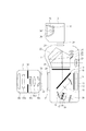
図1は本発明の実施形態にかかる撮像装置としてのカメラ、交換レンズ及び発光装置としてのストロボ装置の断面図を示している。なお、図1ではレンズ交換可能な、いわゆる、一眼レフタイプのカメラの構成を示しているがレンズ一体型のカメラであっても構わない。また、発光装置としてのストロボ装置もカメラ本体に着脱可能な外部ストロボとして説明しているが、カメラ本体に内蔵されたもの(内蔵ストロボ)でも構わない。 FIG. 1 is a cross-sectional view of a camera as an imaging device, an interchangeable lens, and a strobe device as a light emitting device according to an embodiment of the present invention. Although FIG. 1 shows a configuration of a so-called single-lens reflex camera capable of exchanging lenses, a lens-integrated camera may be used. Further, although the strobe device as the light emitting device has been described as an external strobe that can be attached to and detached from the camera body, it may be a built-in flash device (built-in strobe).
カメラ本体1はメカニカルシャッターであるシャッター10、光学ロウパスフィルター11、例えばCMOSやCCDといったエリアの蓄積型光電変換素子からなる撮像素子12を有している。
The
半透過性の主ミラー13と第1の反射ミラー14はともに撮影時には上部に跳ね上がる。第1の反射ミラー14で反射された光は、第1の反射ミラー14による撮像素子面と共役な近軸的結像面15、第2の反射ミラー16、赤外カットフィルター17、2つの開口部を有する絞り18、2次結像レンズ19を通って焦点検出用センサー20へ導かれる。
Both the semi-transmissive
焦点検出用センサー20は、例えばCMOSやCCDといったエリアの蓄積型光電変換素子からなり、図2に示すように絞り18の2つの開口部に対応して複数に分割された受光センサー部が20Aと20Bとの2対のエリアを有する構成になっている。第1の反射ミラー14から焦点検出用センサー20までの構成は、撮影画面内の任意の位置での像ずれ方式での焦点検出を可能とするものである。
The
主ミラー13で反射された光の一部は、拡散性を有するピント板21、ペンタプリズム22を通って接眼レンズ23へ、残りはさらに第3の反射ミラー24、集光レンズ25を通って被写体の輝度に関する情報を得るための測光用センサー26へ導かれる。
Part of the light reflected by the
測光用センサー26は、例えばCMOSやCCDといったエリアの蓄積型光電変換素子からなり、図3(a)に示すように撮像画面を複数分割したエリア毎に対応した被写体の輝度情報や色情報を出力する。複数分割したエリアについて本実施形態では7列×5行の35分割とし、35分割された各分割エリアを測光領域PD1〜PD35と呼ぶこととする。PD1〜PD35の各測光領域はさらに図3(b)に示すように細かな受光部画素に分かれており、かつこの受光部画素には一定の配列でカラーフィルターが付けられている。本例ではR(赤)、G(緑)、B(青)のいわゆる原色カラーフィルターがストライプ状に配列されたものとする。
The
さらに、カメラ本体1は、交換レンズを取り付けるマウント部27、装着された交換レンズと情報通信を行うための接点部28、ストロボ装置3を取り付ける接続部29を有している。
Further, the
交換レンズ2は、撮影レンズを構成する各光学レンズ30a〜30e、絞り31、カメラ本体1と情報通信を行うための接点部32、カメラ本体1に取り付けられるためのマウント部33を有している。
The
ストロボ装置3は、キセノン管などを光源とした発光部34、反射笠35、集光用のフレネルレンズ36、発光部34の発光量をモニターするためのモニターセンサー37、カメラ本体1に取り付けられるための取り付け部38を有している。
The
図4は本実施形態におけるカメラ本体1、交換レンズ2及びストロボ装置3の電気回路の構成例を表わすブロック図である。
FIG. 4 is a block diagram illustrating a configuration example of an electric circuit of the
カメラ本体1において、内部にALU、ROM、RAMやA/Dコンバータ、タイマー、シリアル通信ポート(SPI)等を内蔵したワンチップマイクロコンピュータからなる制御部41は、カメラ本体1全体の制御を行う。制御部41の具体的な制御フローについては後述する。
In the
焦点検出用センサー(AFセンサー)20及び測光用センサー(AEセンサー)26の出力信号は、制御部41のA/Dコンバータ入力端子に入力される。タイミングジェネレータ42は測光用センサー26の蓄積や読み出しを制御するためのタイミング信号等を生成する。
Output signals of the focus detection sensor (AF sensor) 20 and the photometry sensor (AE sensor) 26 are input to an A / D converter input terminal of the
信号処理回路43は、制御部41の指示に従って撮像素子12を制御して撮像素子12が出力する撮像信号をA/D変換して信号処理を行い、画像信号を得る。また、得られた画像信号を記録するにあたって、圧縮等の必要な画像処理を行う。DRAM等のメモリ44は、信号処理回路43が種々の信号処理を行う際のワーク用メモリとして使われたり、後述する表示部45に画像を表示する際のVRAMとして使われたりする。
The
液晶パネル等で構成されて各種撮影情報や撮像画像を表示する表示部45は、制御部41からの指示により表示制御される。フラッシュメモリ又は光ディスク等による記憶手段46は、撮像された画像信号を信号処理回路43から受け取り記憶する。
The
第1のモータードライバ47は、制御部41からの制御信号に基づいて、主ミラー13及び第1の反射ミラー14のアップ・ダウンやシャッター10のチャージを行うために第1のモーター48を駆動させる。
The
レリーズスイッチ49は撮影開始を指示するためのスイッチである。接点部28は、交換レンズ2と通信可能なように制御部41のシリアル通信ポートの入出力信号が接続される。接続部29は、ストロボ装置3と通信可能なように制御部41のシリアル通信ポートの入出力信号が接続される。シャッター駆動手段50は制御部41の出力端子に接続されてシャッター10を駆動させる。
The
交換レンズ2において、内部にALU、ROM、RAMやタイマー、シリアル通信ポート(SPI)等を内蔵したワンチップマイクロコンピュータからなるレンズ制御部51は、交換レンズ2全体の制御を行う。
In the
第2のモータードライバ52はレンズ制御部51からの制御信号に基づいて、焦点調節を行うために第2のモーター53を駆動させる。同様に、第3のモータードライバ54はレンズ制御部51からの信号に基づいて、絞り31の制御を行うために第3のモーター55を駆動させる。
The
焦点調節レンズの繰り出し量すなわち被写体距離に関する情報を得るための距離エンコーダー56は、レンズ制御部51の入力端子に接続される。交換レンズ2がズームレンズである場合に撮影時の焦点距離情報を得るためのズームエンコーダー57は、レンズ制御部51の入力端子に接続される。
A
接点部32は、カメラ本体1と通信可能なようにレンズ制御部51のシリアル通信ポートの入出力信号が接続される。交換レンズ2がカメラ本体1に装着されると接点部28と接点部32とが接続されて、制御部41とレンズ制御部51とのデータ通信が可能となる。
The input / output signal of the serial communication port of the
制御部41が焦点検出や露出演算を行うために必要なレンズ固有の光学的な情報はレンズ制御部51から制御部41へとデータ通信によって出力される。また、距離エンコーダー56、ズームエンコーダー57に基づいた被写体距離に関する情報や焦点距離情報もレンズ制御部51から制御部41へとデータ通信によって出力される。また、制御部41が焦点検出や露出演算を行った結果求められた焦点調節情報や絞り情報は制御部41からレンズ制御部51へとデータ通信によって出力される。レンズ制御部51は制御部41とのデータ通信で得た焦点調節情報に従って第2のモータードライバ52を制御し、絞り情報に従って第3のモータードライバ54を制御する。
The lens-specific optical information necessary for the
ストロボ装置3において、内部にALU、ROM、RAMやA/Dコンバータ、タイマー、シリアル通信ポート(SPI)等を内蔵したワンチップマイクロコンピュータからなるストロボ制御部61は、ストロボ装置3全体の制御を行う。昇圧部62は発光部34の発光に必要な300V程度の高圧電圧を作りその高圧電圧を充電する機能を有する。
In the
ストロボ装置3がカメラ本体1に装着されると接続部29と接続部38とが接続されて、制御部41とストロボ制御部61とのデータ通信が可能となる。ストロボ制御部61は制御部41から得る情報に従って昇圧部62を制御して発光部34の発光開始や発光停止を行うとともに、モニターセンサー37の検出量に関する情報を制御部41に対して出力する。また、ストロボ制御部61から制御部41へ発光部34の発光色情報も送信する。
When the
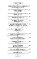
続いて、図5のフローチャートを用いてストロボ撮影を行う際の各種処理を説明する。不図示の電源スイッチがオンされると図5に示したフローチャートが開始され、ステップS101で制御部41は、レンズ制御部51と通信を行い焦点調節や測光に必要な交換レンズ2の各種情報を取得する。
Next, various processes when performing flash photography will be described using the flowchart of FIG. When a power switch (not shown) is turned on, the flowchart shown in FIG. 5 is started. In step S101, the
ステップS102で制御部41は、ストロボ制御部61に指示をして、十分な充電電圧となるように昇圧部62を動作させる。また、制御部41はストロボ制御部61と通信を行い、ストロボ装置3の発光色情報を取得する。
In step S102, the
ステップS103で制御部41は、焦点検出用センサー20に対して制御信号を出力して、焦点検出用センサー20による信号蓄積を行う。蓄積が終了すると制御部41は焦点検出用センサー20に蓄積された信号を読み出しながらA/D変換を行う。さらに読み込んだデジタルデータに対してシェーディング補正等の各種補正処理を行う。
In step S <b> 103, the
ステップS104で制御部41は、ステップS101で取得した交換レンズ2の各種情報と焦点検出用センサー20から得られているデジタルデータに基づいて、撮影画面各部に設けられた焦点検出領域の焦点状態を演算する。さらに焦点を合わせるべき焦点検出領域を決定する。ここで、焦点を合わせるべき焦点検出領域の決定は、操作部材などを用いて撮影者が任意の領域を指定することで決定してもよいし、所定のアルゴリズムに基づいて制御部41が決定してもよい。そして、制御部41は決定された焦点検出領域における焦点状態に従って合焦となるためのレンズ移動量を算出し、算出されたレンズ移動量に関する情報をレンズ制御部51に出力する。このレンズ移動量に関する情報に従ってレンズ制御部51は焦点調節用レンズを駆動させるように第2のモータードライバ52に制御信号を出力して、第2のモーター53を駆動させる。この一連の焦点調節動作により、決定した焦点検出領域に存在する被写体に対して合焦となる。なお、焦点調節用レンズを駆動させることで距離エンコーダー56から出力される情報が変化するので、交換レンズ2の各種情報の更新も行う。
In step S104, the
ステップS105で制御部41は、タイミングジェネレータ42を制御して測光用センサー26の蓄積制御及び蓄積された信号の読み出し制御を行う。これにより測光用センサー26は所定時間の電荷蓄積を行い、制御部41は複数画素の蓄積信号を順次読み出してA/D変換を行いRAMに格納する。RAMに格納された測光用センサー26の蓄積信号情報は測光領域(PD1〜PD35)毎にR、G、Bの各色別に加算処理を行いR(i)、G(i)、B(i)が算出される。続けてR(i)、G(i)、B(i)に所定の係数(M11〜M33)によるマトリクス演算が施されて、測光領域毎のリニア系での被写体輝度情報Br(i)及び被写体色情報Cx(i)、Cy(i)が算出される。
In step S105, the

i=1〜35
i = 1 to 35
測光領域毎のリニア系での被写体輝度情報Br(i)はさらに2を底とする対数圧縮系への変換関数処理とレンズ情報等光学的特性に基づく画面エリア毎の輝度情報の補正処理Sとを行い、対数圧縮系での被写体輝度情報B(i)とする。
B(i)=log2{Br(i)}×S(i)
i=1〜35
The subject luminance information Br (i) in the linear system for each photometric area is further converted into a logarithmic compression system having a base of 2 and correction processing S for luminance information for each screen area based on optical characteristics such as lens information. To obtain subject luminance information B (i) in the logarithmic compression system.
B (i) = log 2 {Br (i)} × S (i)
i = 1 to 35
ステップS106で制御部41は、ストロボ制御部61と通信を行い、発光を行うのに十分な充電電圧となっているかを判断する。発光を行うのに十分な充電電圧となっていなければ、十分な充電電圧となるまで充電を継続する。
In step S106, the
ステップS107で制御部41は、ステップS105で得られた測光領域毎の被写体輝度情報B(i)に対して重み付けをした重み付け演算により撮影画面全体の輝度情報を演算する。そして、このようにして演算された撮影画面全体の輝度情報と所定のプログラム線図とに基づいて、撮像素子12の蓄積時間(シャッター速度)、絞り値及び撮影感度を決定し、表示部45に表示させる。シャッター速度、絞り値及び撮影感度の一部が撮影者によって指定され予めプリセットされている場合は、そのプリセット値と組み合わせて最適な露出となる残りのパラメータを決定する。なお、以下では、決定されたシャッター速度と絞り値とのアペックス値に基づく露出値をEVTと呼ぶこととし、以下の関係式を満たすものとする。
EVT=Tv+Av
ここで、Tvはシャッター速度のアペックス値、Avは絞り値のアペックス値である。
In step S107, the
EVT = Tv + Av
Here, Tv is the apex value of the shutter speed, and Av is the apex value of the aperture value.
ステップS108で制御部41は、レリーズスイッチがオンであるか否かを判断する。レリーズスイッチがオンであればステップS109へ進み、レリーズスイッチがオンでなければステップS101へ戻る。
In step S108, the
ステップS109で制御部41は、ストロボ装置3で予備発光を行う前にストロボ装置3を発光させていない状態で測光を行うため、タイミングジェネレータ42を制御して測光用センサー26の蓄積制御及び蓄積された信号の読み出し制御を行う。これにより測光用センサー26は所定時間の電荷蓄積を行い、制御部41は複数画素の蓄積信号を順次読み出してA/D変換を行いRAMに格納する。RAMに格納された測光用センサー26の蓄積信号情報は測光領域(PD1〜PD35)毎にR、G、Bの各色別に加算処理を行いRp(i)、Gp(i)、Bp(i)が算出される。続けてRp(i)、Gp(i)、Bp(i)に所定の係数(M11〜M33)によるマトリクス演算が施されて、測光領域毎のリニア系での予備発光直前被写体輝度情報Pr(i)及び被写体色情報Cpx(i)、Cpy(i)が算出される。
In step S109, the
i=1〜35
i = 1 to 35
測光領域毎のリニア系での予備発光直前被写体輝度情報Pr(i)はさらに2を底とする対数圧縮系への変換関数処理とレンズ情報等光学的特性に基づく画面エリア毎の輝度情報の補正処理Sとを行い、対数圧縮系での予備発光直前被写体輝度情報P(i)とする。
P(i)=log2{Pr(i)}×S(i)
i=1〜35
The subject luminance information Pr (i) immediately before preliminary light emission in the linear system for each photometric area is further converted into a logarithmic compression system with a base of 2 and correction of luminance information for each screen area based on optical characteristics such as lens information. Processing S is performed to obtain subject luminance information P (i) immediately before preliminary light emission in the logarithmic compression system.
P (i) = log 2 {Pr (i)} × S (i)
i = 1 to 35
ステップS110で制御部41は、ストロボ制御部61と通信を行い本発光に先立って予備発光するように指示する。これによりストロボ制御部61は、モニターセンサー37の出力信号に基づき発光部34が予め定められた予備発光量だけ発光するように発光部34を発光させる。この予備発光が行われている間の被写体の測光情報を得るために、制御部41は、タイミングジェネレータ42を制御して測光用センサー26の所定の蓄積制御及び信号読み出し制御を行う。これにより測光用センサー26は所定時間の電荷蓄積を行い、制御部41は複数画素の蓄積信号を順次読み出してA/D変換を行いRAMに格納する。RAMに格納された測光用センサー26の蓄積信号情報は測光領域(PD1〜PD35)毎にR、G、Bの各色別に加算処理を行いRh(i)、Gh(i)、Bh(i)が算出される。続けてRh(i)、Gh(i)、Bh(i)に所定の係数(M11〜M33)によるマトリクス演算が施されて、測光領域毎のリニア系での予備発光時被写体輝度情報Hr(i)及び被写体色情報Chx(i)、Chy(i)が算出される。
In step S110, the
i=1〜35
i = 1 to 35
測光領域毎のリニア系での予備発光時被写体輝度情報Hr(i)はさらに2を底とする対数圧縮系への変換関数処理とレンズ情報等光学的特性に基づく画面エリア毎の輝度情報の補正処理Sとを行い、対数圧縮系での予備発光時被写体輝度情報H(i)とする。
H(i)=log2{Hr(i)}×S(i)
i=1〜35
The subject luminance information Hr (i) during preliminary light emission in the linear system for each photometric area is further converted into a logarithmic compression system with a base of 2 and correction of luminance information for each screen area based on optical characteristics such as lens information. Processing S is performed to obtain subject luminance information H (i) during preliminary light emission in the logarithmic compression system.
H (i) = log 2 {Hr (i)} × S (i)
i = 1 to 35
ステップS111で制御部41は、撮影時の発光量(以下、本発光量とする)の演算を行う。この演算処理については図6を用いて後述する。
In step S111, the
ステップS112で制御部41は、第1のモータードライバ47に制御信号を出力して第1のモーター48を駆動させ、主ミラー13及び第1の反射ミラー14を跳ね上げる。さらに、制御部41はレンズ制御部51にステップS107で決定した絞り値に関する絞り情報を出力する。この絞り情報に従ってレンズ制御部51は絞り31を駆動させるように第3のモータードライバ54に制御信号を出力して、第3のモーター55を駆動させる。これにより絞り31はステップS107で決定した絞り値に対応した開口径となる。
In step S112, the
ステップS113で制御部41は、シャッター駆動手段50に対して制御信号を出力し、シャッター10を開放状態にさせる。これにより撮像素子12に撮影レンズを通った光が入射して撮像が可能となる。そして、制御部41は、ステップS107で決定した蓄積時間と撮像感度に基づいて撮像素子12の信号蓄積が行われるように信号処理回路43に対して指示をする。
In step S <b> 113, the
また、制御部41は、撮像素子12による撮像に合わせて発光するようにストロボ制御部61に対して発光指示を行う。ストロボ制御部61は制御部41からの発光指示に従って、ステップS111で演算された本発光量となるようにモニターセンサー37の出力信号に基づき発光部34を発光させる。これによってストロボ装置3の発光を伴った撮像が行われる。
Further, the
撮像が終了すると制御部41はシャッター駆動手段50に対して制御信号を出力し、シャッター10を遮光状態にさせる。これにより撮像素子12に対する撮影レンズを通った光が遮断される。
When the imaging is completed, the
ステップS114で制御部41は、レンズ制御部51に対して絞り31を開放するように指示する。この指示に従ってレンズ制御部51は絞り31を駆動させるように第3のモータードライバ54に制御信号を出力して、第3のモーター55を駆動させる。これにより撮影レンズの絞りは開放状態となる。さらに、制御部41は第1のモータードライバ47に制御信号を出力して、第1のモーター48を駆動させて主ミラー13及び第1の反射ミラー14をダウンさせる。
In step S114, the
ステップS115で制御部41は、信号処理回路43に対して指示を行い、撮像素子12が出力する撮像信号をA/D変換して補正処理や補間処理を行わせる。
In step S115, the
ステップS116で制御部41は、補正処理や補間処理が行われた画像信号に対してホワイトバランス調整を行うように信号処理回路43に指示を行う。
In step S116, the
ステップS117で制御部41は、ホワイトバランス調整が行われた画像信号を記録ファイルフォーマットに圧縮変換して記憶手段46に記憶するように信号処理回路43に対して指示を行う。
In step S117, the
以上でストロボ撮影を行う際の各種処理が終了する。 This completes the various processes for performing flash photography.
次に、ステップS111で行う本発光量演算に関する処理について図6のフローチャートを用いて説明する。 Next, the process related to the main light emission amount calculation performed in step S111 will be described with reference to the flowchart of FIG.
ステップS151で制御部41は、測光領域毎に予備発光直前の予備発光直前被写体輝度情報P(i)と予備発光時被写体輝度情報H(i)とから、予備発光時のストロボ装置3から照射される光の反射光分のみの輝度値D(i)を演算する。予備発光直前被写体輝度情報P(i)と予備発光時被写体輝度情報H(i)とはそれぞれ圧縮系での値であることより、それぞれのべき乗をとって伸長させてから差分をとり、差分値を対数圧縮して下式の演算を行う。
D(i)=log2(2H(i)−2P(i))
i=1〜35
In step S151, the
D (i) = log 2 (2 H (i) −2 P (i) )
i = 1 to 35
また、測光領域毎に予備発光直前被写体色情報Cpx(i)、Cpy(i)と予備発光時被写体色情報Chx(i)、Chy(i)とから、予備発光時のストロボ装置3から照射される光の反射光分のみの被写体色情報Ex(i)、Ey(i)を演算する。
Ex(i)=Chx(i)−Cpx(i)
Ey(i)=Chy(i)−Cpy(i)
i=1〜35
Further, for each photometric area, the subject color information Cpx (i), Cpy (i) immediately before preliminary light emission and the subject color information Chx (i), Chy (i) at preliminary light emission are irradiated from the
Ex (i) = Chx (i) -Cpx (i)
Ey (i) = Chy (i) -Cpy (i)
i = 1 to 35
ステップS152で制御部41は、測光領域毎に予備発光直前被写体輝度情報P(i)と予備発光時被写体輝度情報H(i)とから、輝度値の比R(i)を演算する。
R(i)=H(i)−P(i)
予備発光直前被写体輝度情報P(i)と予備発光時被写体輝度情報H(i)とはそれぞれ対数圧縮系での値であることより、この差分をとることは輝度値の比をとることと等価である。
In step S152, the
R (i) = H (i) -P (i)
Since the subject luminance information P (i) immediately before preliminary light emission and the subject luminance information H (i) at the time of preliminary light emission are values in a logarithmic compression system, taking this difference is equivalent to taking a ratio of luminance values. It is.
ここで、輝度値の比を求めることにより、35分割された各測光領域において輝度値の比の値が一致する測光領域は被写体までの距離が一致しているとみなすことができる。 Here, by obtaining the ratio of the luminance values, it can be considered that the distances to the subject are the same in the photometric areas where the ratio values of the luminance values match in each of the 35 photometric areas divided.
ステップS153で制御部41は、レンズ制御部51から得られる距離エンコーダー56の情報、すなわち被写体距離に関する情報D(以下、距離情報Dとする)に基づいて、閾値LVL0及びLVL1を演算する。閾値LVL0はレンズ制御部51から得られる距離情報Dと予備発光時の発光量に関する情報C2とから、距離情報Dが表す距離に標準的な反射率の被写体が存在する場合の予備発光の反射光分のみの輝度値を想定して計算される。閾値LVL0は距離情報Dが表す距離に標準的な反射率の被写体が存在する場合の予備発光の反射光分のみの輝度値よりも少し高くなるように決める。これは、距離情報Dが実際は多少の誤差を持つことを考慮して、その誤差分程度閾値LVL0を高くしておき、実際の標準的な反射率の被写体が存在する場合の予備発光の反射光分のみの輝度値がLVL0よりも高くならないようにするためである。
LVL0=−log2(D)×2+C2
In step S153, the
LVL0 = −log 2 (D) × 2 + C2
一方、閾値LVL1は閾値LVL0に対してC3を減じて決定する。C3は実際の標準的な反射率の被写体が存在する場合の予備発光の反射光分のみの輝度値が閾値LVL1を下回らないように、距離情報Dの誤差などを考慮して決定する。
LVL1=LVL0−C3
このように、一般的な被写体の予備発光時の反射光分のみの輝度値は閾値LVL0及びLVL1の間に入る前提で以下の本発光量決定のための演算が行われる。
On the other hand, the threshold value LVL1 is determined by subtracting C3 from the threshold value LVL0. C3 is determined in consideration of an error of the distance information D so that the luminance value of only the reflected light of the preliminary light emission when there is an actual standard reflectance subject does not fall below the threshold value LVL1.
LVL1 = LVL0-C3
As described above, the following calculation for determining the main light emission amount is performed on the assumption that the luminance value of only the reflected light during preliminary light emission of a general subject falls between the threshold values LVL0 and LVL1.
なお、レンズ交換可能な一眼レフタイプのカメラの場合には、装着されたレンズによっては距離エンコーダーを持っておらず距離情報Dが得られないこともある。その場合の閾値LVL0及びLVL1の決定方法は以下のようにする。 In the case of a single-lens reflex type camera with interchangeable lenses, the distance information D may not be obtained because the lens attached is not equipped with a distance encoder. In this case, the thresholds LVL0 and LVL1 are determined as follows.
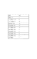
装着された交換レンズが距離エンコーダーを持っていない場合、ステップS101で取得した撮影レンズの焦点距離情報に基づいて、図8に示すtable1を参照して閾値LVL0を決定する。
LVL0=table1(f)
If the attached interchangeable lens does not have a distance encoder, the threshold LVL0 is determined with reference to table1 shown in FIG. 8 based on the focal length information of the photographing lens acquired in step S101.
LVL0 = table1 (f)
例えば、撮影レンズの焦点距離が28mmであれば、0.5mの距離に標準的な反射率の被写体があった場合の予備発光の反射光分のみの輝度値を閾値LVL0とする。一般的に、この焦点距離の撮影レンズを使って撮影を行う場合、0.5mよりも近距離の被写体を撮影する頻度は極めて低い。そのため、実際の予備発光の反射光分のみの輝度値は閾値LVL0よりも低くなる可能性が高い。以下同様に、焦点距離が50mmの撮影レンズであれば0.8mの距離に標準的な反射率の被写体があった場合の予備発光の反射光分のみの輝度値を閾値LVL0とするという考え方で図8のtable1は構成されている。本実施形態では、図8に示すように撮影レンズの焦点距離に対してはある程度のステップで区切っているが、ステップ数や各ステップの幅、あるいは各ステップに対応付けする被写体距離は図8に例示したものに限らない。 For example, if the focal length of the photographic lens is 28 mm, the threshold value LVL0 is the luminance value of only the reflected light of the preliminary light emission when there is an object with a standard reflectance at a distance of 0.5 m. In general, when photographing using a photographing lens having this focal length, the frequency of photographing a subject at a short distance of 0.5 m is extremely low. Therefore, there is a high possibility that the luminance value of only the reflected light of the actual preliminary light emission is lower than the threshold value LVL0. Similarly, in the case of a photographic lens with a focal length of 50 mm, the threshold value LVL0 is set to the luminance value of only the reflected light of the preliminary light emission when there is an object having a standard reflectance at a distance of 0.8 m. Table 1 in FIG. 8 is configured. In this embodiment, as shown in FIG. 8, the focal length of the photographing lens is divided by a certain number of steps, but the number of steps, the width of each step, or the subject distance associated with each step is shown in FIG. It is not restricted to what was illustrated.
一方、閾値LVL1は閾値LVL0からC1を減じて決定する。C1は経験則的に被写体の予備発光の反射光分のみの輝度値がLVL1を下回らないように決められる。例えば、焦点距離が50mmの撮影レンズでストロボ撮影する場合に被写体距離が6.4mを超える被写体を主被写体にして撮影する確率は極めて低いとすれば、閾値LVL0に対して被写体からの反射光は6段分の範囲に収まると考えてC1は6とする。
LVL1=LVL0−C1
閾値LVL0及びLVL1はともに対数圧縮系での値である。
On the other hand, the threshold value LVL1 is determined by subtracting C1 from the threshold value LVL0. As a rule of thumb, C1 is determined so that the luminance value of only the reflected light of the preliminary light emission of the subject does not fall below LVL1. For example, when shooting with a shooting lens having a focal length of 50 mm, if the probability of shooting with a subject whose subject distance exceeds 6.4 m as the main subject is extremely low, the reflected light from the subject with respect to the threshold LVL0 is C1 is set to 6 considering that it is within the range of 6 steps.
LVL1 = LVL0-C1
The threshold values LVL0 and LVL1 are both values in the logarithmic compression system.
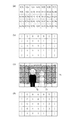
ステップS154で制御部41は、後述する基準領域の選択において対象となる測光領域(以下、対象領域とする)を限定する係数K(i)を所定の初期値に設定する。係数K(i)は図7(a)にあるように35分割された各測光領域に対してそれぞれ0または1が設定される。初期値は、同図(b)に示すように、通常撮影時に主被写体が存在する可能性が低いと想定される画面周辺部のK(1)〜(8)、(14)、(15)、(22)、(23)、(28)、(29)、(35)のエリアを0としで、それ以外のエリアは1としている。
In step S154, the
ステップS155で制御部41は、ステップS151で演算した測光領域毎の輝度値D(i)をステップS153で決定した閾値LVL0及びLVL1と比較する。そして、D(i)>LVL0またはD(i)<LVL1となる測光領域に対して、そのエリアの係数K(i)を0とする。
In step S155, the
これによりガラス等の鏡面物体からの正反射により輝度値D(i)が異常に高くなっている測光領域やストロボ装置3が照射する光が届かないくらいに距離が離れていて輝度値D(i)が非常に低くなっている測光領域の係数K(i)が0となる。なお、ステップS154で設定された初期値が0である測光領域については、輝度値D(i)の大きさによらず0とするので、輝度値D(i)と閾値LVL0及びLVL1との比較は行わなくてもよい。
As a result, the brightness value D (i) is so far away that the light metering region where the luminance value D (i) is abnormally high due to specular reflection from a specular object such as glass or the light irradiated by the
ステップ156で制御部41は、予めROM内に格納している、金屏風が存在する測光領域を判別するための特定の条件である判別用標準パラメータ(以下、標準パラメータとする)をステップS102で取得したストロボ装置3の発光色情報に基づいて補正する。金屏風が存在する測光領域を判別するための標準パラメータは図10に示す4つのパラメータであり、それぞれの値は、発光装置として標準的な発光色及び発光条件で金屏風に光を照射した際の反射光の色範囲に基づいて設定される。発光装置から照射される光の発光色は製品の機種間差による発光色差や発光条件の差による変化がある程度存在するので、装着したストロボ装置3から取得した発光色情報に基づいて発光色に適したように標準パラメータを補正する。また、このような補正を行うことで、ストロボ装置3側で発光色を意図的に変更する発光光源切替えやフィルターアタッチメントの取り付けがあった場合でも、変更した発光色に応じた発光色情報が取得できれば金屏風が存在するエリアを判別可能である。
In step S156, the
以下では、標準パラメータをそれぞれExmin、Exmax、Eymin、Eymaxとし、標準パラメータを補正した後のデータである補正後パラメータをそれぞれExcmin、Excmax、Eycmin、Eycmaxとする。 In the following description, the standard parameters are Exmin, Exmax, Eymin, and Eymax, respectively, and the corrected parameters that are data after correcting the standard parameters are Excmin, Excmax, Eycmin, and Eycmax, respectively.
そして、補正後パラメータと、ステップS151で演算された測光領域毎の予備発光時のストロボ装置3から照射される光の反射光分のみの被写体色情報Ex(i)、Ey(i)とを比較する。以下のようにEx(i)、Ey(i)がともに補正後パラメータの範囲内に存在する場合、そのエリアを金屏風が存在するエリアとみなす。すなわち、測光領域内に金屏風が存在していたとしても、以下の条件を満たさないほど金屏風の占める割合が小さい測光領域であれば、金屏風が存在するエリアとしない。
Excmin≦Ex(i) ≦Excmax
Eycmin≦Ey(i) ≦Eycmax
Then, the corrected parameters are compared with subject color information Ex (i) and Ey (i) for only the reflected light of the light emitted from the
Excmin ≦ Ex (i) ≦ Excmax
Eycmin ≦ Ey (i) ≦ Eycmax
ステップS157で制御部41は、ステップS156での判別結果から、金屏風が存在する測光領域があるか否かを判断し、金屏風が存在する測光領域がある場合にはステップS158へ進み、金屏風が存在する測光領域がない場合にはステップS159へ進む。
In step S157, the
ステップS158で制御部41は、金屏風が存在する測光領域の係数K(i)を0とする。なお、ステップS154やS155でK(i)=0となっている測光領域については金屏風が存在する測光領域か否かによらず0とするので、ステップS156において比較を行わなくてもよい。また、ステップS156での判別結果から金屏風が存在する測光領域があるか否かを判断し、金屏風が存在する測光領域がステップS154やS155でK(i)=0となっている測光領域だけである場合には、ステップS158を省略してもよい。
In step S158, the
ステップS158における係数K(i)の決定について、図7(c)に示すような撮影構図で撮影を行う場合を例にして説明する。図7(c)では、主被写体72、73の背後に金屏風71が存在している。そのため、35分割された測光領域の多くで金屏風の占める割合が大きく、金屏風の色情報が取得できるPD1〜8、9、11、13〜16、18、20〜23、27、28において、金屏風であることを示すEx(i)、Ey(i)が取得される。これらの測光領域の係数K(i)も0に変更すると、図7(d)に示すようになる。以上のようにして、基準領域の選択を行う際の対象領域を決定する。
The determination of the coefficient K (i) in step S158 will be described by taking as an example the case of shooting with the shooting composition as shown in FIG. In FIG. 7C, a
次に、ステップ159で制御部41は、K(i)=1である測光領域の中で輝度値の比R(i)が最大の値を示す測光領域を選択し、基準領域とする。上記のように、K(i)=1である測光領域は主被写体は存在する可能せいが高い測光領域であって、その中でR(i)が最大の値を示す測光領域は最も主被写体の存在する可能性が高いと考えられる。
Next, in
ステップS160で制御部41は、35分割された各測光領域において輝度値の比R(i)と基準値baseRとの差RR(i)を演算する。
RR(i)=baseR−R(i)
輝度値の比R(i)と基準値baseRとはともに対数圧縮系での値なのでRR(i)は基準領域のR(i)とその他の測光領域のR(i)との比を演算していることになる。このRR(i)の値が小さくなる測光領域というのは、基準領域に存在する被写体と略等しい距離に被写体が存在するとみなせる測光領域である。一方で、RR(i)の値が正の方向に大きい測光領域というのは基準領域に存在する被写体よりも遠い距離に被写体が存在するとみなせる測光領域である。逆に、RR(i)の値が負の方向に大きい測光領域というのは基準領域に存在する被写体よりも近い距離に被写体が存在するとみなせる測光領域である。
In step S160, the
RR (i) = baseR−R (i)
Since both the luminance value ratio R (i) and the reference value baseR are values in a logarithmic compression system, RR (i) calculates the ratio of R (i) in the reference area and R (i) in the other photometric areas. Will be. The photometric area in which the value of RR (i) is small is a photometric area in which it can be assumed that the subject exists at a distance substantially equal to the subject existing in the reference area. On the other hand, a photometric area in which the value of RR (i) is large in the positive direction is a photometric area in which it can be assumed that the subject exists at a distance farther than the subject existing in the reference area. Conversely, a photometric area in which the value of RR (i) is large in the negative direction is a photometric area in which it can be assumed that the subject is present at a distance closer to the subject existing in the reference area.
ステップS161で制御部41は、35分割された各測光領域において演算されたRR(i)に基づいて重み付け係数W(i)を決定する。具体的には、各測光領域のRR(i)の値に基づいて図9に示したtable2を用いてW(i)を決定する
W(i)=table2(RR(i))
table2によれば、RR(i)の値が0に近い測光領域ほどW(i)は大きく、RR(i)の値の絶対値が大きい測光領域ほどW(i)は小さい。すなわち、基準領域の重み付けが最も大きい。前述したように、RR(i)の値が0に近い測光領域ほど基準領域の被写体と等しい距離に被写体が存在する測光領域であり、基準領域の被写体と同様の被写体あるいは基準領域の被写体と同程度に重要な被写体が存在する可能性が高いためである。一方、RR(i)の値の絶対値が大きい測光領域ほど基準領域の被写体と距離の大きく異なる被写体が存在する測光領域であり、基準領域の被写体と同程度に重要な被写体が存在する可能性が低いためである。上記の方法によれば、ステップS154〜158においてK(i)の値が0とされて対象領域から外された測光領域においても、結果としてRR(i)の値が0に近い値であればW(i)は大きくなる。
In step S161, the
According to table 2, W (i) is larger in the photometric area where the value of RR (i) is close to 0, and W (i) is smaller in the photometric area where the absolute value of RR (i) is larger. That is, the reference area is most weighted. As described above, a photometric area in which the value of RR (i) is closer to 0 is a photometric area where the subject exists at a distance equal to the subject in the reference area, and is the same as the subject in the reference area or the same subject as that in the reference area. This is because there is a high possibility that there is a subject that is so important. On the other hand, a photometric area in which the absolute value of RR (i) is larger is a photometric area where there is a subject whose distance is significantly different from the subject in the reference area. Is low. According to the above method, even in the photometric area where the value of K (i) is set to 0 in steps S154 to S158 and excluded from the target area, if the value of RR (i) is a value close to 0 as a result, W (i) increases.
そのため、撮影毎に撮影画面内での主被写体位置が移動している場合や同一シーンを少しだけ構図変更して撮影する場合などにおいても、ほぼ同様な本発光量が演算されて撮影毎に異なる露出結果になることを防止し、安定した撮影結果が期待できる。金屏風は撮像装置や発光装置と向き合う角度により光の反射状況が大きく変化し、発光装置から照射される光の反射光分のみの輝度値D(i)も大きく変化する。そのため、被写体色情報から金屏風が存在する測光領域と判別された測光領域であっても、発光装置から照射される光の反射光分が大きくないような光の反射状況であればRR(i)の値が0に近くW(i)が高くても良好な画像を得ることはできる。 Therefore, even when the main subject position moves on the shooting screen for each shooting or when shooting the same scene with a slight composition change, almost the same main light emission amount is calculated and differs for each shooting. It is possible to prevent exposure results and to expect stable shooting results. In the gold screen, the reflection state of light greatly changes depending on the angle facing the imaging device and the light emitting device, and the luminance value D (i) of only the reflected light of the light emitted from the light emitting device also changes greatly. Therefore, even if it is a photometric area determined from the subject color information as a photometric area where a gold screen is present, if the reflected light of the light emitted from the light emitting device is not large, RR (i A good image can be obtained even if the value of) is close to 0 and W (i) is high.
ステップS162で制御部41は、ステップS161で決定したW(i)に従って各測光領域の輝度値D(i)の重み付け演算を行う。
AVE=Σ(D(i)×W(i))/ΣW(i)
この重み付け演算により、撮影画面全体の予備発光時のストロボ装置3から照射される光の反射光分のみの輝度値の加重平均値AVEが演算される。
In step S162, the
AVE = Σ (D (i) × W (i)) / ΣW (i)
By this weighting calculation, the weighted average value AVE of the luminance values of only the reflected light of the light emitted from the
ステップS163で制御部41は、ステップS107で決定された露出値EVTとステップS161で演算された加重平均値AVEから本発光量情報Gを演算する。
G=EVT−AVE
上記の式のように、Gは予備発光時の発光量に対する相対値を示していて、実質的には本発光量を示している。演算された本発光量情報Gは制御部41からストロボ制御部61に伝えられ、ステップS113では本発光量情報Gに従ってストロボ装置3の本発光が行われる。
In step S163, the
G = EVT-AVE
As in the above equation, G represents a relative value with respect to the light emission amount during preliminary light emission, and substantially represents the main light emission amount. The calculated main light emission amount information G is transmitted from the
以上のように、撮影画面内に金屏風が存在する場合、金屏風が存在する測光領域を本発光量の演算を行う際に基準とする基準領域を選択する対象領域から除外することで、撮影者が意図する主被写体に対して適正な発光量を演算することができる。それによって、撮影画面内に金屏風が存在する場合であっても良好な画像を得ることができる。 As described above, when a gold screen is present in the shooting screen, the photometry area where the gold screen is present is excluded from the target region for selecting the reference region to be used as a reference when performing the main flash amount calculation. An appropriate amount of light emission can be calculated for the main subject intended by the person. Thereby, a good image can be obtained even when a gold screen exists in the shooting screen.
以上、本発明の好ましい実施形態について説明したが、本発明はこれらの実施形態に限定されず、その要旨の範囲内で種々の変形及び変更が可能である。 As mentioned above, although preferable embodiment of this invention was described, this invention is not limited to these embodiment, A various deformation | transformation and change are possible within the range of the summary.
例えば、上記の実施形態では、図6のステップS156にて、金屏風が存在する測光領域の判別をストロボ装置3の予備発光時に取得した被写体色情報を用いて行う例を説明した。これはストロボ装置3の光を照射することで金屏風に最も強く光を照射している光源が特定でき、金屏風が存在するか否かの判別が容易になるからである。しかしながら、照明光源色に影響されず被写体の色検出ができる構成であれば、ストロボ装置3の予備発光時以外に取得した被写体色情報で金屏風が存在する測光領域の判別を行っても構わない。
For example, in the above embodiment, an example has been described in which the photometric area in which the gold screen is present is determined using the subject color information acquired during the preliminary light emission of the
また、上記の実施形態では、図6のステップS156にてストロボ装置3から送信された発光色情報により金屏風が存在する測光領域を判別するための判別用標準パラメータを補正する例を説明した。しかし、予備発光時のストロボ装置3から照射される光の反射光分のみの被写体色情報Ex(i)、Ey(i)をストロボ装置3からの発光色情報により補正して、標準パラメータExmin、Exmax、Eymin、Eymaxと比較する方法も考えられる。さらには、予備発光時のストロボ装置3から照射される光の反射光分のみの被写体色情報Ex(i)、Ey(i)を演算する際に使うマトリクス演算係数(M11〜M33)を補正する手法も考えられる。
In the above-described embodiment, the example in which the determination standard parameter for determining the photometric area where the gold screen is present is corrected based on the light emission color information transmitted from the
また、上記の実施形態では、色情報が特定の条件を満たす測光領域として金屏風が存在する測光領域を基準領域を選択する対象領域から除外する例を説明したが、金屏風と同様の特性を有するものであれば、その他の光反射物が存在する測光領域であってもよい。 In the above embodiment, the example in which the photometric area where the gold screen exists as a photometric area where the color information satisfies a specific condition is excluded from the target area for selecting the reference area. If it has, it may be a photometric area in which other light reflectors exist.
また、上記の実施形態では、測光用センサー26を輝度情報取得用のセンサーと色情報取得用のセンサーとして用いて被写体の輝度情報や色情報を取得する例を説明したが、輝度情報取得用のセンサーと色情報取得用のセンサーとをそれぞれ設けた構成でもよい。また、同一のセンサーを輝度情報取得用のセンサーと色情報取得用のセンサーとして用いる場合、撮像素子12を測光用センサー26の代わりに用いて被写体の輝度情報や色情報を取得してもよい。
In the above-described embodiment, the example in which the luminance information and the color information of the subject are acquired using the
1 カメラ本体
2 交換レンズ
3 ストロボ装置
12 撮像素子
20 焦点検出用センサー
26 測光用センサー
41 制御部
43 信号処理回路
51 レンズ制御部
61 ストロボ制御部
DESCRIPTION OF
Claims (8)
複数の測光領域のそれぞれに対応した複数の輝度情報を取得する輝度情報取得手段と、
前記複数の測光領域のそれぞれに対応した複数の色情報を取得する色情報取得手段と、
前記輝度情報取得手段により取得した輝度情報を用いて前記発光装置の本発光量を演算する演算手段と、
前記複数の測光領域の中から、前記演算手段により前記発光手段の本発光量を演算する際の基準領域を選択する選択手段と、
前記複数の測光領域の中から、前記選択手段により前記基準領域の選択を行う際の対象領域を決定する決定手段と、を有し、
前記決定手段は、前記色情報取得手段により取得した色情報が特定の条件を満たす測光領域を前記対象領域から除外し、
前記演算手段は、前記選択手段により選択された基準領域に対応した輝度情報に基づいて前記複数の輝度情報の重み付け演算を行い、前記本発光量を演算することを特徴とする撮像装置。 An imaging device capable of photographing using a light emitting device,
Luminance information acquisition means for acquiring a plurality of luminance information corresponding to each of a plurality of photometric areas;
Color information acquisition means for acquiring a plurality of color information corresponding to each of the plurality of photometric areas;
A calculation means for calculating a main light emission amount of the light emitting device using the luminance information acquired by the luminance information acquisition means;
A selection means for selecting a reference area for calculating the main light emission amount of the light emitting means by the calculating means from the plurality of photometric areas;
Determining means for determining a target area when performing selection of the reference area by the selection means from the plurality of photometric areas;
The determining means excludes the photometric area where the color information acquired by the color information acquiring means satisfies a specific condition from the target area,
The imaging apparatus according to claim 1, wherein the calculation means calculates the main light emission amount by performing a weighting calculation of the plurality of luminance information based on the luminance information corresponding to the reference region selected by the selection means.
複数の測光領域のそれぞれに対応した複数の輝度情報を取得する輝度情報取得ステップと、
前記複数の測光領域のそれぞれに対応した複数の色情報を取得する色情報取得ステップと、
前記輝度情報取得ステップで取得した輝度情報を用いて前記発光装置の本発光量を演算する演算ステップと、
前記複数の測光領域の中から、前記演算ステップで前記発光手段の本発光量を演算する際の基準領域を選択する選択ステップと、
前記複数の測光領域の中から、前記選択ステップで前記基準領域の選択を行う際の対象領域を決定する決定ステップと、を有し、
前記決定ステップは、前記色情報取得ステップで取得した色情報が特定の条件を満たす測光領域を前記対象領域から除外し、
前記演算ステップは、前記選択ステップで選択された基準領域に対応した輝度情報に基づいて前記複数の輝度情報の重み付け演算を行い、前記本発光量を演算することを特徴とする撮像装置の制御方法。 A method for controlling an imaging device capable of photographing using a light emitting device,
A luminance information acquisition step for acquiring a plurality of luminance information corresponding to each of a plurality of photometric areas;
A color information acquisition step of acquiring a plurality of color information corresponding to each of the plurality of photometric areas;
A calculation step of calculating a main light emission amount of the light-emitting device using the luminance information acquired in the luminance information acquisition step;
A selection step of selecting a reference region when calculating the main light emission amount of the light emitting means in the calculation step from the plurality of photometric regions;
A determination step of determining a target region when selecting the reference region in the selection step from the plurality of photometric regions;
The determining step excludes the photometric area where the color information acquired in the color information acquiring step satisfies a specific condition from the target area,
The method of controlling an imaging apparatus, wherein the calculating step performs weighting calculation of the plurality of pieces of luminance information based on luminance information corresponding to the reference region selected in the selecting step, and calculates the main light emission amount. .
Priority Applications (3)
| Application Number | Priority Date | Filing Date | Title |
|---|---|---|---|
| JP2011113911A JP2012242676A (en) | 2011-05-20 | 2011-05-20 | Imaging apparatus, and control method |
| US13/474,427 US8831414B2 (en) | 2011-05-20 | 2012-05-17 | Imaging apparatus, light emitting device, imaging system, and control method |
| CN201210158752.1A CN102799049B (en) | 2011-05-20 | 2012-05-21 | Imaging apparatus, light emitting device, imaging system, and control method |
Applications Claiming Priority (1)
| Application Number | Priority Date | Filing Date | Title |
|---|---|---|---|
| JP2011113911A JP2012242676A (en) | 2011-05-20 | 2011-05-20 | Imaging apparatus, and control method |
Publications (2)
| Publication Number | Publication Date |
|---|---|
| JP2012242676A true JP2012242676A (en) | 2012-12-10 |
| JP2012242676A5 JP2012242676A5 (en) | 2014-07-03 |
Family
ID=47174988
Family Applications (1)
| Application Number | Title | Priority Date | Filing Date |
|---|---|---|---|
| JP2011113911A Pending JP2012242676A (en) | 2011-05-20 | 2011-05-20 | Imaging apparatus, and control method |
Country Status (3)
| Country | Link |
|---|---|
| US (1) | US8831414B2 (en) |
| JP (1) | JP2012242676A (en) |
| CN (1) | CN102799049B (en) |
Cited By (1)
| Publication number | Priority date | Publication date | Assignee | Title |
|---|---|---|---|---|
| JPWO2015136644A1 (en) * | 2014-03-12 | 2017-04-06 | パイオニア株式会社 | Imaging apparatus, program, and imaging system |
Families Citing this family (7)
| Publication number | Priority date | Publication date | Assignee | Title |
|---|---|---|---|---|
| US9411212B2 (en) * | 2013-01-25 | 2016-08-09 | Canon Kabushiki Kaisha | Illumination apparatus which is arrangeable so as to surround an image capturing lens |
| CN104185340A (en) * | 2013-05-28 | 2014-12-03 | 深圳富泰宏精密工业有限公司 | Flashlight brightness control circuit and portable terminal |
| US9525811B2 (en) | 2013-07-01 | 2016-12-20 | Qualcomm Incorporated | Display device configured as an illumination source |
| CN104702849B (en) * | 2014-01-10 | 2018-03-30 | 杭州海康威视数字技术股份有限公司 | A kind of thermal camera and its infrared lamp luminance regulating method |
| US9503654B2 (en) * | 2014-05-30 | 2016-11-22 | Intel Corporation | Automatic anti-glare exposures for imaging devices |
| US9961248B2 (en) * | 2014-09-10 | 2018-05-01 | Canon Kabushiki Kaisha | Imaging system, illumination device, and control method |
| TWI608735B (en) * | 2017-03-13 | 2017-12-11 | 晶睿通訊股份有限公司 | Image capturing device and brightness adjusting method |
Citations (5)
| Publication number | Priority date | Publication date | Assignee | Title |
|---|---|---|---|---|
| JPH05119365A (en) * | 1991-05-23 | 1993-05-18 | Nikon Corp | Automatic dimmer for camera |
| JP2002006360A (en) * | 2000-06-26 | 2002-01-09 | Nikon Corp | Flash photographing controller and camera |
| JP2005065186A (en) * | 2003-08-20 | 2005-03-10 | Sony Corp | Image pickup unit |
| JP2005196252A (en) * | 2003-12-26 | 2005-07-21 | Konica Minolta Photo Imaging Inc | Object region detecting device, photographing device, target region detecting method and computer program |
| JP2005275265A (en) * | 2004-03-26 | 2005-10-06 | Canon Inc | Image pickup device, image pickup method, and computer program |
Family Cites Families (6)
| Publication number | Priority date | Publication date | Assignee | Title |
|---|---|---|---|---|
| JP3839901B2 (en) * | 1997-05-13 | 2006-11-01 | キヤノン株式会社 | Camera system |
| CN101010943B (en) * | 2005-04-26 | 2010-04-21 | 佳能株式会社 | Image taking device and its controlling method |
| US20070031060A1 (en) * | 2005-08-04 | 2007-02-08 | Canon Kabushiki Kaisha | Image processing apparatus, method for calculating white balance evaluation value, program including program code for realizing the method for calculating white balance evaluation value, and storage medium for storing the program |
| JP4976086B2 (en) * | 2006-09-14 | 2012-07-18 | 株式会社リコー | Buck-boost DC-DC converter |
| JP5228318B2 (en) * | 2006-12-07 | 2013-07-03 | 株式会社ニコン | Camera and flash output calculation program |
| US7894715B2 (en) * | 2008-03-31 | 2011-02-22 | Canon Kabushiki Kaisha | Image pickup apparatus, camera system, and control method for image pickup apparatus |
-
2011
- 2011-05-20 JP JP2011113911A patent/JP2012242676A/en active Pending
-
2012
- 2012-05-17 US US13/474,427 patent/US8831414B2/en not_active Expired - Fee Related
- 2012-05-21 CN CN201210158752.1A patent/CN102799049B/en not_active Expired - Fee Related
Patent Citations (5)
| Publication number | Priority date | Publication date | Assignee | Title |
|---|---|---|---|---|
| JPH05119365A (en) * | 1991-05-23 | 1993-05-18 | Nikon Corp | Automatic dimmer for camera |
| JP2002006360A (en) * | 2000-06-26 | 2002-01-09 | Nikon Corp | Flash photographing controller and camera |
| JP2005065186A (en) * | 2003-08-20 | 2005-03-10 | Sony Corp | Image pickup unit |
| JP2005196252A (en) * | 2003-12-26 | 2005-07-21 | Konica Minolta Photo Imaging Inc | Object region detecting device, photographing device, target region detecting method and computer program |
| JP2005275265A (en) * | 2004-03-26 | 2005-10-06 | Canon Inc | Image pickup device, image pickup method, and computer program |
Cited By (1)
| Publication number | Priority date | Publication date | Assignee | Title |
|---|---|---|---|---|
| JPWO2015136644A1 (en) * | 2014-03-12 | 2017-04-06 | パイオニア株式会社 | Imaging apparatus, program, and imaging system |
Also Published As
| Publication number | Publication date |
|---|---|
| US20120294600A1 (en) | 2012-11-22 |
| US8831414B2 (en) | 2014-09-09 |
| CN102799049B (en) | 2015-07-08 |
| CN102799049A (en) | 2012-11-28 |
Similar Documents
| Publication | Publication Date | Title |
|---|---|---|
| US9503616B2 (en) | Image capturing apparatus | |
| US7414231B2 (en) | Focus-state detecting device, image sensing apparatus and image sensing system having same and lens unit mounted thereon | |
| JP2012242676A (en) | Imaging apparatus, and control method | |
| JP5597078B2 (en) | Imaging apparatus and control method thereof | |
| JP6046905B2 (en) | Imaging apparatus, exposure control method, and program | |
| US10999523B2 (en) | Image pickup apparatus, method for controlling image pickup apparatus, and storage medium for controlling flash photography when a still image is imaged | |
| JP4931250B2 (en) | Imaging apparatus and control method | |
| JP6336337B2 (en) | Imaging apparatus, control method therefor, program, and storage medium | |
| US10212344B2 (en) | Image capturing device and control method capable of adjusting exposure timing based on detected light quantity change characteristic | |
| US9268196B2 (en) | Image capture apparatus, light emitting device, and and light emission amount calculation method | |
| JP4859194B2 (en) | IMAGING DEVICE, ITS CONTROL METHOD, PROGRAM, AND STORAGE MEDIUM | |
| JP2017129719A (en) | Imaging apparatus, control method thereof, and control program | |
| JP4995133B2 (en) | Imaging apparatus and control method | |
| US10873707B2 (en) | Image pickup apparatus and method, for ensuring correct color temperature based on first or second preliminary light emission of a flash device | |
| JP2019139031A (en) | Imaging apparatus and method for controlling the same | |
| JP6390198B2 (en) | Imaging apparatus and imaging method | |
| US11394890B2 (en) | Image pickup apparatus that controls flash photography, control method therefor, and storage medium | |
| US8630535B2 (en) | Light emission control device and light emission control method | |
| JP6455582B2 (en) | Imaging device | |
| JP6890932B2 (en) | Imaging device and control method | |
| JP6388391B2 (en) | Backlight discrimination device, control method thereof, control program, and imaging device | |
| JP2006017854A (en) | Imaging apparatus and flash light emitting device | |
| JP2016118611A (en) | Light metering device, control method and control program thereof, as well as imaging device | |
| KR20120130051A (en) | Imaging apparatus, light emitting device, imaging system, and control method | |
| JP2019053315A (en) | Focus adjustment device and imaging device |
Legal Events
| Date | Code | Title | Description |
|---|---|---|---|
| A521 | Request for written amendment filed |
Free format text: JAPANESE INTERMEDIATE CODE: A523 Effective date: 20140520 |
|
| A621 | Written request for application examination |
Free format text: JAPANESE INTERMEDIATE CODE: A621 Effective date: 20140520 |
|
| A977 | Report on retrieval |
Free format text: JAPANESE INTERMEDIATE CODE: A971007 Effective date: 20150220 |
|
| A131 | Notification of reasons for refusal |
Free format text: JAPANESE INTERMEDIATE CODE: A131 Effective date: 20150303 |
|
| A521 | Request for written amendment filed |
Free format text: JAPANESE INTERMEDIATE CODE: A523 Effective date: 20150507 |
|
| A131 | Notification of reasons for refusal |
Free format text: JAPANESE INTERMEDIATE CODE: A131 Effective date: 20151027 |
|
| A521 | Request for written amendment filed |
Free format text: JAPANESE INTERMEDIATE CODE: A523 Effective date: 20151222 |
|
| A02 | Decision of refusal |
Free format text: JAPANESE INTERMEDIATE CODE: A02 Effective date: 20160426 |