JP2012240530A - Image processing apparatus - Google Patents
Image processing apparatus Download PDFInfo
- Publication number
- JP2012240530A JP2012240530A JP2011111724A JP2011111724A JP2012240530A JP 2012240530 A JP2012240530 A JP 2012240530A JP 2011111724 A JP2011111724 A JP 2011111724A JP 2011111724 A JP2011111724 A JP 2011111724A JP 2012240530 A JP2012240530 A JP 2012240530A
- Authority
- JP
- Japan
- Prior art keywords
- vehicle
- image
- attribute
- captured
- image information
- Prior art date
- Legal status (The legal status is an assumption and is not a legal conclusion. Google has not performed a legal analysis and makes no representation as to the accuracy of the status listed.)
- Pending
Links
Images


Classifications
-
- B—PERFORMING OPERATIONS; TRANSPORTING
- B60—VEHICLES IN GENERAL
- B60Q—ARRANGEMENT OF SIGNALLING OR LIGHTING DEVICES, THE MOUNTING OR SUPPORTING THEREOF OR CIRCUITS THEREFOR, FOR VEHICLES IN GENERAL
- B60Q1/00—Arrangement of optical signalling or lighting devices, the mounting or supporting thereof or circuits therefor
- B60Q1/02—Arrangement of optical signalling or lighting devices, the mounting or supporting thereof or circuits therefor the devices being primarily intended to illuminate the way ahead or to illuminate other areas of way or environments
- B60Q1/04—Arrangement of optical signalling or lighting devices, the mounting or supporting thereof or circuits therefor the devices being primarily intended to illuminate the way ahead or to illuminate other areas of way or environments the devices being headlights
- B60Q1/06—Arrangement of optical signalling or lighting devices, the mounting or supporting thereof or circuits therefor the devices being primarily intended to illuminate the way ahead or to illuminate other areas of way or environments the devices being headlights adjustable, e.g. remotely-controlled from inside vehicle
- B60Q1/08—Arrangement of optical signalling or lighting devices, the mounting or supporting thereof or circuits therefor the devices being primarily intended to illuminate the way ahead or to illuminate other areas of way or environments the devices being headlights adjustable, e.g. remotely-controlled from inside vehicle automatically
- B60Q1/085—Arrangement of optical signalling or lighting devices, the mounting or supporting thereof or circuits therefor the devices being primarily intended to illuminate the way ahead or to illuminate other areas of way or environments the devices being headlights adjustable, e.g. remotely-controlled from inside vehicle automatically due to special conditions, e.g. adverse weather, type of road, badly illuminated road signs or potential dangers
-
- G—PHYSICS
- G06—COMPUTING; CALCULATING OR COUNTING
- G06V—IMAGE OR VIDEO RECOGNITION OR UNDERSTANDING
- G06V20/00—Scenes; Scene-specific elements
- G06V20/50—Context or environment of the image
- G06V20/56—Context or environment of the image exterior to a vehicle by using sensors mounted on the vehicle
- G06V20/58—Recognition of moving objects or obstacles, e.g. vehicles or pedestrians; Recognition of traffic objects, e.g. traffic signs, traffic lights or roads
- G06V20/584—Recognition of moving objects or obstacles, e.g. vehicles or pedestrians; Recognition of traffic objects, e.g. traffic signs, traffic lights or roads of vehicle lights or traffic lights
-
- H—ELECTRICITY
- H04—ELECTRIC COMMUNICATION TECHNIQUE
- H04N—PICTORIAL COMMUNICATION, e.g. TELEVISION
- H04N23/00—Cameras or camera modules comprising electronic image sensors; Control thereof
- H04N23/70—Circuitry for compensating brightness variation in the scene
- H04N23/73—Circuitry for compensating brightness variation in the scene by influencing the exposure time
-
- H—ELECTRICITY
- H04—ELECTRIC COMMUNICATION TECHNIQUE
- H04N—PICTORIAL COMMUNICATION, e.g. TELEVISION
- H04N23/00—Cameras or camera modules comprising electronic image sensors; Control thereof
- H04N23/70—Circuitry for compensating brightness variation in the scene
- H04N23/74—Circuitry for compensating brightness variation in the scene by influencing the scene brightness using illuminating means
-
- H—ELECTRICITY
- H04—ELECTRIC COMMUNICATION TECHNIQUE
- H04N—PICTORIAL COMMUNICATION, e.g. TELEVISION
- H04N23/00—Cameras or camera modules comprising electronic image sensors; Control thereof
- H04N23/70—Circuitry for compensating brightness variation in the scene
- H04N23/743—Bracketing, i.e. taking a series of images with varying exposure conditions
-
- B—PERFORMING OPERATIONS; TRANSPORTING
- B60—VEHICLES IN GENERAL
- B60Q—ARRANGEMENT OF SIGNALLING OR LIGHTING DEVICES, THE MOUNTING OR SUPPORTING THEREOF OR CIRCUITS THEREFOR, FOR VEHICLES IN GENERAL
- B60Q2300/00—Indexing codes for automatically adjustable headlamps or automatically dimmable headlamps
- B60Q2300/05—Special features for controlling or switching of the light beam
- B60Q2300/056—Special anti-blinding beams, e.g. a standard beam is chopped or moved in order not to blind
-
- B—PERFORMING OPERATIONS; TRANSPORTING
- B60—VEHICLES IN GENERAL
- B60Q—ARRANGEMENT OF SIGNALLING OR LIGHTING DEVICES, THE MOUNTING OR SUPPORTING THEREOF OR CIRCUITS THEREFOR, FOR VEHICLES IN GENERAL
- B60Q2300/00—Indexing codes for automatically adjustable headlamps or automatically dimmable headlamps
- B60Q2300/40—Indexing codes relating to other road users or special conditions
- B60Q2300/42—Indexing codes relating to other road users or special conditions oncoming vehicle
Landscapes
- Engineering & Computer Science (AREA)
- Multimedia (AREA)
- Signal Processing (AREA)
- Mechanical Engineering (AREA)
- Physics & Mathematics (AREA)
- General Physics & Mathematics (AREA)
- Theoretical Computer Science (AREA)
- Image Processing (AREA)
- Image Analysis (AREA)
- Lighting Device Outwards From Vehicle And Optical Signal (AREA)
Abstract
Description
本発明は、自動車の配光制御に好適な画像処理装置に関する。 The present invention relates to an image processing apparatus suitable for light distribution control of an automobile.
近年、車両に搭載されたカメラやセンサなどにより取得された車両前方の情報に基づいて適切な配光制御を実現すべく種々の考案が試みられている。例えば、前方車にグレアを与えるおそれを低減しつつ、運転者の視認性をより向上させる技術として、自車両から前方車両までの距離と、自車両の進行方向と前方車両の進行方向とのなす角度とに応じて付加配光パターンの照度を増減させる車両用前照灯装置が開示されている(特許文献1参照)。 In recent years, various devices have been tried to realize appropriate light distribution control based on information in front of the vehicle acquired by a camera or a sensor mounted on the vehicle. For example, as a technique for improving the visibility of the driver while reducing the possibility of giving glare to the preceding vehicle, the distance between the own vehicle and the preceding vehicle, the traveling direction of the own vehicle, and the traveling direction of the preceding vehicle are used. A vehicle headlamp device that increases or decreases the illuminance of an additional light distribution pattern according to an angle is disclosed (see Patent Document 1).
前述のような適切な配光制御を実現するためには、車両前方の状況を正確に検出することが重要である。 In order to realize the appropriate light distribution control as described above, it is important to accurately detect the situation in front of the vehicle.
本発明はこうした状況に鑑みてなされたものであり、その目的は、自車両の前方に存在する物体を精度良く判別することが可能な技術を提供することにある。 This invention is made | formed in view of such a condition, The objective is to provide the technique which can discriminate | determine the object which exists ahead of the own vehicle accurately.
上記課題を解決するために、本発明のある態様の画像処理装置は、車両前方を複数の露光条件で撮像した複数の撮像画像の画像情報を取得し、該複数の撮像画像の画像情報に基づいて発光体又は光反射体として車両前方に存在する物体の属性を判別する属性判別部を備える。 In order to solve the above-described problem, an image processing apparatus according to an aspect of the present invention acquires image information of a plurality of captured images obtained by capturing the front of a vehicle under a plurality of exposure conditions, and based on the image information of the plurality of captured images. And an attribute discriminating unit that discriminates an attribute of an object existing in front of the vehicle as a light emitter or light reflector.
ある露光条件で車両前方を撮像した場合、物体の明るさや色によって撮像画像中での物体の写り方が異なる。また、異なる露光条件で車両前方を撮像すると、同じ物体であっても撮像画像中での写り方が異なることが普通である。この態様によると、複数の露光条件で撮像した複数の撮像画像の画像情報に基づいて物体の属性を判別するため、物体の属性を精度良く判別できる。 When the front of the vehicle is imaged under certain exposure conditions, the way the object appears in the captured image differs depending on the brightness and color of the object. Further, when the front of the vehicle is imaged under different exposure conditions, the way the image is captured in the captured image is usually different even for the same object. According to this aspect, since the attribute of the object is determined based on the image information of a plurality of captured images captured under a plurality of exposure conditions, the attribute of the object can be determined with high accuracy.
車両前方を撮像する撮像部を更に備えてもよい。撮像部は、所定の期間において露光量が異なる複数の露光条件で車両前方を撮像し、撮像した複数の撮像画像の画像情報を属性判別部へ出力する。ここで、露光量は、物体が発光体又は光反射体として車両前方に存在する場合に想定される輝度に基づいて物体の属性ごとに設定されていてもよい。これにより、物体の属性の判別精度がより向上する。 You may further provide the imaging part which images the vehicle front. The imaging unit images the front of the vehicle under a plurality of exposure conditions with different exposure amounts in a predetermined period, and outputs image information of the plurality of captured images to the attribute determination unit. Here, the exposure amount may be set for each attribute of the object based on the luminance assumed when the object exists in front of the vehicle as a light emitter or a light reflector. Thereby, the discrimination accuracy of the attribute of the object is further improved.
物体が自車両に向けて発する光のグレア照度を、画像情報と露光条件とに基づいて算出する照度算出部を更に備えてもよい。これにより、グレア照度をより正確に算出できる。 You may further provide the illumination intensity calculation part which calculates the glare illumination intensity of the light which an object emits toward the own vehicle based on image information and exposure conditions. Thereby, glare illumination intensity can be calculated more correctly.
異なるタイミングで撮像された複数の撮像画像の画像情報に基づいて、物体のオプティカルフローを算出するオプティカルフロー算出部を更に備えてもよい。属性判別部は、オプティカルフローに基づいて物体の属性を判別してもよい。これにより、物体が移動体か固定物か、移動体であれば先行車であるか対向車であるかなど、より広範囲な物体の属性の判別精度が向上する。 An optical flow calculation unit that calculates an optical flow of an object based on image information of a plurality of captured images captured at different timings may be further provided. The attribute determination unit may determine the attribute of the object based on the optical flow. As a result, the discrimination accuracy of the attributes of a wider range of objects, such as whether the object is a moving object or a fixed object, and if it is a preceding vehicle or an oncoming vehicle, is improved.
撮像部は、第1の撮像画像をR信号の画像情報として出力し、第1の撮像画像と異なるタイミングで撮像した第2の撮像画像をB信号の画像情報として出力し、属性判別部は、R信号の画像情報とB信号の画像情報とに基づいて物体が先行車であるか判別してもよい。これにより、例えば、テールランプとその他の光輝物体との判別がより精度良く可能となる。 The imaging unit outputs the first captured image as image information of the R signal, outputs the second captured image captured at a timing different from that of the first captured image, as image information of the B signal, and the attribute determination unit Whether the object is a preceding vehicle may be determined based on the image information of the R signal and the image information of the B signal. Thereby, for example, it is possible to more accurately discriminate the tail lamp from other bright objects.
なお、以上の構成要素の任意の組合せ、本発明の表現を方法、装置、システム、記録媒体、コンピュータプログラムなどの間で変換したものもまた、本発明の態様として有効である。 It should be noted that any combination of the above-described constituent elements and a conversion of the expression of the present invention between a method, an apparatus, a system, a recording medium, a computer program, etc. are also effective as an aspect of the present invention.
本発明によれば、自車両の前方に存在する物体を精度良く判別することができる。 According to the present invention, it is possible to accurately determine an object existing in front of the host vehicle.
車両などの前照灯ユニット(ヘッドライト)の配光を、その車両が走行する環境や路面状況、周囲の車両等に応じて制御することは種々考案されている。しかしながら、車両前方に存在する物体は様々であり、対向車や先行車のようにグレアを考慮した配光制御が必要な物体や、道路照明やデリニエータ(視線誘導標)のようにグレアを考慮せずに自車両にとって最適な配光制御を行えばよい物体もある。そこで、本発明者は、車両前方に存在する物体の属性に応じて予想される適切な配光制御を簡易な構成で実現すべく本願発明に想到した Various methods have been devised for controlling the light distribution of a headlight unit (headlight) such as a vehicle according to the environment in which the vehicle travels, the road surface conditions, surrounding vehicles, and the like. However, there are various objects in front of the vehicle, such as oncoming vehicles and preceding vehicles that require light distribution control that considers glare, and glare such as road lighting and delineators (gaze guidance signs). Some objects need only perform light distribution control that is optimal for the vehicle. Accordingly, the present inventor has conceived the present invention to realize appropriate light distribution control expected according to the attribute of an object existing in front of the vehicle with a simple configuration.
このような前照灯ユニットの配光制御を実現するためには、自車両の前方を走行する前方車(対向車や先行車)のような発光体や道路照明、デリニエータのような光反射体を検知するセンサを用いることが好ましい。加えて、物体として検知した発光体や光反射体の属性を特定する機能があることがより好ましい。ここで、属性とは、例えば、前方の発光体や光反射体が前方車であるか道路附属施設等であるかを区別するものである。より詳細には、発光体が車両であれば先行車であるか対向車であるか、発光体又は光反射体が道路附属施設等であれば道路照明であるか、デリニエータであるか、その他の発光施設(例えば、道路照明、店舗照明、広告等)であるか、交通信号であるかを区別するものである。 In order to realize such light distribution control of the headlamp unit, a light emitter such as a forward vehicle (an oncoming vehicle or a preceding vehicle) traveling in front of the own vehicle, a road illumination, or a light reflector such as a delineator It is preferable to use a sensor that detects this. In addition, it is more preferable to have a function of specifying the attribute of the light emitter or light reflector detected as an object. Here, the attribute distinguishes, for example, whether the front light emitter or light reflector is a front vehicle or a road facility. More specifically, if the illuminant is a vehicle, it is a preceding vehicle or an oncoming vehicle, if the illuminant or light reflector is a road ancillary facility, etc., road lighting, a delineator, It is distinguished whether it is a light emitting facility (for example, road lighting, store lighting, advertisement, etc.) or a traffic signal.
そして、以下で述べる実施の形態では、上述した物体の属性の判別をより簡易な構成の装置、具体的には単眼カメラの画像センサにより実現している。また、このような簡易な装置構成に加えて、以下の手法(詳細は後述)を採用することで物体の属性の判別精度を向上している。具体的には、(a)車両前方を複数の露光条件で撮像した複数の撮像画像の画像情報による発光体又は光反射体の属性判別、(b)プティカルフローの活用による移動物体の属性判別の属性判別精度の向上、(c)道路区域設定および光点列の活用による路上物体(固定物)の属性判別、(d)道路の消失点の活用による路上物体の属性判別精度の向上、である。 In the embodiment described below, the above-described object attribute discrimination is realized by an apparatus having a simpler configuration, specifically, an image sensor of a monocular camera. Further, in addition to such a simple device configuration, the following method (details will be described later) is adopted to improve the object attribute discrimination accuracy. Specifically, (a) attribute determination of a light emitter or light reflector based on image information of a plurality of captured images obtained by imaging the front of the vehicle under a plurality of exposure conditions, and (b) attribute determination of a moving object by using a optical flow. (C) Attribute discrimination of road objects (fixed objects) by utilizing road area settings and light spot sequences, (d) Improvement of road object attribute discrimination accuracy by utilizing vanishing points of roads, is there.
また、発光体や光反射体(以下、適宜「発光体等」と称する)の属性の他に、自車両から発光体等までのおおよその距離と、その発光体等の輝度(明るさ)の情報を算出し利用することで更に物体の属性の判別精度を向上することもできる。この場合、自車両と発光体等との距離の測定には、レーザレーダやミリ波レーダを用いてもよい。また、輝度の測定に照度計を用いてもよい。 In addition to the attributes of the light emitter and light reflector (hereinafter referred to as “light emitter etc.” as appropriate), the approximate distance from the vehicle to the light emitter and the brightness (brightness) of the light emitter, etc. By calculating and using the information, it is possible to further improve the object attribute discrimination accuracy. In this case, laser radar or millimeter wave radar may be used to measure the distance between the vehicle and the light emitter. An illuminometer may be used for measuring the luminance.
(複数の露光条件で撮像した複数の撮像画像の画像情報の活用)
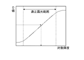
被写体の輝度分布が適正露光範囲内にあれば明瞭な明るさ分布の画像となる。一方,被写体の輝度分布が適正露光範囲外(明るすぎる,暗すぎる)であれば画像は不鮮明となる。図1は、被写体の輝度(対数)とカメラの映像出力である画像濃度Dとの関係を示すグラフの一例を示す図である。
(Utilization of image information of multiple captured images captured under multiple exposure conditions)
If the luminance distribution of the subject is within the proper exposure range, the image has a clear brightness distribution. On the other hand, if the luminance distribution of the subject is outside the appropriate exposure range (too bright or too dark), the image will be unclear. FIG. 1 is a diagram showing an example of a graph showing the relationship between the luminance (logarithm) of a subject and the image density D that is the video output of the camera.
画面内の所定位置の被写体輝度は、その露光条件(絞りの面積Aと露光時間T)における受光素子の濃度−輝度特性(図1に示すグラフのガンマ特性)により求まる。一方、露光条件A×T=一定の場合、同一輝度の被写体は同一画像濃度となる。したがって、比例定数をKとすれば、式(1)が成立する。
D=≒K/(A・T)・・・式(1)
The subject luminance at a predetermined position in the screen is obtained from the density-luminance characteristic (gamma characteristic of the graph shown in FIG. 1) of the light receiving element under the exposure conditions (aperture area A and exposure time T). On the other hand, when the exposure condition A × T = constant, subjects with the same brightness have the same image density. Therefore, if the proportionality constant is K, equation (1) is established.
D = ≈K / (A · T) Expression (1)
そして、所定の露光条件(A・T)における輝度Bと濃度Dの関係(ガンマ特性)が既知であれば、異なる露光条件下における濃度D*における被写体輝度B*は、まずガンマ特性から被写体輝度を補正し、更に式(1)により露光条件による輝度倍率を求めることにより算出することができる。したがって、輝度測定対象となる被写体の露光条件はガンマ特性の中央に位置させるようにすることが望ましい。 If the relationship (gamma characteristic) between the luminance B and the density D under a predetermined exposure condition (A / T) is known, the object luminance B * at the density D * under different exposure conditions is first calculated from the gamma characteristic. Can be calculated by further calculating the luminance magnification according to the exposure condition according to equation (1). Therefore, it is desirable that the exposure condition of the subject whose luminance is to be measured is positioned at the center of the gamma characteristic.
詳細は、後述するが、発光体等として車両前方に存在する物体の輝度は、その物体の属性によっておおよそ推定できる。そこで、物体の属性ごとに推定される輝度を考慮して、その輝度に応じた複数の露光条件で撮像することで、各露光条件に適した発光体等をそれ以外の発光体等などと判別しやすくなる。例えば、発光体がハイビームで走行中の対向車の場合、露光条件として露光量を小さくすることで、撮像画像においてハイビームを照射するヘッドランプは写るものの、路面やテールランプなどの比較的輝度が低い発光体や光反射体は写りにくくなる。そのため、露光量が小さい露光条件で撮像した撮像画像の画像情報を解析することで、物体の属性としてハイビームを照射するヘッドランプの識別が容易となる。同様に異なる露光条件で撮像した撮像画像の画像情報を解析することで、種々の物体の属性を判別することが可能となる。 Although details will be described later, the luminance of an object existing in front of the vehicle as a light emitter or the like can be roughly estimated by the attribute of the object. Therefore, taking into account the luminance estimated for each attribute of the object, imaging is performed under a plurality of exposure conditions according to the luminance, so that a light emitter suitable for each exposure condition is distinguished from other light emitters, etc. It becomes easy to do. For example, in the case of an oncoming vehicle running with a high beam, the headlamp that irradiates the high beam in the captured image appears in the captured image by reducing the exposure amount as an exposure condition, but it emits light with relatively low brightness such as the road surface and tail lamp. The body and light reflectors are difficult to see. Therefore, by analyzing image information of a captured image captured under an exposure condition with a small exposure amount, it becomes easy to identify a headlamp that emits a high beam as an object attribute. Similarly, by analyzing image information of captured images captured under different exposure conditions, it is possible to determine the attributes of various objects.
(オプティカルフローの活用)
画像センサ(カメラ)と路上物体の相対位置関係が変化する場合、連続した撮像画像において物体の像は流れる。このような現象をオプティカルフロー(以下、適宜「OF」と称する)という。OFは、自車両と物体との相対距離が近いほど、また、相対速度差が大きいほど、大きくなる。例えば、自車両が停車中の場合、移動物体に応じたOFが発生する。また、自車両が走行中の場合、道路照明やデリニエータ等の路上固定物に応じたOFが発生するとともに、自車両と速度の異なる前方車に応じたOFが発生する。そこで、OFの大きさに基づいて自車両前方の物体の属性が道路に対する移動物体か固定物かを判別することができる。
(Utilization of optical flow)
When the relative positional relationship between the image sensor (camera) and the object on the road changes, the image of the object flows in consecutive captured images. Such a phenomenon is referred to as an optical flow (hereinafter referred to as “OF” as appropriate). The OF increases as the relative distance between the host vehicle and the object is shorter and the relative speed difference is larger. For example, when the host vehicle is stopped, OF corresponding to the moving object is generated. In addition, when the host vehicle is traveling, an OF is generated according to a fixed object on the road such as road illumination or a delineator, and an OF is generated according to a preceding vehicle having a speed different from that of the host vehicle. Therefore, it is possible to determine whether the attribute of the object ahead of the host vehicle is a moving object or a fixed object with respect to the road based on the size of the OF.
(道路消失点の活用)
図2は、高速道路の直線路における消失点とオプティカルフローの関係を模式的に示した図である。図2に示すように、直線路においては消失点が存在する。ここで、消失点とは、絵画の遠近法における収束点として定義することができる。消失点は、レーンマーク、路側帯、中央分離帯、規則的な配置で設置された道路附属施設(道路照明、デリニエータ)等の無限遠点となる。なお、道路形状(例えばカーブ)や前方車の存在などで無限遠点が求められない場合、それらの物体の近景における配置を無限遠まで延長し、それらの交点を画面上で推測することにより仮の消失点とすることも可能である。なお、消失点は
曲路(左右カーブだけではなく、道路のアップダウン)では算出することが困難であるが、左右方向の屈折路では算出可能である。また、自車両が車線変更などで道路の幅方向に移動する場合、それに伴って消失点も移動する。
(Utilization of road vanishing points)
FIG. 2 is a diagram schematically showing the relationship between the vanishing point and the optical flow on the straight road on the expressway. As shown in FIG. 2, a vanishing point exists on a straight road. Here, the vanishing point can be defined as a convergence point in the perspective of painting. The vanishing point is an infinite point such as a lane mark, a roadside zone, a median strip, or a road facility (road lighting, delineator) installed in a regular arrangement. If the infinity point cannot be obtained due to the road shape (for example, a curve) or the presence of a forward vehicle, the disposition of these objects in the foreground is extended to infinity and the intersection point is estimated on the screen. The vanishing point can also be used. The vanishing point is difficult to calculate on a curved road (not only a left / right curve but also an up / down road), but can be calculated on a left / right refraction path. Further, when the host vehicle moves in the width direction of the road due to a lane change or the like, the vanishing point moves accordingly.
(道路区域の設定と交点列の活用)
車両前方のレーンマーク、路側帯、中央分離帯などの画像データを解析することで、自車線や対向車線等の道路区域を決定できる。道路照明やデリニエータ等の道路附属施設は道路上に規則的に設置されているため、道路区域が決定されることで、夜間において発光体等がどのような物体かがより精度良く判別できる。具体的には、夜間において発光体等の光輝点や光点列が道路区域に対してどの位置(例えば、自車線か対向車線か路肩か)に存在するか、および前述のOFがどうなっているか、を考慮することで発光体等の属性が道路照明か、デリニエータか、先行車か、対向車かが判別可能となる。
(Road area setting and intersection sequence)
By analyzing image data such as lane marks, roadside zones, and median strips in front of the vehicle, road areas such as the own lane and the oncoming lane can be determined. Since road ancillary facilities such as road lighting and a delineator are regularly installed on the road, the road area is determined, so that it is possible to more accurately determine what kind of object is a light emitter or the like at night. Specifically, at night, the position of a bright spot such as a illuminant or a light spot sequence with respect to a road area (for example, own lane, oncoming lane, or shoulder), and the above-mentioned OF. It is possible to determine whether the attribute of the light emitter or the like is road illumination, delineator, preceding vehicle, or oncoming vehicle.
以下、図面を参照しながら、本発明を実施するための最良の形態について詳細に説明する。なお、図面の説明において同一の要素には同一の符号を付し、重複する説明を適宜省略する。 Hereinafter, the best mode for carrying out the present invention will be described in detail with reference to the drawings. In the description of the drawings, the same elements are denoted by the same reference numerals, and repeated descriptions are omitted as appropriate.
図3は、本実施の形態に係る車両用前照灯装置を適用した車両の外観を示す概略図である。図3に示すように、本実施の形態に係る車両10は、前照灯装置12と、前照灯装置12による光の照射を制御する前照灯制御装置としての制御システム14と、車両10の走行状況を示す情報を検出してその検出信号を制御システム14へ出力する各種センサと、車両前方を監視する前方監視カメラ16と、GPS衛星からの軌道信号や車車間通信の信号などを受信して制御システム14へ出力するアンテナ18と、を備える。
FIG. 3 is a schematic diagram showing the appearance of a vehicle to which the vehicle headlamp device according to the present embodiment is applied. As shown in FIG. 3, the
各種センサとしては、例えば、ステアリングホイール20の操舵角を検出するステアリングセンサ22と、車両10の車速を検出する車速センサ24と、自車両の周囲の照度を検出する照度センサ26とが設けられており、これらのセンサ22,24,26が前述の制御システム14に接続されている。
As various sensors, for example, a
本発明に適用できる前照灯装置としては、照射する光の配光を前方に存在する物体の属性に応じて変化させることができる構成であれば特に限定されない。例えば、ハロゲンランプやガスディスチャージヘッドランプ、LEDを用いたヘッドランプを採用することができる。本実施の形態では、ハイビーム領域の配光を変化させることができる多灯式の方式(複数のLEDなどで構成)を例として説明するが、ランプをスイブルできる方式を採用することも可能である。 The headlamp device applicable to the present invention is not particularly limited as long as it can change the light distribution of the irradiated light according to the attribute of the object existing in front. For example, a halogen lamp, a gas discharge headlamp, or a headlamp using an LED can be employed. In the present embodiment, a multi-lamp system (configured by a plurality of LEDs) capable of changing the light distribution in the high beam region will be described as an example, but a system capable of swiveling the lamp may be employed. .
前照灯装置12は、左右一対の前照灯ユニット12R,12Lを有する。前照灯ユニット12R,12Lは、内部構造が左右対称であるほかは互いに同じ構成であり、右側のランプハウジング内にロービーム用灯具ユニット28Rおよびハイビーム用灯具ユニット30Rが、左側のランプハウジング内にロービーム用灯具ユニット28Lおよびハイビーム用灯具ユニット30Lがそれぞれ配置されている。
The
制御システム14は、入力された各種センサの各出力に基づいて車両の前部の左右にそれぞれ装備された、ハイビーム領域の配光を変化させることができる前照灯ユニット12R,12L、すなわち複数のLEDの点消灯をそれぞれ制御してその配光特性を変化することが可能な前照灯装置12を制御する。この種のADB(Adaptive Driving Beam)によれば、車両前方に存在する物体の属性(先行車、対向車、道路照明など)に応じて、前方車にグレアを与えることなく、前方の視認性を向上することができ、走行安全性を高める上で有効である。
The
(車両用前照灯装置)
次に、本実施の形態に係る車両用前照灯装置について説明する。図4は、本実施の形態に係る車両用前照灯装置110の概略構成を示すブロック図である。車両用前照灯装置110は、前照灯ユニット12R,12Lと、前照灯ユニット12R,12Lによる光の照射を制御する制御システム14とを備える。そして、車両用前照灯装置110は、制御システム14において車両前方に存在する物体の属性を判別し、その物体の属性に基づいて配光制御条件を決定し、決定された配光制御条件に基づいて前照灯ユニット12R,12Lによる光の照射を制御する。
(Vehicle headlamp device)
Next, the vehicle headlamp device according to the present embodiment will be described. FIG. 4 is a block diagram showing a schematic configuration of the
そこで、本実施の形態に係る制御システム14には、ドライバの視対象を含む車両前方の撮像画像を取得するための前方監視カメラ16が接続されている。また、車両の走行状態を判断する際に参照される、操舵情報や車速を検出するためのステアリングセンサ22や車速センサ24、照度センサ26が接続されている。照度センサ26としては、例えば、対向車や人工光源(道路照明や店舗照明)から受けた光の鉛直面照度(人工光源によるグレア量)を計測できるように受光面を鉛直に設置したものや、走行環境や車両上方から受けた光の水平面照度を計測できるように受光面を水平に設置したものが用いられる。
Therefore, the
(制御システム)
図4に示すように、制御システム14は、画像処理ECU32と、配光制御ECU34と、GPSナビゲーションECU36と、車車間通信ECU37と、車内LAN制御ECU38とを備える。各種ECUおよび各種車載センサは、車内LANバス40により接続されデータの送受信が可能になっている。画像処理装置としての画像処理ECU32は、前方監視カメラ16により取得された、車両前方を複数の露光条件で撮像した複数の撮像画像の画像情報(画像データ)や、各種車載センサに基づいて前方に存在する物体の属性を判別する。なお、画像処理ECU32内部は各部が高速バス42で接続されている。配光制御ECU34は、画像処理ECU32および各種車載センサの情報に基づいて、車両が置かれている走行環境に適した配光制御条件を決定し、その制御信号を前照灯ユニット12R,12Lに出力する。
(Control system)
As shown in FIG. 4, the
前照灯ユニット12R,12Lは、配光制御ECU34から出力された制御信号が光学部品の駆動装置や光源の点灯制御回路に入力されることで、配光が制御される。前方監視カメラ16は、CCDやCMOSなどの画像センサを備えた単眼カメラであり、その画像データから運転に必要な道路線形情報、道路附属施設、対向車・先行車の存在状況や位置の情報などを、必要であれば他のレーダセンサなどと協調して取得する。
The
図5は、本実施の形態に係る物体属性判別処理を含む配光制御方法を示すフローチャートである。物体属性の判別は、主に図4に示す画像処理ECU32で実行され、配光制御は、主に配光制御ECU34で実行される。
FIG. 5 is a flowchart showing a light distribution control method including object attribute discrimination processing according to the present embodiment. The discrimination of the object attribute is mainly executed by the
所定のタイミングで処理が開始されると、各種車載センサ(ステアリングセンサ22、車速センサ24、照度センサ26)、GPSナビゲーションECU36、車車間通信ECU37などから出力されたデータが車内LANバス40を介して外部データ入力手段44で取得される(S10)。また、前方監視カメラ16によって複数の露光条件で撮像した複数の撮像画像の画像データが画像データ取得手段46で取得される(S12)。なお、前方監視カメラ16から出力される画像データは、モノクロ画像に対応していてもよいしカラー画像に対応していてもよい。
When processing is started at a predetermined timing, data output from various in-vehicle sensors (the
取得された各画像データは、画像データ蓄積手段48においてRAMなどの記憶手段に一時的に記憶される(S14)。画像解析手段50は、画像データに含まれている濃度データに対して差分や微分、さらにはSOBEL演算を施すことにより周辺と濃度の異なる物体(例えば、ヘッドライト、テールランプ、道路照明などの発光体や、路面、レーンマーク、デリニエータなどの光反射体)の輪郭を抽出する、エッジ処理を行う(S18)。なお、エッジ処理の方法はこれらに限られず、公知の方法を適宜変形させて用いてもよい。 Each acquired image data is temporarily stored in storage means such as RAM in the image data storage means 48 (S14). The image analysis means 50 performs a difference or differentiation on the density data included in the image data, and further an object having a density different from that of the surroundings by performing a SOBEL operation (for example, a light emitter such as a headlight, a tail lamp, and road illumination). In addition, edge processing is performed to extract the contour of a road surface, a lane mark, and a light reflector such as a delineator (S18). Note that the edge processing method is not limited thereto, and a known method may be appropriately modified and used.
次に、濃度輝度変換手段52において画像の濃度データが輝度(明るさ)データに変換される(S20)。画像データの輝度への変換は、露光条件(撮像条件)下における画像濃度と車両前方の範囲の輝度との関係を求めておけば、露光条件を勘案して求めることができる(図1参照)。 Next, the density / luminance conversion means 52 converts the density data of the image into luminance (brightness) data (S20). The conversion of the image data into luminance can be obtained in consideration of the exposure condition if the relationship between the image density under the exposure condition (imaging condition) and the luminance in the range in front of the vehicle is obtained (see FIG. 1). .
次に、異なる露光条件で撮像された撮像画像の画像データごとに、光輝物体、例えば発光体や光反射体の位置を検出する。具体的には、光輝物体検出手段54は、S20の処理における濃度輝度変換で所定の輝度(例えば、路面やレーンマークに対応する輝度)以上、または、所定の範囲の輝度、の物体を光輝物体として抽出し、その位置を検出する(S28)。
Next, the position of a bright object, for example, a light emitter or a light reflector, is detected for each image data of a captured image captured under different exposure conditions. Specifically, the bright
次に、動画のように時系列で連続的に取得される画像データの解析により光輝物体のOFを判定する。はじめに、前回の画像解析処理において内部メモリ56に記憶された光輝物体の位置や物体の候補などの画像特性のデータと、現在の画像特性のデータとがOF算出手段58により取得される(S30)。
Next, the OF of the bright object is determined by analyzing image data that is continuously acquired in time series like a moving image. First, the OF calculation means 58 acquires image characteristic data such as the position of a bright object and object candidates stored in the
OF算出手段58は、異なる時間に取得した複数の撮像画像の画像特性データに基づいて、各光輝物体にOFが発生しているか否かを検出する(S32)。具体的には、OF算出手段58は、取得した車両前方の撮像画像の輝度データに基づいて、発光体又は光反射体として車両前方に存在する光輝物体のOFを算出する。そして、物体属性判別手段60は、複数の露光条件で撮像された撮像画像の各画像データや、OF算出手段58により算出されたOFに基づいて、発光体又は光反射体として車両前方に存在する物体の属性を判別する(S34)。なお、ステップS34における物体属性判別方法については後述する。
The OF calculation means 58 detects whether OF has occurred in each bright object based on the image characteristic data of a plurality of captured images acquired at different times (S32). Specifically, the OF
物体の属性が判別されると、現在の画像特性データが内部メモリ56に記憶される(S36)。具体的には、OF検出のために必要な光輝物体の位置、属性、OFのベクトルなどである。このデータは次回の画像処理におけるOFの算出に用いられる。 When the attribute of the object is determined, the current image characteristic data is stored in the internal memory 56 (S36). Specifically, the position and attribute of the bright object necessary for the OF detection, the OF vector, and the like. This data is used for calculation of OF in the next image processing.
物体属性判別手段60により判別された各物体の属性データや道路形状などのデータが内部データ出力手段62から出力される(S38)。出力されたデータは車内LANバス40を介して配光制御ECU34に入力され、そのデータに含まれる物体の属性や自車両の走行状態、天候条件などに基づいて配光制御条件が決定される(S40)。そして、配光制御ECU34は、決定された配光制御条件に基づいて前照灯ユニット12R,12L内に設けられている光源や駆動源へ制御信号を出力し配光を制御する(S42)。
The attribute data and road shape data of each object determined by the object attribute determining means 60 are output from the internal data output means 62 (S38). The output data is input to the light
(物体属性判別方法)
次に、物体属性判別処理を行うステップS34について詳述する。道路上を走行中の車両の前方には様々な物体が存在する。そのような状況下において夜間を走行中の車両の前方監視カメラ16が光輝物体として識別する物体としては、以下のものがある。
(Object attribute discrimination method)
Next, step S34 for performing object attribute discrimination processing will be described in detail. There are various objects in front of a vehicle traveling on a road. Under such circumstances, there are the following objects that the
はじめに、夜間において走行中の対向車のHL(ヘッドライト)、先行車のTL(テールライト)が挙げられる。このようなライトは通常左右一対のペアライトとして存在するとともに、水平線より下方に位置する。また、OFの大きさは物体が先行車の場合に小さくなり、対向車の場合に大きくなる。 First, HL (headlight) of an oncoming vehicle traveling at night and TL (taillight) of a preceding vehicle may be mentioned. Such lights usually exist as a pair of left and right pair lights and are positioned below the horizontal line. In addition, the size of OF decreases when the object is a preceding vehicle, and increases when the object is an oncoming vehicle.
次に、道路照明やデリニエータが挙げられる。これらの固定物は、通常設置基準が規定されており、例えば道路照明は路面より5m以上、つまり水平線より上方に存在する。一方、デリニエータは、ガードレール上端部に設置されており、水平線より下方に存在する。また、OFの大きさは物体が固定物であれば自車両の車速および物体と自車両との距離に応じた値となる。 Next, there are road lighting and delineators. For these fixed objects, a normal installation standard is defined. For example, road illumination exists 5 m or more from the road surface, that is, above the horizon. On the other hand, the delineator is installed at the upper end of the guardrail and is present below the horizontal line. Further, if the object is a fixed object, the size of OF is a value corresponding to the vehicle speed of the host vehicle and the distance between the object and the host vehicle.
上述の物体以外にも、店舗照明、広告ネオンサイン、カーブサインなどが光輝物体として検出されうる。店舗照明や広告ネオンサインは、ランダムに存在する固定物体であり、道路照明やデリニエータのように配置されている位置に規則性がないため、この点を考慮した画像解析をすることで道路照明等の固定物と判別することができる。また、カーブサインは、その設置位置がデリニエータとほぼ同じ高さであるためデリニエータとの弁別は困難であるが、カーブサインをデリニエータと誤認しても配光制御に与える影響はないため、画像解析において特段の考慮は必要とされない。 In addition to the objects described above, store lighting, advertisement neon signs, curve signs, and the like can be detected as bright objects. Store lighting and advertising neon signs are fixed objects that exist at random, and there is no regularity in the positions of road lights and delineators, so road lighting etc. Can be identified as a fixed object. In addition, it is difficult to discriminate the curve sign from the delineator because the installation position is almost the same height as the delineator. However, misidentification of the curve sign as a delineator has no effect on the light distribution control. However, no special consideration is required.
本実施の形態に係る物体判別方法は、以上のような物体の存在を前提に行われる。図6は、物体属性判別処理に用いる複数の撮像画像の露光条件を説明するための模式図である。横軸は経過時間Tであり,縦軸は絞りの面積Aである。なお、図6に示す、各撮像画像に対応する長方形のブロックの横軸や縦軸の比率は、必ずしも実際の条件を正確に表しているとは限らず、定性的な説明を可能とする程度に設定されている。 The object discrimination method according to the present embodiment is performed on the premise of the existence of the object as described above. FIG. 6 is a schematic diagram for explaining the exposure conditions of a plurality of captured images used for the object attribute discrimination process. The horizontal axis is the elapsed time T, and the vertical axis is the aperture area A. Note that the ratio of the horizontal axis and the vertical axis of the rectangular block corresponding to each captured image shown in FIG. 6 does not necessarily accurately represent the actual condition, but allows qualitative explanation. Is set to
ある露光条件で車両前方を撮像した場合、物体の明るさや色によって撮像画像中での物体の写り方が異なる。また、異なる露光条件で車両前方を撮像すると、同じ物体であっても撮像画像中での写り方が異なることが普通である。 When the front of the vehicle is imaged under certain exposure conditions, the way the object appears in the captured image differs depending on the brightness and color of the object. Further, when the front of the vehicle is imaged under different exposure conditions, the way the image is captured in the captured image is usually different even for the same object.
本実施の形態では、前方監視カメラ16としてカラーカメラを使用している。前方監視カメラ16は、所定の期間において露光量が異なる複数の露光条件で車両前方を撮像し、撮像した複数の撮像画像の画像情報を物体属性判別手段60へ出力する。ここで、露光量は、物体が発光体又は光反射体として車両前方に存在する場合に想定される輝度に基づいて物体の属性ごとに設定されていている。これにより、物体の属性の判別精度がより向上する。
In the present embodiment, a color camera is used as the
以下では、所定の1サイクル内に露光量が異なる5つの露光条件で6個の前方視野画像を取得した例について説明する。これにより、5つの視対象の輝度測定を達成しようとしている。それら5個の測定視対象の平均的な輝度は下記の通りである。例えば、路面≒1cd/m2、テールランプ≒200cd/m2、道路照明≒2000cd/m2、Loビーム≒70000cd/m2、Hiビーム≒7000000cd/m2である。 Hereinafter, an example in which six front-view images are acquired under five exposure conditions with different exposure amounts within a predetermined cycle will be described. Thereby, it is going to achieve the brightness | luminance measurement of five visual objects. The average luminance of these five objects to be measured is as follows. For example, road ≒ 1 cd / m 2, a tail lamp ≒ 200 cd / m 2, road lighting ≒ 2000cd / m 2, Lo beam ≒ 70000cd / m 2, Hi beam ≒ 7000000cd / m 2.
そこで、1サイクル内の各露光条件(絞りの面積A、露光時間T)は下記の式(2)を満たすように設定されている。
測定対象輝度×(A×T)≒一定・・・式(2)
Therefore, each exposure condition (aperture area A, exposure time T) within one cycle is set to satisfy the following expression (2).
Brightness to be measured x (A x T) ≒ constant (2)
つまり、各視対象の推定輝度と、露光量(≒A×T:図6に示す各ブロックの面積に相当)との積が一定となるように、露光条件が設定されている。このように、撮像画像において、適正な露光範囲にある視対象(物体)は明瞭な光点として検出される。そこで、物体属性判別手段60は、露光量の異なる複数の露光条件で撮像した複数の撮像画像の画像テータに基づいて物体の属性を判別する。 That is, the exposure conditions are set so that the product of the estimated luminance of each visual target and the exposure amount (≈A × T: equivalent to the area of each block shown in FIG. 6) is constant. Thus, in the captured image, a visual target (object) in an appropriate exposure range is detected as a clear light spot. Therefore, the object attribute determination unit 60 determines the attribute of the object based on the image data of a plurality of captured images captured under a plurality of exposure conditions with different exposure amounts.
例えば、路面の輝度に応じた露光量で撮影した画像P1においては、路面は明瞭に写るものの、テールランプ、道路照明、ヘッドランプなどの発光体は露光がオーバーなため明瞭には写らない。また、テールランプの輝度に応じた露光量で撮影した画像P2、P3においては、テールランプは明瞭に写るものの、路面は露光がアンダーなため写らず、道路照明やヘッドランプは露光がオーバーなため明瞭には写らない。また、道路照明の輝度に応じた露光量で撮影した画像P4においては、道路照明は明瞭に写るものの、路面やテールランプは露光がアンダーなため写らず、ヘッドランプは露光がオーバーなため明瞭には写らない。また、ロービーム状態のヘッドランプの輝度に応じた露光量で撮影した画像P5においては、ロービーム状態のヘッドランプは明瞭に写るものの、路面、テールランプ、道路照明は露光がアンダーなため写らず、ハイビーム状態のヘッドランプは露光がオーバーなため明瞭には写らない。また、ハイビーム状態のヘッドランプの輝度に応じた露光量で撮影した画像P6においては、ハイビーム状態のヘッドランプは明瞭に写るものの、路面、テールランプ、道路照明、ロービーム状態のヘッドランプは露光がアンダーなため写らない。このように、画像処理ECU32は、複数の露光条件で撮像された撮像画像の画像データを処理することで、物体の属性を精度良く判別できる。
For example, in the image P1 photographed with an exposure amount corresponding to the luminance of the road surface, the road surface is clearly visible, but light emitters such as tail lamps, road lighting, and headlamps are not clearly visible because they are overexposed. Also, in the images P2 and P3 taken with the exposure amount according to the brightness of the tail lamp, the tail lamp is clearly visible, but the road surface is not exposed because it is underexposed, and the road illumination and headlamp are clearly overexposed. Is not shown. In addition, in the image P4 taken with the exposure amount corresponding to the brightness of the road illumination, although the road illumination is clearly shown, the road surface and the tail lamp are not shown because the exposure is underexposed, and the headlamp is overexposed because it is overexposed. I don't see it. In addition, in the image P5 taken with the exposure amount corresponding to the brightness of the headlamp in the low beam state, the headlamp in the low beam state is clearly visible, but the road surface, the tail lamp, and the road illumination are not exposed because the exposure is under, and the high beam state This headlamp is overexposed and is not clearly visible. In addition, in the image P6 taken with the exposure amount corresponding to the brightness of the headlamp in the high beam state, the headlamp in the high beam state is clearly visible, but the road surface, the tail lamp, the road illumination, and the headlamp in the low beam state are underexposed. I don't see it. Thus, the
なお、本実施の形態に係る画像処理ECU32は、異なるタイミングで撮像された複数の撮像画像の画像情報に基づいて、物体のオプティカルフローを算出するOF算出手段58を更に備えている。OF算出手段58は、オプティカルフローに基づいて物体の属性を判別している。そこで、オプティカルフローに基づいた物体の属性判別結果を、前述の物体の属性判別に加味することで、物体が移動体か固定物か、移動体であれば先行車であるか対向車であるかなど、より広範囲な物体の属性の判別精度が向上する。
Note that the
また、画像処理ECU32は、物体が自車両に向けて発する光のグレア照度を、画像情報と露光条件とに基づいて算出する照度算出部を更に備えてもよい。これにより、グレア照度をより正確に算出できる。グレア照度は、光輝物体の輝度を画像データにおける画像濃度と露光条件から逆算するとともに、その輝度と光輝物体の推定面積から算出される。算出されたグレア照度が許容グレア照度を上回った場合、画像処理ECU32は、対象となる光輝物体周辺を通常より明るく照らすように前照灯装置12を制御すべく、配光制御ECU34に制御信号を送信する。これにより、ドライバが光輝物体から受けるグレアが緩和される。なお、照度算出部は、車車間通信ECU37によって取得した対向車のヘッドランプ情報に基づいてグレア照度を算出してもよい。これにより、ドライバが光輝物体である対向車から受けるグレアがより確実に緩和される。
The
なお、上述の物体判別処理において、GPSナビゲーションECU36から取得した現在走行している道路の特性情報(高速道路などの道路種別、車線数、市街地か郊外か、など)や、車車間通信ECU37から取得した前方車の情報(例えば、ハイビームまたはロービームのいずれの状態か、灯具の種類、ランプ面積、車種など)を加味することで、前方車、店舗照明、広告ネオンサイン、カーブサインなどの判別精度が向上する。
In the object discrimination process described above, the characteristic information (such as the type of road such as an expressway, the number of lanes, whether it is an urban area or a suburb, etc.) acquired from the
また、光輝物体の色の判別が可能なカラーカメラである前方監視カメラ16は、センサの光輝物体の位置に対応するR(赤)素子とB(青)素子の出力比を算出することで、ノイズ光の多い市街地における先行車、対向車、交通信号、道路照明、店舗照明などの判別がしやすくなる。
Further, the
また、画像データのうち、テールライトTL(先行車、赤色)の位置に対応するセンサのR素子とB素子の出力比R/B(TL)と、ヘッドライトHL(対向車、白色)の位置に対応するセンサR素子とB素子の出力比R/B(HL)とを比較すると、R/B(TL)>>R/B(HL)の関係がある。そこで、各色の光に対するR/Bを実験やシミュレーションで事前に求めておくことで、先行車と対向車との判別精度の向上が可能となる。特に、先行車と対向車の位置が交錯しやすい曲路においての判別精度の向上に寄与する。 In the image data, the output ratio R / B (TL) of the R element and B element of the sensor corresponding to the position of the taillight TL (leading vehicle, red), and the position of the headlight HL (oncoming vehicle, white) When the output ratio R / B (HL) of the sensor R element and the B element corresponding to is compared, there is a relationship of R / B (TL) >> R / B (HL). Therefore, by determining the R / B for each color light in advance through experiments and simulations, it is possible to improve the discrimination accuracy between the preceding vehicle and the oncoming vehicle. In particular, this contributes to an improvement in discrimination accuracy on a curved road where the positions of the preceding vehicle and the oncoming vehicle easily cross.
具体的には、前方監視カメラ16は、第1の撮像画像(図6に示す画像P2)をR信号の画像情報として出力し、第1の撮像画像と異なるタイミングで撮像した第2の撮像画像(図6に示す画像P3)をB信号の画像情報として出力する。物体属性判別手段60は、R信号の画像情報とB信号の画像情報とに基づいて物体が先行車であるか判別する。これにより、例えば、テールランプとその他の光輝物体との判別がより精度良く可能となる。また、前方監視カメラ16は、第1の撮像画像(画像P2)と第2の撮像画像(画像P3)とを連続して撮像している。これにより、第1の撮像画像および第2の撮像画像において、同一の先行車のテールランプの位置のずれが抑制され、画像処理ECU32における正確な出力比の判定が可能となる。
Specifically, the
上述したように、本実施の形態に係る制御システム14は、取得した撮像画像に基づいて物体を判別することができるため、夜間走行においてドライバに特段の操作負担をかけることなく物体の属性に応じた適切な配光制御が可能となる。配光制御ECU34は、画像処理ECU32から取得したデータに基づいて、例えば、車両前方に光輝物体が存在していないと判断する場合には、自動的に前照灯ユニットの配光をハイビームにする配光制御が可能である。また、画像処理ECU32は、光輝物体として対向車や先行車が存在していると判断する場合には、自動的に前照灯ユニットの配光を対向車や先行車にグレアを与えない配光(対向車や先行車が存在する領域を照らすLEDを消灯または暗くした配光)へと変化させる制御が可能となる。
As described above, since the
また、配光制御ECU34は、従来では対向車や先行車と判別できなかった道路照明やデリニエータしか存在しないと判断した場合には、前照灯ユニットの配光をハイビームの状態に維持することで、前照灯ユニットの照明能力をより有効に活用することができる。
Also, if the light
また、物体属性判別手段60は、物体のOFから推定される自車両と物体との相対速度V1と、自車両速度V2とを比較することでその物体の属性を判別することができるため、物体の属性を更に詳細に判別することができるため、より適切な配光制御が可能となる。 The object attribute determining means 60 can determine the attribute of the object by comparing the relative speed V1 between the host vehicle and the object estimated from the OF of the object and the host vehicle speed V2. Therefore, more appropriate light distribution control can be performed.
具体的には、相対速度V1と自車両速度V2とを比較することで、物体の属性が道路に対する固定物であるか移動体であるかが判別される。これにより、物体属性判別手段60は、例えば、物体との相対速度V1がほぼ自車両速度V2とほぼ等しい場合には、その物体が道路照明やデリニエータなどの固定物であると判別し、物体との相対速度V1が自車両速度V2と異なる場合には、その物体が対向車や先行車などの移動体であると判別することができる。 Specifically, by comparing the relative speed V1 and the host vehicle speed V2, it is determined whether the attribute of the object is a fixed object or a moving object with respect to the road. Thereby, for example, when the relative speed V1 with respect to the object is substantially equal to the own vehicle speed V2, the object attribute determination means 60 determines that the object is a fixed object such as road illumination or a delineator, When the relative speed V1 of the vehicle is different from the own vehicle speed V2, it can be determined that the object is a moving body such as an oncoming vehicle or a preceding vehicle.
また、物体属性判別手段60は、物体の位置やOFが撮像画像の上下方向のどこに存在するかによって、その物体の属性が道路照明であるかデリニエータであるかを判別することができる。 Further, the object attribute determination means 60 can determine whether the attribute of the object is road illumination or a delineator depending on the position of the object or where the OF is in the vertical direction of the captured image.
本実施の形態に係る前照灯制御装置としての制御システム14およびそれを備えた車両用前照灯装置110によれば、特に夜間の交通視環境(照明状況、対向車状況)に応じて詳細な配光制御が可能となり、交通事故防止に貢献できる。また、本実施の形態に係る制御システム14は、複数のカメラを用いたり複雑な機構のカメラを用いたりせずに、単眼カメラを用いることで光輝物体の属性を判別することができるため、システム全体のコストの低減が可能となる。
According to the
また、前方監視カメラ16は、昼間においては、所定時間内においてほぼ同一の露光条件で画像を取得する。夜間のように、発光体や光反射体の輝度の違いによる写りやすさの違いがないため、画像処理や制御の容易さを考慮したためである。
Further, the
以上、本発明を上述の実施の形態を参照して説明したが、本発明は上述の実施の形態に限定されるものではなく、実施の形態の構成を適宜組み合わせたものや置換したものについても本発明に含まれるものである。また、当業者の知識に基づいて実施の形態における組合せや処理の順番を適宜組み替えることや各種の設計変更等の変形を実施の形態に対して加えることも可能であり、そのような変形が加えられた実施の形態も本発明の範囲に含まれうる。 As described above, the present invention has been described with reference to the above-described embodiment. However, the present invention is not limited to the above-described embodiment, and the present invention can be appropriately combined or replaced with the configuration of the embodiment. It is included in the present invention. In addition, it is possible to appropriately change the combination and processing order in the embodiment based on the knowledge of those skilled in the art and to add various modifications such as various design changes to the embodiment. The described embodiments can also be included in the scope of the present invention.
12 前照灯装置、 14 制御システム、 16 前方監視カメラ、 26 照度センサ、 30L,30R ハイビーム用灯具ユニット、 32 画像処理ECU、 34 配光制御ECU、 37 車車間通信ECU、 44 外部データ入力手段、 50 画像解析手段、 52 濃度輝度変換手段、 54 光輝物体検出手段、 58 OF算出手段、 60 物体属性判別手段、 110 車両用前照灯装置。
DESCRIPTION OF
Claims (5)
前記撮像部は、所定の期間において露光量が異なる複数の露光条件で車両前方を撮像し、撮像した複数の撮像画像の画像情報を前記属性判別部へ出力し、
前記露光量は、物体が発光体又は光反射体として車両前方に存在する場合に想定される輝度に基づいて物体の属性ごとに設定されていることを特徴とする請求項1に記載の画像処理装置。 An imaging unit for imaging the front of the vehicle;
The imaging unit images the front of the vehicle under a plurality of exposure conditions having different exposure amounts in a predetermined period, and outputs image information of the plurality of captured images to the attribute determination unit,
The image processing according to claim 1, wherein the exposure amount is set for each attribute of the object based on a luminance assumed when the object exists in front of the vehicle as a light emitter or a light reflector. apparatus.
前記属性判別部は、前記オプティカルフローに基づいて前記物体の属性を判別することを特徴とする請求項1乃至3のいずれか1項に記載の画像処理装置。 An optical flow calculation unit that calculates an optical flow of the object based on image information of a plurality of captured images captured at different timings;
The image processing apparatus according to claim 1, wherein the attribute determination unit determines an attribute of the object based on the optical flow.
前記属性判別部は、前記R信号の画像情報と前記B信号の画像情報とに基づいて前記物体が先行車であるか判別することを特徴とする請求項2に記載の画像処理装置。 The imaging unit outputs a first captured image as image information of an R signal, outputs a second captured image captured at a timing different from that of the first captured image, as image information of a B signal,
The image processing apparatus according to claim 2, wherein the attribute determination unit determines whether the object is a preceding vehicle based on image information of the R signal and image information of the B signal.
Priority Applications (2)
| Application Number | Priority Date | Filing Date | Title |
|---|---|---|---|
| JP2011111724A JP2012240530A (en) | 2011-05-18 | 2011-05-18 | Image processing apparatus |
| EP12168151A EP2525302A1 (en) | 2011-05-18 | 2012-05-16 | Image processing system |
Applications Claiming Priority (1)
| Application Number | Priority Date | Filing Date | Title |
|---|---|---|---|
| JP2011111724A JP2012240530A (en) | 2011-05-18 | 2011-05-18 | Image processing apparatus |
Publications (1)
| Publication Number | Publication Date |
|---|---|
| JP2012240530A true JP2012240530A (en) | 2012-12-10 |
Family
ID=46507847
Family Applications (1)
| Application Number | Title | Priority Date | Filing Date |
|---|---|---|---|
| JP2011111724A Pending JP2012240530A (en) | 2011-05-18 | 2011-05-18 | Image processing apparatus |
Country Status (2)
| Country | Link |
|---|---|
| EP (1) | EP2525302A1 (en) |
| JP (1) | JP2012240530A (en) |
Cited By (4)
| Publication number | Priority date | Publication date | Assignee | Title |
|---|---|---|---|---|
| JP2014146164A (en) * | 2013-01-29 | 2014-08-14 | Toyota Motor Corp | Object detection apparatus |
| JP2016066223A (en) * | 2014-09-24 | 2016-04-28 | 三洋テクノソリューションズ鳥取株式会社 | On-vehicle communication machine and roadside machine |
| JP2016167173A (en) * | 2015-03-10 | 2016-09-15 | 株式会社Jvcケンウッド | Warning device, warning method, and warning program |
| WO2018008461A1 (en) * | 2016-07-05 | 2018-01-11 | 日立オートモティブシステムズ株式会社 | Image processing device |
Families Citing this family (6)
| Publication number | Priority date | Publication date | Assignee | Title |
|---|---|---|---|---|
| US9619720B2 (en) * | 2013-08-19 | 2017-04-11 | Gentex Corporation | Vehicle imaging system and method for distinguishing between vehicle tail lights and flashing red stop lights |
| JP6218499B2 (en) * | 2013-08-23 | 2017-10-25 | スタンレー電気株式会社 | Lighting control device for vehicle headlamp, vehicle headlamp system |
| DE102015012809A1 (en) * | 2015-10-02 | 2017-04-06 | Audi Ag | Image recording device for a motor vehicle and method for operating such an image recording device |
| EP3326862A1 (en) * | 2016-11-29 | 2018-05-30 | Continental Automotive GmbH | Apparatus for automatically dealing with a glare situation caused by oncoming traffic |
| US10757320B2 (en) | 2017-12-28 | 2020-08-25 | Waymo Llc | Multiple operating modes to expand dynamic range |
| WO2019156087A1 (en) * | 2018-02-07 | 2019-08-15 | 株式会社小糸製作所 | Image processing device and vehicle light fixture |
Citations (4)
| Publication number | Priority date | Publication date | Assignee | Title |
|---|---|---|---|---|
| WO1997035743A1 (en) * | 1996-03-25 | 1997-10-02 | Donnelly Corporation | Vehicle headlight control using imaging sensor |
| JP2005092857A (en) * | 2003-08-11 | 2005-04-07 | Hitachi Ltd | Image processing system and vehicle control system |
| JP2007276766A (en) * | 2006-03-15 | 2007-10-25 | Omron Corp | Monitoring device and method, recording medium, and program |
| JP2010116036A (en) * | 2008-11-12 | 2010-05-27 | Koito Mfg Co Ltd | Headlight device for vehicle |
Family Cites Families (3)
| Publication number | Priority date | Publication date | Assignee | Title |
|---|---|---|---|---|
| WO2010050095A1 (en) * | 2008-10-31 | 2010-05-06 | 株式会社小糸製作所 | Headlamp controller |
| JP5222743B2 (en) | 2009-01-19 | 2013-06-26 | 株式会社小糸製作所 | Vehicle headlamp device |
| JP2010272067A (en) * | 2009-05-25 | 2010-12-02 | Hitachi Automotive Systems Ltd | Image processing apparatus |
-
2011
- 2011-05-18 JP JP2011111724A patent/JP2012240530A/en active Pending
-
2012
- 2012-05-16 EP EP12168151A patent/EP2525302A1/en not_active Withdrawn
Patent Citations (4)
| Publication number | Priority date | Publication date | Assignee | Title |
|---|---|---|---|---|
| WO1997035743A1 (en) * | 1996-03-25 | 1997-10-02 | Donnelly Corporation | Vehicle headlight control using imaging sensor |
| JP2005092857A (en) * | 2003-08-11 | 2005-04-07 | Hitachi Ltd | Image processing system and vehicle control system |
| JP2007276766A (en) * | 2006-03-15 | 2007-10-25 | Omron Corp | Monitoring device and method, recording medium, and program |
| JP2010116036A (en) * | 2008-11-12 | 2010-05-27 | Koito Mfg Co Ltd | Headlight device for vehicle |
Cited By (4)
| Publication number | Priority date | Publication date | Assignee | Title |
|---|---|---|---|---|
| JP2014146164A (en) * | 2013-01-29 | 2014-08-14 | Toyota Motor Corp | Object detection apparatus |
| JP2016066223A (en) * | 2014-09-24 | 2016-04-28 | 三洋テクノソリューションズ鳥取株式会社 | On-vehicle communication machine and roadside machine |
| JP2016167173A (en) * | 2015-03-10 | 2016-09-15 | 株式会社Jvcケンウッド | Warning device, warning method, and warning program |
| WO2018008461A1 (en) * | 2016-07-05 | 2018-01-11 | 日立オートモティブシステムズ株式会社 | Image processing device |
Also Published As
| Publication number | Publication date |
|---|---|
| EP2525302A1 (en) | 2012-11-21 |
Similar Documents
| Publication | Publication Date | Title |
|---|---|---|
| JP4253271B2 (en) | Image processing system and vehicle control system | |
| US11029583B2 (en) | Adjustable camera mount for a vehicle windshield | |
| JP4253275B2 (en) | Vehicle control system | |
| JP2012240530A (en) | Image processing apparatus | |
| JP4853160B2 (en) | Vehicle detection device and headlamp control device | |
| JP4544233B2 (en) | Vehicle detection device and headlamp control device | |
| JP5097648B2 (en) | Headlamp control device and vehicle headlamp device | |
| JP5409929B2 (en) | Control method for headlight device for vehicle and headlight device | |
| JP4473232B2 (en) | Vehicle front environment detecting device for vehicle and lighting device for vehicle | |
| JP5952532B2 (en) | Image processing apparatus and light distribution control method | |
| JP5313638B2 (en) | Vehicle headlamp device | |
| US20100172542A1 (en) | Bundling of driver assistance systems | |
| JP2004189229A (en) | Control system to automatically dim vehicle headlamp | |
| US9616805B2 (en) | Method and device for controlling a headlamp of a vehicle | |
| JP5361901B2 (en) | Headlight control device | |
| JP2004104646A (en) | On-vehicle image processor | |
| JP2013097885A (en) | Headlight device and headlight system | |
| US20230278485A1 (en) | Method for operating an illuminating device, and motor vehicle | |
| JP5643877B2 (en) | Vehicle headlamp device | |
| US20200361375A1 (en) | Image processing device and vehicle lamp | |
| JP7084223B2 (en) | Image processing equipment and vehicle lighting equipment | |
| WO2022244085A1 (en) | Headlight control device, headlight control system, and headlight control method | |
| WO2021039577A1 (en) | Vehicle lighting | |
| JP2013086739A (en) | Headlight control device, headlight system, and control method of headlight system |
Legal Events
| Date | Code | Title | Description |
|---|---|---|---|
| A621 | Written request for application examination |
Free format text: JAPANESE INTERMEDIATE CODE: A621 Effective date: 20140403 |
|
| A977 | Report on retrieval |
Free format text: JAPANESE INTERMEDIATE CODE: A971007 Effective date: 20150115 |
|
| A131 | Notification of reasons for refusal |
Free format text: JAPANESE INTERMEDIATE CODE: A131 Effective date: 20150203 |
|
| A02 | Decision of refusal |
Free format text: JAPANESE INTERMEDIATE CODE: A02 Effective date: 20150707 |