JP2012206572A - Vehicular brake device - Google Patents
Vehicular brake device Download PDFInfo
- Publication number
- JP2012206572A JP2012206572A JP2011072905A JP2011072905A JP2012206572A JP 2012206572 A JP2012206572 A JP 2012206572A JP 2011072905 A JP2011072905 A JP 2011072905A JP 2011072905 A JP2011072905 A JP 2011072905A JP 2012206572 A JP2012206572 A JP 2012206572A
- Authority
- JP
- Japan
- Prior art keywords
- valve
- hydraulic pressure
- solenoid valve
- operation amount
- cylinder
- Prior art date
- Legal status (The legal status is an assumption and is not a legal conclusion. Google has not performed a legal analysis and makes no representation as to the accuracy of the status listed.)
- Withdrawn
Links
Images


Landscapes
- Regulating Braking Force (AREA)
Abstract
Description
本発明は、車両用ブレーキ装置に関し、特にブレーキ・バイ・ワイヤによりブレーキ力を発生させるものにおいて、ホイールシリンダに対して液圧を発生させる液圧発生手段を設けると共にマスターシリンダと液圧発生手段との間を開閉する電磁弁を設けた車両用ブレーキ装置に関するものである。 The present invention relates to a vehicle brake device, and more particularly to a brake generating device that generates a braking force by a brake-by-wire, and includes a hydraulic pressure generating means for generating a hydraulic pressure for a wheel cylinder, a master cylinder, a hydraulic pressure generating means, The present invention relates to a vehicle brake device provided with an electromagnetic valve that opens and closes between the two.
車両の制動力をブレーキ・バイ・ワイヤで行う車両用ブレーキ装置において、操作部材(ブレーキペダル)と機械的に連結されるマスターシリンダとは別に、液圧発生手段としてのモータ駆動シリンダとホイールシリンダとを配管接続し、さらにフェイルセーフとしてマスターシリンダとホイールシリンダとを配管接続したものがある。そして、マスターシリンダとホイールシリンダとの配管上に常時開の電磁弁を設け、通常の制動時には電磁弁を閉弁し、モータ駆動シリンダを作動させてブレーキ液圧を発生する。 In a vehicular brake device that performs braking force of a vehicle by brake-by-wire, a motor drive cylinder and a wheel cylinder as hydraulic pressure generating means are provided separately from a master cylinder mechanically connected to an operation member (brake pedal). And a master cylinder and a wheel cylinder are connected as a fail safe. A solenoid valve that is normally open is provided on the pipe between the master cylinder and the wheel cylinder, the solenoid valve is closed during normal braking, and the motor drive cylinder is operated to generate brake fluid pressure.
このような車両用ブレーキ装置において、閉弁状態を維持するための通電状態による電磁弁の発熱を抑制するべく、モータ駆動シリンダの液圧の大小に応じ、かつ電磁弁の開弁圧がマスターシリンダの液圧以上となるように電磁弁に通電するようにしたものがある(例えば特許文献1参照)。 In such a vehicle brake device, in order to suppress the heat generation of the solenoid valve due to the energized state for maintaining the valve closed state, the valve opening pressure of the solenoid valve depends on the hydraulic pressure of the motor drive cylinder. There is one in which the solenoid valve is energized so as to be equal to or higher than the hydraulic pressure (see, for example, Patent Document 1).
上記したような電磁弁において開弁方向に付勢するリターンスプリングを設けたものが公知であり、その場合には閉弁時にはそのばね付勢力に抗して弁体を作動させるのに十分な電流を流して、さらに、閉弁状態の維持に必要なだけの電流を流し続ける必要がある。なお、開弁方向にマスターシリンダからの液圧が加わり、閉弁方向にモータ駆動シリンダからの液圧が加わるように電磁弁が設けられている場合には、閉弁状態を維持するための電磁弁の駆動力は、マスターシリンダからの液圧に抗する駆動力以上が必要である。 In the electromagnetic valve as described above, a return spring that biases in the valve opening direction is known. In that case, a current sufficient to operate the valve body against the spring biasing force when the valve is closed. In addition, it is necessary to continue the flow of the current necessary for maintaining the valve closed state. When the solenoid valve is provided so that the hydraulic pressure from the master cylinder is applied in the valve opening direction and the hydraulic pressure from the motor drive cylinder is applied in the valve closing direction, the electromagnetic The driving force of the valve needs to be more than the driving force that resists the hydraulic pressure from the master cylinder.
このようなブレーキ・バイ・ワイヤを設けたブレーキ装置において回生協調制御を行うようにしたものがある。その場合に、マスターシリンダの液圧はブレーキペダルのペダルストロークに応じて決まるので、回生協調制御を行うと、回生制動の大きさに応じてモータ駆動シリンダの作動量を低減することから、モータ駆動シリンダ側の液圧が減少する。それに対して、回生協調制御下でブレーキペダルの踏み込み量を一定にした状態ではマスターシリンダの液圧は変化しないため、電磁弁の開弁方向の力(液圧)が相対的に大きくなる。 Some brake devices provided with such a brake-by-wire system perform regenerative cooperative control. In this case, since the hydraulic pressure of the master cylinder is determined according to the pedal stroke of the brake pedal, the regenerative cooperative control reduces the amount of operation of the motor-driven cylinder according to the magnitude of regenerative braking. The hydraulic pressure on the cylinder side decreases. On the other hand, since the hydraulic pressure of the master cylinder does not change in a state where the amount of depression of the brake pedal is constant under regenerative cooperative control, the force (hydraulic pressure) in the valve opening direction of the solenoid valve becomes relatively large.
上記したようなマスターシリンダ側の液圧が相対的に大きくなる場合に対応するには、電磁弁の閉弁状態を維持するための電流を大きく設定することが考えられるが、その場合には、ペダルストロークがフルストロークに達していない(マスターシリンダ側の液圧が小さい)場合の閉弁維持電流に対して必要以上に電流を流すことになり、電磁弁の発熱低減効果が小さくなってしまう、という問題がある。 To cope with the case where the hydraulic pressure on the master cylinder side becomes relatively large as described above, it is conceivable to set a large current for maintaining the closed state of the solenoid valve. If the pedal stroke does not reach the full stroke (the fluid pressure on the master cylinder side is small), the current will flow more than necessary for the valve closing maintenance current, and the heat reduction effect of the solenoid valve will be reduced. There is a problem.
このような課題を解決して、電磁弁の発熱低減効果をより一層大きくすることを実現するために、本発明に於いては、操作部材(11)に機械的に連結され、液圧を発生するマスターシリンダ(15)と、前記マスターシリンダに油路(42a・42b・43a・43b)を介して接続されたホイールシリンダ(2b・3b)と、前記油路上に設けられた常時開の電磁弁(24a・24b)と、前記操作部材の操作量を検出する操作量検出手段(11a)と、前記油路の前記電磁弁と前記ホイールシリンダとの間に接続され、前記操作量検出手段の検出値に応じて前記油路に液圧を供給する液圧発生手段(13)と、前記操作量に応じて前記電磁弁及び前記液圧発生手段を制御する制御手段(6)とを有する車両用ブレーキ装置であって、前記電磁弁は、前記マスターシリンダによる液圧が開弁方向に作用し、前記液圧発生手段による液圧が閉弁方向に作用するように構成され、前記制御手段は、前記操作量及び前記液圧発生手段の作動量に基づいて、前記電磁弁の閉弁状態が維持されるように前記電磁弁への通電の大きさを制御するものとした。 In order to solve such a problem and realize a greater effect of reducing the heat generation of the solenoid valve, in the present invention, it is mechanically connected to the operating member (11) to generate a hydraulic pressure. A master cylinder (15), a wheel cylinder (2b, 3b) connected to the master cylinder via oil passages (42a, 42b, 43a, 43b), and a normally open solenoid valve provided on the oil passage (24a, 24b), an operation amount detection means (11a) for detecting an operation amount of the operation member, and connected between the solenoid valve and the wheel cylinder in the oil passage, and detected by the operation amount detection means A vehicle pressure generating means (13) for supplying a hydraulic pressure to the oil passage according to a value, and a control means (6) for controlling the electromagnetic valve and the hydraulic pressure generating means according to the operation amount. Brake device, front The solenoid valve is configured such that the hydraulic pressure by the master cylinder acts in the valve opening direction, and the hydraulic pressure by the hydraulic pressure generating means acts in the valve closing direction, and the control means has the operation amount and the hydraulic pressure. Based on the operation amount of the generating means, the magnitude of energization to the solenoid valve is controlled so that the closed state of the solenoid valve is maintained.
これによれば、操作部材としての例えばブレーキペダルの操作量のみならず、液圧発生手段としての例えばモータ駆動シリンダの作動量にも基づいて電磁弁への通電を制御することから、マスターシリンダ側とモータ駆動シリンダ側との液圧の大きさの違いに応じて、電磁弁の閉弁方向の駆動力を推定することができ、それに応じて閉弁状態を維持するための必要最小限の通電を行うことができる。 According to this, since the energization to the solenoid valve is controlled based not only on the operation amount of the brake pedal as the operation member but also on the operation amount of the motor drive cylinder as the hydraulic pressure generating means, for example, the master cylinder side The drive force in the valve closing direction of the solenoid valve can be estimated according to the difference in hydraulic pressure between the motor and the cylinder that drives the motor, and the minimum energization necessary to maintain the valve closed state accordingly. It can be performed.
特に、前記制御手段(6)は、前記操作量が上限値に達した場合には前記通電の大きさを固定する通電固定手段(32)を有すると良い。これによれば、操作量の上限値としてのブレーキペダルがフルストロークに達した状態では、それ以上の踏み込み力の増大に伴うマスターシリンダ側の液圧の増大を検出することができないため、例えばその時の通電の大きさに固定することにより、閉弁状態を確実に維持することができる。 In particular, the control means (6) preferably includes energization fixing means (32) for fixing the magnitude of energization when the manipulated variable reaches an upper limit value. According to this, in the state where the brake pedal as the upper limit value of the operation amount has reached the full stroke, it is not possible to detect an increase in the hydraulic pressure on the master cylinder side with an increase in the further depression force. The valve closed state can be reliably maintained by fixing to the magnitude of energization.
また、前記操作量に応じて前記電磁弁の前記開弁方向の駆動力を設定する開弁方向駆動力設定部(34)と、前記作動量に応じて前記電磁弁の前記閉弁方向の駆動力を設定する閉弁方向駆動力設定部(37)とを有し、前記制御手段は、前記閉弁方向の駆動力が前記開弁方向の駆動力より上回る場合には前記電磁弁への通電を低減すると良い。これによれば、閉弁方向駆動力と開弁方向駆動力との比較に応じて電磁弁の閉弁方向駆動力の大きさを求めることができ、その結果に基づいて電磁弁への通電を制御することにより、操作量に対して液圧発生手段が非同期で変動する際(例えば回生制動時の回生量の変化への追随状態)にも対応できる。 In addition, a valve-opening direction driving force setting unit (34) that sets a driving force in the valve-opening direction of the electromagnetic valve according to the operation amount, and driving of the electromagnetic valve in the valve-closing direction according to the operation amount A valve closing direction driving force setting unit (37) for setting a force, and the control means energizes the solenoid valve when the driving force in the valve closing direction exceeds the driving force in the valve opening direction. Should be reduced. According to this, the magnitude of the valve closing direction driving force of the solenoid valve can be obtained according to the comparison between the valve closing direction driving force and the valve opening direction driving force, and the solenoid valve is energized based on the result. By controlling, it is possible to cope with a case where the hydraulic pressure generating means fluctuates asynchronously with respect to the operation amount (for example, a state following the change in the regenerative amount during regenerative braking).
また、前記制御手段は、前記電磁弁の閉弁状態を維持し得る範囲で前記電磁弁への通電を低減する良い。これによれば、閉弁状態の維持を確保しかつ通電を低減することから、低減させ過ぎによって閉弁状態の維持ができなくなることを防止し得る。 Moreover, the said control means is good to reduce the electricity supply to the said solenoid valve in the range which can maintain the valve closing state of the said solenoid valve. According to this, since the maintenance of the valve closing state is ensured and the energization is reduced, it is possible to prevent the valve closing state from being unable to be maintained due to excessive reduction.
このように本発明によれば、マスターシリンダ側と液圧発生手段側との液圧の大きさの違いに応じて、電磁弁の閉弁方向の駆動力を推定することができ、それに応じて閉弁状態を維持するための必要最小限の通電を行うことができるため、電磁弁の発熱をより一層低減し得る。 As described above, according to the present invention, the driving force in the valve closing direction of the electromagnetic valve can be estimated according to the difference in hydraulic pressure between the master cylinder side and the hydraulic pressure generating means side, and accordingly Since the minimum necessary energization for maintaining the closed state can be performed, the heat generation of the electromagnetic valve can be further reduced.
以下、本発明の実施の形態を、図面を参照しながら説明する。図1は本発明が適用された電気自動車またはハイブリッド自動車のブレーキ系の要部系統図である。 Hereinafter, embodiments of the present invention will be described with reference to the drawings. FIG. 1 is a system diagram of a principal part of a brake system of an electric vehicle or a hybrid vehicle to which the present invention is applied.
図1に示される自動車は、車両1の前側に配設された左右一対の前輪2と、車両1の後側に配設された左右一対の後輪3とを有する。左右の前輪2に連結された前輪車軸4にはモータ・ジェネレータ5がトルク伝達関係で連結されている。なお、前輪車軸4に設けられる差動機構は図示省略する。
The automobile shown in FIG. 1 has a pair of left and right
モータ・ジェネレータ5と電源としての二次電池であるバッテリ7とはインバータ10を介して接続されている。バッテリ7の電力がモータ・ジェネレータ5に供給されると共に、モータ・ジェネレータ5による発電電力がバッテリ7に対して電力供給(充電)されるように、インバータ10により制御される。これにより、モータ・ジェネレータ5は、車両走行用の電動機と回生用の発電機とを兼ね、減速時には減速エネルギを電力に変換して回生制動力を発生する制動力発生手段として機能する。
The motor /
また、車両の各種制御を行うと共に制動力配分制御を行う制御手段としての制御ユニット(ECU)6が設けられている。制御ユニット6は、CPUを用いた制御回路を備え、上記インバータ10と電気的に接続されている。なお、電気自動車の場合にはこの構成のまま、または後輪3を駆動する後輪用モータ・ジェネレータを設けても良いが、ハイブリッド自動車の場合には前輪車軸4には図の二点鎖線で示されるエンジン(内燃機関)Eの出力軸が連結される。図のエンジンEの場合には前輪駆動の例であるが、四輪駆動とすることもできる。
In addition, a control unit (ECU) 6 is provided as a control unit that performs various control of the vehicle and performs braking force distribution control. The
前輪2及び後輪3の各車輪には、摩擦制動を行う摩擦制動手段として、車輪(前輪2・後輪3)と一体のディスク2a・3a及びホイールシリンダ2b・3bを備えるキャリパにより構成される公知のディスクブレーキが設けられている。ホイールシリンダ2b・3bには、油路としての公知のブレーキ配管を介して制動力発生手段を構成するブレーキ液圧発生装置8が接続されている。ブレーキ液圧発生装置8は、後で詳述するが、各車輪別にブレーキ圧を増減させて配分可能な油圧回路で構成されている。
Each wheel of the
また、前輪2及び後輪3には各車輪速を検出する各車輪速センサ9が設けられており、ブレーキペダル11には運転者による踏み込み量であるブレーキ操作量を検出する操作量検出手段としての変位センサ11aが設けられている。各車輪速センサ9と変位センサ11aとの各検出信号は制御ユニット6に入力する。
Further, the
制御ユニット6は、ブレーキペダル11の変位センサ11aの出力信号に基づいて制動の指令が発生したと判断した場合には、制動力を発生させる制御を行う。本図示例では、回生制動と油圧制動とを組み合わせた回生協調制御を行うことができる。
When the
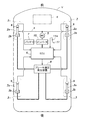
次に、図2を参照してブレーキ液圧発生装置8について説明する。本実施形態の制動システムは、ブレーキペダル11の操作量(ペダル変位量)を変位センサ11aにより検出し、その検出値に基づいて液圧発生手段としてのモータ駆動シリンダ13を駆動してブレーキ液圧を発生させる。モータ駆動シリンダ13には、電動サーボモータ12と、電動サーボモータ12に連結されたギアボックス18とが一体的に設けられていると共に、ギアボックス18にボールねじ機構を介してトルク伝達されることにより軸線方向変位するねじ溝付きロッド19と、ねじ溝付きロッド19と同軸かつ互いに直列的に配設された第1ピストン21a及び第2ピストン21bとが設けられている。
Next, the brake
これにより、ブレーキペダル11の操作量に応じて電動サーボモータ12が回転し、その回転力がギアボックス18を介してねじ溝付きロッド19の軸力に変換され、第1ピストン21aが直線運動する。このようにして、制動操作部材としてのブレーキペダル11の操作を機械的にブレーキ液圧発生シリンダに伝達してブレーキ液圧を発生させるのではなく、ブレーキペダル11の踏み込み量に応じてモータ駆動シリンダ13によりブレーキ液圧を発生させる、いわゆるブレーキ・バイ・ワイヤが構成されている。
As a result, the
また、ブレーキペダル11のアームの一端が車体に回動自在に支持されていると共に、そのブレーキペダル11の円弧運動を略直線運動に変換するロッド14の一端がブレーキペダル11のアームの中間部に連結されており、ロッド14の他端は、直列的に配設されたマスターシリンダ15の第1ピストン15aを押し込むように係合している。マスターシリンダ15には第1ピストン15aに対してロッド14とは相反する側に直列的に第2ピストン15bが配設されており、各ピストン15a・15bは戻しばね41a・41bによりそれぞれロッド14側にばね付勢されている。なお、ブレーキペダル11は、図示されない戻しばねにより図1の状態である待機位置に戻す向きにばね付勢され、かつ待機位置で図示されないストッパにより止められている。
One end of the arm of the
マスターシリンダ15には、各ピストン15a・15bの変位に応じてブレーキ液をやり取りするためのリザーバタンク16が設けられている。なお、各ピストン15a・15bには、リザーバタンク16と連通する各油路16a・16bとの間をシールするための公知構造のシール部材が各適所に設けられている。そして、マスターシリンダ15の筒内には、第1ピストン15aと第2ピストン15bとの間に第1液室17aが形成され、第2ピストン15bの第1ピストンとは相反する側に第2液室17bが形成されている。
The
上記したモータ駆動シリンダ13において、第2ピストン21bに一端部が固設された連結部材27が第1ピストン21a側に延出して、連結部材20の延出方向他端部が第1ピストン21aに対して相対的に軸線方向に所定量変位可能に支持されている。これにより、第1ピストン21aは前進(第2ピストン21b側変位)時に第2ピストン21bに対して相対的に所定量だけ変位可能であるが、第1ピストン21aの前進状態から図2の初期状態に戻る後退時には、連結部材20を介して第2ピストン21bも初期位置まで引き戻されるようになっている。なお、各ピストン21a・21bは、それぞれに対応して設けられた各戻しばね27a・27bによりロッド19側にばね付勢されている。
In the
また、モータ駆動シリンダ13には、上記リザーバタンク16に連通路22を介してそれぞれ連通する各油路22a・22bが設けられている。各ピストン21a・21bには、各油路22a・22bとの間をシールするための公知構造のシール部材が各適所に設けられている。モータ駆動シリンダ13の筒内には、第1ピストン21aと第2ピストン21bとの間に第1液圧発生室23aが形成され、第2ピストン21bの第1ピストン21aとは相反する側に第2液圧発生室23bが形成されている。
The
マスターシリンダ15の第1液室17aは油路を構成する各管路42a・42bを介して第1液圧発生室23aと接続され、マスターシリンダ15の第2液室17bは同じく油路を構成する各管路43a・43bを介して第2液圧発生室23bと接続されている。管路42a・42bからなる油路上(42aと42bとの間)には遮断弁としての常時開型の電磁弁24aが設けられ、同じく管路43a・43bからなる油路上(43aと43bとの間)にも遮断弁としての常時開型の電磁弁24bが設けられている。このように配管されていることにより、第1液圧発生室23aには、常時開状態の電磁弁24aを介してマスターシリンダ15の第1液室17aが連通し、第2液圧発生室23bには、常時開型の電磁弁24bを介してマスターシリンダ15の第2液室17bが連通する。なお、第1液室17aと電磁弁24aとの間にはマスターシリンダ側ブレーキ圧センサ25aが接続され、電磁弁24bと第2液圧発生室23bとの間にはモータ駆動シリンダ側ブレーキ圧センサ25bが接続されている。
The first
また、第2液室17bと電磁弁24bとの間には、常時閉型の電磁弁24cを介してシリンダ型のシミュレータ28が接続されている。シミュレータ28には、そのシリンダ内を分断するピストン28aが設けられ、ピストン28aの電磁弁24c側に貯液室28bが形成され、ピストン28aの貯液室28a側とは相反する側には圧縮コイルばね28cが受容されている。両電磁弁24a・24bが閉じかつ電磁弁24cが開くことにより、第2液室17bと貯液室28bとが連通し、その状態でブレーキペダル11を踏み込むと、第2液室17b内のブレーキ液が貯液室28bに入り込む。それにより圧縮される圧縮コイルばね28cの付勢力がブレーキペダル11に伝達されるため、公知のマスターシリンダとホイールシリンダとが直結されているブレーキ装置と同様の踏み込みに対する反力が得られる。
Further, a
さらに、モータ駆動シリンダ13の第1液圧発生室23aと第2液圧発生室23bとは、それぞれ各管路42c・43c及び本実施形態における例えばVSA装置26を介して複数(図示例では4つ)の各ホイールシリンダ2b・3bと連通するように配管されている。なお、VSA装置26は、ブレーキ時の車輪ロックを防ぐABS、加速時などの車輪空転を防ぐTCS(トラクションコントロールシステム)に、旋回時の横すべり抑制を加え、3つの機能をトータルにコントロールする車両挙動安定化制御システムとして公知のものであって良く、その説明を省略する。なおVSA装置26には、前輪の各ホイールシリンダ2bに対応する第1系統と、後輪の各ホイールシリンダ3bに対応する第2系統とをそれぞれ構成する各種の油圧素子を用いた各ブレーキアクチュエータ26bと、それらを制御するVSA制御ユニット26aとにより構成されている。
Furthermore, the first hydraulic
このようにして構成されたブレーキ液圧発生装置8は、上記制御ユニット6により総合的に制御される。制御ユニット6には、ストロークセンサ11aと各ブレーキ圧センサ25a・25bとの各検出信号が入力し、また車両の挙動を検出するための各種センサ(図示せず)からの検出信号が入力し、さらに電動サーボモータ12のモータ回転角信号も入力している。
The brake
制御ユニット6は、ストロークセンサ11aからの検出信号に基づき、かつ上記各種センサからの検出信号から判断した走行状況等に応じて、モータ駆動シリンダ13により発生するブレーキ液圧を制御する。さらに、本実施形態の対象車両となるハイブリッド車(または電気自動車)の場合には、モータ・ジェネレータによる回生制御を行うようにしており、制御ユニット6では、回生制御を行う場合の回生の大きさに対するモータ駆動シリンダ13によるブレーキ液圧の大きさの配分制御も行う。
The
次に、本発明に基づく弁制御回路の一例を図3のブロック図を参照して説明する。図3の回路は制御ユニット6に設けられて良く、またプログラムと組み合わせて処理されるものであって良い。
Next, an example of the valve control circuit according to the present invention will be described with reference to the block diagram of FIG. The circuit of FIG. 3 may be provided in the
図において、ストロークセンサ11aによるブレーキペダル11の検出値であるストロークSpが最大値判別部31に入力し、最大値判別部31では、ストロークSpが最大値Spfを超えている(Sp>Spf)か否かを判別する。なお、ブレーキペダル11が踏み込まれて、両電磁弁24a・24bが閉じた状態でシミュレータ28のピストン28aが底突きすると、マスターシリンダ15とシミュレータ28との間にブレーキ液が封止され、その状態ではストロークSpが制御の最大値Spfを超えた限界値(Spf+ΔSp)に達する。
In the figure, a stroke Sp, which is a detected value of the
ストロークSpが制御の最大値Spfを超えていた場合には最大値判別部31から限界値(Spf+ΔSp)が通電固定手段としての定数出力部32に出力される。ストロークSpの限界では、モータ駆動シリンダ13側の液圧(ブレーキ圧センサ25bの圧力)は回生協調制動をしていなければ一定となるが、マスターシリンダ15側のブレーキ圧(ブレーキ圧センサ25aの圧力)はブレーキペダル11の踏力の増大に応じて増大するため、ストロークSpからマスターシリンダ15側のブレーキ圧は推定できない。定数出力部32は、その場合に電磁弁24a・24bの液圧封止性能を確保するのに十分な値である所定値Idを出力する。定数出力部32から出力される所定値Idはオア回路33の2入力の一方に入力する。
When the stroke Sp exceeds the maximum control value Spf, the maximum
ストロークSpが最大値Spf以下の場合には、ストロークセンサ11aで検出された値(ストロークSp)が開弁方向駆動力設定部としての開弁電流設定部34に入力する。開弁電流設定部34では、ストロークSpの大きさに対応して電磁弁24a・24bの開弁方向電流Ioを求める。例えば、ストロークSpに対して開弁方向電流Ioが比例変化(Io=a×Sp:aは係数)するストローク−開弁電流変換マップを用いることができる。この開弁電流設定部34の出力(開弁方向電流Io)は減算器35に減算値として入力する。
When the stroke Sp is equal to or less than the maximum value Spf, the value (stroke Sp) detected by the
一方、電動サーボモータ12のモータ回転角θ信号がモータ駆動シリンダストローク設定部36に入力しており、モータ駆動シリンダストローク設定部36では、モータ回転角θの大きさに対応してモータ駆動シリンダ13のシリンダストローク量Smを求める。このシリンダストローク量Smの設定には、上記と同様に、モータ回転角θに対してシリンダストローク量Smが比例変化(Sm=b×θ:bは係数)するモータ回転角−ストローク変換マップを用いることができる。このモータ駆動シリンダストローク設定部36の出力(シリンダストローク量Sm)は閉弁方向駆動力設定部としての閉弁電流設定部37に入力する。
On the other hand, the motor rotation angle θ signal of the
閉弁電流設定部37では、シリンダストローク量Smの大きさに対応して電磁弁24a・24bの閉弁方向電流Icを求める。上記と同様に、シリンダストローク量Smに対して閉弁方向電流Icが比例変化(Ic=c×Sm:cは係数)するストローク−閉弁電流変換マップを用いることができる。この閉弁電流設定部37の出力(閉弁方向電流Ic)は上記した減算器35に加算値として入力する。なお、閉弁方向電流Icは、同様の閉弁力を電磁弁24a・24bで発生する場合の対応量である。
The valve closing
減算器35では、開弁方向電流Ioから閉弁方向電流Icを減算した偏差ΔI(=Io−Ic)を閉弁維持補助電流設定部38に出力する。閉弁維持補助電流設定部38では、偏差ΔIに基づいて電磁弁24a・24bの閉弁状態を維持する補助力に相当する推力電流となる閉弁維持補助電流Isを求める。その閉弁維持補助電流Isは、偏差ΔIに対して比例変化(Is=d×ΔdI:dは係数)するが、偏差ΔIが小さい場合には一定の下限値となり、偏差ΔIが大きい場合には一定の上限値となるように設定された偏差−推力電流変換マップを用いて求める。閉弁維持補助電流設定部38の出力(閉弁維持補助電流Is)は上記オア回路33の2入力の他方に入力する。
The
オア回路33の出力は、閉弁維持補助電流Isと定数出力部32の所定値Idとの大きい方が減算値として減算器39に入力する。その減算器39には、電源出力Wbが制限ゲイン回路40を介して設定された閉弁維持電流Ikが加算値として入力している。減算器39による結果が電磁弁24a・24bへの電流印加量の制御値Siとして電磁弁24a・24bを駆動制御する図示されない弁ドライブ回路に出力される。
As for the output of the
ここで、上記電磁弁24a・24bの一例を、図4を参照して説明する。電磁弁24a・24bはそれぞれ、図4に示すように、配管42aに連通する通路55が形成されたケーシング56と、通路55の途中に設けられた弁座57と、弁座57に着座可能な弁体58と、弁体58に連結された柱状のプランジャ59と、プランジャ59を磁力によって進退させるべく、ケーシング56に設けられたソレノイド60と、通路55内に設けられ、プランジャ59を後退させる方向に付勢するコイルばね61と有している。
Here, an example of the
また、ソレノイド60にはバッテリ7の電力が供給される。ソレノイド60に通電されていない場合には、コイルばね61によってプランジャ59は弁座57に対して後退し、弁体58は弁座57から離間し、通路55は開かれて、両管路42a・42bは連通する。ソレノイド60に通電されると、プランジャ59はソレノイド60の磁力を受けてコイルばね61の付勢力に抗して前進し、弁体58は弁座57に着座して通路55は閉塞され、両管路42a・42b間が遮断される。
In addition, the power of the
また、弁体58が弁座57に着座した電磁弁24aの閉弁状態では、モータ駆動シリンダ13からの液圧を受けることにより弁体58は弁座57側に付勢される。なお、電磁弁24bも、電磁弁24aと同様の構成を有する。
When the
次に、上記したように構成された本発明の車両用ブレーキ装置における電磁弁24a・24bの開閉制御要領について説明する。
Next, an opening / closing control procedure of the
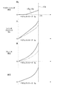
図5は、ブレーキペダル11のペダルストロークSpに対しての、マスターシリンダ液圧となる第1液室17aの液圧(実線)及び第2液室17bの液圧(二点鎖線)の変化、モータ駆動シリンダ13のシリンダストロークSmの変化、モータ駆動シリンダ13により発生するブレーキ液圧と、マスターシリンダ液圧とブレーキ液圧との差圧の変化を示す図である。
FIG. 5 shows changes in the fluid pressure (solid line) in the first
図に示されるように、ペダルストロークSpがフルストロークに至るまではストロークの変化に比例するようにシリンダストロークSmも変化するが、シリンダストロークSmは変位センサ11aに基づくだけの場合には、ペダルストロークSpがフルストロークに達したら一定値となる。それに対して、ブレーキペダル11は、マスターシリンダ15〜シミュレータ28間のブレーキ液の流れが止まったら、それ以上はストロークが増えなくなるが、その場合でも踏み込み力を増すことにより液圧(第2液室17b)は上昇し得る(図の実線)。
As shown in the figure, until the pedal stroke Sp reaches a full stroke, the cylinder stroke Sm also changes so as to be proportional to the change in the stroke. However, if the cylinder stroke Sm is only based on the
なお、モータ駆動シリンダ13のストローク変化は、例えば図の実線が最大値とすると、回生協調制御を行う等の場合には制動配分に応じて図の二点鎖線に示されるように減少する。その場合にはブレーキ液圧も減少する。
Note that the stroke change of the
また、図6を参照して、ブレーキペダル11の踏み込み変化に対する各液圧及び差圧の変化の一例を説明する。ペダルストロークSpがフルストロークに至るまで上昇することにより、モータ駆動シリンダ13で発生するブレーキ液圧(実線)と、第1液室17aで発生する液圧(二点鎖線)と、第2液室17bで発生する液圧(一点鎖線)とがそれぞれ上昇する。なお、第1液室17a及び第2液室17bの液圧は同一となる。
Moreover, with reference to FIG. 6, an example of the change of each hydraulic pressure with respect to the depression change of the
図6では、ペダルストローク11の踏み込み操作の一例を時間変化で示し、それに応じたマスターシリンダ液圧及びブレーキ液圧の変化、それらの差圧(電磁弁24a・24bの弁体58の両側に加わる圧力差)の変化が示されている。なお、第1液室17aの液圧を一点鎖線で、第2液室17bの液圧を二点鎖線で、モータ駆動シリンダ13によるブレーキ液圧を実線で示す。また、図に示されるように、本発明が適用されるブレーキ・バイ・ワイヤにおけるブレーキ装置では、マスターシリンダ15による液圧(17b)よりもモータ駆動シリンダ13による液圧(13)の方が高くなるように設計されている。
In FIG. 6, an example of the depression operation of the
図ではペダルストロークSpがフルストローク状態で踏み込み力が増大した場合について示している。この場合にはペダルストロークSpが一定であると検出されても一点鎖線に示されるようにマスターシリンダ液圧(17b)が増大する。そして、時間経過に伴って踏み込み力を解除してペダルストロークSpが低減することにより、第2液室17bの液圧が減少し、第1液室17aの液圧同じになった後には同一圧となって、ペダルストロークSpの低減に応じて低下する。このように各液圧が変化する場合には、差圧(電磁弁24a・24bの弁体58の両側に加わる圧力差)が図に示されるように変化する。
In the figure, the pedal stroke Sp is shown in the full stroke state and the stepping force increases. In this case, even if it is detected that the pedal stroke Sp is constant, the master cylinder hydraulic pressure (17b) increases as indicated by the one-dot chain line. Then, as the pedal stroke Sp is reduced by releasing the stepping force with the passage of time, the fluid pressure in the second
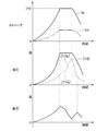
次に、フルストローク状態で第2液室17bの液圧が増大する場合の電磁弁24a・24bへの通電要領について図7を参照して説明する。ここで、電磁弁電流の波形として、電磁弁24a・24bを閉弁状態にするのに必要な閉弁方向駆動力に相当する電流を「閉弁方向」(実線)として示し、開弁状態にする電流を「開弁方向」(二点鎖線)として示す。図において、「開弁方向」の波形がフルストロークの領域で図示されていないのは、開弁方向相当電流を規定不可能なためである。
Next, a procedure for energizing the
そして、電磁弁24a・24bを閉弁方向に駆動するための印加電流を図7の最下段の二点鎖線で示されるように制御する。図の最下段で、Ivは電磁弁駆動電流(定格値)、Idは、フルストロークで発生させる減速度に対する液圧は上記したようにブレーキ圧>マスターシリンダ液圧となり、その場合における閉弁状態を維持し得る程度の所定値である。このように、ブレーキペダル11のフルストロークで上記したように踏み込み力を増大した場合にはマスターシリンダ15による液圧が増大して弁体58を開弁方向に駆動する力が増大するが、それに抗する閉弁方向の駆動力を発生可能な所定値Idの電流を流すようにしており、電磁弁24a・24bの閉弁状態が確実に維持される。なお、ブレーキペダル11の踏み込みを維持した場合で、モータ駆動シリンダ13がブレーキペダル11のストローク以外の要因で変動する場合(協調回生制動)があるため、電磁弁24a・24bの閉弁状態を維持するための電流は一定が好ましい。
Then, the applied current for driving the
フルストローク以外では、ペダルストロークSpとシリンダストローク量Smとに応じて印加電流を図7の二点鎖線に示されるように制御することにより、電磁弁24a・24bの定格値Ivに対して軽減電流を図の実線で示されるように低減することができる。これにより、電磁弁24a・24bに定格値Ivを流し続けることによる発熱を低減し得る。また、省電力効果も大となる。
Except for the full stroke, the applied current is controlled in accordance with the pedal stroke Sp and the cylinder stroke amount Sm as shown by the two-dot chain line in FIG. 7, thereby reducing the current with respect to the rated value Iv of the
2b・3b ホイールシリンダ
6 制御手段
11 ブレーキペダル(操作部材)
11a 変位センサ(操作量検出手段)
13 モータ駆動シリンダ(液圧発生手段)
15 マスターシリンダ
24a・24b 電磁弁
32 定数出力部(通電固定手段)
34 開弁電流設定部(開弁方向駆動力設定部)
37 閉弁電流設定部(閉弁方向駆動力設定部)
42a・42b・43a・43b 配管(油路)
2b,
11a Displacement sensor (operation amount detection means)
13 Motor driven cylinder (hydraulic pressure generating means)
15
34 Valve opening current setting part (valve opening direction driving force setting part)
37 Valve closing current setting part (valve closing direction driving force setting part)
42a, 42b, 43a, 43b Piping (oil passage)
Claims (4)
前記マスターシリンダに油路を介して接続されたホイールシリンダと、
前記油路上に設けられた常時開の電磁弁と、
前記操作部材の操作量を検出する操作量検出手段と、
前記油路の前記電磁弁と前記ホイールシリンダとの間に接続され、前記操作量検出手段の検出値に応じて前記油路に液圧を供給する液圧発生手段と、
前記操作量に応じて前記電磁弁及び前記液圧発生手段を制御する制御手段とを有する車両用ブレーキ装置であって、
前記電磁弁は、前記マスターシリンダによる液圧が開弁方向に作用し、前記液圧発生手段による液圧が閉弁方向に作用するように構成され、
前記制御手段は、前記操作量及び前記液圧発生手段の作動量に基づいて、前記電磁弁の閉弁状態が維持されるように前記電磁弁への通電の大きさを制御することを特徴とする車両用ブレーキ装置。 A master cylinder mechanically connected to the operating member and generating hydraulic pressure;
A wheel cylinder connected to the master cylinder via an oil passage;
A normally open solenoid valve provided on the oil passage;
An operation amount detection means for detecting an operation amount of the operation member;
Hydraulic pressure generating means connected between the solenoid valve of the oil passage and the wheel cylinder, and supplying hydraulic pressure to the oil passage according to a detection value of the operation amount detection means;
A vehicular brake device having control means for controlling the electromagnetic valve and the hydraulic pressure generating means in accordance with the operation amount;
The solenoid valve is configured such that the hydraulic pressure by the master cylinder acts in the valve opening direction, and the hydraulic pressure by the hydraulic pressure generating means acts in the valve closing direction,
The control means controls the magnitude of energization to the electromagnetic valve so that the closed state of the electromagnetic valve is maintained based on the operation amount and the operation amount of the hydraulic pressure generating means. Brake device for vehicles.
前記制御手段は、前記閉弁方向の駆動力が前記開弁方向の駆動力より上回る場合には前記電磁弁への通電を低減することを特徴とする請求項1または請求項2に記載の車両用ブレーキ装置。 A valve opening direction driving force setting unit that sets the driving force of the solenoid valve in the valve opening direction according to the operation amount, and a valve closing direction that sets the driving force of the solenoid valve in the valve closing direction according to the operation amount. A valve direction driving force setting unit,
The vehicle according to claim 1, wherein the control unit reduces energization to the electromagnetic valve when the driving force in the valve closing direction exceeds the driving force in the valve opening direction. Brake device.
Priority Applications (1)
| Application Number | Priority Date | Filing Date | Title |
|---|---|---|---|
| JP2011072905A JP2012206572A (en) | 2011-03-29 | 2011-03-29 | Vehicular brake device |
Applications Claiming Priority (1)
| Application Number | Priority Date | Filing Date | Title |
|---|---|---|---|
| JP2011072905A JP2012206572A (en) | 2011-03-29 | 2011-03-29 | Vehicular brake device |
Publications (1)
| Publication Number | Publication Date |
|---|---|
| JP2012206572A true JP2012206572A (en) | 2012-10-25 |
Family
ID=47186723
Family Applications (1)
| Application Number | Title | Priority Date | Filing Date |
|---|---|---|---|
| JP2011072905A Withdrawn JP2012206572A (en) | 2011-03-29 | 2011-03-29 | Vehicular brake device |
Country Status (1)
| Country | Link |
|---|---|
| JP (1) | JP2012206572A (en) |
-
2011
- 2011-03-29 JP JP2011072905A patent/JP2012206572A/en not_active Withdrawn
Similar Documents
| Publication | Publication Date | Title |
|---|---|---|
| JP5320380B2 (en) | Brake device for vehicle | |
| JP5411118B2 (en) | Brake device for vehicle | |
| JP5506952B2 (en) | Brake device for vehicle | |
| JP5367683B2 (en) | Brake device for vehicle | |
| JP5815183B2 (en) | Brake device for vehicle | |
| WO2012073353A1 (en) | Hydraulic brake system | |
| JP6040306B2 (en) | Brake system for vehicles | |
| JPWO2012073352A1 (en) | Hydraulic brake system | |
| JP2014213628A (en) | Vehicle brake system | |
| KR20160099950A (en) | Electro-hydraulic brake device for reducing drag of brake in vehicle | |
| JP5566873B2 (en) | Brake device for vehicle | |
| JP5555798B2 (en) | Brake device for vehicle | |
| JP6058486B2 (en) | Vehicle braking system | |
| JP5856133B2 (en) | Vehicle braking system | |
| JP5561131B2 (en) | Brake system | |
| JP2015110361A (en) | Vehicular brake device | |
| JP5652168B2 (en) | Hydraulic brake system | |
| JP2015030426A (en) | Braking device for vehicle | |
| JP2012206572A (en) | Vehicular brake device | |
| JP5719208B2 (en) | Brake device for vehicle | |
| JP6117028B2 (en) | Brake system for vehicles | |
| JP5719210B2 (en) | Brake device for vehicle | |
| JP6080709B2 (en) | Braking device for vehicle | |
| CN117755259A (en) | Vehicle braking system | |
| JP2012206586A (en) | Vehicle brake device |
Legal Events
| Date | Code | Title | Description |
|---|---|---|---|
| A300 | Withdrawal of application because of no request for examination |
Free format text: JAPANESE INTERMEDIATE CODE: A300 Effective date: 20140603 |