JP2012199102A - Electronic apparatus - Google Patents
Electronic apparatus Download PDFInfo
- Publication number
- JP2012199102A JP2012199102A JP2011063071A JP2011063071A JP2012199102A JP 2012199102 A JP2012199102 A JP 2012199102A JP 2011063071 A JP2011063071 A JP 2011063071A JP 2011063071 A JP2011063071 A JP 2011063071A JP 2012199102 A JP2012199102 A JP 2012199102A
- Authority
- JP
- Japan
- Prior art keywords
- housing
- shaft portion
- lid member
- lid
- side hinge
- Prior art date
- Legal status (The legal status is an assumption and is not a legal conclusion. Google has not performed a legal analysis and makes no representation as to the accuracy of the status listed.)
- Pending
Links
Images


Classifications
-
- Y—GENERAL TAGGING OF NEW TECHNOLOGICAL DEVELOPMENTS; GENERAL TAGGING OF CROSS-SECTIONAL TECHNOLOGIES SPANNING OVER SEVERAL SECTIONS OF THE IPC; TECHNICAL SUBJECTS COVERED BY FORMER USPC CROSS-REFERENCE ART COLLECTIONS [XRACs] AND DIGESTS
- Y02—TECHNOLOGIES OR APPLICATIONS FOR MITIGATION OR ADAPTATION AGAINST CLIMATE CHANGE
- Y02E—REDUCTION OF GREENHOUSE GAS [GHG] EMISSIONS, RELATED TO ENERGY GENERATION, TRANSMISSION OR DISTRIBUTION
- Y02E60/00—Enabling technologies; Technologies with a potential or indirect contribution to GHG emissions mitigation
- Y02E60/10—Energy storage using batteries
Landscapes
- Battery Mounting, Suspending (AREA)
- Telephone Set Structure (AREA)
Abstract
Description
本発明は、筐体に設けられた収容凹部に電池が収容され、電池を収容した収容凹部を蓋部材で覆うように構成した電子機器に関する。 The present invention relates to an electronic device configured such that a battery is accommodated in a housing recess provided in a housing, and the housing recess containing the battery is covered with a lid member.
電子機器は、通常、筐体と、筐体に収容された回路基板と、回路基板に実装されたコネクタと、筐体に設けられ、回路基板の一部およびコネクタの一部が収容されるコネクタ用の開口とを有する。筐体は、ケースおよびカバーを組み合わせることにより構成されている。 An electronic device is usually a housing, a circuit board housed in the housing, a connector mounted on the circuit board, and a connector that is provided on the housing and houses a part of the circuit board and a part of the connector. Opening. The housing is configured by combining a case and a cover.
電子機器のなかには、筐体に電池パック収納部(以下、収容凹部という)が形成され、この収容凹部に電池パックが収納され、収容凹部を覆う電池蓋(以下、蓋部材という)の一端側に係止爪が形成されるとともに他端側にロックレバーが組み付けられたものがある。
このような電子機器によれば、収容凹部を蓋部材で覆う際に、蓋部材の係止爪を筐体側に係止した後、ロックレバーを操作して筐体側に係止する。これにより、収容凹部を覆った状態に蓋部材を筐体に保持することが可能である(例えば、特許文献1)。
In an electronic device, a battery pack housing portion (hereinafter referred to as a housing recess) is formed in a housing, the battery pack is housed in the housing recess, and is provided at one end of a battery lid (hereinafter referred to as a lid member) that covers the housing recess. There is one in which a locking claw is formed and a lock lever is assembled on the other end side.
According to such an electronic device, when the housing recess is covered with the lid member, the latching claw of the lid member is latched on the housing side, and then the lock lever is operated to latch on the housing side. Thereby, it is possible to hold | maintain a cover member in a housing | casing in the state which covered the accommodation recessed part (for example, patent document 1).
また、図6に示すように、蓋部材100を筐体101に対して着脱可能かつ回動可能に取り付ける場合がある。
この場合、筐体101に軸部102を一体成形で設け、蓋部材100に一部開口104を有する軸受け部103を一体成形で設ける。そして、蓋部材100の軸受け部103の開口104から筐体101の軸部102を挿入して、蓋部材100を筐体101に対して回動させることにより、取り付ける。
Further, as shown in FIG. 6, the
In this case, the
しかしながら、図6に示したような従来の電子機器においては、蓋部材100を筐体101に取り付ける際には、蓋部材100の取付角度が所定の角度に限定され、その他の角度の場合には、蓋部材100は筐体101から脱落しないようになっている。
このため、この取付角度以外の時に、蓋部材100を無理に引っ張ったり、押したり、あるいは限界以上に蓋部材100を回動させたりすると、軸部102および軸受け部103に過大な力が作用して、破損するおそれがあるという問題があった。
However, in the conventional electronic device as shown in FIG. 6, when the
For this reason, if the
本発明は、従来の問題を解決するためになされたもので、樹脂製の軸部により回動可能に支持されている蓋部に、無理な押しつけ力や引っ張り力が作用した場合に、軸部の破損を防止できる電子機器を提供することを目的とする。 The present invention was made to solve the conventional problems, and when an excessive pressing force or pulling force is applied to the lid portion rotatably supported by the resin shaft portion, the shaft portion An object of the present invention is to provide an electronic device that can prevent damage to the device.
本発明の電子機器は、筐体と、前記筐体に設けられ、電池パックを収容する収容凹部と、前記収容凹部を覆う蓋部材と、前記筐体に対して前記蓋部材を回動させるためのヒンジ部と、を備え、前記ヒンジ部が、前記筐体に設けられた筐体側ヒンジ部と、前記蓋部材に設けられた蓋側ヒンジ部とを有し、前記蓋側ヒンジ部が、前記蓋部材に設けられて前記筐体側ヒンジ部に向かって延びる一対の腕部と、前記腕部に連結され、前記腕部の長手方向に対して直交するとともに、互いに近付く方向に突出する第1軸部および互いに離れる方向に突出する第2軸部とを有し、前記筐体側ヒンジ部が、前記第1軸部を支持する第1支持部と、前記第2軸部を支持する第2支持部とを有し、前記第1支持部が、前記収容凹部の深さ方向に沿って前記筐体から前記第1軸部が離反しないように規制する第1規制面を有し、前記第2支持部が、前記第2軸部が前記収容凹部に対して近付く方向に移動しないように規制する第2規制面を有するものである。 An electronic device according to the present invention is provided with a housing, a housing recess provided in the housing and housing the battery pack, a lid member covering the housing recess, and the lid member rotating with respect to the housing. A hinge portion, and the hinge portion includes a housing-side hinge portion provided in the housing, and a lid-side hinge portion provided in the lid member. A pair of arm portions provided on the lid member and extending toward the housing-side hinge portion, and a first shaft connected to the arm portions and orthogonal to the longitudinal direction of the arm portions and projecting toward each other And a second shaft portion projecting in a direction away from each other, the housing side hinge portion supporting the first shaft portion, and a second support portion supporting the second shaft portion And the first support portion is the case along the depth direction of the housing recess. A first regulating surface that regulates the first shaft portion so as not to separate, and the second support portion restricts the second shaft portion from moving in a direction in which the second shaft portion approaches the housing recess. It has a regulatory aspect.
本発明の電子機器によれば、ヒンジ部の第1支持部の第1規制面は、第1軸部が収容凹部の深さ方向に沿って筐体から離反しないように規制する。また、ヒンジ部の第2支持部の第2規制面は、第2軸部が収容凹部に近付く方向への移動を規制する。このため、蓋部材を無理に押し付けたり、無理に引っ張ったりした際に、別の規制面が移動を規制するので、ヒンジ部が破損するのを防止できるという効果を有する電子機器を提供できる。 According to the electronic device of the present invention, the first restriction surface of the first support portion of the hinge portion restricts the first shaft portion from separating from the housing along the depth direction of the housing recess. Moreover, the 2nd control surface of the 2nd support part of a hinge part controls the movement to the direction in which a 2nd axial part approaches an accommodation recessed part. For this reason, when the lid member is forcibly pressed or forcibly pulled, the movement of another restricting surface restricts the movement, so that it is possible to provide an electronic device having an effect of preventing the hinge portion from being damaged.
以下、本発明に係る実施形態の電子機器について、図面を用いて説明する。
図1に示すように、本発明に係る実施形態の電子機器10は、例えば携帯端末であり、略矩形体状に形成された第1筐体(筐体)20と、略矩形体状に形成された第2筐体11と、第1筐体20および第2筐体11を開閉自在に連結する連結部(図示省略)とを有する。
従って、この電子機器10は、連結部を中心として相対的に回動することにより第1筐体20および第2筐体11が互いに重なり合う携帯状態(図1参照)と、連結部を中心として相対的に回動することにより第1筐体20および第2筐体11が互いに離れる方向に展開された展開状態とを取り得る。
Hereinafter, an electronic apparatus according to an embodiment of the present invention will be described with reference to the drawings.
As shown in FIG. 1, an
Accordingly, the
第1筐体20は、下面(図1において下面)が開口した薄型矩形箱状のケース21と、ケース21の開口を塞ぐカバー22を有し、カバー22の表面(図1において下面)には操作キー等を備えた操作部が設けられている。
また、第2筐体11は矩形箱状をしており、表面(図1において下面)には、液晶表示板からなる表示部が設けられている。
The
The
第1筐体20のケース21の底面(図1においては上面)211における長手方向の一方の側には、電池パック23を収容する収容凹部24が設けられている。収納凹部24には、外側(ケース21の外部側)に第1蓋部材25が設けられ、第1蓋部材25の内側(ケース21の内部側)に蓋部材としての第2蓋部材26が設けられている。
第1蓋部材25は、第1筐体20の長手方向にスライドさせることにより、着脱可能に取り付けられる。
A housing recess 24 for housing the
The
第2蓋部材26は、収容凹部24を防水して電池パック23を水から保護するための部材であり、ヒンジ部30を介して第1筐体20に対して回動可能に設けられている。第2蓋部材26は矩形板状の部材であり、外周縁に沿ってパッキン27が取り付けられている。パッキン27は収容凹部24の開口を全周にわたって密閉する。
ヒンジ部30は、第1筐体20に設けられた筐体側ヒンジ部31と、第2蓋部材26に設けられた蓋側ヒンジ部32とを有する。
The
The
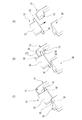
図2および図3に示すように、蓋側ヒンジ部32は、第2蓋部材26に植設されて筐体側ヒンジ部31に向かって延びる一対の腕部33、33を有する。また、腕部33には、腕部33の長手方向に対して直交するとともに互いに近付く方向に突出する第1軸部34、34と、互いに離れる方向に突出する第2軸部35、35とが設けられている。
一対の第1軸部34、34は、一対の腕部33、33の間隔の中心を通って第1筐体20の長手方向に延びる面(以後、「中心面CP」という。図4参照)に対して対称に設けられている。また、一対の第2軸部35、35も、中心面CPに対して対称位置に設けられている。
As shown in FIGS. 2 and 3, the lid
The pair of
一方、筐体側ヒンジ部31は、蓋側ヒンジ部32の一対の第1軸部34、34を支持する第1支持部36と、一対の第2軸部35、35を支持する一対の第2支持部37、37とを有する。
第1支持部36は、収容凹部24の深さ方向(図2および図3において上下方向)に沿って第1筐体20から一対の第1軸部34、34が離反しないように規制する一対の第1規制面38、38を有する。
一対の第2支持部37、37は、各々第2軸部35が収容凹部24に近付く方向(図2および図3において左下方向)に移動しないように規制する第2規制面39を有する。また、第2支持部37の前面(収容凹部24側)には、後方に向かって上昇する斜面372が設けられている。
On the other hand, the housing-
The
The pair of
第1支持部36は中心面CPを中心に設けられており、中心面CPに対して対称に第1規制面38が設けられている。従って、第1支持部36は、T字形状となっている。
また、一対の第2支持部37、37は、中心面CPに対して対称位置に設けられており、一対の第2規制面39、39も中心面CPに対して対称位置に設けられている。
The
In addition, the pair of
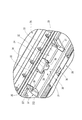
図4に示すように、蓋側ヒンジ部32において、腕部33の幅をBA1、第1軸部34の突出量をBA2、第2軸部35の突出量をBA3、全幅をBAとする。
また、筐体側ヒンジ部31において、第1規制面38の突出量をBB1、第2規制面39の幅をBB2、第1支持部36と第2支持部37との間隔をBB3、全幅をBBとする。なお、第1支持部36の上面361と、第2支持部37の上面371の高さは同一である。
As shown in FIG. 4, in the lid-
Further, in the case-
蓋側ヒンジ部32の全幅BAは、少なくとも筐体側ヒンジ部31の全幅BBよりも小さい(BA<BB)。腕部33の幅BA1は、第1支持部36と第2支持部37との間隔BB3よりも小さい(BA1<BB3)。第1軸部34の突出量BA2は、第1規制面38の突出量BB1より小さい(BA2<BB1)。そして、第2軸部35の突出量BA3は、第2規制面39の幅BB2より小さい(BA3<BB2)。
The full width BA of the lid
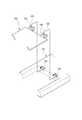
次に、第2蓋部材26の取り付け方について説明する。
まず、図5(A)に示すように、蓋側ヒンジ部32の腕部33が、筐体側ヒンジ部31の第1支持部36と第2支持部37との間の前方に位置するように位置決めする。
次いで、図5(B)に示すように、第2蓋部材26を筐体側ヒンジ部31に近付けて、第2軸部35を第2支持部37の斜面372に沿って上昇させながら、第1軸部34を第1支持部36の第1規制面38の下方へ挿入する。
Next, how to attach the
First, as illustrated in FIG. 5A, the
Next, as shown in FIG. 5 (B), the
このとき、第2軸部35側のみが上昇させられるので、腕部33が若干ねじられており、第2軸部35が第2支持部37の上面371を乗り越えたときに、腕部33の弾性力により、第2軸部35は第2規制面39の後方(収容凹部24の反対側)に下降する(図5(C)参照)。
これにより、第1軸部34が第1規制面38の下方に位置決めされるとともに、第2軸部35が第2規制面39の後方に位置決めされるので、第2蓋部材26は第1筐体20に回動可能に取り付けられる。
At this time, since only the
As a result, the
以上、説明した本発明に係る実施形態の電子機器10によれば、蓋側ヒンジ部32の第1軸部34および第2軸部35が、それぞれ筐体側ヒンジ部31の第1支持部36および第2支持部37に支持されることにより、第2蓋部材26は第1筐体20に回動可能に取り付けられる。
このとき、筐体側ヒンジ部31の第1支持部36の第1規制面38は、蓋側ヒンジ部32の第1軸部34が収容凹部24の深さ方向に沿って第1筐体20から離反しないように規制する。また、第2支持部37の第2規制面39は、第2軸部35が収容凹部24に近付く方向への移動を規制する。
このため、第2蓋部材26を無理に押し付けたり、無理に引っ張ったりする力が作用した際に、別の規制面38、39が移動を規制するので、ヒンジ部30が破損するのを防止できる。
As described above, according to the
At this time, the first regulating
For this reason, when the force which forcibly presses the
また、筐体側ヒンジ部31および蓋側ヒンジ部32を、中心面CPに対して対称形状に形成したので、着脱の際に偏った力が作用するのを防止でき、ヒンジ部30の破損を防止できる。
Further, since the housing-
なお、本発明の電子機器は、前述した実施形態に限定されるものでなく、適宜な変形,改良等が可能である。
例えば、前述した実施形態においては、第1蓋部材25および第2蓋部材26からなる二重蓋構造の場合を例示したが、1枚の蓋を有する場合でも同様に適用可能である。
Note that the electronic apparatus of the present invention is not limited to the above-described embodiment, and appropriate modifications and improvements can be made.
For example, in the above-described embodiment, the case of the double lid structure including the
以上のように、本発明にかかる電子機器では、ヒンジ部の第1支持部の第1規制面は、第1軸部が収容凹部の深さ方向に沿って筐体から離反しないように規制する。また、ヒンジ部の第2支持部の第2規制面は、第2軸部が収容凹部に近付く方向への移動を規制する。このため、蓋部材を無理に押し付けたり、無理に引っ張ったりした際に、別の規制面が移動を規制するので、ヒンジ部が破損するのを防止できるという効果を有し、筐体に設けられた収容凹部に電池が収容され、電池を収容した収容凹部を蓋部材で覆うように構成した電子機器等として有用である。 As described above, in the electronic device according to the present invention, the first restriction surface of the first support portion of the hinge portion restricts the first shaft portion from separating from the housing along the depth direction of the housing recess. . Moreover, the 2nd control surface of the 2nd support part of a hinge part controls the movement to the direction in which a 2nd axial part approaches an accommodation recessed part. For this reason, when the lid member is forcibly pressed or pulled forcibly, the movement of another regulating surface regulates the movement, so that the hinge portion can be prevented from being damaged and is provided in the housing. The battery is housed in the housing recess, and is useful as an electronic device or the like configured to cover the housing recess containing the battery with a lid member.
10 電子機器
20 第1筐体(筐体)
23 電池パック
24 収容凹部
26 第2蓋部材(蓋部材)
30 ヒンジ部
31 筐体側ヒンジ部
32 蓋側ヒンジ部
33 腕部
34 第1軸部
35 第2軸部
36 第1支持部
37 第2支持部
38 第1規制面
39 第2規制面
10
23
DESCRIPTION OF
Claims (1)
前記筐体に設けられ、電池パックを収容する収容凹部と、
前記収容凹部を覆う蓋部材と、
前記筐体に対して前記蓋部材を回動させるためのヒンジ部と、を備え、
前記ヒンジ部が、前記筐体に設けられた筐体側ヒンジ部と、前記蓋部材に設けられた蓋側ヒンジ部とを有し、
前記蓋側ヒンジ部が、
前記蓋部材に設けられて前記筐体側ヒンジ部に向かって延びる一対の腕部と、
前記腕部に連結され、前記腕部の長手方向に対して直交するとともに、互いに近付く方向に突出する第1軸部および互いに離れる方向に突出する第2軸部とを有し、
前記筐体側ヒンジ部が、
前記第1軸部を支持する第1支持部と、
前記第2軸部を支持する第2支持部とを有し、
前記第1支持部が、前記収容凹部の深さ方向に沿って前記筐体から前記第1軸部が離反しないように規制する第1規制面を有し、
前記第2支持部が、前記第2軸部が前記収容凹部に対して近付く方向に移動しないように規制する第2規制面を有する電子機器。 A housing,
A housing recess provided in the housing for housing the battery pack;
A lid member covering the housing recess;
A hinge portion for rotating the lid member relative to the housing,
The hinge portion has a housing side hinge portion provided in the housing, and a lid side hinge portion provided in the lid member,
The lid side hinge part is
A pair of arms provided on the lid member and extending toward the housing-side hinge;
A first shaft portion connected to the arm portion, orthogonal to the longitudinal direction of the arm portion and protruding in a direction approaching each other, and a second shaft portion protruding in a direction away from each other;
The housing-side hinge is
A first support part for supporting the first shaft part;
A second support part for supporting the second shaft part,
The first support portion has a first restriction surface that restricts the first shaft portion from separating from the housing along the depth direction of the housing recess,
The electronic apparatus which has a 2nd control surface which controls so that a said 2nd support part may not move to the direction in which the said 2nd axial part approaches the said accommodating recessed part.
Priority Applications (1)
| Application Number | Priority Date | Filing Date | Title |
|---|---|---|---|
| JP2011063071A JP2012199102A (en) | 2011-03-22 | 2011-03-22 | Electronic apparatus |
Applications Claiming Priority (1)
| Application Number | Priority Date | Filing Date | Title |
|---|---|---|---|
| JP2011063071A JP2012199102A (en) | 2011-03-22 | 2011-03-22 | Electronic apparatus |
Publications (1)
| Publication Number | Publication Date |
|---|---|
| JP2012199102A true JP2012199102A (en) | 2012-10-18 |
Family
ID=47181127
Family Applications (1)
| Application Number | Title | Priority Date | Filing Date |
|---|---|---|---|
| JP2011063071A Pending JP2012199102A (en) | 2011-03-22 | 2011-03-22 | Electronic apparatus |
Country Status (1)
| Country | Link |
|---|---|
| JP (1) | JP2012199102A (en) |
Cited By (2)
| Publication number | Priority date | Publication date | Assignee | Title |
|---|---|---|---|---|
| US9807891B2 (en) | 2013-09-09 | 2017-10-31 | Mitsubishi Electric Corporation | Electronic apparatus |
| JP2022519501A (en) * | 2019-04-12 | 2022-03-24 | エルジー エナジー ソリューション リミテッド | Battery module |
Citations (1)
| Publication number | Priority date | Publication date | Assignee | Title |
|---|---|---|---|---|
| JPH05506767A (en) * | 1991-03-28 | 1993-09-30 | モトローラ・インコーポレイテッド | Locking hinge device with multiple locking positions |
-
2011
- 2011-03-22 JP JP2011063071A patent/JP2012199102A/en active Pending
Patent Citations (1)
| Publication number | Priority date | Publication date | Assignee | Title |
|---|---|---|---|---|
| JPH05506767A (en) * | 1991-03-28 | 1993-09-30 | モトローラ・インコーポレイテッド | Locking hinge device with multiple locking positions |
Cited By (3)
| Publication number | Priority date | Publication date | Assignee | Title |
|---|---|---|---|---|
| US9807891B2 (en) | 2013-09-09 | 2017-10-31 | Mitsubishi Electric Corporation | Electronic apparatus |
| JP2022519501A (en) * | 2019-04-12 | 2022-03-24 | エルジー エナジー ソリューション リミテッド | Battery module |
| JP7143009B2 (en) | 2019-04-12 | 2022-09-28 | エルジー エナジー ソリューション リミテッド | battery module |
Similar Documents
| Publication | Publication Date | Title |
|---|---|---|
| JP2009093860A (en) | Electric wire cover | |
| JP6292525B2 (en) | Electronics | |
| US20120039031A1 (en) | Electronic Apparatus | |
| JP4651699B2 (en) | Electronics | |
| JP3225341U (en) | USB connector with cover | |
| JP2012199102A (en) | Electronic apparatus | |
| JP5414441B2 (en) | Information processing device | |
| EP3214766B1 (en) | Electric device | |
| JP6412772B2 (en) | Enclosure | |
| WO2012132300A1 (en) | Electronic device | |
| JP2006298301A (en) | Movable storing pocket | |
| KR20150125119A (en) | Inlet device for electric vehicle | |
| JP2015119112A (en) | Electronic device storage case | |
| JPWO2018154840A1 (en) | Appliance case | |
| CN215647274U (en) | Box body and earphone charging box | |
| JP5818311B2 (en) | Input panel and receiving box device | |
| KR102146238B1 (en) | Installation tool of usb cable and bag comprising the same | |
| JP2010212314A (en) | Housing for storing electric equipment | |
| JP3605850B2 (en) | Prize-winning equipment protection cover for pachinko machines | |
| JP4443434B2 (en) | Electrical equipment storage box | |
| JP2022130082A (en) | Equipment storage box body | |
| JP2007318507A (en) | Portable terminal | |
| CN104684318B (en) | Shell flip structure | |
| JP2016077120A (en) | Housing | |
| JP2007037712A (en) | Container |
Legal Events
| Date | Code | Title | Description |
|---|---|---|---|
| A977 | Report on retrieval |
Free format text: JAPANESE INTERMEDIATE CODE: A971007 Effective date: 20130614 |
|
| A131 | Notification of reasons for refusal |
Free format text: JAPANESE INTERMEDIATE CODE: A131 Effective date: 20130709 |
|
| A02 | Decision of refusal |
Free format text: JAPANESE INTERMEDIATE CODE: A02 Effective date: 20131105 |