JP2012198261A - Light guide plate and virtual image display provided with the same - Google Patents
Light guide plate and virtual image display provided with the same Download PDFInfo
- Publication number
- JP2012198261A JP2012198261A JP2011060481A JP2011060481A JP2012198261A JP 2012198261 A JP2012198261 A JP 2012198261A JP 2011060481 A JP2011060481 A JP 2011060481A JP 2011060481 A JP2011060481 A JP 2011060481A JP 2012198261 A JP2012198261 A JP 2012198261A
- Authority
- JP
- Japan
- Prior art keywords
- light
- image
- light guide
- guide plate
- reflection
- Prior art date
- Legal status (The legal status is an assumption and is not a legal conclusion. Google has not performed a legal analysis and makes no representation as to the accuracy of the status listed.)
- Withdrawn
Links
Images


Landscapes
- Liquid Crystal (AREA)
Abstract
Description
本発明は、頭部に装着して使用するヘッドマウントディスプレイ等に用いられる導光板及びこれを備える虚像表示装置に関する。 The present invention relates to a light guide plate used for a head mounted display or the like used by being mounted on a head, and a virtual image display device including the same.
近年、ヘッドマウントディスプレイのように虚像の形成及び観察を可能にする虚像表示装置として、導光板によって表示素子からの画像光を観察者の瞳に導くタイプのものが種々提案されている。このような虚像表示装置用の導光板として、全反射を利用して画像光を導くとともに、導光板の出口側において導光板の主面に対して所定角度をなして平行に配置される多数の部分反射面にて画像光を反射させることにより、画像光を導光板から取り出して観察者の網膜に到達させるものが知られている(特許文献1参照)。 2. Description of the Related Art In recent years, various types of virtual image display devices capable of forming and observing virtual images such as a head-mounted display have been proposed that guide image light from a display element to an observer's pupil using a light guide plate. As such a light guide plate for a virtual image display device, a large number of light beams are guided parallel to the main surface of the light guide plate at the exit side of the light guide plate while guiding image light using total reflection. There is known a technique in which image light is reflected from a partially reflecting surface so that the image light is extracted from a light guide plate and reaches an observer's retina (see Patent Document 1).
しかしながら、上記特許文献1の表示装置の場合、画像光の重複等による輝度斑を抑制するには、部分反射面間での反射率や相対的距離の精密な調整が必要となる。さらに、上記特許文献1の場合、反射により導光板から画像光を取り出す際に、光取り出し用の反射部材において光を複数回通過させる構造であるため、光の利用効率については比較的低いものとならざるを得ない。
However, in the case of the display device of
以上の技術とは異なるものとして、反射により導光板から画像光を取り出す際に、反射部材を一回通過させる構造とすることも考えられる。この場合、反射率の調整が不要で光の利用効率も高くなるが、個々の反射部材が独立するため各反射部材からの光束が横方向互いに分断される傾向が生じ、映像に明暗の縦縞が形成される可能性がある。 As a technique different from the above technique, it is also conceivable to adopt a structure in which the reflecting member is passed once when image light is extracted from the light guide plate by reflection. In this case, it is not necessary to adjust the reflectivity, and the light utilization efficiency is increased. It may be formed.
本発明は、上記背景技術の問題点に鑑みてなされたものであり、画像光の取り出しに際して映像に縞状の斑が生じることを防止できる虚像表示装置用の導光板及びこれを組み込んだ虚像表示装置を提供することを目的とする。 The present invention has been made in view of the above problems of the background art, and a light guide plate for a virtual image display device capable of preventing the occurrence of striped spots in an image upon taking out image light, and a virtual image display incorporating the same. An object is to provide an apparatus.
上記課題を解決するため、本発明に係る導光板は、(a)画像光を内部に取り込む光入射部と、(b)対向して延びる第1及び第2の全反射面を有し、光入射部から取り込まれた画像光を第1及び第2の全反射面での全反射により導く導光部と、(c)導光部を経て入射する画像光を所定の配列方向に配列される複数の反射ユニットでの光路の折り曲げによって外部へ取出す画像取出部を有する光射出部と、(d)光射出部に対向して配置されるとともに、複数の反射ユニットからの光束を当該複数の反射ユニットからの光束に平行で所定の配列方向に関して位置ズレさせた状態に分岐する分岐平行化部材とを備える。 In order to solve the above-described problems, a light guide plate according to the present invention includes (a) a light incident portion that takes in image light therein, and (b) first and second total reflection surfaces that extend opposite to each other. A light guide section that guides image light taken from the incident section by total reflection on the first and second total reflection surfaces; and (c) image light incident through the light guide section is arranged in a predetermined arrangement direction. (D) a light emitting unit having an image extracting unit that extracts the light path by bending the optical path at the plurality of reflecting units; and (d) the light emitting unit disposed opposite to the light emitting unit and reflects the light beams from the plurality of reflecting units. A branching parallelizing member that branches in a state parallel to the light flux from the unit and shifted in a predetermined arrangement direction.
上記導光板では、分岐平行化部材が複数の反射ユニットからの光束を当該複数の反射ユニットからの光束に平行で所定の配列方向に関して位置ズレさせた状態にそれぞれ分岐するので、複数の反射ユニットから分断されて取り出される光束の隙間によって映像中に縞状の輝度斑が観察される現象を抑制することができる。これにより、高品質な映像の形成や観察が可能になる。 In the light guide plate, the branching and collimating member branches the light beams from the plurality of reflection units into a state in which the light beams from the plurality of reflection units are parallel to the light beams from the plurality of reflection units and shifted with respect to a predetermined arrangement direction. It is possible to suppress a phenomenon in which striped luminance spots are observed in an image due to a gap between light beams that are separated and taken out. This makes it possible to form and observe high-quality images.
本発明の具体的な側面では、上記導光板において、分岐平行化部材は、ハーフミラーとプリズムアレイとを有するビームスプリッタアレイである。この場合、複数の反射ユニットからの光束を省スペースで個別に分岐することができる。 In a specific aspect of the present invention, in the light guide plate, the branching parallelizing member is a beam splitter array having a half mirror and a prism array. In this case, the light beams from the plurality of reflection units can be individually branched in a space-saving manner.
本発明の別の側面では、ハーフミラーの反射率が略50%である。この場合、複数の反射ユニットからの光束をバランス良く分岐することができる。 In another aspect of the invention, the reflectance of the half mirror is approximately 50%. In this case, the light beams from the plurality of reflection units can be branched with good balance.
本発明のさらに別の側面では、ハーフミラーが偏光分離膜である。この場合、複数の反射ユニットからの光束を偏光方向に応じて少ない損失で分岐することができる。 In yet another aspect of the present invention, the half mirror is a polarization separation film. In this case, the light beams from the plurality of reflection units can be branched with little loss according to the polarization direction.
本発明のさらに別の側面では、ハーフミラーが金属反射膜である。この場合、複数の反射ユニットからの光束を少ない損失で偏りなく分岐することができる。 In yet another aspect of the present invention, the half mirror is a metal reflective film. In this case, the light beams from the plurality of reflection units can be branched without deviation with little loss.
本発明のさらに別の側面では、複数の反射ユニットが、所定の配列方向に第1のピッチで周期的に配列され、ビームスプリッタアレイが、第1のピッチ以下の第2のピッチで周期的に配列されている。この場合、複数の反射ユニットからの光束をビームスプリッタアレイの構成要素によって1回以上分岐することができ、輝度斑の抑制効果を高めることができる。 In yet another aspect of the present invention, the plurality of reflection units are periodically arranged at a first pitch in a predetermined arrangement direction, and the beam splitter array is periodically arranged at a second pitch equal to or less than the first pitch. It is arranged. In this case, the light beams from the plurality of reflection units can be branched one or more times by the components of the beam splitter array, and the effect of suppressing luminance unevenness can be enhanced.
本発明のさらに別の側面では、分岐平行化部材が複屈折材料で形成されている。この場合、複数の反射ユニットからの光束を簡単な構造で個別に分岐することができる。 In still another aspect of the present invention, the branching parallelizing member is formed of a birefringent material. In this case, the light beams from the plurality of reflection units can be individually branched with a simple structure.
本発明のさらに別の側面では、複屈折材料が、方解石、複屈折液晶ポリマー、及び液晶のいずれかである。この場合、複屈折が大きな分岐平行化部材によって分岐された光束間の距離すなわち分離幅を比較的大きくすることができる。 In still another aspect of the present invention, the birefringent material is any one of calcite, a birefringent liquid crystal polymer, and liquid crystal. In this case, the distance between the light beams branched by the branching parallelizing member having a large birefringence, that is, the separation width can be made relatively large.
本発明のさらに別の側面では、反射ユニットが、第1の反射面と第1の反射面に対して所定角度をなす第2の反射面とで構成され、導光部にて導かれた画像光を第1の反射面により反射するとともに第2の反射面により第1の反射面で反射された画像光をさらに反射して光路の折り曲げを行う。この場合、第1の反射面と第2の反射面との2段階の反射で画像光の取出しが可能となる。これにより、画像取出部の各部において、一回入射させるだけで光路の折り曲げによって画像光を外部へ取り出すことが可能になる。 In still another aspect of the present invention, the reflection unit includes a first reflection surface and a second reflection surface that forms a predetermined angle with respect to the first reflection surface, and is an image guided by the light guide unit. The light is reflected by the first reflecting surface and the image light reflected by the first reflecting surface by the second reflecting surface is further reflected to bend the optical path. In this case, the image light can be extracted by two-stage reflection between the first reflecting surface and the second reflecting surface. As a result, the image light can be extracted to the outside by bending the optical path with only one incidence at each part of the image extraction unit.
上記課題を解決するため、本発明に係る虚像表示装置は、(a)上記いずれかの導光板と、(b)導光板に導かれる画像光を形成する画像形成装置とを備える。この場合、上記いずれかの導光板を用いることで、虚像表示装置は、縞状の斑の発生が抑制された良好な虚像光を射出させることができる。 In order to solve the above problems, a virtual image display device according to the present invention includes (a) any one of the above light guide plates, and (b) an image forming device that forms image light guided to the light guide plates. In this case, by using any one of the light guide plates described above, the virtual image display device can emit good virtual image light in which the occurrence of striped spots is suppressed.
〔第1実施形態〕
以下、図面を参照しつつ、本発明の第1実施形態に係る虚像表示装置用の導光板及びこれを組み込んだ虚像表示装置について説明する。
[First Embodiment]
Hereinafter, a light guide plate for a virtual image display device according to a first embodiment of the present invention and a virtual image display device incorporating the same will be described with reference to the drawings.
〔A.導光板及び虚像表示装置の構造〕
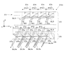
図1(A)に示す本実施形態に係る虚像表示装置100は、ヘッドマウントディスプレイに適用されるものであり、画像形成装置10と、導光板20とを一組として備える。なお、図1(A)は、図1(B)に示す導光板20のA−A断面に対応する。
[A. Structure of light guide plate and virtual image display device]
A virtual
虚像表示装置100は、観察者に虚像による画像光を認識させるとともに、観察者に外界像をシースルーで観察させるものである。画像形成装置10と導光板20とは、通常観察者の右眼および左眼に対応して一組ずつ設けられるが、右眼用と左眼用とでは左右対称であるので、ここでは左眼用のみを示し、右眼用については図示を省略している。なお、虚像表示装置100は、全体としては、例えば一般の眼鏡のような外観(不図示)を有するものとなっている。
The virtual
図1(A)に示すように、画像形成装置10は、液晶デバイス11と、投射光学系12とを有する。このうち、液晶デバイス11は、2次元的な照明光を射出する照明装置31と、透過型の空間光変調装置である液晶表示デバイス32と、これらの間に配置される射出角調整部材33とを有する。液晶表示デバイス32は、照明装置31からの照明光を空間的に変調して動画像等の表示対象となるべき画像光を形成する。投射光学系12は、液晶表示デバイス32上の各点から射出された画像光を平行状態の光束にするコリメートレンズである。射出角調整部材33は、照明光の射出角度分布を画面内の位置に応じて変化させており、液晶表示デバイス32から射出される画像光が効率的に観察者の眼EYに入射するように調整している。
As illustrated in FIG. 1A, the
図1(B)及び1(C)に示すように、導光板20は、光入射部D1と、導光部D2と、光射出部D3と、分岐平行化部材25とを備える。光入射部D1は、光入射面ISと入射光折曲面21とを有し、画像形成装置10からの画像光を光入射面ISから取り込むとともに、取り込んだ画像光を導光部D2に向けて折り曲げる。導光部D2は、全反射面形成部22を有し、取り込まれた画像光を光射出部D3に向けて伝播させる。なお、導光部D2が光束全体として導く方向であるZ方向を導光板20の導光方向とする。光射出部D3は、角度変換部である画像取出部23と光射出面OSとを有し、導光部D2で伝播された画像光の角度変換を行い光射出面OSから画像光を射出する。分岐平行化部材25は、光射出部D3の光射出面OSから射出された個々の光束をその方向を変化させることなく導光方向に位置ズレするように分岐して眼EYに入射させる。
As shown in FIGS. 1B and 1C, the
光入射部D1は、光入射面ISを、YZ面に平行で画像形成装置10に対向する表側又は観察者側の平面上に有している。また、光入射部D1は、光入射面ISの他に矩形の斜面RSを有し、当該斜面RS上には、アルミ蒸着等の成膜によりミラー層21aが形成されている。つまり、ミラー層21aと斜面RSとが協働することで入射光折曲面21を形成している。入射光折曲面21は、光入射面ISから入射し全体として+X方向に向かう画像光を、全体として−X方向に偏った+Z方向に向かわせるように折り曲げることで、画像光を導光部D2内に導く。
The light incident part D1 has a light incident surface IS on a plane on the front side or the viewer side that is parallel to the YZ plane and faces the
導光部D2は、入口側である光入射部D1側から奥側である光射出部D3側にかけて、内部に入射させた画像光を光射出部D3の画像取出部23に導くための全反射面形成部22を有している。
The light guide D2 is totally reflected to guide the image light incident inside from the light incident part D1 side which is the entrance side to the light emission part D3 side which is the back side, to the
全反射面形成部22は、導光部D2として機能するための平板状の主面であり互いに対向しYZ面に対して平行に延びる2平面として、画像光をそれぞれ全反射させる第1の全反射面22aと第2の全反射面22bとを有している。ここでは、第1の全反射面22aが画像形成装置10に近い側にあるものとし、第2の全反射面22bが画像形成装置10から遠い側にあるものとする。この場合、第1の全反射面22aは、光入射面IS及び光射出面OSと共通の面部分となっている。従って、光入射面ISや光射出面OSの一部又は全体も画像光を導く導光部D2として機能する。光入射部D1の入射光折曲面21で反射された画像光は、まず、第1の全反射面22aに入射し、全反射される。次に、当該画像光は、第2の全反射面22bに入射し、全反射される。以下この動作が繰り返されることで、画像光は、導光板20の奥側すなわち画像取出部23を設けた+Z側に導かれる。ここで、導光部D2等に用いる透明樹脂材料の屈折率nは、例えば1.5以上の高屈折率材料であるものとする。導光板20に比較的屈折率の高い透明樹脂材料を用いることで、導光板20内部で画像光を導光させやすくなり、かつ、導光板20内部での画像光の画角を比較的小さくすることができる。
The total reflection
光射出部D3は、光射出面OSの外界側に対向して微細構造である画像取出部23を配置したものとなっている。画像取出部23は、全反射面形成部22の奥側(+Z側)において、YZ面に平行な第2の全反射面22bの延長平面に略沿ってこの延長平面に近接して形成されており、全反射面形成部22を経た画像光を、所定角度で反射して光射出面OS側へ折り曲げる。画像取出部23の詳しい構造については、図2(A)等により後述する。
The light emission part D3 is configured such that an
分岐平行化部材25は、光射出部D3の光射出面OSに対向して観察者側に配置され、画像取出部23の微細構造に対応する微細構造を有する薄い板状の部材である。分岐平行化部材25は、YZ面に平行な光射出面OSに沿って延びており、光射出面OSを覆うような大きさを有している。分岐平行化部材25は、例えば低屈折率の接着剤を利用して光射出部D3の光射出面OSに貼り付けられて固定されている。分岐平行化部材25は、光射出部D3の画像取出部23の微細構造の各位置から射出された個々の光束を、当該個々の光束に平行な2以上の光束であって導光方向である+Z方向に互いに位置ズレした状態の光束に分岐する。分岐平行化部材25の詳しい構造については、図2(A)等により後述する。
The branching and collimating
〔B.画像光の光路〕
以下、画像光の光路について説明する。図1(A)に示すように、投射光学系12を経た各画像光GL1,GL2,GL3の主要成分は、導光板20の光入射面ISからそれぞれ入射した後、第1及び第2の全反射面22a,22bにおいて互いに異なる角度で全反射を繰り返す。具体的には、画像光GL1,GL2,GL3のうち、液晶デバイス11の射出面32aの中央部分から射出された画像光GL1は、入射光折曲面21で反射された後、標準反射角α0で全反射面形成部22の第2の全反射面22bに入射し、標準反射角α0を保った状態で、第1及び第2の全反射面22a,22bにおいて例えばN回(Nは自然数)全反射された後、画像取出部23の導光方向に関する中央部23kで反射され、光射出面OSからこの面に対して垂直な光軸AX方向に射出される。また、液晶デバイス11の射出面32aの一端側(+Z側)から射出された画像光GL2は、最小反射角α−で第1及び第2の全反射面22a,22bにおいて例えばN+M回全反射され、画像取出部23のうち最も光入射面側(−Z側)の周辺部23hで反射され、光射出面OSから所定の角度方向に射出される。また、液晶デバイス11の射出面32aの他端側(−Z側)から射出された画像光GL2は、最大反射角α+で第1及び第2の全反射面22a,22bにおいて例えばN−M回(Mは自然数)全反射され、画像取出部23のうち反光入射面側(+Z側)の周辺部23mで反射され、光射出面OSから所定の角度方向に射出される。以上において、光射出面OSに対向して配置される分岐平行化部材25は、画像光GL1,GL2,GL3を部分的に微少量シフトさせることで分岐するものであり、画像光GL1,GL2,GL3の射出方向を変化させないので、眼EYによって観察される無限遠の虚像に乱れは生じない。分岐平行化部材25は、詳細は後述するが、画像取出部23の微細構造によって光束が横方向互いに分断され観察画像に明暗の縦縞が形成されることを防止するために挿入されている。
[B. (Optical path of image light)
Hereinafter, the optical path of the image light will be described. As shown in FIG. 1A, the main components of the image lights GL1, GL2, and GL3 that have passed through the projection optical system 12 are incident from the light incident surface IS of the
なお、第1及び第2の全反射面22a,22bでの全反射による光の反射効率は非常に高いものであるため、上記のように画像光GL1,GL2,GL3間で反射回数が異なっていても、このような反射回数の差によって輝度低下が生じることは殆どない。また、図1(B)に示すように、縦方向すなわちY方向について見た画像光である画像光GLyは、光束全体として収束するように導光板20内を通過する。
In addition, since the reflection efficiency of light by the total reflection at the first and second total reflection surfaces 22a and 22b is very high, the number of reflections differs between the image lights GL1, GL2, and GL3 as described above. However, such a difference in the number of reflections hardly causes a decrease in luminance. Further, as shown in FIG. 1B, the image light GLY that is image light viewed in the vertical direction, that is, the Y direction passes through the
〔C.画像取出部の構造〕
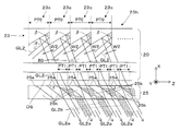
図2(A)、図3(A)、及び図3(B)に示すように、画像取出部23は、所定の軸方向であるY方向にそれぞれ延びるとともに導光方向であるZ方向に周期的に配列される反射ユニット23c,23c,…を備える。すなわち、画像取出部23は、所定の軸方向(すなわちY方向)を長手方向とする細長い形状を有する多数の反射ユニット23cを有し、これら反射ユニット23cをその横の導光方向(すなわちZ方向)の幅に等しいピッチPT0で全反射面形成部22の延びる導光方向すなわちZ方向に多数配列させることで構成されている。
[C. Image extractor structure)
As shown in FIG. 2A, FIG. 3A, and FIG. 3B, the
画像取出部23を構成する各反射ユニット23cは、導光板20の奥側すなわち+Z側に配置される第1の反射面23aと、導光板20の入口側すなわち+Z側に配置される第2の反射面23bとを1組のものとして有する。これらのうち、第2の反射面23bは、一部の光を透過可能な半透過型のミラー層24aを付随させたものであり、観察者に外界像をシースルーで観察させることを可能にしている。なお、第1の反射面23aは、例えば完全な反射型のミラー層24bを付随させたものとなっている。
Each
各反射ユニット23cは、隣接する第1及び第2の反射面23a,23bによってXZ断面視においてV字又は楔状となっており、画像取出部23全体では、XZ断面視においてZ方向に延びる断面鋸歯状となっている。なお、第1の反射面23aは、Z方向に対して垂直な面となっており、第2の反射面23bは、X方向に対して垂直な第2の全反射面22bに平行な基準面を、Y方向に延びる所定の軸方向のまわりに反時計回りに回転させて傾斜させた斜面となっている。第1の反射面23aと第2の反射面23bとの相対角度βは、具体例において例えば54.7°となっているものとする。また、以上のような構成の画像取出部23の作製については、まず、第1及び第2の反射面23a,23bとなるべき上記所定角度の傾斜面等が射出成形によって成形され、次に、当該斜面に反射面として機能させるためのミラー層を成膜し、さらに、当該ミラー層を樹脂材料で埋めるものとなっている。
Each
〔D.画像取出部による光路の折曲げ〕
以下、図2(A)〜3(C)等を参照して、画像取出部23による画像光の光路の折曲げについて説明する。ここでは、画像光のうち、画像取出部23の両端側に入射する画像光GL2及び画像光GL3について示し、他の光路については、これらと同様であるので図示等を省略する。また、各第1の反射面23aは、画像光の実際の入射面となっているが、本明細書では、画像光の全反射面22a,22bでの全反射角度を画像取出部23に対する入射角度すなわち反射ユニット23cへの入射角と呼ぶこととする。
[D. Bending the optical path by the image extraction unit)
Hereinafter, bending of the optical path of the image light by the
まず、図2(A)及び2(B)に示すように、画像光のうち全反射角度の最も小さい入射角α−で導かれた画像光GL2は、画像取出部23のうち光入射面IS(図1(A)参照)に最も近い−Z側の周辺部23hに配置された反射ユニット23cに入射する。これらの反射ユニット23cに入射した画像光GL2は、最初に第1の反射面23aで反射され、次に、第2の反射面23bで反射され、他の反射ユニット23cを経ることなく、図1(A)等に示す光射出面OSから射出される。つまり、入射角の大きな画像光GL2は、画像取出部23での1回だけの通過で所望の角度に折り曲げられ少ない損失で虚像光として観察者側に取り出される。
First, as shown in FIGS. 2 (A) and 2 (B), the image light GL2 guided at the incident angle α − having the smallest total reflection angle among the image light is the light incident surface IS of the
また、図2(A)及び2(C)に示すように、全反射角度の最も大きい入射角α+で導かれた画像光GL3は、画像取出部23のうち光入射面IS(図1(A)参照)から最も遠い+Z側の周辺部23mに配置された反射ユニット23cに入射する。これらの反射ユニット23cに入射した画像光GL3は、最初に第1の反射面23aで反射され、次に、第2の反射面23bで反射され、他の反射ユニット23cを経ることなく、図1(A)等に示す光射出面OSから射出される。つまり、入射角の小さな画像光GL3は、画像取出部23での1回だけの通過で所望の角度に折り曲げられ少ない損失で虚像光として観察者側に取り出される。
As shown in FIGS. 2A and 2C, the image light GL3 guided at the incident angle α + having the largest total reflection angle is incident on the light incident surface IS (see FIG. The light enters the
ここで、上記のような第1及び第2の反射面23a,23bでの2段階での反射の場合、図2(B)及び2(C)に示すように、各画像光の入射時の方向と射出時の方向とのなす角である折り曲げ角ψは、いずれもψ=2(R−β)(R:直角)であり、入射角α0,α−,α+等の値によらず一定である。これにより、画像光を全体として観察者の眼EYに集めるような角度状態で効率的に取り出すことが可能となる。
Here, in the case of the two-stage reflection on the first and second reflecting
なお、眼EY側に射出される画像光GL2の角度θ2と画像光GL3の角度θ3とは、大きさが略等しく逆向きとなっており、画像光による虚像の画角に相当するものとなっている。 Note that the angle θ2 of the image light GL2 emitted to the eye EY side and the angle θ3 of the image light GL3 are substantially equal and opposite to each other, and correspond to the angle of view of the virtual image by the image light. ing.
〔E.画像取出部における有効光束幅の制限〕
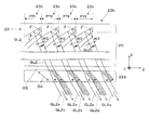
ここで、図3(A)及び3(B)により、画像取出部23における画像光の有効光束幅の制限について説明する。画像取出部23すなわち反射ユニット23cで取り出される画像光の有効光束幅は、反射ユニット23cのサイズと、反射ユニット23cに対して入射する画像光の入射角によって決まる。例えば、図示のように、周辺部23hと周辺部23mとを比較した場合、周辺部23hにおける各反射ユニット23cでの有効光束幅W2は、周辺部23mにおける各反射ユニット23cでの有効光束幅W3よりも大きくなっている。これら有効光束幅W2,W3によって例示する画像光の各光束の有効光束幅には、各画像光の入射角αや各反射ユニット23cのピッチPT0の大きさから制限がある。例えば、画像光GL3の場合、反射ユニット23cに入射できる幅(ピッチPT0の大きさに相当)の範囲内に限られるため、その有効光束幅W3は、
W3=d×sin(R−α+)(R:直角)
となる。このような制限が、いずれの光束の有効光束幅についてもあるため、画像光の各光束間には、光が届かない隙間BDが存在する。この隙間BDは、Z方向に配列される反射ユニット23cの境界の数だけ存在する。これらの隙間BDは、画像取出部23の置かれる観察者の眼の前数センチ程度のところにあるものとなるため直視されることはないが、観察者にとっては、映像中の縦縞状の斑として認識される。このため、本実施形態では、画像取出部23に対向して分岐平行化部材25を設けることで、映像における縞状の斑の発生を抑えている。つまり、分岐平行化部材25によって、各反射ユニット23cから射出された画像光GL2,GL3を、その射出方向を維持したまま反射ユニット23cの配列方向に関して位置ズレした状態の成分GL2a,GL2b,GL3a,GL3bに分岐することで、画像光GL2,GL3のデューティー比を倍増させて、縞状の輝度斑の発生を防止している。
[E. (Restriction of effective luminous flux width at image extraction part)
Here, with reference to FIGS. 3A and 3B, the limitation on the effective luminous flux width of the image light in the
W3 = d × sin (R−α +) (R: right angle)
It becomes. Since there is such a restriction on the effective light flux width of any light flux, a gap BD through which light does not reach exists between the light fluxes of the image light. There are as many gaps BD as the boundaries of the
〔F.分岐平行化部材の構造〕
図3(A)及び3(B)に示すように、分岐平行化部材25は、ハーフミラー25aとプリズム25bとを有し、これらのハーフミラー25aとプリズム25bとを交互に配置して平板状とした構造を有するビームスプリッタアレイである。ここで、ハーフミラー25aは、隣接する一対のプリズム25bに挟まれた偏光分離膜であり、Y方向を長手方向としてY方向に延びている。ここで、偏光分離膜は、例えば誘電体多層膜で形成される。ハーフミラー25aは、光射出部D3の光射出面OSに平行な基準面を、Y方向に延びる所定の軸方向のまわりに時計回り又は半時計回りに回転させて傾斜角τだけ傾斜させた斜面となっている。全てのハーフミラー25aは、光射出面OSに対して傾斜角τだけ傾斜して互いに平行であり、全体として導光方向に平行なZ方向に配列されている。この際、ハーフミラー25aを配置するピッチは、PT1としており、反射ユニット23cのピッチPT0の1/2となっている。ハーフミラー25aは、図3(A)に示すように、入射した画像光GL2のうちP偏光の第1成分GL2aを透過させ、S偏光の第2成分GL2bを反射する。また、ハーフミラー25aは、図3(B)に示すように、入射した画像光GL3のうちP偏光の第1成分GL3aを透過させ、S偏光の第2成分GL3bを反射する。プリズム25bは、Z方向の両端を除いてYZ断面が平行四辺形となっており、Y方向を長手方向としてY方向に延びている。これらのプリズム25bは、斜面同士を接合することにより、全体として導光方向に平行なZ方向に配列されている。
[F. (Branch parallel member structure)
As shown in FIGS. 3A and 3B, the branching parallelizing
〔G.分岐平行化部材による光束の分岐〕
図3(A)に示すように、反射ユニット23cから射出された画像光GL2は、分岐平行化部材25のハーフミラー25aに入射して、直進するP偏光の第1成分GL2aと反射されるS偏光の第2成分GL2bとに分岐される。直進・通過するP偏光の第1成分GL2aは、そのまま分岐平行化部材25から射出されるが、反射されたS偏光の第2成分GL2bは、隣接するハーフミラー25aで再度反射されてP偏光の第1成分GL2aと平行になり、分岐平行化部材25から射出される。つまり、画像光GL2は、これに平行な第1成分GL2aと第2成分GL2bとに分岐され、両成分GL2a,GL2bは、導光方向である+Z方向に関して互いに位置ズレした状態となっている。この際、第1成分GL2aの光束幅と第2成分GL2bの光束幅とは維持されるので、両成分GL2a,GL2bを合わせた光束幅は、重複がなければ2倍となる。さらに、画像光GL2は、液晶デバイス11にランダム偏光板又は偏光解消板等を組み込むことによりP偏光とS偏光とを均等に含むものとでき、ハーフミラー25aによる分岐比を略50%とできるので、両成分GL2a,GL2bの強度を等しくできる。つまり、分岐平行化部材25を通すことで画像光GL2の導光方向(+Z方向)のデューティー比を2倍にして隙間BDを減少させることができので、画像取出部23の反射ユニット23cによって光束が導光方向(+Z方向)に分断され観察画像に明暗の縦縞が形成されることを防止することができる
[G. (Branching of luminous flux by branching and collimating member)
As shown in FIG. 3A, the image light GL2 emitted from the
図3(B)に示すように、反射ユニット23cから射出された画像光GL3は、分岐平行化部材25のハーフミラー25aに入射して、直進・通過するP偏光の第1成分GL3aと反射されるS偏光の第2成分GL3bとに分岐される。直進するP偏光の第1成分GL3aは、そのまま分岐平行化部材25から射出されるが、反射されたS偏光の第2成分GL3bは、隣接するハーフミラー25aで再度反射されてP偏光の第1成分GL3aと平行になり、分岐平行化部材25から射出される。つまり、画像光GL3は、これに平行な第1成分GL3aと第2成分GL3bとに分岐され、両成分GL3a,GL3bは、導光方向である+Z方向に関して互いに位置ズレした状態となっている。この際、第1成分GL3aの光束幅と第2成分GL3bの光束幅とは維持されるので、両成分GL3a,GL3bを合わせた光束幅は、重複がなければ2倍となる。さらに、画像光GL3は、液晶デバイス11にランダム偏光板等を組み込むことによりP偏光とS偏光とを均等に含むものとでき、ハーフミラー25aによる分岐比を略50%とできるので、両成分GL3a,GL3bの強度を等しくできる。つまり、分岐平行化部材25を通すことで画像光GL3の導光方向(+Z方向)のデューティー比を2倍にして隙間BDを減少させることができるので、画像取出部23の反射ユニット23cによって光束が導光方向(+Z方向)に分断され観察画像に明暗の縦縞が形成されることを防止することができる。
As shown in FIG. 3B, the image light GL3 emitted from the
以上は、周辺部23h,23mからの画像光GL2,GL3についての説明であったが、中央部23kからの画像光GL1についても、光束の分岐によって導光方向(+Z方向)のデューティー比を増加させ隙間BDを減少させることができる。
The above is a description of the image lights GL2 and GL3 from the
なお、以上では、ハーフミラー25aを配置するピッチPT1が反射ユニット23cを配置するピッチPT0の1/2としたが、ハーフミラー25aのピッチPT1は、反射ユニット23cのピッチPT0以下で適宜増減することができる。例えば図4に示すように、中央部23kから奥側の周辺部23mで、ハーフミラー25aのピッチPT1を反射ユニット23cのピッチPT0と等しくすることもできる。この場合も、中央部23kから入口側の周辺部23hでは、ハーフミラー25aのピッチPT1を反射ユニット23cのピッチPT0の1/2のままとする。
In the above description, the pitch PT1 at which the
以上のように、本実施形態の導光板20等によれば、分岐平行化部材25が画像取出部23に設けた多数の反射ユニット23cからの画像光GL2,GL3を当該複数の反射ユニット23cからの光束に平行で導光方向(+Z方向)に関して位置ズレさせた成分GL2a,GL2b,GL3a,GL3bにそれぞれ分岐するので、複数の反射ユニット23cから分断されて取り出される画像光GL2,GL3の隙間によって映像中に縞状の輝度斑が観察される現象を抑制することができる。これにより、高品質な映像の形成や観察が可能になる。
As described above, according to the
〔第2実施形態〕
以下、図5を参照して、第2実施形態に係る導光板について説明する。第2実施形態に係る導光板は、図1(A)等に示す第1実施形態に係る導光板20の要部を変形したものであり、共通する部分については説明を省略する。
[Second Embodiment]
Hereinafter, the light guide plate according to the second embodiment will be described with reference to FIG. 5. The light guide plate according to the second embodiment is a modification of the main part of the
図5に示すように、本実施形態の場合、分岐平行化部材25を構成するハーフミラー25eは、偏光分離膜ではなく、金属反射膜でできている。この場合、画像光GL2,GL3がP偏光とS偏光とを均等に含むものでなくても、金属反射膜の厚み等の設定によって、ハーフミラー25eによる分岐比を略50%とできる。なお、金属反射膜の場合、ハーフミラー25eでの分岐を簡易に複数回とできるので、画像光GL2,GL3をより多く分岐してデューティー比を1に近づけることができる。
As shown in FIG. 5, in the case of this embodiment, the
〔第3実施形態〕
以下、図6参照して、第3実施形態に係る導光板について説明する。第3実施形態に係る導光板は、図1(A)等に示す第1実施形態に係る導光板20の要部を変形したものであり、共通する部分についっては説明を省略する。
[Third Embodiment]
The light guide plate according to the third embodiment will be described below with reference to FIG. The light guide plate according to the third embodiment is a modification of the main part of the
図6に示すように、本実施形態の場合、複屈折材料で形成され板状又は層状に配置される分岐平行化部材225を用いている。分岐平行化部材225の具体的な材料としては、方解石、複屈折液晶ポリマー、液晶等を用いることができる。この場合、分岐平行化部材225は、例えばXZ面内に光学軸OAを有しており、画像光GL2のうち光学軸OAに垂直な偏光成分である第1成分GL2aは、正常光線として標準的な屈折率でスネルの法則に従って屈折されて分岐平行化部材225を通過するが、画像光GL2のうち光学軸OAに水平な偏光成分を含む第2成分GL2bは、異常光線として分岐平行化部材225で異常に屈折されて通過する。これにより、画像光GL2を分岐することができ、分岐後の第1成分GL2aと第2成分GL2bとを導光方向である+Z方向に関して互いに位置ズレした状態とでき、第1成分GL2aの強度と第2成分GL2bの強度とを略一致させることができる。分岐平行化部材225を方解石から作製する場合、方解石が大きな複屈折を示すので、第1成分GL2aと第2成分GL2bとを含む画像光GL2を広げてデューティー比を大きくする効果が大きい。同様に、分岐平行化部材225により画像光GL3を広げてデューティー比を比較的大きくすることができる。複屈折液晶ポリマーは、分子構造が鎖のように細長い形状を有しており、分子配列を規則正しくすることによって複屈折性を持たせることができる。また、複屈折液晶ポリマーは、ポリマー材料ゆえに柔らかく、破損して鋭利な破片等になりにくいので、危険性が低い。液晶は、複屈折液晶ポリマーと同様に鎖状の細長い分子構造を有しており、分子配列を規則正しくすることによって複屈折性を持たせることができる。また、液晶は、これを保持するための基板材料を柔らかすることができ、これに適当な処理を施して硬化させても柔らかくでき、破損して鋭利な破片等が発生しくいので、危険性が低い。
As shown in FIG. 6, in the case of the present embodiment, a branching parallelizing
第3実施形態の導光板によれば、分岐平行化部材225が複屈折材料で形成されているので、画像取出部23に設けた多数の反射ユニット23cからの光束を簡単な構造で個別に分岐することができる。
According to the light guide plate of the third embodiment, since the branching and collimating
〔その他〕
以上実施形態に即して本発明を説明したが、本発明は、上記の実施形態に限られるものではなく、その要旨を逸脱しない範囲において種々の態様において実施することが可能であり、例えば次のような変形も可能である。
[Others]
Although the present invention has been described based on the above embodiments, the present invention is not limited to the above embodiments, and can be implemented in various modes without departing from the gist thereof. Such modifications are also possible.
上記の説明では、画像表示素子として、透過型の液晶デバイス11を用いているが、画像表示素子としては、透過型の液晶デバイスに限らず種々のものを利用可能である。例えば、反射型の液晶パネルを用いた構成も可能であり、液晶デバイス11に代えてデジタル・マイクロミラー・デバイス等を用いることもできる。また、LEDアレイやOLED(有機EL)などに代表される自発光型素子用いた構成も可能である。さらに、レーザー光源とポリゴンミラーその他のスキャナーとを組みあわせたレーザースキャナーを用いた構成も可能である。なお、液晶デバイス11やその光源において、画像取出部23の光取出特性を考慮して輝度パターンの調整を行うこともできる。
In the above description, the transmissive
上記の説明では、虚像表示装置100は、右眼及び左眼の双方に対応して、一組ずつ画像形成装置10及び導光板20を備えるとしているが、右眼又は左眼のいずれか一方に対してのみ画像形成装置10と導光板20とを設け画像を片眼視する構成にしてもよい。
In the above description, the virtual
上記の説明では、シースルー型の虚像表示装置について説明しているが、外界像を観察させる必要がない場合、第1〜第3実施形態において、第1及び第2の反射面23a,23b双方の光反射率を略100%にすることが可能である。
In the above description, the see-through type virtual image display device has been described. However, when it is not necessary to observe an external image, in the first to third embodiments, both of the first and second reflecting
上記の説明では、光入射面ISと光射出面OSとを同一の平面上に配置しているが、これに限らず、例えば、光入射面ISを第1の全反射面22aと同一の平面上に配置し、光射出面OSを第2の全反射面22bと同一の平面上に配置することもできる。
In the above description, the light incident surface IS and the light exit surface OS are arranged on the same plane. However, the present invention is not limited to this. For example, the light incident surface IS is the same plane as the first
上記の説明では、入射光折曲面21を構成するミラー層21aや斜面RSの角度について特に触れていないが、本発明は、ミラー層21a等の光軸AXに対する角度を用途や仕様に応じて様々な値とすることができる。
In the above description, the angles of the
上記の説明では、反射ユニット23cによるV字状の溝は、先端を尖った状態で図示しているが、V字状の溝の形状については、これに限らず、先端を平らにカットしているものや先端にRを付けているものであってもよい。
In the above description, the V-shaped groove formed by the
上記の説明では、実施形態の虚像表示装置100がヘッドマウントディスプレイであるとして具体的な説明を行ったが、実施形態の虚像表示装置100は、ヘッドアップディスプレイに改変することもできる。
In the above description, the virtual
上記の説明では、第1及び第2の全反射面22a,22bにおいて、表面上にミラーやハーフミラー等を施すことなく空気との界面により画像光を全反射させて導くものとしているが、本願発明における全反射については、第1及び第2の全反射面22a,22b上の全体又は一部にミラーコートや、ハーフミラー膜が形成されてなされる反射も含むものとする。例えば、画像光の入射角が全反射条件を満たした上で、全反射面22a,22bの全体又は一部にミラーコート等が施され、実質的に全ての画像光を反射する場合も含まれる。また、十分な明るさの画像光を得られるのであれば、多少透過性のあるミラーによって全反射面22a,22bの全体又は一部がコートされていてもよい。 In the above description, in the first and second total reflection surfaces 22a and 22b, image light is totally reflected and guided by the interface with air without applying a mirror, a half mirror, or the like on the surface. The total reflection in the present invention includes reflection formed by forming a mirror coat or a half mirror film on the whole or a part of the first and second total reflection surfaces 22a and 22b. For example, the case where the incident angle of the image light satisfies the total reflection condition and the whole or a part of the total reflection surfaces 22a and 22b is mirror-coated to reflect substantially all the image light. . Moreover, as long as image light with sufficient brightness can be obtained, the whole or a part of the total reflection surfaces 22a and 22b may be coated with a somewhat transmissive mirror.
10…画像形成装置、 11…液晶デバイス、 12…投射光学系、 20…導光板、 21…入射光折曲面、 21a…ミラー層、 22…全反射面形成部、 22a…第1全反射面、 22b…第2全反射面、 23a,23b…反射面、 23c…反射ユニット、 23h,23m…周辺部、 23k…中央部、 24a,24b…ミラー層、 25…分岐平行化部材、 25a,25e…ハーフミラー、 25b…プリズム、 31…照明装置、 32…液晶表示デバイス、 100…虚像表示装置、 225…分岐平行化部材、 AX…光軸、 BD…隙間、 D1…光入射部、 D2…導光部、 D3…光射出部、 EY…眼、 GL1,GL2,GL3…画像光、 GL2a…第1成分、 GL2b…第2成分、 GL3a…第1成分、 GL3b…第2成分、 IS…光入射面、 OS…光射出面、 PT0,PT1…ピッチ、 RS…斜面、 W2,W3…有効光束幅
DESCRIPTION OF
Claims (10)
対向して延びる第1及び第2の全反射面を有し、前記光入射部から取り込まれた前記画像光を前記第1及び第2の全反射面での全反射により導く導光部と、
前記導光部を経て入射する前記画像光を所定の配列方向に配列される前記複数の反射ユニットでの光路の折り曲げによって外部へ取出す画像取出部を有する光射出部と、
前記光射出部に対向して配置されるとともに、前記複数の反射ユニットからの光束を当該複数の反射ユニットからの光束に平行で前記所定の配列方向に関して位置ズレさせた状態に分岐する分岐平行化部材とを備える、導光板。 A light incident part for taking image light inside;
A light guide unit having first and second total reflection surfaces extending opposite to each other, and guiding the image light captured from the light incident unit by total reflection on the first and second total reflection surfaces;
A light emitting unit having an image extraction unit that extracts the image light incident through the light guide unit to the outside by bending of an optical path in the plurality of reflection units arranged in a predetermined arrangement direction;
Branched parallelization that is arranged opposite to the light emitting portion and branches into a state in which the light beams from the plurality of reflection units are parallel to the light beams from the plurality of reflection units and are displaced with respect to the predetermined arrangement direction. A light guide plate comprising a member.
前記ビームスプリッタアレイは、前記第1のピッチ以下の第2のピッチで周期的に配列されている、請求項2から5までのずれか一項に記載の導光板。 The plurality of reflection units are periodically arranged at a first pitch in the predetermined arrangement direction,
The light guide plate according to claim 2, wherein the beam splitter array is periodically arranged at a second pitch equal to or less than the first pitch.
前記導光板に導かれる前記画像光を形成する画像形成装置と、
を備える虚像表示装置。 The light guide plate according to any one of claims 1 to 9,
An image forming apparatus that forms the image light guided to the light guide plate;
A virtual image display device.
Priority Applications (1)
| Application Number | Priority Date | Filing Date | Title |
|---|---|---|---|
| JP2011060481A JP2012198261A (en) | 2011-03-18 | 2011-03-18 | Light guide plate and virtual image display provided with the same |
Applications Claiming Priority (1)
| Application Number | Priority Date | Filing Date | Title |
|---|---|---|---|
| JP2011060481A JP2012198261A (en) | 2011-03-18 | 2011-03-18 | Light guide plate and virtual image display provided with the same |
Publications (1)
| Publication Number | Publication Date |
|---|---|
| JP2012198261A true JP2012198261A (en) | 2012-10-18 |
Family
ID=47180581
Family Applications (1)
| Application Number | Title | Priority Date | Filing Date |
|---|---|---|---|
| JP2011060481A Withdrawn JP2012198261A (en) | 2011-03-18 | 2011-03-18 | Light guide plate and virtual image display provided with the same |
Country Status (1)
| Country | Link |
|---|---|
| JP (1) | JP2012198261A (en) |
Cited By (4)
| Publication number | Priority date | Publication date | Assignee | Title |
|---|---|---|---|---|
| JP2016042136A (en) * | 2014-08-18 | 2016-03-31 | セイコーエプソン株式会社 | Light guide device and virtual image display device |
| CN106796348A (en) * | 2014-08-18 | 2017-05-31 | 精工爱普生株式会社 | Guiding device and virtual image display apparatus |
| US11567371B2 (en) | 2016-12-14 | 2023-01-31 | Magic Leap, Inc. | Patterning of liquid crystals using soft-imprint replication of surface alignment patterns |
| US11733443B2 (en) | 2015-06-15 | 2023-08-22 | Magic Leap, Inc. | Virtual and augmented reality systems and methods |
-
2011
- 2011-03-18 JP JP2011060481A patent/JP2012198261A/en not_active Withdrawn
Cited By (7)
| Publication number | Priority date | Publication date | Assignee | Title |
|---|---|---|---|---|
| JP2016042136A (en) * | 2014-08-18 | 2016-03-31 | セイコーエプソン株式会社 | Light guide device and virtual image display device |
| CN106796348A (en) * | 2014-08-18 | 2017-05-31 | 精工爱普生株式会社 | Guiding device and virtual image display apparatus |
| US10108015B2 (en) | 2014-08-18 | 2018-10-23 | Seiko Epson Corporation | Light guide device and virtual image display apparatus |
| CN106796348B (en) * | 2014-08-18 | 2019-05-03 | 精工爱普生株式会社 | Guiding device and virtual image display apparatus |
| US11733443B2 (en) | 2015-06-15 | 2023-08-22 | Magic Leap, Inc. | Virtual and augmented reality systems and methods |
| US11789189B2 (en) | 2015-06-15 | 2023-10-17 | Magic Leap, Inc. | Display system with optical elements for in-coupling multiplexed light streams |
| US11567371B2 (en) | 2016-12-14 | 2023-01-31 | Magic Leap, Inc. | Patterning of liquid crystals using soft-imprint replication of surface alignment patterns |
Similar Documents
| Publication | Publication Date | Title |
|---|---|---|
| US11531201B2 (en) | Compact head-mounted display system having uniform image | |
| KR102537642B1 (en) | LCOS lighting via LOE | |
| US9904063B2 (en) | Collimating display and methods | |
| JP5459150B2 (en) | Light guide plate and virtual image display device including the same | |
| EP2732328B1 (en) | Eyepiece for near-to-eye display with multi-reflectors | |
| JP5703875B2 (en) | Light guide plate and virtual image display device including the same | |
| JP6409401B2 (en) | Light guide device and virtual image display device | |
| JP2018205448A (en) | Display device and illumination device | |
| JP5408048B2 (en) | Light guide plate for virtual image display device and virtual image display device | |
| CN112969955A (en) | Optical device and system with dichroic beamsplitter color combiner | |
| JP5803082B2 (en) | Virtual image display device | |
| CN107861243B (en) | Optical element and display device | |
| JP2012123147A (en) | Light guide plate, method for manufacturing light guide plate and virtual image display device | |
| JP7216665B2 (en) | Display device and head mounted display | |
| JP2017049511A (en) | Light guide device and virtual image display device | |
| JP2012198261A (en) | Light guide plate and virtual image display provided with the same | |
| JP2017161564A (en) | Light guide device and virtual image display device | |
| JP5703880B2 (en) | Light guide plate and virtual image display device including the same | |
| JP2019197079A (en) | Virtual image display device | |
| JP6657943B2 (en) | Light guide and virtual image display | |
| JP2012098324A (en) | Light guide plate and virtual image display device having the same | |
| JP2017161563A (en) | Light guide device and virtual image display device | |
| JP2018055085A (en) | Optical element and display device | |
| JP5983841B2 (en) | Virtual image display device |
Legal Events
| Date | Code | Title | Description |
|---|---|---|---|
| A300 | Withdrawal of application because of no request for examination |
Free format text: JAPANESE INTERMEDIATE CODE: A300 Effective date: 20140603 |