JP2012192499A - Parallel link robot - Google Patents

Parallel link robot Download PDF

Info

Publication number
JP2012192499A
JP2012192499A JP2011058994A JP2011058994A JP2012192499A JP 2012192499 A JP2012192499 A JP 2012192499A JP 2011058994 A JP2011058994 A JP 2011058994A JP 2011058994 A JP2011058994 A JP 2011058994A JP 2012192499 A JP2012192499 A JP 2012192499A
Authority
JP
Japan
Prior art keywords
actuator
output member
link
shaft
motor
Prior art date
Legal status (The legal status is an assumption and is not a legal conclusion. Google has not performed a legal analysis and makes no representation as to the accuracy of the status listed.)
Pending
Application number
JP2011058994A
Other languages
Japanese (ja)
Other versions
JP2012192499A5 (en
Inventor
Ryuichi Negishi
隆一 根岸
Kimikazu Miyamoto
侯一 宮本
Hisashi Kin
久 金
Current Assignee (The listed assignees may be inaccurate. Google has not performed a legal analysis and makes no representation or warranty as to the accuracy of the list.)
Canon Electronics Inc
Original Assignee
Canon Electronics Inc
Priority date (The priority date is an assumption and is not a legal conclusion. Google has not performed a legal analysis and makes no representation as to the accuracy of the date listed.)
Filing date
Publication date
Application filed by Canon Electronics Inc filed Critical Canon Electronics Inc
Priority to JP2011058994A priority Critical patent/JP2012192499A/en
Publication of JP2012192499A publication Critical patent/JP2012192499A/en
Publication of JP2012192499A5 publication Critical patent/JP2012192499A5/ja
Pending legal-status Critical Current

Links

Images

Abstract

PROBLEM TO BE SOLVED: To achieve a structure that allows work etc. on a workpiece to be performed in a clean environment.SOLUTION: An output member 102 is moved in a horizontal direction by first and second motors 104, 105. The output member 102 is moved in a vertical direction by a third motor 108. The output member 102 is turned around a vertical axis by a fourth motor 110. Link mechanisms 106, 107, 109, 112 are provided respectively between the output member 102 and the first, second, third and fourth motors 104, 105, 108, 110. The output member 102 is movable in vertical and horizontal directions and rotatable around the vertical axis without inclining the output member 102 with respect to the vertical direction. The first, second, third and fourth motors 104, 105, 108, 110 are arranged in positions horizontally off the moving region of the output member 102.

Description

本発明は、複数のアクチュエータとリンク機構とを組み合わせて構成され、物品の加工や組み立て等の作業に用いるパラレルリンクロボットに関する。   The present invention relates to a parallel link robot configured by combining a plurality of actuators and a link mechanism and used for work such as processing and assembly of an article.

パラレルリンクロボットとして、例えば、図12に示すような構造が知られている(特許文献1参照)。図12のパラレルリンクロボット1は、3組の平行リンク機構2と、3個のモータ3と、工具などが装着される出力部材4とを有する。そして、3個のモータ3でそれぞれ平行リンク機構2を介して、出力部材4の鉛直方向及び水平方向の移動を行えるようにしている。また、伝動部材5を不図示のモータにより回転駆動することにより、出力部材4を回動させられるようにしている。この伝動部材5は、出力部材4の鉛直方向及び水平方向の移動に追従しつつ、回転伝達が行えるように支持されている。また、図12の構造の場合、各モータ3及びその可動部は、ワークの上側に配置されている。   For example, a structure as shown in FIG. 12 is known as a parallel link robot (see Patent Document 1). The parallel link robot 1 in FIG. 12 includes three sets of parallel link mechanisms 2, three motors 3, and an output member 4 on which tools and the like are mounted. The three motors 3 can move the output member 4 in the vertical direction and the horizontal direction via the parallel link mechanism 2 respectively. Further, the output member 4 can be rotated by rotationally driving the transmission member 5 by a motor (not shown). The transmission member 5 is supported so as to transmit rotation while following the movement of the output member 4 in the vertical and horizontal directions. In the case of the structure of FIG. 12, each motor 3 and its movable part are arranged on the upper side of the workpiece.

特開2010−173019号公報JP 2010-173019 A

上述の特許文献1に記載された構造の場合、パラレルリンクロボット1により加工や組み付け等の作業が施されるワークの上側に、ロボット1の駆動源である各モータ3を含む機構部がある。このため、モータから発生するゴミ等がワークに落下しワークを汚染するという不都合があった。即ち、ワークがロボット1の機構部の下側に位置すると、機構部の駆動により例えばモータに付着したごみなどの異物がワークに落下して、ワークを汚染する可能性がある。特に、クリーンな環境でワークの加工などを行う場合、極僅かな異物が品質に影響を与えてしまう。   In the case of the structure described in Patent Document 1 described above, there is a mechanism unit including each motor 3 that is a drive source of the robot 1 above a work to be processed or assembled by the parallel link robot 1. For this reason, there is an inconvenience that dust generated from the motor falls onto the work and contaminates the work. That is, when the workpiece is positioned below the mechanism portion of the robot 1, foreign matter such as dust attached to the motor may fall on the workpiece due to the driving of the mechanism portion, and the workpiece may be contaminated. In particular, when a workpiece is processed in a clean environment, a very small amount of foreign matter affects the quality.

本発明は、このような事情に鑑み、クリーンな環境でワークに対して作業等を行える構造を実現すべく発明したものである。 In view of such circumstances, the present invention was invented to realize a structure capable of performing work and the like on a workpiece in a clean environment.

本発明は、鉛直方向と略平行な回転軸を有する出力部材と、前記出力部材を前記回転軸と交差する方向に移動させる第1アクチュエータ及び第2アクチュエータと、前記出力部材を概ね鉛直方向に移動させる第3アクチュエータと、前記出力部材を前記回転軸回りに回動させる第4アクチュエータと、前記出力部材と、前記第1、第2、第3、第4アクチュエータとの間にそれぞれ設けられた複数のリンク機構と、を備え、前記第1、第2、第3アクチュエータ及び前記複数のリンク機構により、前記出力部材を鉛直方向に対して傾斜させることなく、鉛直方向及び水平方向に移動可能であり、且つ、前記第4アクチュエータにより前記出力部材を前記回転軸回りに回転可能で、前記第1、第2、第3、第4アクチュエータを、水平方向に関し前記出力部材の移動領域に対して外れた位置に配置した、ことを特徴とするパラレルリンクロボットにある。   The present invention includes an output member having a rotation axis substantially parallel to the vertical direction, first and second actuators for moving the output member in a direction intersecting the rotation axis, and moving the output member in a substantially vertical direction. A plurality of actuators provided between the third actuator, the fourth actuator for rotating the output member around the rotation axis, the output member, and the first, second, third, and fourth actuators. Link mechanism, and the first, second, and third actuators and the plurality of link mechanisms are movable in the vertical and horizontal directions without tilting the output member with respect to the vertical direction. The output member can be rotated about the rotation axis by the fourth actuator, and the first, second, third, and fourth actuators can be moved in the horizontal direction. It was positioned outside relative moving area of said output member, in parallel robot, characterized in that.

本発明によれば、第1、第2、第3、第4アクチュエータを、前記出力部材の移動領域に対して水平方向に外れた位置に配置しているため、ワークに異物が落下することを低減でき、クリーンな環境でワークに対して組み立て作業等を行える。   According to the present invention, since the first, second, third, and fourth actuators are disposed at positions that are deviated in the horizontal direction with respect to the movement region of the output member, it is possible to prevent foreign matter from falling on the workpiece. As a result, assembly work can be performed on the workpiece in a clean environment.

本発明の第1の実施形態に係るパラレルリンクロボットを示す概略構成斜視図。1 is a schematic configuration perspective view showing a parallel link robot according to a first embodiment of the present invention. 同じく概略構成断面図。Similarly schematic sectional drawing. 2自由度のジョイント部の1例を示す拡大斜視図。The expansion perspective view which shows an example of the joint part of 2 degrees of freedom. 出力部材側のジョイント部の位置及び構成の別の3例を示す概略構成斜視図。The schematic structure perspective view which shows another 3 examples of the position and structure of a joint part by the side of an output member. 本発明の第2の実施形態に係るパラレルリンクロボットを示す概略構成斜視図。The schematic structure perspective view which shows the parallel link robot which concerns on the 2nd Embodiment of this invention. 本発明の第3の実施形態に係るパラレルリンクロボットを示す概略構成斜視図。The schematic structure perspective view which shows the parallel link robot which concerns on the 3rd Embodiment of this invention. 本発明の第4の実施形態に係るパラレルリンクロボットを示す概略構成斜視図。The schematic structure perspective view which shows the parallel link robot which concerns on the 4th Embodiment of this invention. 同じく概略構成断面図。Similarly schematic sectional drawing. 出力部材の回転駆動を行うジョイン部の別の構成の1例を示す概略構成斜視図。The schematic structure perspective view which shows one example of another structure of the join part which rotationally drives an output member. 本発明の第5の実施形態に係るパラレルリンクロボットを示す概略構成斜視図。The schematic structure perspective view which shows the parallel link robot which concerns on the 5th Embodiment of this invention. 同じく概略構成断面図。Similarly schematic sectional drawing. 従来構造の1例を示す、(a)は斜視図、(b)は断面図。An example of a conventional structure is shown, (a) is a perspective view, and (b) is a sectional view.

<第1の実施形態>
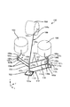
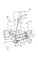
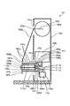
本発明の第1の実施形態について、図1〜図4を用いて説明する。図1及び図2に示すように、パラレルリンクロボット100は、ケース101と、出力部材102と、複数のモータ104、105、108、110と、複数のリンク機構106、107、109、112と、を有する。第1モータ104は第1アクチュエータに、第2モータ105は第2アクチュエータに、第3モータ108は第3アクチュエータに、第4モータ110は第4アクチュエータに、それぞれ相当する。また、106は第1リンク機構に、107は第2リンク機構に、109は第3リンク機構に、112は第4リンク機構に、それぞれ相当する。
<First Embodiment>
A first embodiment of the present invention will be described with reference to FIGS. As shown in FIGS. 1 and 2, the parallel link robot 100 includes a case 101, an output member 102, a plurality of motors 104, 105, 108, 110, a plurality of link mechanisms 106, 107, 109, 112, Have The first motor 104 corresponds to the first actuator, the second motor 105 corresponds to the second actuator, the third motor 108 corresponds to the third actuator, and the fourth motor 110 corresponds to the fourth actuator. Further, 106 corresponds to the first link mechanism, 107 corresponds to the second link mechanism, 109 corresponds to the third link mechanism, and 112 corresponds to the fourth link mechanism.

[ケース]
ケース101内には、第1モータ104、第2モータ105、第3モータ108、第4モータ110を、それぞれの可動部が出力部材側に突出しないように収納する。ケース101はベース部材を兼ねており、複数のモータ104、105、108、110が、ケース101内のそれぞれの所定の位置に直接又は取付部材などを介して固定されている。
[Case]
In the case 101, the first motor 104, the second motor 105, the third motor 108, and the fourth motor 110 are accommodated so that the respective movable parts do not protrude toward the output member side. The case 101 also serves as a base member, and a plurality of motors 104, 105, 108, and 110 are fixed to respective predetermined positions in the case 101 directly or via attachment members.

また、各モータの駆動力は後述するリンク機構106、107、109、112を介して出力部材102に伝達するようにして、各モータにより駆動されて各リンク機構を駆動する可動部がケース101内に収まるようにしている。更に、ケース101の複数個所に開口部101aを設け、開口部101aを介して、各モータにより各リンク機構をそれぞれ駆動可能としている。なお、ケース101は一体の構成でなくてもよく、複数の筐体を連結させた構成でもよい。   The driving force of each motor is transmitted to the output member 102 via link mechanisms 106, 107, 109, and 112, which will be described later, and a movable part that is driven by each motor and drives each link mechanism is provided in the case 101. To fit in. Furthermore, openings 101a are provided at a plurality of locations of the case 101, and each link mechanism can be driven by each motor via the openings 101a. Note that the case 101 does not have to be an integral configuration, and may have a configuration in which a plurality of casings are connected.

[出力部材]
出力部材102は、ワークの移動や加工などを行う工具を取り付けるものである。このような出力部材102は、z軸方向に略平行に配置された出力軸103の先端部(下端部)に結合されている。後述するように、出力部材102は、出力軸103を回転軸として回転可能である。言い換えれば、出力部材102は、回転軸がz軸と略平行である。本実施形態では、z軸方向を鉛直方向としている。
[Output member]
The output member 102 is for attaching a tool for moving or machining a workpiece. Such an output member 102 is coupled to the distal end portion (lower end portion) of the output shaft 103 disposed substantially parallel to the z-axis direction. As will be described later, the output member 102 can rotate about the output shaft 103 as a rotation axis. In other words, the output member 102 has a rotation axis substantially parallel to the z-axis. In the present embodiment, the z-axis direction is the vertical direction.

なお、出力軸103は軸状の形態を有することが好適であるが、実際に軸状の形態を有さなくても良い。後述するように、平行リンク等のリンク部材が結合されるジョイント部が略直線上に並べられれば良く、本発明の出力軸はこのような場合も含むものとする。   Note that the output shaft 103 preferably has an axial shape, but may not actually have an axial shape. As will be described later, it is only necessary that joint portions to which link members such as parallel links are coupled are arranged on a substantially straight line, and the output shaft of the present invention includes such a case.

[第1モータ及び第2モータ]
第1モータ104及び第2モータ105は、それぞれが出力部材102を概ねxy平面に沿って(水平方向に)移動させるための駆動源となる回転型アクチュエータの一例である。なお、厳密に言えば第3モータ108を停止している場合は、第1モータ104及び第2モータ105によって出力部材102は仮想的な球面上を移動することになる。このような第1モータ104及び第2モータ105は、回転軸の方向がz軸方向(鉛直方向)に略平行に配置されている。そして、第1モータ104の回転軸に第1アーム104aを、第2モータ105の回転軸に第2アーム105aをそれぞれ固定している。これら第1アーム104a及び第2アーム105aは、xy平面(水平面)に略平行に配置される。したがって、第1アーム104aは第1モータ104の駆動により、第2アーム105aは第2モータ105により、それぞれ略水平方向に揺動する。
[First motor and second motor]
Each of the first motor 104 and the second motor 105 is an example of a rotary actuator serving as a drive source for moving the output member 102 substantially along the xy plane (in the horizontal direction). Strictly speaking, when the third motor 108 is stopped, the output member 102 moves on a virtual spherical surface by the first motor 104 and the second motor 105. The first motor 104 and the second motor 105 are arranged so that the direction of the rotation axis is substantially parallel to the z-axis direction (vertical direction). The first arm 104 a is fixed to the rotating shaft of the first motor 104, and the second arm 105 a is fixed to the rotating shaft of the second motor 105. The first arm 104a and the second arm 105a are disposed substantially parallel to the xy plane (horizontal plane). Therefore, the first arm 104a is swung in the substantially horizontal direction by the drive of the first motor 104, and the second arm 105a is swung in the substantially horizontal direction by the second motor 105, respectively.

[第3モータ]
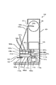
第3モータ108は、出力部材102を概ねz軸方向に移動させるための駆動源となる回転型アクチュエータの一例である。このような第3モータ108は、回転軸の方向がz軸と直交する直交軸(水平軸)と略平行となるように配置されている。そして、第3モータ108の回転軸に、回動腕部である第3アーム108aを固定している。この第3アーム108aは、第3モータ108の回転軸に直交する平面(水平面に略直交する平面)上に配置される。したがって、第3アーム108aは第3モータ108の駆動により、第3モータ108の回転軸を中心として、この回転軸に直交する平面に沿って揺動し、第3アーム108aの先端部に結合された後述の第3リンク機構109を介して、出力部材102を概ねz軸方向に移動することができる。厳密に言えば、第1モータ104と第2モータ105を停止している場合は、第3モータ108の駆動により出力部材102は仮想的な円弧上を移動することになる。なお、第3モータ108を駆動方向がz軸に略平行なリニアアクチュエータに変更してもよい。
[Third motor]
The third motor 108 is an example of a rotary actuator that serves as a drive source for moving the output member 102 in the z-axis direction. The third motor 108 is arranged so that the direction of the rotation axis is substantially parallel to an orthogonal axis (horizontal axis) orthogonal to the z axis. A third arm 108 a that is a rotating arm portion is fixed to the rotation shaft of the third motor 108. The third arm 108a is disposed on a plane orthogonal to the rotation axis of the third motor 108 (a plane substantially orthogonal to the horizontal plane). Therefore, the third arm 108a swings about a rotation axis of the third motor 108 along a plane orthogonal to the rotation axis by the driving of the third motor 108, and is coupled to the tip of the third arm 108a. Further, the output member 102 can be moved substantially in the z-axis direction via a third link mechanism 109 described later. Strictly speaking, when the first motor 104 and the second motor 105 are stopped, the output member 102 moves on a virtual arc by driving the third motor 108. Note that the third motor 108 may be changed to a linear actuator whose driving direction is substantially parallel to the z-axis.

[第4モータ]
第4モータ110は、出力部材102をz軸回り(鉛直軸回り)に回動させるための駆動源となる回転型アクチュエータの一例である。このような第4モータは、回転軸の方向がz軸方向(鉛直方向)に略平行となるように配置されている。そして、第4モータ110の回転軸に第4アーム110aを固定している。この第4アーム110aは、xy平面(水平面)に略平行に配置される。したがって、第4アーム110aは第4モータ110の駆動により略水平方向に揺動する。
[Fourth motor]
The fourth motor 110 is an example of a rotary actuator serving as a drive source for rotating the output member 102 about the z axis (about the vertical axis). Such a 4th motor is arrange | positioned so that the direction of a rotating shaft may become substantially parallel to a z-axis direction (vertical direction). The fourth arm 110 a is fixed to the rotation shaft of the fourth motor 110. The fourth arm 110a is disposed substantially parallel to the xy plane (horizontal plane). Accordingly, the fourth arm 110 a swings in a substantially horizontal direction by driving the fourth motor 110.

なお、上述の説明では、第1、第2、第3、第4アクチュエータは、それぞれ電動の回転型アクチュエータ(モータ)としたが、例えば、直線方向に駆動するリニア(直動)アクチュエータとしても良い。この場合、第1、第2、第4アクチュエータは、アクチュエータの駆動により直線方向に移動する移動子が、xy平面(水平面)に略平行に移動するようにする。また、第3アクチュエータは、移動子がz軸方向(鉛直方向)に略平行に移動するようにする。また、これら回転型、リニア型等のアクチュエータは、サーボモータ、ステッピングモータ、超音波モータ等の電動アクチュエータ以外に、油圧などの他の動力により駆動されるものでもよい。   In the above description, each of the first, second, third, and fourth actuators is an electric rotary actuator (motor). However, for example, a linear (direct acting) actuator that drives in a linear direction may be used. . In this case, the first, second, and fourth actuators cause the mover that moves in the linear direction by driving the actuator to move substantially parallel to the xy plane (horizontal plane). The third actuator causes the moving element to move substantially parallel to the z-axis direction (vertical direction). Further, these rotary type and linear type actuators may be driven by other powers such as hydraulic pressure in addition to electric actuators such as servo motors, stepping motors, and ultrasonic motors.

[第1リンク機構及び第2リンク機構]
第1リンク機構106及び第2リンク機構107は、出力軸103と第1モータ104の第1アーム104aとの間、及び、出力軸103と第2モータ105の第2アーム105aとの間に、それぞれ設けられている。そして、後述するように出力部材102の出力軸(回転軸)103をz軸に略平行に保つように保持しつつ、第1モータ104及び第2モータ105の駆動により出力部材102をz軸に交差する方向に移動可能としている。
[First link mechanism and second link mechanism]
The first link mechanism 106 and the second link mechanism 107 are provided between the output shaft 103 and the first arm 104a of the first motor 104, and between the output shaft 103 and the second arm 105a of the second motor 105. Each is provided. As will be described later, the output member 102 is moved to the z-axis by driving the first motor 104 and the second motor 105 while holding the output shaft (rotating shaft) 103 of the output member 102 so as to be substantially parallel to the z-axis. It can move in the intersecting direction.

出力軸103とz軸との略平行を保つために、第1リンク機構106は、第1軸104bと、出力軸103と、複数の第1リンク部材である2本の第1リンクバー106aとを有する。また、第2リンク機構107は、第2軸105bと、出力軸103と、複数の第2リンク部材である2本の第2リンクバー107aとを有する。なお、第1リンクバー106aと第2リンクバー107aとは、それぞれ3本以上としても良い。   In order to keep the output shaft 103 and the z-axis substantially parallel, the first link mechanism 106 includes a first shaft 104b, an output shaft 103, and two first link bars 106a that are a plurality of first link members. Have The second link mechanism 107 includes a second shaft 105b, an output shaft 103, and two second link bars 107a that are a plurality of second link members. The first link bar 106a and the second link bar 107a may each be three or more.

第1軸104bは、出力軸103と平行に配置され、第1モータ104の駆動によりxy平面に沿って移動させられる。また、第2軸105bは、出力軸103と平行に配置され、第2モータ105の駆動によりxy平面に沿って移動させられる。このために、第1軸104bの中間部は、軸受104cを介して第1アーム104aに、第2軸105bの中間部は、軸受105cを介して第2アーム105aに、それぞれ接続されている。また、第1軸104bは第1アーム104aに、第2軸105bは第2アーム105aに、それぞれz軸に対して略平行を保つように支持されている。   The first shaft 104 b is disposed in parallel with the output shaft 103 and is moved along the xy plane by driving the first motor 104. The second shaft 105 b is disposed in parallel with the output shaft 103 and is moved along the xy plane by driving the second motor 105. For this purpose, the intermediate portion of the first shaft 104b is connected to the first arm 104a via the bearing 104c, and the intermediate portion of the second shaft 105b is connected to the second arm 105a via the bearing 105c. The first shaft 104b is supported by the first arm 104a, and the second shaft 105b is supported by the second arm 105a so as to be substantially parallel to the z-axis.

なお、第1軸104b、第2軸105bは軸状の形態を有することが好適であるが、実際に軸状の形態を有さなくてもよく、平行リンクのリンク部材であるリンクバーが結合されるジョイントをz軸(鉛直線)に略平行な直線上に並べてあればよい。また、第1軸104b、第2軸105bはそれぞれ第1モータ104の回転軸、第2モータ105の回転軸に対して略平行であることが好ましい。   The first shaft 104b and the second shaft 105b preferably have an axial shape. However, the first shaft 104b and the second shaft 105b may not actually have an axial shape, and a link bar that is a link member of a parallel link is coupled. It is only necessary that the joints to be arranged are arranged on a straight line substantially parallel to the z-axis (vertical line). The first shaft 104b and the second shaft 105b are preferably substantially parallel to the rotation axis of the first motor 104 and the rotation axis of the second motor 105, respectively.

第1リンク機構106の2本の第1リンクバー106aは、同じ長さを有し、互いに平行に配置された状態で、第1軸104bと出力軸103とを接続する。本実施形態では、第1軸104b、出力部材102に固定の出力軸103、2本の第1リンクバー106aで平行リンク機構を構成している。このため、出力部材102の位置に拘らず、第1軸104bと出力軸103との平行、2本の第1リンクバー106aの平行がそれぞれ保持される。   The two first link bars 106a of the first link mechanism 106 have the same length and connect the first shaft 104b and the output shaft 103 in a state of being arranged in parallel to each other. In the present embodiment, the first shaft 104b, the output shaft 103 fixed to the output member 102, and the two first link bars 106a constitute a parallel link mechanism. Therefore, regardless of the position of the output member 102, the parallelism between the first shaft 104b and the output shaft 103 is maintained, and the parallelism between the two first link bars 106a is maintained.

第2リンク機構107の2本の第2リンクバー107aは、同じ長さを有し、互いに平行に配置された状態で、第2軸105bと出力軸103とを接続する。本実施形態では、第2軸105b、出力部材102に固定の出力軸103、2本の第2リンクバー107aで平行リンク機構を構成している。このため、出力部材102の位置に拘らず、第2軸105bと出力軸103との平行、2本の第2リンクバー107aの平行がそれぞれ保持される。   The two second link bars 107a of the second link mechanism 107 have the same length and connect the second shaft 105b and the output shaft 103 in a state of being arranged in parallel to each other. In the present embodiment, a parallel link mechanism is configured by the second shaft 105b, the output shaft 103 fixed to the output member 102, and the two second link bars 107a. Therefore, regardless of the position of the output member 102, the parallelism between the second shaft 105b and the output shaft 103 is maintained, and the parallelism between the two second link bars 107a is maintained.

また、本実施形態の場合、出力部材102がx、y、z軸の何れの方向にも移動できるように、第1リンク機構106及び第2リンク機構107の各ジョイント部を構成している。まず、第1リンク機構106は、出力軸103と2本の第1リンクバー106aの一端部とを、複数の(2個の)第1出力側ジョイント部106bによりそれぞれ連結している。また、第1軸104bと2本の第1リンクバー106aの他端部とを、複数の(2個の)第1駆動側ジョイント部106cによりそれぞれ連結している。   In the case of this embodiment, the joint portions of the first link mechanism 106 and the second link mechanism 107 are configured so that the output member 102 can move in any direction of the x, y, and z axes. First, the first link mechanism 106 connects the output shaft 103 and one end portions of the two first link bars 106a by a plurality of (two) first output side joint portions 106b. Further, the first shaft 104b and the other end portions of the two first link bars 106a are respectively connected by a plurality of (two) first drive side joint portions 106c.

第2リンク機構107は、出力軸103と2本の第2リンクバー107aの一端部とを、複数の(2個の)第2出力側ジョイント部107bによりそれぞれ連結している。また、第2軸105bと2本の第2リンクバー107aの他端部とを、複数の(2個の)第2駆動側ジョイント部107cによりそれぞれ連結している。   The second link mechanism 107 connects the output shaft 103 and one end portions of the two second link bars 107a by a plurality of (two) second output side joint portions 107b. Further, the second shaft 105b and the other end portions of the two second link bars 107a are respectively connected by a plurality of (two) second drive side joint portions 107c.

2個の第1出力側ジョイント部106bは、少なくとも、出力軸103に対して第1リンクバー106aを、出力軸回りの回動、及び、出力軸及び第1リンクバー106aの配設方向に直交する直交軸を中心として回動自在である。2個の第2出力側ジョイント部107bは、少なくとも、出力軸103に対する第2リンクバー107aの、出力軸回りの回動、及び、出力軸及び第2リンクバー107aの配設方向に直交する直交軸を中心とした回動を可能とする。即ち、第1出力側ジョイント部106b及び第2出力側ジョイント部107bは、少なくとも2自由度を有する。   The two first output-side joint portions 106b are at least perpendicular to the rotation direction of the first link bar 106a relative to the output shaft 103 and the arrangement direction of the output shaft and the first link bar 106a. It is freely rotatable around an orthogonal axis. The two second output side joint portions 107b are orthogonal to at least the rotation of the second link bar 107a relative to the output shaft 103 around the output shaft and the arrangement direction of the output shaft and the second link bar 107a. Allows rotation around the axis. That is, the first output side joint portion 106b and the second output side joint portion 107b have at least two degrees of freedom.

2個の第1駆動側ジョイント部106cは、少なくとも、第1軸104bに対して第1リンクバー106aを、第1軸104b及び第1リンクバー106aの配設方向に直交する直交軸を中心として回動自在である。2個の第2駆動側ジョイント部107cは、少なくとも、第2軸105bに対する第2リンクバー107aの、第2軸105b及び第2リンクバー107aの配設方向に直交する直交軸を中心とした回動を可能とする。即ち、第1駆動側ジョイント部106c及び第2駆動側ジョイント部107cは、少なくとも1自由度を有する。   The two first drive side joint portions 106c center at least on the first link bar 106a with respect to the first shaft 104b and on an orthogonal axis orthogonal to the arrangement direction of the first shaft 104b and the first link bar 106a. It can rotate freely. The two second drive side joint portions 107c are at least a rotation of the second link bar 107a with respect to the second shaft 105b about an orthogonal axis orthogonal to the arrangement direction of the second shaft 105b and the second link bar 107a. To enable movement. That is, the first drive side joint part 106c and the second drive side joint part 107c have at least one degree of freedom.

なお、本実施形態では、第1軸104bが第1アーム104aに軸受104cを介して支持されているため、第1軸104b自体が第1アーム104aに対して回転する。また、第2軸105bが第2アーム105aに軸受105cを介して支持されているため、第2軸105b自体が第2アーム105aに対して回転する。   In the present embodiment, since the first shaft 104b is supported by the first arm 104a via the bearing 104c, the first shaft 104b itself rotates with respect to the first arm 104a. Further, since the second shaft 105b is supported by the second arm 105a via the bearing 105c, the second shaft 105b itself rotates with respect to the second arm 105a.

[出力部材の出力軸に交差する方向への移動]
上述のように、第1モータ104と出力部材102との間、及び、第2モータ105と出力部材102との間に、それぞれ平行リンク機構を設け、これら2個のモータにより出力部材102を出力軸に交差する方向に移動させている。このとき、第1軸104b及び第2軸105bはz軸方向に対して略平行を保ちながら移動される。このため、第1モータ104及び第2モータ105の駆動により、出力部材102の回転軸(出力軸103)のz軸方向(鉛直方向)に対する略平行の姿勢を保ちながら、この出力部材102を出力軸に交差する概ね水平の方向に移動させることができる。
[Movement of output member in direction crossing output axis]
As described above, a parallel link mechanism is provided between the first motor 104 and the output member 102 and between the second motor 105 and the output member 102, and the output member 102 is output by these two motors. It is moved in the direction that intersects the axis. At this time, the first shaft 104b and the second shaft 105b are moved while being substantially parallel to the z-axis direction. Therefore, by driving the first motor 104 and the second motor 105, the output member 102 is output while maintaining a substantially parallel posture with respect to the z-axis direction (vertical direction) of the rotation shaft (output shaft 103) of the output member 102. It can be moved in a generally horizontal direction intersecting the axis.

また、本実施形態の場合、出力軸103側の2個の第1出力側ジョイント部106bと、出力軸103側の2個の第2出力側ジョイント部107bとが、z軸と略平行な同一軸上、即ち出力軸103上に配置されている。これにより、第1モータ104の制御による出力軸103の位置と、第2モータ105による出力軸103の位置とが必ず一致するため、両モータの制御量の差により生じる出力軸103の位置決め誤差を低減できる。なお、複数の第1出力側ジョイント部106bを結ぶ直線と、複数の第2出力側ジョイント部107bを結ぶ直線とを実質的に一致させていればよく、構造上の要求からわずかにずらして配置してもよい。   In the case of this embodiment, the two first output side joint portions 106b on the output shaft 103 side and the two second output side joint portions 107b on the output shaft 103 side are the same substantially parallel to the z axis. It is arranged on the shaft, that is, on the output shaft 103. As a result, the position of the output shaft 103 by the control of the first motor 104 and the position of the output shaft 103 by the second motor 105 always coincide with each other. Can be reduced. The straight lines connecting the plurality of first output side joint portions 106b and the straight lines connecting the plurality of second output side joint portions 107b may be substantially matched, and are slightly shifted from structural requirements. May be.

更に、2個の第1出力側ジョイント部106bを結ぶ線分の中点と、2個の第2出力側ジョイント部107bを結ぶ線分の中点とが略一致するように、2本の第1リンクバー106a及び2本の第2リンクバー107aをそれぞれ配置している。図示の例では、2個の第2出力側ジョイント部107bの間に2個の第1出力側ジョイント部106bを配置している。そして、隣接する第1出力側ジョイント部106bと第2出力側ジョイント部107bの上側の一対の間隔と下側の一対の間隔とを、互いに同じとしている。   Furthermore, the two middle points of the line connecting the two first output side joint parts 106b and the middle point of the line segment connecting the two second output side joint parts 107b substantially coincide with each other. One link bar 106a and two second link bars 107a are arranged. In the illustrated example, two first output side joint portions 106b are arranged between two second output side joint portions 107b. Then, the upper pair of intervals and the lower pair of intervals between the adjacent first output side joint part 106b and second output side joint part 107b are the same.

これにより、第1モータ104の駆動により出力軸103を移動させる力と、第2モータの駆動により出力軸103を移動させる力とを釣り合わせ易くできる。即ち、出力軸103を2個のモータにより出力軸103に交差する方向に移動させても、出力軸103にバランス良く力を作用させることができる。この結果、出力軸103の移動の際に出力軸103に傾くような力が作用せず、位置決め制度を向上させられる。   Thereby, it is possible to easily balance the force for moving the output shaft 103 by driving the first motor 104 and the force for moving the output shaft 103 by driving the second motor. That is, even if the output shaft 103 is moved in the direction intersecting the output shaft 103 by two motors, a force can be applied to the output shaft 103 with a good balance. As a result, a force that tilts the output shaft 103 does not act when the output shaft 103 moves, and the positioning system can be improved.

[第3リンク機構]
第3リンク機構109は、出力部材102の出力軸103と第3モータ108の第3アーム108aとの間に設けられ、第3モータ108の駆動により出力部材102を概ねz軸方向に移動可能としている。このような第3リンク機構109は、回動腕部(可動部材)である第3アーム108aと、第3リンク部材である第3リンクバー109aと、出力軸103とにより構成される。
[Third link mechanism]
The third link mechanism 109 is provided between the output shaft 103 of the output member 102 and the third arm 108a of the third motor 108, and the output member 102 can be moved substantially in the z-axis direction by driving the third motor 108. Yes. Such a third link mechanism 109 includes a third arm 108 a that is a rotating arm (movable member), a third link bar 109 a that is a third link member, and an output shaft 103.

第3リンクバー109aは、一端部を出力軸103の上端部に第3出力側ジョイント部109bにより連結され、他端部を第3アーム108aの先端部に第3駆動側ジョイント部109cにより連結されている。このうちの第3出力側ジョイント部109bは、少なくとも、出力軸103に対する第3リンクバー109aの、出力軸103回りの回動、及び、出力軸及び第3リンクバー109aの配設方向に直交する直交軸を中心とした回動を可能とする。即ち、第3出力側ジョイント部109bは、少なくとも2自由度を有する。   The third link bar 109a has one end connected to the upper end of the output shaft 103 by a third output side joint 109b, and the other end connected to the tip of the third arm 108a by a third drive side joint 109c. ing. Among these, the third output side joint portion 109b is orthogonal to at least the rotation of the third link bar 109a with respect to the output shaft 103 around the output shaft 103 and the arrangement direction of the output shaft and the third link bar 109a. Allows rotation around an orthogonal axis. That is, the third output side joint portion 109b has at least two degrees of freedom.

一方、第3駆動側ジョイント部109cは、少なくとも、第3アーム108aに対して第3リンクバー109aを、次の3つの自由度を有するように連結する。即ち、第3アーム108aの配設方向回りの回動と、第3アーム108aの配設方向及び第3リンクバー109aの配設方向に直交する直交軸を中心とした回動と、第3リンクバー109a(第3リンク部材自身)の配設方向回りの回動とを可能とする。第3アーム108aの回動中心軸は、第3モータ108の回転軸である。   On the other hand, the third drive side joint portion 109c connects the third link bar 109a to at least the third arm 108a so as to have the following three degrees of freedom. That is, rotation about the arrangement direction of the third arm 108a, rotation about the orthogonal axis orthogonal to the arrangement direction of the third arm 108a and the arrangement direction of the third link bar 109a, and the third link The bar 109a (the third link member itself) can be rotated around the arrangement direction. The rotation center axis of the third arm 108 a is the rotation axis of the third motor 108.

なお、第3モータ108を移動子の移動方向がz軸に略平行なリニアアクチュエータに置き換えた場合、このリニアアクチュエータの移動子と第3リンクバー109aの他端部とを結合する第3駆動側ジョイント部は、2自由度とすることができる。例えば、移動子の移動方向に略平行な軸回りの回動の自由度と、この軸と第3リンクバー109aの配設方向に直交する軸回りの回動の自由度を有するジョイントが好適である。   When the third motor 108 is replaced with a linear actuator in which the moving direction of the moving element is substantially parallel to the z-axis, the third driving side that couples the moving element of the linear actuator and the other end of the third link bar 109a. The joint portion can have two degrees of freedom. For example, a joint having a degree of freedom of rotation about an axis substantially parallel to the moving direction of the moving element and a degree of freedom of rotation about an axis orthogonal to the arrangement direction of this axis and the third link bar 109a is suitable. is there.

なお、図1及び図2に丸印で示した2自由度のジョイント部106b、107b、109b等としては、例えば図3に例示する構造のジョイントを適用できる。図3のジョイントは、矢印Aに示すような支持軸の周りに1回転以上回転する自由度と、矢印Bに示すような支持軸に略直角な軸周りに所定の振れ角度範囲内で回動する自由度を有する。後述する他の2自由度のジョイントも、この図3に例示する構造を有するものが好適である。このような2自由度のジョイントを用いれば、リンクバーの配設方向回りの回転の自由度を有さないので、平行リンク機構のねじれを防止することができる。   For example, a joint having a structure illustrated in FIG. 3 can be applied as the joint sections 106b, 107b, and 109b having two degrees of freedom indicated by circles in FIGS. The joint of FIG. 3 rotates within a predetermined deflection angle range around an axis substantially perpendicular to the support shaft as shown by the arrow B and a degree of freedom of rotating around the support shaft as shown by the arrow A. Have the freedom to The other two-degree-of-freedom joint to be described later preferably has the structure illustrated in FIG. If such a two-degree-of-freedom joint is used, the parallel link mechanism can be prevented from being twisted because there is no degree of freedom of rotation around the link bar arrangement direction.

第3駆動側ジョイント部109cとしては、例えば上述の2自由度のジョイントに第3リンクバー109aの配設方向回りの回転の自由度を加え3自由度としたものが好適である。或いは、剛体の第3リンクバー109aを用いる代わりにワイヤや樹脂バーや途中に軸受を有するリンクバー等のねじれを許容するリンク部材を使用し、第3駆動側ジョイント部109cを2自由度にしても良い。或いは、第3リンクバー109aの第3駆動側ジョイント部109cを2自由度とし、第3出力側ジョイント部109bを3自由度にしても良い。   As the third drive side joint portion 109c, for example, a joint having three degrees of freedom by adding a degree of freedom of rotation around the arrangement direction of the third link bar 109a to the above-described joint of two degrees of freedom is preferable. Alternatively, instead of using the rigid third link bar 109a, a link member that allows torsion such as a wire, a resin bar, or a link bar having a bearing in the middle is used, and the third drive side joint portion 109c is made to have two degrees of freedom. Also good. Alternatively, the third drive side joint portion 109c of the third link bar 109a may have two degrees of freedom, and the third output side joint portion 109b may have three degrees of freedom.

[出力部材の上下移動]
第3モータ108を駆動すると、第3アーム108aの先端が水平面に略直交する平面に沿って揺動し(第3アーム108aの運動により)、この第3アーム108aの先端に第3リンクバー109aを介して接続された出力部材102が概ね鉛直方向に移動する。厳密には第3アーム108aのみ駆動すると出力部材102は仮想的な円弧上を移動する。第1モータ104及び第2モータ105の駆動による、出力軸103に交差する概ね水平の方向への出力軸103の移動とともに、第3モータ108を駆動すれば、出力軸103の水平方向と鉛直方向への移動が可能となる。したがって、第1モータ104及び第2モータ105の駆動による出力部材102のz軸に交差する方向への移動に対応させて、第3モータ108の駆動により出力部材102をz軸に概ね平行な方向へ移動させることにより、xyz空間内で出力部材102を位置決め可能である。
[Up-down movement of output member]
When the third motor 108 is driven, the tip of the third arm 108a swings along a plane substantially orthogonal to the horizontal plane (by the movement of the third arm 108a), and the third link bar 109a is placed on the tip of the third arm 108a. The output member 102 connected via the head moves substantially in the vertical direction. Strictly speaking, when only the third arm 108a is driven, the output member 102 moves on a virtual arc. When the third motor 108 is driven along with the movement of the output shaft 103 in the substantially horizontal direction intersecting the output shaft 103 by driving the first motor 104 and the second motor 105, the horizontal direction and the vertical direction of the output shaft 103 are driven. Can be moved to. Therefore, in response to the movement of the output member 102 in the direction intersecting the z axis by driving the first motor 104 and the second motor 105, the output member 102 is driven in a direction substantially parallel to the z axis by driving the third motor 108. The output member 102 can be positioned in the xyz space.

また、前述のように、第1モータ104と出力部材102との間、及び、第2モータ105と出力部材102との間に、それぞれ平行リンク機構を設けている。このため、出力部材102の水平方向及び鉛直方向の移動に拘らず、出力軸103を鉛直方向と略平行な状態に維持できる。   Further, as described above, parallel link mechanisms are provided between the first motor 104 and the output member 102 and between the second motor 105 and the output member 102, respectively. For this reason, regardless of the movement of the output member 102 in the horizontal direction and the vertical direction, the output shaft 103 can be maintained in a state substantially parallel to the vertical direction.

また、第3モータ108の駆動により、出力軸103を鉛直上下方向に移動すると、第1リンクバー106aと第2リンクバー107aは水平から傾斜する。このため、出力軸103の3次元空間内の移動位置は、第1リンクバー106a、第2リンクバー107a、第3リンクバー109aの傾斜を考慮して、第1、第2、第3モータ104、105、108の駆動量(回転角度)から幾何学的に算出する。   Further, when the output shaft 103 is moved in the vertical vertical direction by driving the third motor 108, the first link bar 106a and the second link bar 107a are inclined from the horizontal. For this reason, the movement position of the output shaft 103 in the three-dimensional space takes into account the inclination of the first link bar 106a, the second link bar 107a, and the third link bar 109a, and the first, second, and third motors 104. , 105, and 108 are geometrically calculated from the driving amounts (rotation angles).

なお、第1、第2モータ104、105の駆動量から概略の位置を算出し、それを第3モータ108の駆動量に応じて補正することで、出力軸103のxyz空間内の正確な移動位置を算出するようにしても良い。また、算出値を予め数値テーブルに格納しておき、目標とする移動位置に基づいて第1、第2、第3モータ104、105、108の駆動量をこの数値テーブルから求めることが好適である。また、移動位置から第1、第2、第3モータ104、105、108の駆動量を逆算する算出式を用いても良い。以上のようにして出力軸103の移動位置と第1、第2、第3モータ104、105、108の駆動量を関係付けることで、出力軸103に固定の出力部材102の3次元位置の位置決めが可能となる。   The approximate position is calculated from the driving amounts of the first and second motors 104 and 105, and is corrected according to the driving amount of the third motor 108, so that the output shaft 103 can be accurately moved in the xyz space. The position may be calculated. It is also preferable to store the calculated values in a numerical table in advance and obtain the driving amounts of the first, second, and third motors 104, 105, and 108 from the numerical table based on the target movement positions. . Also, a calculation formula that reversely calculates the driving amounts of the first, second, and third motors 104, 105, and 108 from the movement position may be used. By associating the moving position of the output shaft 103 with the driving amounts of the first, second, and third motors 104, 105, and 108 as described above, the three-dimensional position of the output member 102 fixed to the output shaft 103 is determined. Is possible.

また、第3リンクバー109aの出力軸103側の第3出力側ジョイント部109bは、上述のように出力軸103の上端部に設けられている。したがって、本実施形態の場合、この第3出力側ジョイント部109bと、2個の第1出力側ジョイント部106b及び2個の第2出力側ジョイント部107bとが、z軸と略平行な同一軸上(出力軸103上)に配置される。これにより、第1モータ104によって出力軸103に対して力を作用させる位置と、第2モータ105によって出力軸103に対して力を作用させる位置と、第3モータ108によって出力軸103に対して力を作用させる位置とが上方から見ていつでも一致する。このため、3つのモータを協働させて行う出力軸103の位置決めの誤差を低減できる。なお、第3リンクバー109aの第3出力側ジョイント部109bを設ける位置は、出力軸103の上端部とすることが他のリンクバーとの干渉を防止するために好適であるが、これに限定するものではない。例えば、第3リンクバー109aの第3出力側ジョイント部109bを設ける位置を、出力軸103の中央付近にしてもよい。このようにすれば、他のリンクバーから作用する力と第3リンクバー109aから作用する力とのバランスが良好になり、出力軸103の傾きを防止できる。   Further, the third output side joint portion 109b on the output shaft 103 side of the third link bar 109a is provided at the upper end portion of the output shaft 103 as described above. Therefore, in the case of the present embodiment, the third output side joint portion 109b, the two first output side joint portions 106b, and the two second output side joint portions 107b have the same axis substantially parallel to the z axis. Arranged above (on the output shaft 103). Accordingly, a position where a force is applied to the output shaft 103 by the first motor 104, a position where a force is applied to the output shaft 103 by the second motor 105, and a position where the force is applied to the output shaft 103 by the third motor 108. The position where the force is applied always matches the position as viewed from above. For this reason, the positioning error of the output shaft 103 performed by cooperating the three motors can be reduced. The position where the third output side joint portion 109b of the third link bar 109a is provided is preferably the upper end portion of the output shaft 103 in order to prevent interference with other link bars, but is not limited thereto. Not what you want. For example, the position where the third output side joint portion 109b of the third link bar 109a is provided may be near the center of the output shaft 103. By doing so, the balance between the force acting from the other link bar and the force acting from the third link bar 109a becomes good, and the inclination of the output shaft 103 can be prevented.

[回転伝達手段]
また、本実施形態の場合、第2モータ105により水平方向に移動させられる第2軸105bの下端部に、軸受105dを介して回転部材であるリンクアーム105eを回転自在に支持している。また、第4モータ110の駆動をリンクアーム105eに伝達する回転伝達手段111を有する。
[Rotation transmission means]
In the case of this embodiment, a link arm 105e, which is a rotating member, is rotatably supported via a bearing 105d at the lower end portion of the second shaft 105b that is moved in the horizontal direction by the second motor 105. Moreover, it has the rotation transmission means 111 which transmits the drive of the 4th motor 110 to the link arm 105e.

回転伝達手段111は、第4モータ110の第4アーム110aとリンクアーム105eとの間にリンクバー111aを設けてなる。リンクバー111aの一端部は、出力側ジョイント部111bによりリンクアーム105eに連結され、リンクバー111aの他端部は、駆動側ジョイント部111cにより第4アーム110aの先端部に連結されている。   The rotation transmission means 111 is provided with a link bar 111a between the fourth arm 110a of the fourth motor 110 and the link arm 105e. One end portion of the link bar 111a is connected to the link arm 105e by the output side joint portion 111b, and the other end portion of the link bar 111a is connected to the distal end portion of the fourth arm 110a by the drive side joint portion 111c.

出力側ジョイント部111bは、少なくとも、リンクアーム105eに対してリンクバー111aを、z軸に略平行な軸回りに回動可能とする自由度を有している。また、駆動側ジョイント部111cは、少なくとも、第4アーム110aに対してリンクバー111aを、z軸に略平行な軸回りに回動可能とする自由度を有している。即ち、何れのジョイント部111b、111cは、少なくとも1自由度を有するものであれば良い。但し、本実施形態の場合、部品の共通化を図るため、ジョイント部111b、111cは、第1出力側ジョイント部106bなどと同様の2自由度を有するものを使用している。   The output side joint portion 111b has at least a degree of freedom that allows the link bar 111a to rotate about an axis substantially parallel to the z axis with respect to the link arm 105e. Further, the drive side joint portion 111c has a degree of freedom that allows the link bar 111a to rotate about an axis substantially parallel to the z axis with respect to at least the fourth arm 110a. That is, any of the joint portions 111b and 111c may have at least one degree of freedom. However, in the present embodiment, in order to share parts, the joint portions 111b and 111c have the same two degrees of freedom as the first output side joint portion 106b and the like.

なお、回転伝達手段111は、上述のようなリンク機構以外の構成としても良い。例えば、第4モータ110の第4アーム110aの代わりにこの第4アーム110aと同じ半径のプーリを設ける。一方、第2軸105bのリンクアーム105eの代わりにこのリンクアーム105eと同じ半径のプーリを設ける。そして、これら両プーリにベルトを掛け渡し、ベルトにより第4モータ110の回転を伝達する。   The rotation transmitting unit 111 may have a configuration other than the link mechanism as described above. For example, instead of the fourth arm 110a of the fourth motor 110, a pulley having the same radius as the fourth arm 110a is provided. On the other hand, a pulley having the same radius as that of the link arm 105e is provided instead of the link arm 105e of the second shaft 105b. Then, a belt is stretched between these pulleys, and the rotation of the fourth motor 110 is transmitted by the belt.

[第4リンク機構]
第4リンク機構112は、出力部材102の出力軸103と回転部材の駆動側腕部でもあるリンクアーム105eとの間に配置される。そして、出力部材102を鉛直軸回り(回転軸回り)に回転可能としている。このような第4リンク機構112は、出力軸103に設けられた出力側腕部である出力軸アーム103aと、リンクアーム105eとの間に、第4リンク部材である第4リンクバー112aを設けてなる。
[Fourth link mechanism]
The fourth link mechanism 112 is disposed between the output shaft 103 of the output member 102 and the link arm 105e that is also the driving side arm of the rotating member. The output member 102 can be rotated around the vertical axis (around the rotation axis). Such a fourth link mechanism 112 is provided with a fourth link bar 112a that is a fourth link member between the output shaft arm 103a that is an output side arm portion provided on the output shaft 103 and the link arm 105e. It becomes.

出力軸アーム103aは、出力軸103の下端寄りで出力部材102の上側に隣接する位置から水平方向に突出するように形成されている。また、出力軸アーム103aの水平方向の長さとリンクアーム105eの水平方向の長さを同じとしている。第4リンクバー112aの一端部は、第4出力側ジョイント部112bにより出力軸アーム103eに連結され、第4リンクバー112aの他端部は、第4駆動側ジョイント部112cによりリンクアーム105eに連結されている。   The output shaft arm 103 a is formed so as to protrude in the horizontal direction from a position adjacent to the upper side of the output member 102 near the lower end of the output shaft 103. Further, the horizontal length of the output shaft arm 103a and the horizontal length of the link arm 105e are the same. One end portion of the fourth link bar 112a is connected to the output shaft arm 103e by the fourth output side joint portion 112b, and the other end portion of the fourth link bar 112a is connected to the link arm 105e by the fourth drive side joint portion 112c. Has been.

第4出力側ジョイント部112bは、少なくとも、出力軸アーム103aに対する第4リンクバー112aの、z軸に略平行な軸回りの回動、及び、z軸に略平行な軸及び第4リンクバー112aの配設方向に直交する直交軸を中心とした回動を可能とする自由度を有している。また、第4駆動側ジョイント部112cは、少なくとも、リンクアーム105eに対する第4リンクバー112aの、z軸に略平行な軸回りの回動、及び、z軸に略平行な軸及び第4リンクバー112aの配設方向に直交する直交軸を中心とした回動を可能とする自由度を有している。即ち、第4出力側ジョイント部112b及び第4駆動側ジョイント部112cは、少なくとも2自由度を有する。   The fourth output side joint portion 112b includes at least a rotation of the fourth link bar 112a relative to the output shaft arm 103a about an axis substantially parallel to the z axis, and an axis substantially parallel to the z axis and the fourth link bar 112a. It has a degree of freedom that enables rotation about an orthogonal axis that is orthogonal to the arrangement direction. The fourth drive side joint portion 112c includes at least rotation of the fourth link bar 112a relative to the link arm 105e about an axis substantially parallel to the z axis, and an axis and fourth link bar substantially parallel to the z axis. There is a degree of freedom that enables rotation about an orthogonal axis orthogonal to the direction in which 112a is disposed. That is, the fourth output side joint portion 112b and the fourth drive side joint portion 112c have at least two degrees of freedom.

[各モータの配置]
また、本実施形態では、上述のように、出力部材102と、第1、第2、第3、第4モータ104、105、108、110との間に、それぞれ第1、第2、第3、第4リンク機構106、107、109、112を設けている。そして、第1、第2、第3、第4モータ104、105、108、110を、出力部材102の移動領域に対して水平方向に外れた位置に配置している。即ち、出力部材102がどの位置に移動しても、出力部材102が何れかのモータの鉛直方向下側に位置することはない。
[Arrangement of each motor]
Further, in the present embodiment, as described above, the first, second, and third between the output member 102 and the first, second, third, and fourth motors 104, 105, 108, and 110, respectively. The fourth link mechanisms 106, 107, 109, 112 are provided. Then, the first, second, third, and fourth motors 104, 105, 108, and 110 are disposed at positions that deviate in the horizontal direction with respect to the moving region of the output member 102. That is, no matter which position the output member 102 moves to, the output member 102 will not be positioned below the vertical direction of any motor.

特に、第1モータ104と第2モータ105とは、次のような関係を満たすように配置される。即ち装置の上方から眺めた場合に、第1モータ104の中心(回転軸)と出力部材102の中心(出力軸103)とを結ぶ線分と、第2モータ105の中心(回転軸)と出力軸103とを結ぶ線分との成す角度が、0°よりも大きく且つ180°よりも小さくなるように配置される。言い換えれば、第1モータ104と第2モータ105とは、装置の上方から眺めた場合に出力軸103とそれぞれの中心を結ぶ2つの線が直線となるような位置、及び、互いの中心が重なる位置のそれぞれから外れるように配置する。   In particular, the first motor 104 and the second motor 105 are arranged so as to satisfy the following relationship. That is, when viewed from above the apparatus, a line segment connecting the center (rotating shaft) of the first motor 104 and the center (output shaft 103) of the output member 102, and the center (rotating shaft) of the second motor 105 and the output. The angle formed by the line connecting the shaft 103 is set to be larger than 0 ° and smaller than 180 °. In other words, the first motor 104 and the second motor 105 are positioned so that the two lines connecting the output shaft 103 and the respective centers are straight when viewed from above the apparatus, and the centers of the two overlap. Position them so that they are out of position.

本実施形態では、第1モータ104と第2モータ105とは、鉛直方向の位置はほぼ同じとし、互いに水平方向にずれた位置に配置している。また、第1アーム104aと第2アーム105aとの水平方向の長さを同じとし、出力軸103と第1軸104bとの水平方向の距離と出力軸103と第2軸105bとの水平方向の距離とを同じとしている。即ち、第1リンクバー106aと第2リンクバー107aとの長さを同じとしている。   In the present embodiment, the first motor 104 and the second motor 105 have substantially the same position in the vertical direction, and are disposed at positions shifted in the horizontal direction. Further, the horizontal lengths of the first arm 104a and the second arm 105a are the same, the horizontal distance between the output shaft 103 and the first shaft 104b, and the horizontal distance between the output shaft 103 and the second shaft 105b. The distance is the same. That is, the lengths of the first link bar 106a and the second link bar 107a are the same.

また、第3モータ108は、水平方向に関し、第1モータ104と同じ位置又は、第2モータ105と同じ位置又は、第1モータ104と第2モータ105との間に配置することが好適である。本実施形態では、第3モータ108は、第1モータ104と第2モータ105との間で、これら2個のモータ及び出力部材102よりも鉛直方向上方に配置している。また、第3モータ108の水平方向の位置は、出力部材102から外れた位置で、且つ、第1モータ104と第2モータ105との中央としている。   The third motor 108 is preferably arranged in the horizontal direction at the same position as the first motor 104, the same position as the second motor 105, or between the first motor 104 and the second motor 105. . In the present embodiment, the third motor 108 is disposed between the first motor 104 and the second motor 105 above the two motors and the output member 102 in the vertical direction. Further, the horizontal position of the third motor 108 is a position deviated from the output member 102 and the center of the first motor 104 and the second motor 105.

また、第4モータ110は、第2モータ105の鉛直方向下側で、その回転軸が、第2モータ105の回転軸と同軸上となるように配置している。そして、リンクバー111aの長さと第2アーム105aの水平方向の長さとを同じとすると共に、第4アーム110aの水平方向の長さとリンクアーム105eの水平方向の長さとを同じとすることにより、簡略化された平行リンク機構を構成している。   The fourth motor 110 is arranged on the lower side in the vertical direction of the second motor 105 so that the rotation axis thereof is coaxial with the rotation axis of the second motor 105. Then, by making the length of the link bar 111a and the horizontal length of the second arm 105a the same, and making the horizontal length of the fourth arm 110a and the horizontal length of the link arm 105e the same, This constitutes a simplified parallel link mechanism.

なお、第4モータ110は、第1モータ104の鉛直方向下側で、その回転軸が、第1モータ104の回転軸と同軸上となるように配置しても良い。この場合、リンクアーム105eは第1軸104bに支持する。また、リンクアーム105eと第4アーム110aとを連結するリンクバー111aの長さと、第1アーム104aの水平方向の長さとを同じとすると共に、第4アーム110aの水平方向の長さとリンクアーム105eの水平方向の長さを同じにすれば、同様に平行リンク機構を構成できる。   The fourth motor 110 may be arranged on the lower side in the vertical direction of the first motor 104 so that the rotation axis thereof is coaxial with the rotation axis of the first motor 104. In this case, the link arm 105e is supported by the first shaft 104b. Further, the length of the link bar 111a connecting the link arm 105e and the fourth arm 110a is the same as the horizontal length of the first arm 104a, and the horizontal length of the fourth arm 110a is equal to the link arm 105e. If the horizontal lengths are made the same, a parallel link mechanism can be configured similarly.

また、本実施形態では第4リンクバー112aの長さと第2リンクバー107aの長さとを同じとしている。上述したように、出力軸アーム103aの長さとリンクアーム105eの水平方向の長さも同じであるため、出力軸アーム103a、リンクアーム105e、第4リンクバー112a、第2リンクバー107aで平行リンク機構が構成される。   In the present embodiment, the length of the fourth link bar 112a and the length of the second link bar 107a are the same. As described above, since the length of the output shaft arm 103a and the length of the link arm 105e in the horizontal direction are the same, the output shaft arm 103a, the link arm 105e, the fourth link bar 112a, and the second link bar 107a are parallel link mechanisms. Is configured.

[出力部材の回動]
第4モータ110が第4アーム110aを駆動すると、回転伝達手段111により回転伝達されてリンクアーム105eが第2軸105b回りに回転する。すると、第4リンク機構112により出力軸アーム103aに対してこのリンクアーム105eに追従して回転させる力が作用する。このとき、出力軸103に接続される各ジョイント部106b、107b、109bは、それぞれ出力軸103回りの自由度を有するため、出力軸103の回転は許容されている。したがって、上述のように出力軸アーム103aに回転させようとする力が作用すると、出力軸103及び出力部材102が出力軸103回りに回転する。
[Rotation of output member]
When the fourth motor 110 drives the fourth arm 110a, the rotation is transmitted by the rotation transmitting means 111, and the link arm 105e rotates around the second shaft 105b. Then, a force is applied by the fourth link mechanism 112 to rotate the output shaft arm 103a following the link arm 105e. At this time, since each joint part 106b, 107b, 109b connected to the output shaft 103 has a degree of freedom around the output shaft 103, rotation of the output shaft 103 is permitted. Therefore, when a force to rotate the output shaft arm 103 a acts as described above, the output shaft 103 and the output member 102 rotate around the output shaft 103.

また、上述のように、出力軸アーム103a、リンクアーム105e、第4リンクバー112a、第2リンクバー107aで平行リンク機構を構成しているため、出力軸アーム103aの回転角度はリンクアーム105eの回転角度と一致する。注目すべき点は、出力軸103がxyz空間内で移動しても、この回転角度は一致することである。   In addition, as described above, the output shaft arm 103a, the link arm 105e, the fourth link bar 112a, and the second link bar 107a constitute a parallel link mechanism, so the rotation angle of the output shaft arm 103a is the same as that of the link arm 105e. It matches the rotation angle. It should be noted that even if the output shaft 103 moves in the xyz space, the rotation angles coincide.

更に本実施形態では、上述のようにリンクバー111a、第2アーム105a、第4アーム110a、リンクアーム105eで簡略化された平行リンク機構を構成している。このため、第2アーム105aの回動角度に拘らず、第4アーム110aとリンクアーム105eとの回動角度が一致する。言い換えれば、第2軸105bの移動に拘らず、この回転角度は一致する。   Further, in the present embodiment, as described above, the link bar 111a, the second arm 105a, the fourth arm 110a, and the link arm 105e constitute a simplified parallel link mechanism. For this reason, the rotation angles of the fourth arm 110a and the link arm 105e coincide with each other regardless of the rotation angle of the second arm 105a. In other words, the rotation angles coincide with each other regardless of the movement of the second shaft 105b.

したがって、第4モータ110を保持励磁や電磁ブレーキ等により停止し、第4アーム110a及びリンクアーム105eの回転角度を固定しておけば、出力部材102のxyz空間内での移動に拘らず、出力軸アーム103aの回転角度が保持されたままとなる。即ち、出力部材102の回転角度が維持される。   Therefore, if the fourth motor 110 is stopped by holding excitation, electromagnetic brake, or the like, and the rotation angles of the fourth arm 110a and the link arm 105e are fixed, the output can be output regardless of the movement of the output member 102 in the xyz space. The rotation angle of the shaft arm 103a is maintained. That is, the rotation angle of the output member 102 is maintained.

一方、第4モータ110を回転させるとリンクアーム105eは回転伝達手段111により第4モータ110と同期して回転する。出力軸アーム103aの回転角度は第4アーム110aの回転角度と一致するため、第4モータ110の駆動量を制御することにより出力部材102の回転を制御可能である。しかも、出力部材102の回動量は第4モータ110の駆動量により一意に決まり、第1、第2、第3モータ104、105、108の駆動量に影響を受けることなく、制御を簡単に行える。   On the other hand, when the fourth motor 110 is rotated, the link arm 105 e is rotated in synchronization with the fourth motor 110 by the rotation transmitting means 111. Since the rotation angle of the output shaft arm 103a matches the rotation angle of the fourth arm 110a, the rotation of the output member 102 can be controlled by controlling the drive amount of the fourth motor 110. In addition, the rotation amount of the output member 102 is uniquely determined by the drive amount of the fourth motor 110, and can be easily controlled without being affected by the drive amounts of the first, second, and third motors 104, 105, and 108. .

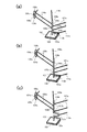
なお、本実施形態では、2本の第1リンクバー106aの配置間隔を2本の第2リンクバー107aの配置間隔よりも狭くしている。そして、出力軸103に対する2本の第1リンクバー106aの接続位置を、同じく2本の第2リンクバー107aの2つの接続位置に挟まれた位置に配置している。このことで、出力軸103に対して水平方向に掛かる力のバランスが良好となるので、出力軸103の傾きを防止でき好適である。なお、2本の第1リンクバー106aの配置間隔を2本の第2リンクバー107aの配置間隔よりも広くして、出力軸103に対する2本の第2リンクバー107aの接続位置を、2本の第1リンクバー106aの2つの接続位置に挟まれた位置に配置してもよく、同様に好適である。   In the present embodiment, the arrangement interval between the two first link bars 106a is narrower than the arrangement interval between the two second link bars 107a. And the connection position of the two 1st link bars 106a with respect to the output shaft 103 is arrange | positioned in the position pinched | interposed into the two connection positions of the two 2nd link bars 107a. As a result, the balance of the forces applied in the horizontal direction with respect to the output shaft 103 becomes good, which is preferable because it prevents the output shaft 103 from being inclined. In addition, the arrangement interval of the two first link bars 106a is made wider than the arrangement interval of the two second link bars 107a, and the connection position of the two second link bars 107a with respect to the output shaft 103 is set to two. The first link bar 106a may be disposed at a position sandwiched between two connection positions, and is similarly suitable.

しかし、2本の第1リンクバー106aの幅を2本の第2リンクバー107aの幅と等しくし、出力軸103に対する接続位置を例えば図4(a)、図4(b)のように変更しても良い。図4(a)では、第1リンクバー106aと第2リンクバー107aを出力軸103に対して交互に接続している。また、図4(b)では、2本の第1リンクバー106aに対して2本の第2リンクバー107aを軸方向にずらして接続している。また、図4(c)では、出力軸103に出力側腕部に相当するクランク部103bを設け、クランク部103bに第4リンクバー112aを接続した変形例である。即ち、出力軸アーム103aに代えて、出力軸103の一部を水平方向に突出するように折り曲げ形成したクランク部103bを設けている。このようにクランク部103bとすることで、出力軸103の回転角度の範囲を広げることが可能となる。   However, the width of the two first link bars 106a is made equal to the width of the two second link bars 107a, and the connection position with respect to the output shaft 103 is changed, for example, as shown in FIGS. 4 (a) and 4 (b). You may do it. In FIG. 4A, the first link bar 106 a and the second link bar 107 a are alternately connected to the output shaft 103. In FIG. 4B, the two second link bars 107a are connected to the two first link bars 106a while being shifted in the axial direction. FIG. 4C shows a modification in which the output shaft 103 is provided with a crank portion 103b corresponding to the output side arm portion, and the fourth link bar 112a is connected to the crank portion 103b. That is, instead of the output shaft arm 103a, a crank portion 103b formed by bending a part of the output shaft 103 so as to protrude in the horizontal direction is provided. By using the crank portion 103b as described above, the range of the rotation angle of the output shaft 103 can be expanded.

また、第4モータ110を、他のモータの位置に無関係な位置に配置し、2本のリンクバーによる平行リンク機構を2組用いるか又は、平行リンク機構とベルト式の回転伝達機構の組合せによる回転伝達機構を用いる構成とすることも可能である。この場合は回転伝達機構と第2軸105b等との連結は行わない。また、この場合は第2モータ105と第2軸105bをリニアアクチュエータとその移動子に変更することも可能である。   Further, the fourth motor 110 is arranged at a position unrelated to the positions of other motors, and two sets of parallel link mechanisms using two link bars are used, or a combination of a parallel link mechanism and a belt type rotation transmission mechanism. A configuration using a rotation transmission mechanism is also possible. In this case, the rotation transmission mechanism and the second shaft 105b are not connected. In this case, the second motor 105 and the second shaft 105b can be changed to a linear actuator and its mover.

本実施形態によれば、出力部材102の、出力軸に交差する方向の移動を第1モータ104及び第2モータ105により、概ね鉛直方向の移動を第3モータ108により、回動を第4モータ110により、それぞれ制御するため、制御を簡単に行える。即ち、位置決めの目標位置に対して第1、第2、第3の各モータの駆動量(制御量)は互いに関係があるものの、それぞれ制御する方向(移動方向)が出力軸に交差する概ね水平方向か、概ね鉛直方向かに決まっているため、それぞれの駆動量の算出を簡単に行える。また、第4モータに関しては第1、第2、第3の各モータの駆動量に無関係に駆動量を簡単に決定できる。   According to this embodiment, the movement of the output member 102 in the direction intersecting the output shaft is moved by the first motor 104 and the second motor 105, the movement in the substantially vertical direction is moved by the third motor 108, and the rotation is rotated by the fourth motor. Since each control is performed by 110, the control can be easily performed. That is, although the driving amounts (control amounts) of the first, second, and third motors are related to the target position for positioning, the respective control directions (moving directions) intersect the output shaft substantially horizontally. Since the direction is determined to be approximately vertical, each drive amount can be easily calculated. Further, regarding the fourth motor, the driving amount can be easily determined regardless of the driving amounts of the first, second, and third motors.

また、本実施形態の場合、出力軸103の軸線上に各リンクバーから接続されるジョイント部を配列したので、リンクバーからの力が作用する作用点は出力軸103の軸線方向から見たときに一致する。このため、出力軸103の位置決めに対して作用点のずれによる偏差を生じることがない。従って、位置決め誤差の少ないパラレルリンクロボットが提供できるとともに、位置決め位置に対して各アクチュエータの駆動量の算出が容易となる。   In the case of this embodiment, since the joint portions connected from each link bar are arranged on the axis of the output shaft 103, the point of action where the force from the link bar acts is viewed from the axial direction of the output shaft 103. Matches. For this reason, there is no deviation due to the deviation of the operating point with respect to the positioning of the output shaft 103. Accordingly, it is possible to provide a parallel link robot with little positioning error and to easily calculate the driving amount of each actuator with respect to the positioning position.

また、第1、第2、第3、第4モータ104、105、108、110を、水平方向に関し出力部材102の移動領域に対して外れた位置に配置しているため、クリーンな環境で出力部材102による加工や組み立て作業等を行うことができる。即ち、出力部材102が何れかのモータの下側に位置すると、このモータの駆動により例えばモータに付着したごみなどの異物が出力部材102に設けた工具により加工などがされるワークに落下して、ワークを汚染する可能性がある。特に、クリーンな環境でワークの加工などを行う場合、極僅かな異物が品質に影響を与えてしまう。そこで、本実施形態では、各モータ104、105、108、110を、水平方向に関し出力部材102の移動領域に対して外れた位置に配置して、出力部材102がどこに移動しても何れかのモータの鉛直方向下側に位置することを防止している。そして、ワークに異物が付着することを低減している。   In addition, since the first, second, third, and fourth motors 104, 105, 108, and 110 are arranged at positions that deviate from the moving region of the output member 102 in the horizontal direction, output is performed in a clean environment. Processing or assembly work by the member 102 can be performed. That is, when the output member 102 is positioned below any of the motors, foreign matters such as dust attached to the motor are dropped onto a workpiece to be processed by a tool provided on the output member 102 by driving the motor. , May contaminate the workpiece. In particular, when a workpiece is processed in a clean environment, a very small amount of foreign matter affects the quality. Therefore, in the present embodiment, each motor 104, 105, 108, 110 is disposed at a position deviating from the movement region of the output member 102 with respect to the horizontal direction, and no matter where the output member 102 moves, It is prevented from being located on the lower side in the vertical direction of the motor. And it is reducing that a foreign material adheres to a workpiece | work.

また、本実施形態では、第1、第2、第3、第4モータ104、105、108、110を、それぞれの可動部が出力部材102側に突出しないように収納するケース101を有するため、異物がよりワークに付着しにくい。   Further, in the present embodiment, since the first, second, third, and fourth motors 104, 105, 108, and 110 are housed so that the respective movable parts do not protrude toward the output member 102 side, Foreign matter is less likely to adhere to the workpiece.

<第2の実施形態>
本発明の第2の実施形態について、図5を用いて説明する。本実施形態は、上述の第1の実施形態に対し、第1軸104bを第1アーム104aに支持する軸受104c、第2軸105bを第2アーム105aに支持する軸受105cを省略している。そして、第1軸104bと第1アーム104aとを固定または一体化し、第2軸105bと第2アーム105aとを固定または一体化している。
<Second Embodiment>
A second embodiment of the present invention will be described with reference to FIG. In the present embodiment, the bearing 104c that supports the first shaft 104b on the first arm 104a and the bearing 105c that supports the second shaft 105b on the second arm 105a are omitted from the first embodiment described above. The first shaft 104b and the first arm 104a are fixed or integrated, and the second shaft 105b and the second arm 105a are fixed or integrated.

また、これに伴い、第1リンクバー106aと第1軸104bとを連結する第1駆動側ジョイント部106c´と、第2リンクバー107aと第2軸105bとを連結する第2駆動側ジョイント部107c´とを、それぞれ2自由度を有するものとしている。即ち、第1の実施形態に比べて、リンクバーをz軸に略平行な軸回りに回動自在としている。   Accordingly, the first drive side joint portion 106c ′ for connecting the first link bar 106a and the first shaft 104b, and the second drive side joint portion for connecting the second link bar 107a and the second shaft 105b. 107c ′ is assumed to have two degrees of freedom. That is, as compared with the first embodiment, the link bar is rotatable around an axis substantially parallel to the z axis.

具体的には、第1駆動側ジョイント部106c´は、第1リンクバー106aに、第1軸104b回りの回動、及び、第1軸104b及び第1リンクバー106aの配設方向に直交する直交軸を中心とした回動を可能とする自由度を有している。また、第2駆動側ジョイント部107c´は、第2リンクバー107aに、第2軸105b回り、及び、第2軸105b及び第2リンクバー107aの配設方向に直交する直交軸を中心とした回動を可能とする自由度を有している。このようなジョイント部106c´、107c´としては、例えば、前述の図3に示した構造のものを使用できる。   Specifically, the first drive side joint portion 106c ′ is orthogonal to the first link bar 106a, the rotation around the first shaft 104b, and the arrangement direction of the first shaft 104b and the first link bar 106a. It has a degree of freedom that enables rotation about an orthogonal axis. Further, the second drive side joint portion 107c ′ is centered on the second link bar 107a around the second shaft 105b and an orthogonal axis orthogonal to the arrangement direction of the second shaft 105b and the second link bar 107a. It has a degree of freedom that enables rotation. As such joint parts 106c 'and 107c', the thing of the structure shown in above-mentioned FIG. 3 can be used, for example.

本実施形態の場合、第1駆動側ジョイント部106c´及び第2駆動側ジョイント部107c´として、2自由度のジョイント部を使用できるので、他の2自由度のジョイント部と部品の共通化が可能となる。例えば、ジョイント部106b、106c´、107b、107c´、109b、111b、111c、112b、112cに同一部品を使用できる。このため、製造コストを低減できる。その他の構造及び作用は、上述の第1の実施形態と同様である。   In the case of this embodiment, since the joint part with two degrees of freedom can be used as the first drive side joint part 106c ′ and the second drive side joint part 107c ′, the joint part with the other two degree of freedom joint part can be shared. It becomes possible. For example, the same parts can be used for the joint portions 106b, 106c ′, 107b, 107c ′, 109b, 111b, 111c, 112b, and 112c. For this reason, manufacturing cost can be reduced. Other structures and operations are the same as those in the first embodiment.

<第3の実施形態>
本発明の第3の実施形態について、図6を用いて説明する。本実施形態は、上述の第1、第2の実施形態と異なり、出力部材102及び出力軸103に対して回転自在な回転軸120を設けている。このために、出力部材102の下方に軸受121を介して回転軸120を設けている。また、回転軸120には、水平方向に突出するように回転軸アーム120aを設けている。そして、回転軸アーム120aの先端部と第4リンクバー112aの一端部とを、2自由度の第4出力側ジョイント部112bにより連結している。本実施形態では、回転軸アーム120aが上述の各実施形態の出力軸アーム103aに相当する。
<Third Embodiment>
A third embodiment of the present invention will be described with reference to FIG. Unlike the first and second embodiments described above, this embodiment is provided with a rotating shaft 120 that is rotatable with respect to the output member 102 and the output shaft 103. For this purpose, a rotating shaft 120 is provided below the output member 102 via a bearing 121. Further, the rotary shaft 120 is provided with a rotary shaft arm 120a so as to protrude in the horizontal direction. And the front-end | tip part of the rotating shaft arm 120a and the one end part of the 4th link bar 112a are connected by the 4th output side joint part 112b of 2 degrees of freedom. In the present embodiment, the rotary shaft arm 120a corresponds to the output shaft arm 103a of each of the above-described embodiments.

このような本実施形態の場合、ワークの移動や加工などを行う工具は回転軸120に設けられる。これにより、出力軸103を回転させることなく、回転軸120を回転させられる。その他の構造及び作用は、上述の第2の実施形態と同様である。   In the case of this embodiment, a tool for moving or machining a workpiece is provided on the rotary shaft 120. Thereby, the rotating shaft 120 can be rotated without rotating the output shaft 103. Other structures and operations are the same as those in the second embodiment.

<第4の実施形態>
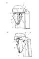
本発明の第4の実施形態について、図7及び図8を用いて説明する。本実施形態は、上述の各実施形態と異なり、第4出力側ジョイント部112bを、鉛直方向に関し、2個の第1出力側ジョイント部106bと、2個の第2出力側ジョイント部107bとの間に配置している。特に、本実施形態では、2個の第1出力側ジョイント部106bを結ぶ線分の中点と、2個の第2出力側ジョイント部107bを結ぶ線分の中点とを略一致させている。そして、第4出力側ジョイント部112bは、この略一致した中点と鉛直方向に関して略同等の位置に配置している。
<Fourth Embodiment>
A fourth embodiment of the present invention will be described with reference to FIGS. In the present embodiment, unlike the above-described embodiments, the fourth output side joint portion 112b is formed by connecting two first output side joint portions 106b and two second output side joint portions 107b in the vertical direction. Arranged in between. In particular, in the present embodiment, the midpoint of the line connecting the two first output side joint portions 106b and the midpoint of the line connecting the two second output side joint portions 107b are substantially matched. . And the 4th output side joint part 112b is arrange | positioned in the substantially equivalent position regarding this substantially matched midpoint and the vertical direction.

本実施形態の場合、第4出力側ジョイント部112bが連結されるのは、前述の図4(c)に示したようなクランク部103bとしている。但し、図9に示すように、出力軸アーム103aに第4出力側ジョイント部112bを連結する構造であっても良い。何れの構造の場合でも、第4モータ110の駆動により出力軸103を回動させる力の作用点を、第1、第2モータ104、105により出力軸103を移動させる力の仮想的な作用点と鉛直方向に関し略同等にできる。このため、出力軸103の移動及び回動を安定して行うことができ、位置決め誤差や回動誤差などを低減できる。   In the present embodiment, the fourth output side joint portion 112b is connected to the crank portion 103b as shown in FIG. However, as shown in FIG. 9, a structure in which the fourth output side joint portion 112b is connected to the output shaft arm 103a may be employed. In any structure, the action point of the force that rotates the output shaft 103 by driving the fourth motor 110 is the virtual action point of the force that moves the output shaft 103 by the first and second motors 104 and 105. And substantially the same in the vertical direction. For this reason, the output shaft 103 can be moved and rotated stably, and positioning errors and rotation errors can be reduced.

また、本実施形態では、第2モータ105により水平方向に移動させられる第2軸105bの下端部に、軸受105dを介して回転部材であるリンクアーム105e、105fを回転自在に支持している。これらリンクアーム105e、105fは、軸受105dに対して上方から見て異なる角度でそれぞれ水平方向に設けられている。そして、リンクアーム105eにリンクバー111aを、リンクアーム105fに第4リンクバー112aを、それぞれ連結している。リンクアーム105fの水平方向の長さは、クランク部103bの水平方向の突出量(出力軸アーム103aの水平方向の長さに相当)と同じとし、第4モータ110の駆動によりリンクアーム105e、105fを介して、出力軸103を回動させる。本実施形態によれば、出力軸103の回転可能な範囲をより広くすることができる。なお、本実施形態では、出力部材の図示を省略している。その他の構造及び作用は、前述の第1の実施形態と同様である。   In this embodiment, link arms 105e and 105f, which are rotating members, are rotatably supported via bearings 105d at the lower end of the second shaft 105b that is moved in the horizontal direction by the second motor 105. These link arms 105e and 105f are respectively provided in the horizontal direction at different angles when viewed from above with respect to the bearing 105d. The link bar 111a is connected to the link arm 105e, and the fourth link bar 112a is connected to the link arm 105f. The horizontal length of the link arm 105f is the same as the horizontal projection amount of the crank portion 103b (corresponding to the horizontal length of the output shaft arm 103a), and the link arm 105e, 105f is driven by the fourth motor 110. , The output shaft 103 is rotated. According to this embodiment, the rotatable range of the output shaft 103 can be made wider. In the present embodiment, the output member is not shown. Other structures and operations are the same as those in the first embodiment.

<第5の実施形態>
本発明の第5の実施形態について、図10及び図11を用いて説明する。本実施形態では、上述の各実施形態と異なり、2個の第1出力側ジョイント部106bと、2個の第2出力側ジョイント部107bとを同一軸上に配置していない。即ち、これらジョイント部106b、107bを出力軸103に沿って配列させていない。このために、出力部材102の出力軸103から外れた位置に、2本のアーム102a、102bを固定している。これらアーム102a、102bは、z軸と平行に配置されている。そして、第1リンクバー106aをアーム102aに第1出力側ジョイント部106bにより連結し、第2リンクバー107aをアーム102bに第2出力側ジョイント部107bにより連結している。
<Fifth Embodiment>
A fifth embodiment of the present invention will be described with reference to FIGS. In the present embodiment, unlike the above-described embodiments, the two first output side joint portions 106b and the two second output side joint portions 107b are not arranged on the same axis. That is, these joint portions 106 b and 107 b are not arranged along the output shaft 103. For this purpose, the two arms 102 a and 102 b are fixed at a position off the output shaft 103 of the output member 102. These arms 102a and 102b are arranged in parallel with the z-axis. The first link bar 106a is connected to the arm 102a by the first output side joint portion 106b, and the second link bar 107a is connected to the arm 102b by the second output side joint portion 107b.

また、本実施形態の場合も、前述の図6に示した構造と同様に、出力部材102及び出力軸103に対して回転自在な回転軸120を設けている。このために、出力部材102の下方に軸受121を介して回転軸120を設け、回転軸120の一部を水平方向に突出するように折り曲げてクランク部120bを形成している。そして、このクランク部120bに第4リンクバー112aの一端部を、2自由度の第4出力側ジョイント部112bにより連結している。   In the case of the present embodiment as well, a rotating shaft 120 that is rotatable with respect to the output member 102 and the output shaft 103 is provided as in the structure shown in FIG. For this purpose, a rotating shaft 120 is provided below the output member 102 via a bearing 121, and a part of the rotating shaft 120 is bent so as to protrude in the horizontal direction to form a crank portion 120b. Then, one end portion of the fourth link bar 112a is connected to the crank portion 120b by a four-degree-of-freedom fourth output side joint portion 112b.

本実施形態の場合、リンクバー106a、107aと出力部材102との連結部を、上述のように出力軸103からずらすことにより、平行リンク機構をより自由に構成することが可能となる。その他の構造及び作用は、前述の第1、第3の実施形態と同様である。   In the case of the present embodiment, the parallel link mechanism can be configured more freely by shifting the connecting portion between the link bars 106a and 107a and the output member 102 from the output shaft 103 as described above. Other structures and operations are the same as those in the first and third embodiments described above.

<他の実施形態>
上述の各実施形態では、ケース101はベース部材を兼ねるものとしたが、例えばケース101をカバー部材として、パラレルリンクロボットに対して着脱可能とし、各モータを覆う構造にしても良い。また、パラレルリンクロボットの機構部から部分的に露出するアクチュエータを覆うためのカバー部材を用いても良い。このように、本発明のケース101としては上記のカバー部材及び、カバー部材と他の機構部材の任意の組合せも含むものとする。また、各実施形態の構成は、適宜組み合わせて実施することができる。
<Other embodiments>
In each of the embodiments described above, the case 101 also serves as a base member. However, for example, the case 101 may be used as a cover member so that the case 101 can be attached to and detached from the parallel link robot and covers each motor. Further, a cover member for covering the actuator partially exposed from the mechanism part of the parallel link robot may be used. As described above, the case 101 of the present invention includes the above-described cover member and any combination of the cover member and another mechanism member. In addition, the configurations of the respective embodiments can be implemented in combination as appropriate.

100 パラレルリンクロボット
101 ケース
102 出力部材
103 出力軸
103a 出力軸アーム(出力側腕部)
103b クランク部(出力側腕部)
104 第1モータ(第1アクチュエータ)
104b 第1軸
105 第2モータ(第2アクチュエータ)
105b 第2軸
105e、105f リンクアーム(回転部材、駆動側腕部)
106 第1リンク機構
106a 第1リンクバー(第1リンク部材)
106b 第1出力側ジョイント部
106c、106c´ 第1駆動側ジョイント部
107 第2リンク機構
107a 第2リンクバー(第2リンク部材)
107b 第2出力側ジョイント部
107c、107c´ 第2駆動側ジョイント部
108 第3モータ(第3アクチュエータ)
109 第3リンク機構
109a 第3リンクバー(第3リンク部材)
109b 第3出力側ジョイント部
109c 第3駆動側ジョイント部
110 第4モータ(第4アクチュエータ)
111 回転伝達手段
112 第4リンク機構
112a 第4リンクバー(第4リンク部材)
112b 第4出力側ジョイント部
112c 第4駆動側ジョイント部
120 回転軸
120a 回転軸アーム(出力側腕部)
120b クランク部(出力側腕部)
DESCRIPTION OF SYMBOLS 100 Parallel link robot 101 Case 102 Output member 103 Output shaft 103a Output shaft arm (output side arm part)
103b Crank part (output side arm part)
104 First motor (first actuator)
104b First shaft 105 Second motor (second actuator)
105b Second shaft 105e, 105f Link arm (rotating member, drive side arm)
106 First link mechanism 106a First link bar (first link member)
106b 1st output side joint part 106c, 106c '1st drive side joint part 107 2nd link mechanism 107a 2nd link bar (2nd link member)
107b 2nd output side joint part 107c, 107c '2nd drive side joint part 108 3rd motor (3rd actuator)
109 Third link mechanism 109a Third link bar (third link member)
109b 3rd output side joint part 109c 3rd drive side joint part 110 4th motor (4th actuator)
111 Rotation transmission means 112 Fourth link mechanism 112a Fourth link bar (fourth link member)
112b 4th output side joint part 112c 4th drive side joint part 120 rotating shaft 120a rotating shaft arm (output side arm part)
120b Crank part (output side arm part)

Claims (7)

鉛直方向と略平行な回転軸を有する出力部材と、
前記出力部材を前記回転軸と交差する方向に移動させる第1アクチュエータ及び第2アクチュエータと、
前記出力部材を概ね鉛直方向に移動させる第3アクチュエータと、
前記出力部材を前記回転軸回りに回動させる第4アクチュエータと、
前記出力部材と、前記第1、第2、第3、第4アクチュエータとの間にそれぞれ設けられた複数のリンク機構と、を備え、
前記第1、第2、第3アクチュエータ及び前記複数のリンク機構により、前記出力部材を鉛直方向に対して傾斜させることなく、鉛直方向及び水平方向に移動可能であり、且つ、前記第4アクチュエータにより前記出力部材を前記回転軸回りに回転可能で、
前記第1、第2、第3、第4アクチュエータを、水平方向に関し前記出力部材の移動領域に対して外れた位置に配置した、
ことを特徴とするパラレルリンクロボット。
An output member having a rotation axis substantially parallel to the vertical direction;
A first actuator and a second actuator for moving the output member in a direction intersecting the rotation axis;
A third actuator for moving the output member in a substantially vertical direction;
A fourth actuator for rotating the output member about the rotation axis;
A plurality of link mechanisms respectively provided between the output member and the first, second, third, and fourth actuators;
The output member can be moved in the vertical direction and the horizontal direction without being inclined with respect to the vertical direction by the first, second, and third actuators and the plurality of link mechanisms, and by the fourth actuator. The output member is rotatable about the rotation axis;
The first, second, third, and fourth actuators are disposed at positions deviating from the moving region of the output member in the horizontal direction.
A parallel link robot characterized by that.
前記第1アクチュエータと前記第2アクチュエータとは、装置の上方から眺めた場合に前記第1アクチュエータの中心と前記出力部材の中心とを結ぶ線分と、前記第2アクチュエータの中心と前記出力部材の中心とを結ぶ線分との成す角度が、0°よりも大きく且つ180°よりも小さくなるように配置され、
前記第3アクチュエータ及び前記第4アクチュエータは、水平方向に関し、前記第1アクチュエータと前記第2アクチュエータとの間に配置されている、
ことを特徴とする、請求項1に記載のパラレルリンクロボット。
The first actuator and the second actuator are a line segment connecting the center of the first actuator and the center of the output member when viewed from above the device, the center of the second actuator, and the output member. The angle formed by the line connecting the center is arranged so that it is larger than 0 ° and smaller than 180 °,
The third actuator and the fourth actuator are disposed between the first actuator and the second actuator in the horizontal direction.
The parallel link robot according to claim 1, wherein:
前記第1、第2、第3、第4アクチュエータを、それぞれの可動部が前記出力部材側に突出しないように収納するケースを有する、
ことを特徴とする、請求項1又は2に記載のパラレルリンクロボット。
A housing for storing the first, second, third, and fourth actuators so that each movable portion does not protrude toward the output member;
The parallel link robot according to claim 1, wherein the robot is a parallel link robot.
前記出力部材と前記第1アクチュエータ及び前記第2アクチュエータとの間にそれぞれ設けられた第1リンク機構及び第2リンク機構は、前記出力部材の回転軸と平行で前記出力部材から水平方向に外れた位置に配置され、前記第1アクチュエータ又は前記第2アクチュエータの駆動により移動させられる第1軸及び第2軸と、前記第1軸又は前記第2軸と前記出力部材との間に、それぞれ互いに平行に配置された複数の第1リンク部材及び複数の第2リンク部材と、をそれぞれ有し、
前記第1軸、前記出力部材、前記複数の第1リンク部材で平行リンク機構を構成し、前記第2軸、前記出力部材、前記複数の第2リンク部材で平行リンク機構を構成している、
ことを特徴とする、請求項1ないし3のうちの何れか1項に記載のパラレルリンクロボット。
The first link mechanism and the second link mechanism provided between the output member and the first actuator and the second actuator, respectively, are parallel to the rotation axis of the output member and are horizontally displaced from the output member. The first shaft and the second shaft that are arranged at positions and are moved by driving the first actuator or the second actuator, and the first shaft or the second shaft and the output member are parallel to each other. Each having a plurality of first link members and a plurality of second link members,
The first shaft, the output member, and the plurality of first link members constitute a parallel link mechanism, and the second shaft, the output member, and the plurality of second link members constitute a parallel link mechanism.
The parallel link robot according to claim 1, wherein the parallel link robot is characterized in that:
前記第1軸又は前記第2軸に回転自在に支持された回転部材と、
前記第4アクチュエータの駆動を前記回転部材に伝達する回転伝達手段と、を有し、
前記出力部材と前記第4アクチュエータとの間に設けられた第4リンク機構は、前記出力部材と前記回転部材との間に配置される、
ことを特徴とする、請求項4に記載のパラレルリンクロボット。
A rotating member rotatably supported by the first shaft or the second shaft;
Rotation transmission means for transmitting the drive of the fourth actuator to the rotation member;
A fourth link mechanism provided between the output member and the fourth actuator is disposed between the output member and the rotating member;
The parallel link robot according to claim 4, wherein:
前記第3アクチュエータは、回転型アクチュエータ又はリニアアクチュエータであり、前記出力部材よりも鉛直方向に関して上方で且つ前記出力部材から水平方向に関して外れた位置に配置され、
前記出力部材と前記第3アクチュエータとの間に設けられた第3リンク機構は、前記第3アクチュエータにより動かされる可動部材と、前記可動部材と前記出力部材との間に配置された第3リンク部材と、を有し、
前記第3リンク部材を介して、前記可動部材の運動により、前記出力部材を概ね鉛直方向に移動させる、
ことを特徴とする、請求項1ないし5のうちの何れか1項に記載のパラレルリンクロボット。
The third actuator is a rotary actuator or a linear actuator, and is disposed at a position above the output member in the vertical direction and away from the output member in the horizontal direction,
The third link mechanism provided between the output member and the third actuator includes a movable member that is moved by the third actuator, and a third link member that is disposed between the movable member and the output member. And having
The output member is moved substantially vertically by the movement of the movable member via the third link member.
The parallel link robot according to any one of claims 1 to 5, wherein the parallel link robot is characterized in that:
前記第1アクチュエータと前記第2アクチュエータとのうちの少なくとも一方は、回転型アクチュエータであり、
前記第4アクチュエータは、回転型アクチュエータであり、
前記第4アクチュエータを、その回転軸が、回転型アクチュエータである前記第1アクチュエータ又は前記第2アクチュエータの回転軸と同軸上となるように配置した、
ことを特徴とする、請求項1ないし6のうちの何れか1項に記載のパラレルリンクロボット。
At least one of the first actuator and the second actuator is a rotary actuator,
The fourth actuator is a rotary actuator,
The fourth actuator is arranged so that its rotation axis is coaxial with the rotation axis of the first actuator or the second actuator, which is a rotary actuator.
The parallel link robot according to any one of claims 1 to 6, wherein the robot is a parallel link robot.
JP2011058994A 2011-03-17 2011-03-17 Parallel link robot Pending JP2012192499A (en)

Priority Applications (1)

Application Number Priority Date Filing Date Title
JP2011058994A JP2012192499A (en) 2011-03-17 2011-03-17 Parallel link robot

Applications Claiming Priority (1)

Application Number Priority Date Filing Date Title
JP2011058994A JP2012192499A (en) 2011-03-17 2011-03-17 Parallel link robot

Publications (2)

Publication Number Publication Date
JP2012192499A true JP2012192499A (en) 2012-10-11
JP2012192499A5 JP2012192499A5 (en) 2014-05-01

Family

ID=47084905

Family Applications (1)

Application Number Title Priority Date Filing Date
JP2011058994A Pending JP2012192499A (en) 2011-03-17 2011-03-17 Parallel link robot

Country Status (1)

Country Link
JP (1) JP2012192499A (en)

Cited By (4)

* Cited by examiner, † Cited by third party
Publication number Priority date Publication date Assignee Title
CN103286773A (en) * 2013-07-01 2013-09-11 安徽工业大学 Three-DOF (Degree of Freedom) parallel robot mechanism
KR101859297B1 (en) * 2016-12-07 2018-06-27 고려대학교 세종산학협력단 Four degree of freedom mechanism apparatus
JPWO2022176967A1 (en) * 2021-02-17 2022-08-25
WO2023085338A1 (en) * 2021-11-09 2023-05-19 望月玲於奈 Rotary mechanism, aerial vehicle, load attitude control device, and method

Citations (12)

* Cited by examiner, † Cited by third party
Publication number Priority date Publication date Assignee Title
JPH01306192A (en) * 1988-05-31 1989-12-11 Pentel Kk Driving device for arm of robot
JPH06143165A (en) * 1992-10-30 1994-05-24 Japan Airlines Co Ltd Robot for work
WO1998030366A1 (en) * 1997-01-14 1998-07-16 Asea Brown Boveri Ab A device for relative displacement of two elements
WO1999058301A1 (en) * 1998-04-29 1999-11-18 Abb Ab A device for relative movement of two elements
US6095011A (en) * 1996-03-14 2000-08-01 Abb Ab Device for relative movement of two elements
US20010002098A1 (en) * 1997-11-03 2001-05-31 Douglas Haanpaa Haptic pointing devices
WO2003078111A1 (en) * 2002-03-18 2003-09-25 Abb Ab Manipulator and method involving a manipulator for movement of an object, comprising at least two driving parallel kinematic connecting chains
US20040013509A1 (en) * 1999-08-05 2004-01-22 Roy Shambhu Nath Parallel kinematics mechanism with a concentric spherical joint
JP2004508950A (en) * 2000-09-11 2004-03-25 エービービー エービー Manipulator with three or more arms to move objects in space
JP2005516784A (en) * 2002-02-06 2005-06-09 アーベーベー・アーベー Industrial robot
US20060245894A1 (en) * 2005-03-21 2006-11-02 Michael Merz Parallel robot
WO2012031954A1 (en) * 2010-09-10 2012-03-15 Abb Research Ltd An industrial robot including a parallel kinematic manipulator

Patent Citations (12)

* Cited by examiner, † Cited by third party
Publication number Priority date Publication date Assignee Title
JPH01306192A (en) * 1988-05-31 1989-12-11 Pentel Kk Driving device for arm of robot
JPH06143165A (en) * 1992-10-30 1994-05-24 Japan Airlines Co Ltd Robot for work
US6095011A (en) * 1996-03-14 2000-08-01 Abb Ab Device for relative movement of two elements
WO1998030366A1 (en) * 1997-01-14 1998-07-16 Asea Brown Boveri Ab A device for relative displacement of two elements
US20010002098A1 (en) * 1997-11-03 2001-05-31 Douglas Haanpaa Haptic pointing devices
WO1999058301A1 (en) * 1998-04-29 1999-11-18 Abb Ab A device for relative movement of two elements
US20040013509A1 (en) * 1999-08-05 2004-01-22 Roy Shambhu Nath Parallel kinematics mechanism with a concentric spherical joint
JP2004508950A (en) * 2000-09-11 2004-03-25 エービービー エービー Manipulator with three or more arms to move objects in space
JP2005516784A (en) * 2002-02-06 2005-06-09 アーベーベー・アーベー Industrial robot
WO2003078111A1 (en) * 2002-03-18 2003-09-25 Abb Ab Manipulator and method involving a manipulator for movement of an object, comprising at least two driving parallel kinematic connecting chains
US20060245894A1 (en) * 2005-03-21 2006-11-02 Michael Merz Parallel robot
WO2012031954A1 (en) * 2010-09-10 2012-03-15 Abb Research Ltd An industrial robot including a parallel kinematic manipulator

Cited By (6)

* Cited by examiner, † Cited by third party
Publication number Priority date Publication date Assignee Title
CN103286773A (en) * 2013-07-01 2013-09-11 安徽工业大学 Three-DOF (Degree of Freedom) parallel robot mechanism
KR101859297B1 (en) * 2016-12-07 2018-06-27 고려대학교 세종산학협력단 Four degree of freedom mechanism apparatus
JPWO2022176967A1 (en) * 2021-02-17 2022-08-25
WO2022176967A1 (en) * 2021-02-17 2022-08-25 望月玲於奈 Rotary mechanism, flight vehicle, and device and method for controlling attitude of load
JP7383213B2 (en) 2021-02-17 2023-11-20 玲於奈 望月 Rotation mechanism, flying vehicle, payload attitude control device and method
WO2023085338A1 (en) * 2021-11-09 2023-05-19 望月玲於奈 Rotary mechanism, aerial vehicle, load attitude control device, and method

Similar Documents

Publication Publication Date Title
US8893578B2 (en) Parallel robot provided with wrist section having three degrees of freedom
US20100206120A1 (en) Parallel robot provided with wrist section having three degrees of freedom
US20130142608A1 (en) Parallel mechanism
JP4125960B2 (en) Industrial robot
JP6914568B2 (en) Industrial robot arm
JP2010115776A (en) Articulated structure of multiple-axis robot and robot comprising such structure
JP2006341283A (en) Positioner for arc welding, and arc welding robot system
JP6582491B2 (en) robot
WO2018105584A1 (en) Industrial robot
JP2014124742A (en) Arm-driving device
JP6110620B2 (en) Parallel link robot
JP2004291166A (en) Four degree-of-freedom parallel robot
JP2012192499A (en) Parallel link robot
JP2014039977A (en) Parallel robot
CN111819038B (en) Working equipment adopting parallel link mechanism and control method thereof
JP6677970B2 (en) Industrial robot
JP2012192500A (en) Parallel link robot
JP5833869B2 (en) Delta parallel robot
KR101649108B1 (en) A joint structure and a robot having the same
JP4270041B2 (en) Robot wrist device and robot equipped with the same
JP2018069354A (en) Link type multi-joint robot
JP6043561B2 (en) Parallel link robot
JP5866154B2 (en) Parallel link robot
JPH08243972A (en) Industrial robot having multidegree of freedom joint
JP5840590B2 (en) Movable body support device

Legal Events

Date Code Title Description
A521 Written amendment

Free format text: JAPANESE INTERMEDIATE CODE: A523

Effective date: 20140317

A621 Written request for application examination

Free format text: JAPANESE INTERMEDIATE CODE: A621

Effective date: 20140317

A977 Report on retrieval

Free format text: JAPANESE INTERMEDIATE CODE: A971007

Effective date: 20150113

A131 Notification of reasons for refusal

Free format text: JAPANESE INTERMEDIATE CODE: A131

Effective date: 20150127

A02 Decision of refusal

Free format text: JAPANESE INTERMEDIATE CODE: A02

Effective date: 20150623