JP2012191805A - Inverter device and electric tool - Google Patents
Inverter device and electric tool Download PDFInfo
- Publication number
- JP2012191805A JP2012191805A JP2011055054A JP2011055054A JP2012191805A JP 2012191805 A JP2012191805 A JP 2012191805A JP 2011055054 A JP2011055054 A JP 2011055054A JP 2011055054 A JP2011055054 A JP 2011055054A JP 2012191805 A JP2012191805 A JP 2012191805A
- Authority
- JP
- Japan
- Prior art keywords
- motor
- conduction angle
- power
- inverter device
- voltage
- Prior art date
- Legal status (The legal status is an assumption and is not a legal conclusion. Google has not performed a legal analysis and makes no representation as to the accuracy of the status listed.)
- Pending
Links
Images

Landscapes
- Portable Power Tools In General (AREA)
- Charge And Discharge Circuits For Batteries Or The Like (AREA)
- Control Of Ac Motors In General (AREA)
- Inverter Devices (AREA)
Abstract
Description
本発明は、インバータ装置及び電動工具に関する。 The present invention relates to an inverter device and a power tool.
従来より、インバータ回路を備えた電子機器が知られている。このような電子機器は、商用電源からの交流電力をトランスで変圧し、整流・平滑回路で直流電力に整流・平滑した後、インバータ回路で所定の交流電力に変換してACモータ等に出力している(例えば、特許文献1参照)。 Conventionally, an electronic device including an inverter circuit is known. Such an electronic device transforms AC power from a commercial power source with a transformer, rectifies and smoothes it into DC power with a rectifying / smoothing circuit, converts it to predetermined AC power with an inverter circuit, and outputs it to an AC motor or the like. (For example, refer to Patent Document 1).
しかしながら、例えば、上記電子機器が芝刈り機である場合、芝刈部に草がつまることによりACモータに過負荷がかかることがあり、このような場合には、ACモータがロックした状態となり、作業が中断することとなってしまう。 However, for example, when the electronic device is a lawn mower, the AC motor may be overloaded due to grass jamming in the lawn mower. In such a case, the AC motor is locked and the work is performed. Will be interrupted.
そこで、本発明は、モータにかかる一時的な過負荷に対応可能なインバータ装置及び電動工具を提供することを目的としている。 Then, an object of this invention is to provide the inverter apparatus and electric tool which can respond to the temporary overload concerning a motor.
本発明は、設定された導通角により直流電力を交流電力に変換してモータに出力するインバータ回路と、前記モータにかかる負荷を検出する負荷検出手段と、前記負荷検出手段により検出された負荷に応じて前記導通角を変化させる制御手段と、を備えたことを特徴とするインバータ装置を提供している。 The present invention provides an inverter circuit that converts DC power into AC power according to a set conduction angle and outputs the AC power, a load detection unit that detects a load applied to the motor, and a load detected by the load detection unit. According to another aspect of the present invention, there is provided an inverter device comprising control means for changing the conduction angle in response.
このような構成によれば、モータに過負荷がかかったような場合には、一時的に増加された電力がモータに供給されることとなるので、モータがロックして作業が中断することが防止される。 According to such a configuration, when an overload is applied to the motor, the temporarily increased power is supplied to the motor. Is prevented.
また、前記制御手段は、前記負荷が所定値以上となった場合に前記導通角を増加させることが好ましい。 Moreover, it is preferable that the said control means increases the said conduction angle, when the said load becomes more than predetermined value.
また、前記制御手段は、前記負荷が第1の所定時間に亘って前記所定値以上であった場合に前記導通角を増加させることが好ましい。 Moreover, it is preferable that the said control means increases the said conduction angle, when the said load is more than the said predetermined value over 1st predetermined time.
このような構成によれば、モータがロック状態又はロック状態に近い状態にあることを正確に把握することができるので、ロック状態又はロック状態に近い状態以外で導通角を増加させて電力を浪費することが防止される。 According to such a configuration, it is possible to accurately grasp that the motor is in the locked state or the state close to the locked state, and thus, the power is wasted by increasing the conduction angle in a state other than the locked state or the state close to the locked state. Is prevented.
また、前記制御手段は、前記導通角を増加させてから第2の所定時間経過後に前記導通角を減少させることが好ましい。 Moreover, it is preferable that the said control means reduces the said conduction angle after 2nd predetermined time progress, after increasing the said conduction angle.
このような構成によれば、長時間大きな電力が供給されてモータが破損することが防止される。 According to such a configuration, it is possible to prevent the motor from being damaged by supplying a large amount of power for a long time.
また、前記制御手段は、前記導通角を増加させてから前記第2の所定時間経過する前に前記負荷検出手段により検出された負荷が前記所定値未満であった場合に前記導通角を減少させることが好ましい。 Further, the control means decreases the conduction angle when the load detected by the load detection means is less than the predetermined value before the second predetermined time elapses after the conduction angle is increased. It is preferable.
このような構成によれば、モータに大きな電力が供給される期間を短くすることができ、ACモータ31が破損することがより適切に防止される。
According to such a configuration, the period during which large electric power is supplied to the motor can be shortened, and the
また、本発明の別の観点によれば、モータと、上記インバータ装置と、を備えたことを特徴とする電動工具を提供している。 Moreover, according to another viewpoint of this invention, the electric tool provided with the motor and the said inverter apparatus is provided.
本発明のインバータ装置及び電動工具によれば、モータにかかる一時的な過負荷に対応することが可能となる。 According to the inverter device and the electric tool of the present invention, it is possible to cope with a temporary overload applied to the motor.
図1〜図3を用いて、本発明の実施の形態によるインバータ装置1について説明する。
The
図1は、インバータ装置1の回路図である。インバータ装置1は、電池パック2から供給された直流電力を交流電力に変換して電動工具3のACモータ31に供給するために、電池パック2と電動工具3との間に接続されている。ACモータ31には、電動工具3のトリガスイッチ32が操作されると、インバータ装置1から交流電力が供給される。インバータ装置1は、電池パック2と電動工具3との間で着脱可能であるが、以下では、接続されているものとして説明する。また、本実施の形態では、電動工具3として、芝刈り機を想定するが、例えば、電動ドリル等の他の電動工具であってもよい。
FIG. 1 is a circuit diagram of the
インバータ装置1は、電池電圧検出部11と、電源部12と、昇圧回路13と、整流・平滑回路14と、昇圧電圧検出部15と、インバータ回路16と、電流検出抵抗(本発明の負荷検出手段)17と、PWM信号出力部18と、制御部(本発明の制御手段)19と、を備えている。
The
電池電圧検出部11は、電池電圧検出抵抗111及び112を備えている。電池電圧検出抵抗111及び112は、電池パック2のプラス側端子21とマイナス側端子22の間に直列に接続されており、電池パック2の電池電圧の、電池電圧検出抵抗111と電池電圧検出抵抗112とによる分圧電圧を制御部19に出力する。なお、図1に示す電池パック2は、3.6V/セルのリチウム電池セルが4本直列接続され、定格電圧14.4Vを出力する。
The battery voltage detection unit 11 includes battery
電源部12は、電池パック2のプラス側端子21と制御部19との間に直列に接続された電源スイッチ121及び定電圧回路122を備えている。定電圧回路122は、三端子レギュレータ122aと、発振防止用コンデンサ122b及び122cと、を備えており、ユーザにより電源スイッチ121がオンされると、電池パック2からの電圧を所定の直流電圧(例えば5V)に変換し、制御部19に駆動電力として供給する。なお、電源スイッチ121がオフされると、制御部19に駆動電力が供給されなくなるので、インバータ装置1全体がオフされることとなる。
The
昇圧回路13は、トランス131と、FET132と、を備えており、トランス131は、一次側巻線131aと、二次側巻線131bと、を備えている。
The booster circuit 13 includes a
一次側巻線131aは、電池パック2のプラス側端子21とマイナス側端子22の間に接続されており、トランス131の一次側巻線131aとマイナス側端子22の間には、更に、FET132が配置されている。FET132のゲートには、FET132をオン・オフさせるための第1のPWM信号が制御部19から入力され、FET132のオン・オフにより、電池パック2から供給された直流電力は交流電力に変換されてトランス131の一次側巻線131aに出力される。一次側巻線131aに入力された交流電力は、一次側巻線131aと二次側巻線131bとの巻数比に応じて変圧されて二次側巻線131bから出力される。
The primary side winding 131a is connected between the plus
整流・平滑回路14は、整流ダイオード141及び142と、平滑コンデンサ143と、を備えており、これらにより、トランス131により昇圧された交流電力を整流・平滑して直流電力として出力する。
The rectifying /
昇圧電圧検出部15は、互いに直列接続された抵抗151及び152から構成されており、整流・平滑回路14から出力された直流の昇圧電圧(平滑コンデンサ電圧、例えば140V)を検出し、昇圧電圧の、抵抗151と抵抗152とによる分圧電圧を制御部19に出力する。
The boosted voltage detection unit 15 includes resistors 151 and 152 connected in series with each other, detects a DC boosted voltage (smoothing capacitor voltage, for example, 140 V) output from the rectifying /
インバータ回路16は、4つのFET161−164から構成されており、直列に接続されたFET161及び162と、直列に接続されたFET163及び164とが、平滑コンデンサ143に並列に接続されている。詳細には、FET161のドレインは、整流ダイオード141及び142のカソードと接続され、FET161のソースは、FET162のドレインに接続されている。また、FET163のドレインは、整流ダイオード141及び142のカソードと接続され、FET163のソースは、FET164のドレインに接続されている。
The
更に、FET161のソース及びFET162のドレイン、FET163のソース及びFET164のドレインは、それぞれ、出力端子165、166と接続されており、出力端子165、166は、ACモータ31に接続されている。FET161−164のゲートには、FET161−164をオン・オフさせるための第2のPWM信号がPWM信号出力部18から入力され、FET161−164のオン・オフにより、整流・平滑回路14から出力された直流電力は交流電力に変換されて電動工具3(ACモータ31)に出力される。
Further, the source of the
第1の電流検出抵抗17は、FET162のソース及びFET164のソースと、電池パック2のマイナス側端子22との間に接続されており、第1の電流検出抵抗17の高電圧側の端子は制御部19と接続されている。このような構成により、第1の電流検出抵抗17は、ACモータ31に流れる電流を検出し、電圧として制御部19に出力する。
The first
制御部19は、昇圧電圧検出部15によって検出された昇圧電圧に基づき、目標実効値(例えば、141V)を有する交流電力がトランス131の二次側から出力されるような第1のPWM信号をFET132のゲートに出力する。また、制御部19は、目標実効値(例えば、100V)を有する交流電力がACモータ31に出力されるような第2のPWM信号をPWM信号出力部18を介してFET161−164のゲートに出力する。本実施の形態では、通常時には、制御部19は、FET161とFET164(以降、第1のセット)と、FET162とFET163(以降、第2のセット)とを、それぞれ1セットとして、第1のセットと第2のセットをデューティ比50%で交互にオン・オフさせるような第2のPWM信号を出力する。
Based on the boosted voltage detected by the boosted voltage detection unit 15, the
また、制御部19は、電池電圧検出部11によって検出された電池電圧に基づき、電池パック2の過放電の判断を行う。具体的には、電池電圧検出部11によって検出された電池電圧が所定の過放電電圧より小さい場合には、電池パック2に過放電が生じていると判断し、ACモータ31への出力を停止させるための第1のPWM信号及び第2のPWM信号を出力する。また、電池パック2は、その内部に保護ICやマイコンを備え、自ら過放電を検出して過放電信号を制御部19に出力する機能を有しており、制御部19は、信号端子LDから過放電信号を受信した場合にも、ACモータ31への出力を停止させるための第1のPWM信号及び第2のPWM信号を出力する。このような構成により、電池パック2の寿命が短くなることを防止することができる。
In addition, the
ところで、例えば、電動工具3が芝刈り機である場合、芝刈部に草がつまることによりACモータ31に過負荷がかかることがあり、このような場合には、ACモータ31がロックした状態となり、作業が中断することとなってしまう。
By the way, for example, when the
そこで、本実施の形態によるインバータ装置1では、制御部19が、電流検出抵抗17により検出された電流に応じて、第1のセット及び第2のセットのオン期間、すなわち、導通角を変化させる。
Therefore, in the
詳細には、電流検出抵抗17により検出された電流が所定値(本実施の形態では、5.8A)以上となった場合に導通角を増加させるための第2のPWM信号をFET161−164のゲートに出力する。
Specifically, the second PWM signal for increasing the conduction angle when the current detected by the
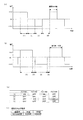
通常時には、第1のセット及び第2のセットのオン期間は、図2(a)に示すように、90度の導通角で制御されている。図2(c)に示すように、図2(a)の(1)は、第1のセットのみがオンしている期間であり、図2(a)の(3)は、第2のセットのみがオンしている期間であり、図2(a)の(2)及び(4)は、両方がオフしている期間である。 Normally, the ON period of the first set and the second set is controlled with a conduction angle of 90 degrees as shown in FIG. As shown in FIG. 2 (c), (1) in FIG. 2 (a) is a period in which only the first set is on, and (3) in FIG. 2 (a) is the second set. 2 is a period in which only both are on, and (2) and (4) in FIG. 2A are periods in which both are off.
一方、本実施の形態では、電流検出抵抗17により検出された電流が所定値以上となった場合には、導通角を150に増加させる。詳細には、図2(b)に示すように、周期は一定のままで、第1のセットのみがオンしている期間(1)及び第2のセットのみがオンしている期間(3)を増加させ、両方がオフしている期間を減少させる。
On the other hand, in the present embodiment, the conduction angle is increased to 150 when the current detected by the
図2(d)に示すように、周波数が50Hz(周期20ms)の交流電力を出力する場合を考えると、導通角が90度に設定されている場合には、第1のセット及び第2のセットのオン時間は5msであるが、導通角150度の場合には、8.3msに増加することとなる。 As shown in FIG. 2 (d), when considering the case where AC power with a frequency of 50 Hz (period 20 ms) is output, when the conduction angle is set to 90 degrees, the first set and the second The on time of the set is 5 ms, but when the conduction angle is 150 degrees, it increases to 8.3 ms.
これにより、例えば、電動工具3の芝刈部に草がつまることによりACモータ31に過負荷がかかったような場合には、一時的に増加された電力がACモータ31に供給されることとなるので、つまった草を芝刈部から取り払うことが可能となり、ACモータ31がロックして作業が中断することが防止される。
As a result, for example, when the
また、電流検出抵抗17によって検出される電流は、ノイズ等により一時的に増加する場合があるが、このような場合にまで導通角を増加させていては電力を浪費することとなる。
Further, the current detected by the
そこで、本実施の形態では、電流検出抵抗17により検出された電流が第1の所定時間(本実施の形態では、2s)に亘って上記所定値以上であった場合に導通角を増加させる。これにより、ACモータ31がロック状態又はロック状態に近い状態にあることを正確に把握することができるので、ロック状態又はロック状態に近い状態以外で導通角を増加させて電力を浪費することが防止される。
Therefore, in the present embodiment, the conduction angle is increased when the current detected by the
また、導通角を増加させてもつまった草を芝刈部から取り払うことができない場合も考えられ、このような場合にACモータ31にいつまでも大きな電力を供給していると、ACモータ31が破損する虞がある。
In addition, there may be a case where entangled grass cannot be removed from the lawn mowing unit by increasing the conduction angle. In such a case, if a large amount of power is supplied to the
そこで、本実施の形態では、導通角を増加させてから第2の所定時間(本実施の形態では、3s)経過後に、導通角を減少させる。これにより、長時間大きな電力が供給されてACモータ31が破損することが防止される。
Therefore, in the present embodiment, the conduction angle is decreased after the second predetermined time (3 s in the present embodiment) has elapsed since the conduction angle was increased. Thus, it is possible to prevent the
更に、本実施の形態では、第2の所定時間経過する前に電流検出抵抗17により検出された負荷が上記所定値未満となった場合には、その時点で導通角を減少させる。これにより、ACモータ31に大きな電力が供給される期間を短くすることができ、ACモータ31が破損することがより適切に防止される。
Furthermore, in the present embodiment, when the load detected by the
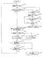
続いて、図3のフローチャートを用いて、制御部19の動作について説明する。
Next, the operation of the
図3のフローチャートは、電池パック2がインバータ装置1に装着されている状態で電源スイッチ121がオンされた時、又は、電源スイッチ121がオンされた状態で電池パック2がインバータ装置1に装着された時にスタートする。なお、電源スイッチ121をオンすることによって、電池パック2の電圧から定電圧回路122に電圧が供給されることで制御部19の駆動電圧が生成され制御部19が動作することになる。また、本フローチャートでは、制御部19は、電流検出抵抗17に検出された電流を所定サンプリング周期毎に取得するものとする(以下、検出電流)。
In the flowchart of FIG. 3, when the
まず、制御部19は、初期値として、導通角を90度に設定した上で(S301)、検出電流が所定値(本実施の形態では、5.8A)以上であるか否かを判断する(S302)。
First, after setting the conduction angle to 90 degrees as an initial value (S301), the
検出電流が所定値以上であった場合には(S302:YES)、続いて、S302で最初に“YES”と判断されてから第1の所定時間(本実施の形態では、2s)に亘って検出電流が所定値以上であったか否かを判断する(S303)。ここでは、例えば、S302で最初に“YES”と判断された時間を記憶しておき、その時間から第1の所定時間経過するまでに検出された複数の検出電流が全て上記所定値以上であったか否かを判断すればよい。 If the detected current is greater than or equal to a predetermined value (S302: YES), then, for the first predetermined time (2 s in the present embodiment) after first being determined as “YES” in S302. It is determined whether or not the detected current is greater than or equal to a predetermined value (S303). Here, for example, the time at which “YES” is first determined in S302 is stored, and whether or not all of the plurality of detected currents detected from the time until the first predetermined time elapses are equal to or greater than the predetermined value. It may be determined whether or not.
第1の所定時間に亘って検出電流が所定値以上であった場合には(S303:YES)、導通角を150度に増加させる(S304)。 If the detected current is equal to or greater than the predetermined value for the first predetermined time (S303: YES), the conduction angle is increased to 150 degrees (S304).
続いて、S304で導通角を増加させたことにより芝刈部につまった草等が取り払われたか否かを判断するために、検出電流が上記所定値以下まで低下したか否かを判断する(S305)。 Subsequently, in order to determine whether or not grass jammed in the lawn mower has been removed by increasing the conduction angle in S304, it is determined whether or not the detected current has decreased to the predetermined value or less (S305). ).
検出電流が所定値以下に低下していた場合には(S305:YES)、導通角を増加させたことにより芝刈部につまった草等が取り払われたものと考えられるため、導通角を初期値の90度に再設定する(S307)。 If the detected current has fallen below the predetermined value (S305: YES), it is considered that grass or the like stuck in the lawn mower has been removed by increasing the conduction angle. Is reset to 90 degrees (S307).
一方、検出電流が所定値以下に低下していなかった場合には(S305:NO)、導通角を増加させても芝刈部につまった草等は取り払われていないものと考えられるため、続いて、S305で最初に“NO”と判断されてから第2の所定時間(本実施の形態では、3s)に亘って検出電流が上記所定値より大きかったか否かを判断する(S306)。ここでも、例えば、S305で最初に“NO”と判断された時間を記憶しておき、その時間から第2の所定時間経過するまでに検出された複数の検出電流が全て上記所定値より大きかったか否かを判断すればよい。 On the other hand, if the detected current has not decreased below the predetermined value (S305: NO), it is considered that the grass stuck in the lawn mower is not removed even if the conduction angle is increased. Then, it is determined whether or not the detected current is larger than the predetermined value over a second predetermined time (3 s in the present embodiment) after it is initially determined “NO” in S305 (S306). Also here, for example, the time when “NO” is first determined in S305 is stored, and the plurality of detected currents detected from the time until the second predetermined time elapses are all larger than the predetermined value. It may be determined whether or not.
第2の所定時間に亘って検出電流が上記所定値より大きかった場合には(S306:YES)、芝刈部につまった草等は取り払われていないが、これ以上導通角を増加させているとACモータ31が破損する虞がある。従って、この場合には、導通角を初期値の90度に再設定する(S307)。
If the detected current is larger than the predetermined value over the second predetermined time (S306: YES), the grass stuck in the lawn mower is not removed, but the conduction angle is increased further. The
続いて、制御部19は、目標実効値(例えば、141)を有する交流電力がトランス131の二次側から出力されるような第1のPWM信号をFET132のゲートに出力し(S308)、昇圧電圧検出部15によって検出された電圧に基づき、トランス131で昇圧された電圧の実効値が目標実効値より大きいか否かを判断する(S309)。
Subsequently, the
昇圧された電圧が目標実効値より大きい場合には(S309:YES)、FET132のデューティ比を減少させ(S311)、昇圧された電圧が目標実効値以下の場合には(S309:NO)、FET132のデューティ比を増加させる(S310)。
When the boosted voltage is larger than the target effective value (S309: YES), the duty ratio of the
続いて、電池電圧検出部11によって検出された電圧に基づき、電池パック2の電池電圧が所定の過放電電圧より小さいか否かを判断する(S312)。所定の過放電電圧より小さい場合には(S312:YES)、電池パック2が過放電状態にあると判断し、ACモータ31への出力を停止させるための第1のPWM信号及び第2のPWM信号を出力する(S314)。これにより、昇圧回路13及びインバータ回路16の動作が停止され、インバータ装置1からACモータ31への出力が停止される。
Subsequently, based on the voltage detected by the battery voltage detector 11, it is determined whether or not the battery voltage of the
また、電池パック2の電池電圧が所定の過放電電圧以上の場合には(S312:NO)、電池パック2からLD端子を介して過放電信号が入力されたか否かを判断する(S313)。過放電信号が入力されていた場合には(S313:YES)、電池パック2が過放電状態にあると判断し、ACモータ31への出力を停止させるための第1のPWM信号及び第2のPWM信号を出力する(S314)。
If the battery voltage of the
以上のように、本実施形態によるインバータ装置1では、電流検出抵抗17により検出された電流に応じて、第1のセット及び第2のセットのオン期間、すなわち、導通角を変化させるので、ACモータ31に一時的に過負荷がかかったような場合にACモータ31がロックして作業が中断することを防止することが可能となる。
As described above, in the
尚、本発明の電動工具は、上述した実施の形態に限定されず、特許請求の範囲に記載した範囲で種々の変形や改良が可能である。 The power tool of the present invention is not limited to the above-described embodiment, and various modifications and improvements can be made within the scope described in the claims.
例えば、上記実施の形態では、導通角として、90度及び150度を用いたが、これらに限定されるものではない。 For example, in the above embodiment, 90 degrees and 150 degrees are used as the conduction angles, but the present invention is not limited to these.
また、図3のフローチャートにおける、S308−S311での昇圧電圧の制御、及び、S312−S313での過放電の検出も、図3のフローチャート内のどの位置で行われてもよく、また、並行して行われてもよい。 Further, in the flowchart of FIG. 3, the control of the boosted voltage in S308-S311 and the overdischarge detection in S312 to S313 may be performed at any position in the flowchart of FIG. It may be done.
また、制御部19は、電流検出抵抗17によって検出された電流(電圧)が上記所定値よりも大きな第2の所定値以上であった場合には、過電流を判断し、上記導通角の変更を行うことなく、ACモータ31への電力の供給を停止させてもよい。
Further, when the current (voltage) detected by the
また、上記実施の形態では、ACモータ31にかかる負荷をACモータ31にかかる電流に基づいて判断したが、例えば、ACモータ31に印加された電圧等の他の要素に基づいて判断してもよい。
In the above-described embodiment, the load applied to the
1 インバータ装置
3 電動工具
16 インバータ回路
17 電流検出抵抗
19 制御部
31 ACモータ
DESCRIPTION OF
Claims (6)
前記モータにかかる負荷を検出する負荷検出手段と、
前記負荷に応じて前記導通角を変化させる制御手段と、
を備えたことを特徴とするインバータ装置。 An inverter circuit that converts DC power into AC power according to the set conduction angle and outputs the AC power to the motor;
Load detecting means for detecting a load applied to the motor;
Control means for changing the conduction angle according to the load;
An inverter device comprising:
請求項1から5のいずれか一項に記載のインバータ装置と、
を備えたことを特徴とする電動工具。
The motor;
An inverter device according to any one of claims 1 to 5;
An electric tool comprising:
Priority Applications (5)
| Application Number | Priority Date | Filing Date | Title |
|---|---|---|---|
| JP2011055054A JP2012191805A (en) | 2011-03-14 | 2011-03-14 | Inverter device and electric tool |
| US13/984,883 US8964429B2 (en) | 2011-03-14 | 2012-03-14 | Inverter device and electric power tool |
| EP12714396.4A EP2686948A2 (en) | 2011-03-14 | 2012-03-14 | Inverter device and electric power tool |
| PCT/JP2012/001799 WO2012124332A2 (en) | 2011-03-14 | 2012-03-14 | Inverter device and electric power tool |
| CN2012800082335A CN103348579A (en) | 2011-03-14 | 2012-03-14 | Inverter device and electric power tool |
Applications Claiming Priority (1)
| Application Number | Priority Date | Filing Date | Title |
|---|---|---|---|
| JP2011055054A JP2012191805A (en) | 2011-03-14 | 2011-03-14 | Inverter device and electric tool |
Publications (2)
| Publication Number | Publication Date |
|---|---|
| JP2012191805A true JP2012191805A (en) | 2012-10-04 |
| JP2012191805A5 JP2012191805A5 (en) | 2014-01-30 |
Family
ID=47084371
Family Applications (1)
| Application Number | Title | Priority Date | Filing Date |
|---|---|---|---|
| JP2011055054A Pending JP2012191805A (en) | 2011-03-14 | 2011-03-14 | Inverter device and electric tool |
Country Status (1)
| Country | Link |
|---|---|
| JP (1) | JP2012191805A (en) |
Cited By (2)
| Publication number | Priority date | Publication date | Assignee | Title |
|---|---|---|---|---|
| JP2014144496A (en) * | 2013-01-28 | 2014-08-14 | Makita Corp | Electric power tool |
| CN105229911A (en) * | 2013-05-20 | 2016-01-06 | 大金工业株式会社 | Motor drive |
Citations (4)
| Publication number | Priority date | Publication date | Assignee | Title |
|---|---|---|---|---|
| JPH09140151A (en) * | 1995-11-16 | 1997-05-27 | Sanyo Electric Co Ltd | Inverter controller |
| JP2008118941A (en) * | 2006-11-14 | 2008-05-29 | Ito Denki Kk | Grass mower |
| JP2009017690A (en) * | 2007-07-05 | 2009-01-22 | Sanden Corp | Inverter controller and heat pump type hot water supply apparatus |
| JP2010011647A (en) * | 2008-06-27 | 2010-01-14 | Honda Motor Co Ltd | Motor controller of electric vehicle |
-
2011
- 2011-03-14 JP JP2011055054A patent/JP2012191805A/en active Pending
Patent Citations (4)
| Publication number | Priority date | Publication date | Assignee | Title |
|---|---|---|---|---|
| JPH09140151A (en) * | 1995-11-16 | 1997-05-27 | Sanyo Electric Co Ltd | Inverter controller |
| JP2008118941A (en) * | 2006-11-14 | 2008-05-29 | Ito Denki Kk | Grass mower |
| JP2009017690A (en) * | 2007-07-05 | 2009-01-22 | Sanden Corp | Inverter controller and heat pump type hot water supply apparatus |
| JP2010011647A (en) * | 2008-06-27 | 2010-01-14 | Honda Motor Co Ltd | Motor controller of electric vehicle |
Cited By (2)
| Publication number | Priority date | Publication date | Assignee | Title |
|---|---|---|---|---|
| JP2014144496A (en) * | 2013-01-28 | 2014-08-14 | Makita Corp | Electric power tool |
| CN105229911A (en) * | 2013-05-20 | 2016-01-06 | 大金工业株式会社 | Motor drive |
Similar Documents
| Publication | Publication Date | Title |
|---|---|---|
| US9337763B2 (en) | Power tool system and power supply device | |
| JP5510731B2 (en) | Electric tool | |
| US8964429B2 (en) | Inverter device and electric power tool | |
| JP2005354889A (en) | Reduction of switches in cordless power tool | |
| JP2001186689A (en) | Uninterruptible power supply device | |
| US20120024552A1 (en) | Inverter Device and Electrical Power Tool | |
| US20150084581A1 (en) | Charging device configured to reduce power consumption during non-charging period | |
| JP2012151921A (en) | Inverter device and power tool having the same | |
| JP5843214B2 (en) | Power tool system and power supply device included in power tool system | |
| JP2014027803A (en) | Power supply device | |
| WO2012056672A2 (en) | Power supply device | |
| JP2012151920A (en) | Inverter device and power tool having the same | |
| JP4606393B2 (en) | Instantaneous voltage drop compensation device | |
| JP2012191805A (en) | Inverter device and electric tool | |
| JP2012151918A (en) | Inverter device and power tool having the same | |
| JP3013776B2 (en) | Uninterruptible switching regulator | |
| JP5679188B2 (en) | Inverter device and electric tool | |
| JP2012095458A (en) | Power supply unit and power tool having the same | |
| JP7123772B2 (en) | charger | |
| JP5679182B2 (en) | Inverter device and electric tool provided with the same | |
| KR102059204B1 (en) | Apparatus for Switching Mode Power Supply detecting the AC-off status | |
| JP2012095459A (en) | Inverter device and power tool having the same | |
| JP5686235B2 (en) | Electric tool | |
| JP2014050906A (en) | Boosting type power tool | |
| JP2012151922A (en) | Inverter device and power tool having the same |
Legal Events
| Date | Code | Title | Description |
|---|---|---|---|
| A521 | Written amendment |
Free format text: JAPANESE INTERMEDIATE CODE: A523 Effective date: 20131206 |
|
| A621 | Written request for application examination |
Free format text: JAPANESE INTERMEDIATE CODE: A621 Effective date: 20131206 |
|
| A131 | Notification of reasons for refusal |
Free format text: JAPANESE INTERMEDIATE CODE: A131 Effective date: 20140918 |
|
| A521 | Written amendment |
Free format text: JAPANESE INTERMEDIATE CODE: A523 Effective date: 20141114 |
|
| A131 | Notification of reasons for refusal |
Free format text: JAPANESE INTERMEDIATE CODE: A131 Effective date: 20150521 |
|
| A02 | Decision of refusal |
Free format text: JAPANESE INTERMEDIATE CODE: A02 Effective date: 20150928 |