JP2012191697A - Non-contact power transmission apparatus - Google Patents
Non-contact power transmission apparatus Download PDFInfo
- Publication number
- JP2012191697A JP2012191697A JP2011051160A JP2011051160A JP2012191697A JP 2012191697 A JP2012191697 A JP 2012191697A JP 2011051160 A JP2011051160 A JP 2011051160A JP 2011051160 A JP2011051160 A JP 2011051160A JP 2012191697 A JP2012191697 A JP 2012191697A
- Authority
- JP
- Japan
- Prior art keywords
- power
- power transmission
- resonance coil
- side resonance
- coil
- Prior art date
- Legal status (The legal status is an assumption and is not a legal conclusion. Google has not performed a legal analysis and makes no representation as to the accuracy of the status listed.)
- Pending
Links
Images


Landscapes
- Charge And Discharge Circuits For Batteries Or The Like (AREA)
Abstract
Description
本発明は、磁場の共鳴を利用して非接触(ワイヤレス)で電力を伝送する磁界共鳴型の非接触電力伝送装置に関する。 The present invention relates to a magnetic field resonance type non-contact power transmission device that transmits electric power in a non-contact (wireless) manner by utilizing magnetic field resonance.
非接触で電力を伝送する方法として、電磁誘導(数10kHzから数100kHz)による電磁誘導方式、電場または磁場共鳴を介したLC共振間伝送による電界・磁界共鳴方式、電波(数GHz)によるマイクロ波送電方式、可視光領域の電磁波(光)によるレーザ送電方式が知られている。この中で既に実用化しているのは、電磁誘導方式である。これは簡易な回路で実現可能であるが、位置ずれに弱いため、位置合わせにかなりの工夫が必要である。また、送電距離が短い。従って、送電する1次コイルと、受電する2次コイルの磁気的結合を強くするために、1次コイルと2次コイルは十分に近接している必要がある。 Non-contact power transmission methods include electromagnetic induction by electromagnetic induction (several tens of kHz to several hundreds of kHz), electric field / magnetic resonance by LC resonance transmission via electric field or magnetic resonance, and microwave by radio waves (several GHz). A power transmission method and a laser power transmission method using electromagnetic waves (light) in the visible light region are known. Among them, the electromagnetic induction method has already been put into practical use. Although this can be realized with a simple circuit, since it is vulnerable to misalignment, considerable contrivance is required for alignment. Moreover, the power transmission distance is short. Therefore, in order to strengthen the magnetic coupling between the primary coil that transmits power and the secondary coil that receives power, the primary coil and the secondary coil need to be sufficiently close to each other.
そこで、近年、少し離間させた近距離(〜2m)での伝送が可能な電界・磁界共鳴方式の電力伝送技術が、大電力を、電磁誘導よりも比較的遠方まで高効率で伝送できる技術として注目されている。このうち、電界共鳴型の場合、伝送経路中に手などを入れると、人体が誘電体であるため、エネルギーを熱として吸収して誘電体損失を生じる。これに対して磁界共鳴型の場合、人体がエネルギーをほとんど吸収せず、誘電体損失を避けられる。この点から磁界共鳴型に対する注目度が上昇している。 Therefore, in recent years, electric field / magnetic resonance power transmission technology that can transmit at a short distance (up to 2 m) slightly separated is a technology that can transmit large power with high efficiency relatively far from electromagnetic induction. Attention has been paid. Among these, in the case of the electric field resonance type, when a hand or the like is put in the transmission path, the human body is a dielectric, so that energy is absorbed as heat and dielectric loss occurs. On the other hand, in the case of the magnetic resonance type, the human body hardly absorbs energy, and dielectric loss can be avoided. From this point of view, attention to the magnetic resonance type is increasing.
図7は、磁界共鳴を利用して、送電装置1から受電装置2へ電力を伝送する装置の構成例を示すブロック図である。送電装置1は、送電側給電コイル3と送電側共振コイル4を組合わせたコイル装置を備えている。受電装置2は、受電側共振コイル5と受電側給電コイル6とを組合わせたコイル装置を備えている。送電側給電コイル3には発振器7が接続され、交流電源(AC100V)の電力から変換された高周波電力が供給される。受電側給電コイル6には、負荷(充電器など)8が接続されている。
FIG. 7 is a block diagram illustrating a configuration example of a device that transmits power from the
送電側給電コイル3は、発振器7から供給される高周波電力により励起され、電磁誘導により送電側共振コイル4に電力を伝送する。送電側共振コイル3に供給される高周波電力は、送電側共振コイル4および受電側共振コイル5の共振周波数と等しい周波数に設定さる。送電側共振コイル4は、送電側給電コイル3から出力された高周波電力に基づいて磁界を発生させ、共振周波数f0=1/{2π(LC)1/2}(Lは送電側の送電側共振コイル4のインダクタンスで、Cは浮遊容量を示す)において、磁界強度が最大となる。磁界共鳴により、送電側共振コイル4の電力は受電側共振コイル5に非接触で伝送される。伝送された電力は、受電側共振コイル5から電磁誘導により受電側給電コイル6へ伝送され、負荷8に供給される。
The power transmission side feeding coil 3 is excited by the high frequency power supplied from the oscillator 7 and transmits power to the power transmission side resonance coil 4 by electromagnetic induction. The high frequency power supplied to the power transmission side resonance coil 3 is set to a frequency equal to the resonance frequency of the power transmission side resonance coil 4 and the power reception
特許文献1には、このような磁界共鳴を利用した電力伝送装置において、伝送効率を最大にするための改良技術が開示されている。磁界共鳴により電力を伝送する場合、共振コイル間の結合度は共振コイル間の距離により変化することから、共振コイル間の距離が短くなるほど結合度は高くなり、電力の伝送効率は高くなる。しかし、共振コイル間の距離が短くなり過ぎると、この結合特性は、単峰特性の最大利得となる周波数においては利得が低下するため、単峰特性から双峰特性に変化する。すなわち、伝送効率が最大になる周波数が、インダクタとキャパシタによる共鳴周波数より低い周波数と高い周波数に分離する。このように結合特性が双峰特性となる状態を密結合状態という。
このため、共鳴回路に供給する電気信号の周波数を、単峰特性の最大利得に対応する周波数に設定して電力を伝送する場合には、共鳴回路間の距離が近くなり過ぎると、電力の伝送効率が低下してしまう問題が生じる。そこで、特許文献1には、共鳴回路間の密結合状態における電力の伝送効率の低下を抑制するように、送信周波数を伝送効率が最大になる周波数に調整することが開示されている。
For this reason, when transmitting power by setting the frequency of the electrical signal supplied to the resonance circuit to a frequency corresponding to the maximum gain of the single peak characteristic, if the distance between the resonance circuits becomes too close, the power transmission The problem that efficiency will fall arises. Therefore,
上述のように、共鳴回路が密結合にある場合、伝送効率が最大になる周波数がインダクタとキャパシタによる共鳴周波数より低い周波数と高い周波数に分離する。そのため送信周波数を伝送効率が最大になる周波数に調整しなければならない。 As described above, when the resonance circuit is tightly coupled, the frequency at which the transmission efficiency is maximized is separated into a frequency lower than a resonance frequency by the inductor and the capacitor and a higher frequency. Therefore, the transmission frequency must be adjusted to a frequency that maximizes the transmission efficiency.
一方、非接触で電力を伝送する場合、ISMバンド(Industry Science Medical band)に周波数を設定する必要がある。ところが、結合係数kが大きい密結合状態の場合、周波数の変動幅が大きくなり、ISMバンド外の電磁波の放射が発生する可能性がある。そのため、磁界共鳴による電力の伝送に支障を生じないように、ISMバンド外の電磁波放射を遮断する対策が必要となる。 On the other hand, when transmitting electric power in a non-contact manner, it is necessary to set a frequency in an ISM band (Industry Science Medical band). However, in the case of a tightly coupled state where the coupling coefficient k is large, there is a possibility that the fluctuation range of the frequency becomes large and the radiation of electromagnetic waves outside the ISM band may occur. Therefore, it is necessary to take measures to block electromagnetic radiation outside the ISM band so as not to hinder power transmission by magnetic field resonance.
そこで、本発明は、磁界共鳴を用いた非接触電力伝送において、共振コイル間距離が短い密結合状態における共振コイル間距離の変化に対する周波数の変動幅を小さく抑えて、ISMバンド内での電力伝送を容易にすることを目的とする。 In view of this, the present invention provides power transmission within the ISM band by suppressing the frequency fluctuation range with respect to changes in the distance between the resonant coils in a tightly coupled state where the distance between the resonant coils is short in non-contact power transmission using magnetic field resonance. The purpose is to make it easier.
本発明の非接触電力伝送装置は、送電側給電コイル及び送電側共振コイルを有する送電装置と、受電側給電コイル及び受電側共振コイルを有する受電装置とを備え、前記送電側共振コイルおよび前記受電側共振コイルの共振周波数と等しい周波数の電力を前記送電側共振コイルに供給して励振し、前記送電側共振コイルと前記受電側共振コイルとの間の磁界共鳴現象により電力を伝送して前記受電側給電コイルから電力を取り出すように構成される。 A non-contact power transmission device of the present invention includes a power transmission device having a power transmission side power supply coil and a power transmission side resonance coil, and a power reception device having a power reception side power supply coil and a power reception side resonance coil, and the power transmission side resonance coil and the power reception device. The power having the same frequency as the resonance frequency of the side resonance coil is supplied to the power transmission side resonance coil for excitation, and the power is transmitted by the magnetic field resonance phenomenon between the power transmission side resonance coil and the power reception side resonance coil to receive the power reception. It is comprised so that electric power may be taken out from a side electric power feeding coil.
上記課題を解決するために本発明の非接触電力伝送装置は、前記送電側共振コイルに集中定数インダクタおよび集中定数キャパシタが付加された送電側共振コイル装置、または前記受電側共振コイルに集中定数インダクタおよび集中定数キャパシタが付加された受電側共振コイル装置の少なくとも一方が構成されていることを特徴とする。 In order to solve the above problems, a contactless power transmission device according to the present invention includes a power transmission side resonance coil device in which a lumped constant inductor and a lumped constant capacitor are added to the power transmission side resonance coil, or a lumped constant inductor in the power reception side resonance coil. And at least one of the power receiving side resonance coil device to which the lumped constant capacitor is added.
また、本発明の送電装置または受電装置は、送電側給電コイル及び送電側共振コイルを有する送電装置と、受電側給電コイル及び受電側共振コイルを有する受電装置とを用い、前記送電側共振コイルおよび前記受電側共振コイルの共振周波数と等しい周波数の電力を前記送電側共振コイルに供給して励振し、前記送電側共振コイルと前記受電側共振コイルとの間の磁界共鳴現象により電力を伝送して前記受電側給電コイルから電力を取り出す非接触電力伝送に用いられる。 The power transmission device or power reception device of the present invention uses a power transmission device having a power transmission side power supply coil and a power transmission side resonance coil, and a power reception device having a power reception side power supply coil and a power reception side resonance coil. The power having the same frequency as the resonance frequency of the power reception side resonance coil is supplied to the power transmission side resonance coil for excitation, and the power is transmitted by the magnetic field resonance phenomenon between the power transmission side resonance coil and the power reception side resonance coil. It is used for non-contact power transmission for extracting power from the power receiving coil.
上記課題を解決するために本発明の送電装置は、前記送電側共振コイルに集中定数インダクタおよび集中定数キャパシタが付加されていることを特徴とする。 In order to solve the above problems, the power transmission device of the present invention is characterized in that a lumped constant inductor and a lumped constant capacitor are added to the power transmission side resonance coil.
また、上記課題を解決するために本発明の受電装置は、前記受電側共振コイルに集中定数インダクタおよび集中定数キャパシタが付加されていることを特徴とする。 In order to solve the above problem, the power receiving device of the present invention is characterized in that a lumped constant inductor and a lumped constant capacitor are added to the power receiving side resonance coil.
本発明によれば、共振コイルに集中定数インダクタおよび集中定数キャパシタが付加されることにより、共振コイル間距離の変化に対する周波数の変動幅が小さく抑制される。従って、広い距離範囲に亘って、高い伝送効率をISMバンドの範囲内で維持可能である。 According to the present invention, by adding the lumped constant inductor and the lumped constant capacitor to the resonance coil, the fluctuation range of the frequency with respect to the change in the distance between the resonance coils is suppressed to be small. Therefore, high transmission efficiency can be maintained within the ISM band over a wide distance range.
本発明の非接触電力伝送装置は、上記構成を基本として、以下のような態様をとることができる。 The non-contact power transmission apparatus of the present invention can take the following aspects based on the above configuration.
すなわち、上記構成において、前記集中定数インダクタのインダクタンスおよび前記集中定数キャパシタのキャパシタンスは、前記送電側共振コイル装置のインダクタンスと前記受電側共振コイル装置のインダクタンスが等しく、かつ前記送電側共振コイル装置のキャパシタンスと前記受電側共振コイル装置のキャパシタンスが等しくなるように設定されていることが好ましい。 That is, in the above configuration, the inductance of the lumped constant inductor and the capacitance of the lumped constant capacitor are equal to the inductance of the power transmission side resonance coil device and the inductance of the power reception side resonance coil device, and the capacitance of the power transmission side resonance coil device. And the power-receiving-side resonance coil device are preferably set to have the same capacitance.
以下、本発明の実施の形態における非接触電力伝送装置について、図面を参照して説明する。 Hereinafter, a non-contact power transmission apparatus according to an embodiment of the present invention will be described with reference to the drawings.
<実施の形態>
本発明の実施の形態における非接触電力伝送装置の構成について、図1を参照して説明する。図1は、本実施の形態の非接触電力伝送装置を示すブロック図である。図7に示した従来例の非接触電力伝送装置と同様の構成要素については、同一の参照番号を付して説明の繰り返しを省略する。
<Embodiment>
The configuration of the non-contact power transmission apparatus according to the embodiment of the present invention will be described with reference to FIG. FIG. 1 is a block diagram showing a non-contact power transmission apparatus according to the present embodiment. Constituent elements similar to those of the conventional non-contact power transmission apparatus shown in FIG. 7 are denoted by the same reference numerals, and description thereof will not be repeated.
送電装置9及び受電装置10を構成する、送電側給電コイル3、送電側共振コイル4、受電側共振コイル5、受電側給電コイル6、発振器7、負荷8は、図7に示した従来例と同様の要素である。本実施の形態は、送電側共振コイル4を含む送電側共振コイル装置11、及び受電側共振コイル5を含む受電側共振コイル装置12が構成されている点が、従来例とは異なる特徴である。
The power transmission side power supply coil 3, the power transmission side resonance coil 4, the power reception
送電側共振コイル装置11は、送電側共振コイル4に対して、集中定数キャパシタ13、及び集中定数インダクタ14を接続して構成されている。受電側共振コイル装置12は、受電側共振コイル5に対して、集中定数キャパシタ15、及び集中定数インダクタ16を接続して構成されている。
The power transmission side resonance coil device 11 is configured by connecting a lumped
従来例では、送電側共振コイル4、受電側共振コイル5はコイルのみで構成されており、共振のキャパシタ成分はコイルの線間の浮遊容量のみである。この場合、共振周波数の調整が煩雑なこと、あるいは周囲の誘電体(人体を含む)により共振周波数が変動し易いこと、等の問題がある。これに対して、集中定数キャパシタ13、15を付加することにより、共振周波数を安定化させることができる。さらに集中定数インダクタ14、16を追加することにより、見かけのQ値を大きくして、コイル間距離が短い密結合状態における利得最大周波数の変動幅を小さく抑えることができる。本実施の形態のように構成された非接触電力伝送装置によって得られる効果を確認した実験について、以下に説明する。
In the conventional example, the power transmission side resonance coil 4 and the power reception
実験に使用した共振コイル装置の構造を、図2に示す。プリント基板17上に、直径1.5mmでスパイラル状に3ターンのコイル18を形成した。このコイル18単体のインダクタンスは、160nHである。コイル18の端子は両方ともViaを介して裏面に接続し、裏面の配線19aと19bの間に共振周波数が13.56MHzになるように調整したキャパシタ20を配置した。この共振コイル装置を2組用意し、対向させて配置して、送電側共振コイル装置及び受電側共振コイル装置として用いた。さらに、それらの送電側共振コイル装置と受電側共振コイル装置の外側に、送電側給電コイル3及び受電側給電コイル6を配置して、送電装置及び受電装置を構成した。
The structure of the resonant coil device used in the experiment is shown in FIG. A
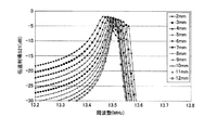
このように構成された送電装置及び受電装置により電力伝送の実験を行い、ベクトルネットワークアナライザ(以下VNAと略す)を用いて、伝送利得S21と反射利得S11を測定した。測定結果を、図3及び図4に示す。図3は、伝送利得S21の測定結果、図4は、反射利得S11の測定結果を示す。横軸は周波数(MHz)、縦軸は利得(dB)である。各曲線は、送電装置の共振コイルと受電装置の共振コイルのコイル間距離d(mm)を2mmから12mmまで、それぞれ異ならせて測定した結果を示す。 An experiment of power transmission was performed using the power transmission device and the power reception device configured as described above, and the transmission gain S21 and the reflection gain S11 were measured using a vector network analyzer (hereinafter abbreviated as VNA). The measurement results are shown in FIGS. FIG. 3 shows the measurement result of the transmission gain S21, and FIG. 4 shows the measurement result of the reflection gain S11. The horizontal axis represents frequency (MHz) and the vertical axis represents gain (dB). Each curve shows the measurement result obtained by varying the distance d (mm) between the resonance coil of the power transmission device and the resonance coil of the power reception device from 2 mm to 12 mm.
図3及び図4から判るように、コイル間距離dが9mmで臨界結合となり、それよりも距離が離れると疎結合となって利得が減少する。一方、臨界結合距離よりも近づくと密結合となり、利得のピークが、13.56MHzよりも低周波数側と高周波側に分離してしまう。距離2mmまで近づけると、低周波数側は11.9MHzまで低下した。 As can be seen from FIGS. 3 and 4, critical coupling occurs when the distance d between the coils is 9 mm, and loose coupling occurs when the distance is longer than that, and the gain decreases. On the other hand, when the distance is closer than the critical coupling distance, tight coupling occurs, and the gain peak is separated into a lower frequency side and a higher frequency side than 13.56 MHz. When approaching to a distance of 2 mm, the low frequency side decreased to 11.9 MHz.
さらに、図1の送電側共振コイル装置11と受電側共振コイル装置12のように、図2のキャパシタ20のような構成を有する集中定数キャパシタ13、15を付加するとともに、共振コイル4、5に直列に、集中定数インダクタ14、16(L=5μH)を接続した。構成された送電装置9及び受電装置10により電力伝送の実験を行い、VNAで伝送利得S21と反射利得S11を測定した。測定結果を図5及び図6に示す。図5は、伝送利得S21の測定結果、図6は、反射利得S11の測定結果を示す。横軸は周波数(MHz)、縦軸は利得(dB)である。各曲線は、送電側共振コイル4と受電側共振コイル5のコイル間距離d(mm)を2mmから12mmまで、それぞれ異ならせて測定した結果を示す。
Further, lumped
図5及び図6から判るように、コイル間距離dが9mmで臨界結合となり、インダクタを設ける前後で変化しない。一方で密結合時の周波数の変化は、距離dが2mmとなるまで近づけても、低周波数側は13.45MHzと、周波数変化量は大幅に縮小される。また、結合係数kは集中定数インダクタの追加で小さくなるが、Q値は大きくなるので、結果として伝送効率はほとんど変化しない。すなわち、見かけのQ値を大きくして、コイル間距離が短い密結合状態における利得最大周波数の変動幅を小さく抑えることができる。 As can be seen from FIGS. 5 and 6, critical coupling occurs when the distance d between the coils is 9 mm, and does not change before and after the inductor is provided. On the other hand, even if the frequency change at the time of tight coupling is close until the distance d reaches 2 mm, the frequency change amount is greatly reduced to 13.45 MHz on the low frequency side. Further, although the coupling coefficient k is decreased by adding a lumped constant inductor, the Q value is increased, and as a result, the transmission efficiency hardly changes. That is, the apparent Q value can be increased, and the fluctuation range of the maximum gain frequency in the tightly coupled state where the distance between the coils is short can be suppressed small.
上記効果を十分に得るためには、集中定数インダクタ14、16のインダクタンスおよび集中定数キャパシタ13、15のキャパシタンスは、送電側共振コイル装置11のインダクタンスと受電側共振コイル装置12のインダクタンスが等しく、かつ送電側共振コイル装置11のキャパシタンスと受電側共振コイル装置12のキャパシタンスが等しくなるように設定されることが望ましい。
In order to sufficiently obtain the above effect, the inductances of the lumped
以上の構成により、共振周波数の補正幅を小さくできるので、周波数幅の狭いISMバンドにも、磁界共鳴による電力伝送を容易に適用可能となる。 With the above configuration, the correction width of the resonance frequency can be reduced, so that power transmission by magnetic field resonance can be easily applied to an ISM band having a narrow frequency width.
本発明の非接触電力伝送装置は、共振コイル間距離が短い密結合状態における周波数の変動幅を小さく抑えることが可能であり、携帯電話やデジタルカメラ等のモバイル機器、TVや電気自動車などへの非接触電力伝送装置に好適である。 The contactless power transmission device of the present invention can suppress the fluctuation range of the frequency in a tightly coupled state where the distance between the resonance coils is short, and can be applied to mobile devices such as mobile phones and digital cameras, TVs and electric vehicles. It is suitable for a non-contact power transmission device.
1、9 送電装置
2、10 受電装置
3 送電側給電コイル
4 送電側共振コイル
5 受電側共振コイル
6 受電側給電コイル
7 発振器
8 負荷
11 送電側共振コイル装置
12 受電側共振コイル装置
13、15 集中定数キャパシタ
14、16 集中定数インダクタ
18 コイル
19a、19b 配線
20 キャパシタ
DESCRIPTION OF
Claims (4)
前記送電側共振コイルおよび前記受電側共振コイルの共振周波数と等しい周波数の電力を前記送電側共振コイルに供給して励振し、前記送電側共振コイルと前記受電側共振コイルとの間の磁界共鳴現象により電力を伝送して前記受電側給電コイルから電力を取り出す非接触電力伝送装置において、
前記送電側共振コイルに集中定数インダクタおよび集中定数キャパシタが付加された送電側共振コイル装置、または
前記受電側共振コイルに集中定数インダクタおよび集中定数キャパシタが付加された受電側共振コイル装置の少なくとも一方が構成されていることを特徴とする非接触電力伝送装置。 A power transmission device having a power transmission side power supply coil and a power transmission side resonance coil, and a power reception device having a power reception side power supply coil and a power reception side resonance coil,
Magnetic field resonance phenomenon between the power transmission side resonance coil and the power reception side resonance coil by supplying power to the power transmission side resonance coil with excitation having the same frequency as the resonance frequency of the power transmission side resonance coil and the power reception side resonance coil. In a non-contact power transmission device that transmits power from and extracts power from the power receiving coil,
At least one of a power transmission side resonance coil device in which a lumped constant inductor and a lumped constant capacitor are added to the power transmission side resonance coil, or a power reception side resonance coil device in which a lumped constant inductor and a lumped constant capacitor are added to the power reception side resonance coil, It is comprised, The non-contact electric power transmission apparatus characterized by the above-mentioned.
前記送電側共振コイルおよび前記受電側共振コイルの共振周波数と等しい周波数の電力を前記送電側共振コイルに供給して励振し、前記送電側共振コイルと前記受電側共振コイルとの間の磁界共鳴現象により電力を伝送して前記受電側給電コイルから電力を取り出す非接触電力伝送に用いられる前記送電装置において、
前記送電側共振コイルに集中定数インダクタおよび集中定数キャパシタが付加されていることを特徴とする送電装置。 Using a power transmission device having a power transmission side power supply coil and a power transmission side resonance coil, and a power reception device having a power reception side power supply coil and a power reception side resonance coil,
Magnetic field resonance phenomenon between the power transmission side resonance coil and the power reception side resonance coil by supplying power to the power transmission side resonance coil with excitation having the same frequency as the resonance frequency of the power transmission side resonance coil and the power reception side resonance coil. In the power transmission device used for non-contact power transmission that transmits power by extracting power from the power receiving side feeding coil,
A power transmission device, wherein a lumped constant inductor and a lumped constant capacitor are added to the power transmission side resonance coil.
前記送電側共振コイルおよび前記受電側共振コイルの共振周波数と等しい周波数の電力を前記送電側共振コイルに供給して励振し、前記送電側共振コイルと前記受電側共振コイルとの間の磁界共鳴現象により電力を伝送して前記受電側給電コイルから電力を取り出す非接触電力伝送に用いられる前記受電装置において、
前記受電側共振コイルに集中定数インダクタおよび集中定数キャパシタが付加されていることを特徴とする送電装置。 Using a power transmission device having a power transmission side power supply coil and a power transmission side resonance coil, and a power reception device having a power reception side power supply coil and a power reception side resonance coil,
Magnetic field resonance phenomenon between the power transmission side resonance coil and the power reception side resonance coil by supplying power to the power transmission side resonance coil with excitation having the same frequency as the resonance frequency of the power transmission side resonance coil and the power reception side resonance coil. In the power receiving device used for non-contact power transmission that transmits electric power and extracts power from the power receiving coil.
A power transmission apparatus, wherein a lumped constant inductor and a lumped constant capacitor are added to the power receiving side resonance coil.
Priority Applications (1)
| Application Number | Priority Date | Filing Date | Title |
|---|---|---|---|
| JP2011051160A JP2012191697A (en) | 2011-03-09 | 2011-03-09 | Non-contact power transmission apparatus |
Applications Claiming Priority (1)
| Application Number | Priority Date | Filing Date | Title |
|---|---|---|---|
| JP2011051160A JP2012191697A (en) | 2011-03-09 | 2011-03-09 | Non-contact power transmission apparatus |
Publications (1)
| Publication Number | Publication Date |
|---|---|
| JP2012191697A true JP2012191697A (en) | 2012-10-04 |
Family
ID=47084288
Family Applications (1)
| Application Number | Title | Priority Date | Filing Date |
|---|---|---|---|
| JP2011051160A Pending JP2012191697A (en) | 2011-03-09 | 2011-03-09 | Non-contact power transmission apparatus |
Country Status (1)
| Country | Link |
|---|---|
| JP (1) | JP2012191697A (en) |
Cited By (3)
| Publication number | Priority date | Publication date | Assignee | Title |
|---|---|---|---|---|
| JP2016082670A (en) * | 2014-10-15 | 2016-05-16 | 学校法人加計学園 岡山理科大学 | Non-contact power supply device |
| US9818532B2 (en) | 2012-12-07 | 2017-11-14 | Nitto Denko Corporation | Method of forming electromagnetic space |
| KR20180027345A (en) * | 2016-09-05 | 2018-03-14 | 가부시끼가이샤 도시바 | Filter circuit and wireless power transfer system |
Citations (6)
| Publication number | Priority date | Publication date | Assignee | Title |
|---|---|---|---|---|
| WO2009037821A1 (en) * | 2007-09-17 | 2009-03-26 | Hideo Kikuchi | Induced power transmission circuit |
| JP2010068657A (en) * | 2008-09-11 | 2010-03-25 | Yazaki Corp | Wireless power transmitting device and resonance frequency adjustment method |
| JP2010130878A (en) * | 2008-12-01 | 2010-06-10 | Toyota Industries Corp | Contactless power transmission system |
| JP2010158151A (en) * | 2008-12-01 | 2010-07-15 | Toyota Industries Corp | Contactless power transmission apparatus |
| JP2010239769A (en) * | 2009-03-31 | 2010-10-21 | Fujitsu Ltd | Wireless power supply system |
| JP2011087433A (en) * | 2009-10-16 | 2011-04-28 | Tdk Corp | Wireless power-supply device, wireless power-receiving device, and wireless power transmission system |
-
2011
- 2011-03-09 JP JP2011051160A patent/JP2012191697A/en active Pending
Patent Citations (6)
| Publication number | Priority date | Publication date | Assignee | Title |
|---|---|---|---|---|
| WO2009037821A1 (en) * | 2007-09-17 | 2009-03-26 | Hideo Kikuchi | Induced power transmission circuit |
| JP2010068657A (en) * | 2008-09-11 | 2010-03-25 | Yazaki Corp | Wireless power transmitting device and resonance frequency adjustment method |
| JP2010130878A (en) * | 2008-12-01 | 2010-06-10 | Toyota Industries Corp | Contactless power transmission system |
| JP2010158151A (en) * | 2008-12-01 | 2010-07-15 | Toyota Industries Corp | Contactless power transmission apparatus |
| JP2010239769A (en) * | 2009-03-31 | 2010-10-21 | Fujitsu Ltd | Wireless power supply system |
| JP2011087433A (en) * | 2009-10-16 | 2011-04-28 | Tdk Corp | Wireless power-supply device, wireless power-receiving device, and wireless power transmission system |
Cited By (3)
| Publication number | Priority date | Publication date | Assignee | Title |
|---|---|---|---|---|
| US9818532B2 (en) | 2012-12-07 | 2017-11-14 | Nitto Denko Corporation | Method of forming electromagnetic space |
| JP2016082670A (en) * | 2014-10-15 | 2016-05-16 | 学校法人加計学園 岡山理科大学 | Non-contact power supply device |
| KR20180027345A (en) * | 2016-09-05 | 2018-03-14 | 가부시끼가이샤 도시바 | Filter circuit and wireless power transfer system |
Similar Documents
| Publication | Publication Date | Title |
|---|---|---|
| JP5172050B2 (en) | Wireless power transmission device | |
| JP5573190B2 (en) | Wireless power supply system | |
| JP6288519B2 (en) | Wireless power transmission system | |
| JP6097215B2 (en) | Wireless power transmission apparatus and multiband resonant power transmission method thereof | |
| CN103414261B (en) | Variable-coupling coefficient magnetic resonance wireless power transmission system and method | |
| US20130009488A1 (en) | Non-contact power transmission device and near-field antenna for same | |
| US10158254B2 (en) | Resonant coupling power transmission system, resonance type power transmission device, and resonance type power reception device | |
| WO2011125328A1 (en) | Wireless power transmission system | |
| US20120217820A1 (en) | Wireless power transmission system and resonator for the system | |
| WO2013080531A1 (en) | Wireless power transmission device | |
| CN104993614A (en) | Asymmetric wireless power transmission system with relay coil inserted therein, and method | |
| KR20130040628A (en) | Wireless power transmission apparatus | |
| WO2017056343A1 (en) | Wireless power transmission system and power transmission device | |
| CN104521100B (en) | Contactless power transmission device, electric supply installation and current-collecting device | |
| JP6108310B2 (en) | Wireless power transmission device | |
| JP2013542700A (en) | RESONANT POWER TRANSMITTING SYSTEM POWER CONVERTER AND RESONANT POWER TRANSMITTING DEVICE | |
| JP2012191697A (en) | Non-contact power transmission apparatus | |
| JP2012034524A (en) | Wireless power transmission apparatus | |
| Jolani et al. | A novel planar wireless power transfer system with strong coupled magnetic resonances | |
| Lim et al. | Size-adjustable coils for compensation of lateral misalignment in WPT systems | |
| US10491043B2 (en) | Resonant coil, wireless power transmitter using the same, wireless power receiver using the same | |
| JP2012085234A (en) | Transmission system and transmission device | |
| KR20120116801A (en) | A wireless power transmission circuit, a wireless power transmitter and receiver | |
| CN110729975A (en) | Magnetic coupling resonant wireless power transmission power amplification system | |
| JP2013081331A (en) | Non-contact power transmission apparatus |
Legal Events
| Date | Code | Title | Description |
|---|---|---|---|
| A711 | Notification of change in applicant |
Free format text: JAPANESE INTERMEDIATE CODE: A712 Effective date: 20130123 |
|
| A621 | Written request for application examination |
Free format text: JAPANESE INTERMEDIATE CODE: A621 Effective date: 20140218 |
|
| A977 | Report on retrieval |
Free format text: JAPANESE INTERMEDIATE CODE: A971007 Effective date: 20141010 |
|
| A02 | Decision of refusal |
Free format text: JAPANESE INTERMEDIATE CODE: A02 Effective date: 20150305 |