JP2012190405A - Route information correcting device, track planning device, and robot - Google Patents
Route information correcting device, track planning device, and robot Download PDFInfo
- Publication number
- JP2012190405A JP2012190405A JP2011055483A JP2011055483A JP2012190405A JP 2012190405 A JP2012190405 A JP 2012190405A JP 2011055483 A JP2011055483 A JP 2011055483A JP 2011055483 A JP2011055483 A JP 2011055483A JP 2012190405 A JP2012190405 A JP 2012190405A
- Authority
- JP
- Japan
- Prior art keywords
- node
- interference
- route
- unit
- additional
- Prior art date
- Legal status (The legal status is an assumption and is not a legal conclusion. Google has not performed a legal analysis and makes no representation as to the accuracy of the status listed.)
- Withdrawn
Links
- 238000012937 correction Methods 0.000 claims description 66
- 238000000034 method Methods 0.000 claims description 40
- 230000002452 interceptive effect Effects 0.000 claims description 25
- 238000012545 processing Methods 0.000 claims description 20
- 230000007613 environmental effect Effects 0.000 claims description 6
- 238000010586 diagram Methods 0.000 description 22
- 230000036544 posture Effects 0.000 description 18
- 238000012790 confirmation Methods 0.000 description 7
- 230000006870 function Effects 0.000 description 6
- 230000004044 response Effects 0.000 description 3
- 239000000470 constituent Substances 0.000 description 2
- 238000012217 deletion Methods 0.000 description 2
- 230000037430 deletion Effects 0.000 description 2
- 230000000694 effects Effects 0.000 description 2
- 238000007689 inspection Methods 0.000 description 2
- 238000005259 measurement Methods 0.000 description 2
- 238000005516 engineering process Methods 0.000 description 1
- 238000009499 grossing Methods 0.000 description 1
- 238000003384 imaging method Methods 0.000 description 1
- 238000000691 measurement method Methods 0.000 description 1
- 230000003287 optical effect Effects 0.000 description 1
- 238000004321 preservation Methods 0.000 description 1
- 239000013598 vector Substances 0.000 description 1
Images


Landscapes
- Control Of Position, Course, Altitude, Or Attitude Of Moving Bodies (AREA)
Abstract
Description
本発明は、経路情報修正装置、軌道計画装置、及びロボットに関する。 The present invention relates to a route information correction device, a trajectory planning device, and a robot.
2次元/3次元空間におけるロボットの移動経路を算出する技術の進展が著しい。 Advances in technology for calculating the movement path of a robot in a two-dimensional / three-dimensional space are remarkable.
特許文献1には、同文献の段落0017に記載のように、地図生成部12で生成された地図情報に対し、コーナー経路情報生成部16が出力する情報を付加してグラフ表現の地図情報を修正する点が開示されている。なお、地図情報とは、同文献の段落0015に記載のように、ノード、エッジからなるグラフ表現である。また、同文献の段落0015には、軌道計画部13は、地図生成部12が生成した地図情報及びユーザより与えられる移動開始地点及び目的地の位置情報に基づいて、目的地までの経路情報を探索して経路列を生成する、と記載されている。同文献の段落0020には、ノード情報には、図3に定義されるコーナー環境情報が含まれる点が記載されている。同文献の段落0021には、同文献の図4乃至6を参照して算出処理する点が開示されている。同文献の段落0028には、ステップ8までで求めた、通過領域、円弧経路中心位置および円弧経路終了点における移動ロボットの姿勢をノード情報に登録する、と記載されている。これらによって、より最適な経路を求めることが可能になる点が開示されている。
In
特許文献2には、ロボットの移動経路の算出に関する一例が開示されている。特許文献2の図4に示すように、現在位置と目標位置間の間には、RRT(Rapidly-exploring Random Tree)により算出された複数のノードが設けられている。特許文献2の図4に示すように、ノード間は、バネ及びダンパにより接続され、ノード間に引力が作用し、軌跡が滑らかになる点が開示されている(例えば、特許文献1の段落0044参照)。
ノード間がエッジにより接続されたグラフ構造のロードマップを探索して経路を求める場合、予め用意されるノードが有限であるため、ロボットの周囲の障害物の存在状態によっては、障害物と干渉するノードを含まない非干渉経路を求めることが容易ではない場合があり得る。このように、障害物と干渉するノードを含まない非干渉経路の算出確率を高めることが強く望まれている。 When searching for a road map with a graph structure in which nodes are connected by edges, the paths prepared in advance intervene with obstacles depending on the presence of obstacles around the robot because the number of nodes prepared in advance is limited. It may not be easy to find a non-interfering path that does not include a node. Thus, it is strongly desired to increase the calculation probability of a non-interference path that does not include a node that interferes with an obstacle.
本発明に係る経路情報修正装置は、エッジを介したノード間の接続により構成される経路情報を修正する経路情報修正装置であって、環境情報に基づいて前記経路情報に含まれる前記ノードの干渉性を判定する干渉判定部と、前記干渉判定部により干渉有りと判定された前記ノードの周囲に追加ノードを生成する追加ノード生成部と、前記干渉判定部による前記追加ノードの干渉性の判定結果に応じて、干渉有りと判定された前記ノードを前記追加ノードに置き換えるノード置換実行部と、を備える。 A path information correction apparatus according to the present invention is a path information correction apparatus that corrects path information configured by connection between nodes via an edge, and includes interference of the node included in the path information based on environment information An interference determination unit that determines the nature of the additional node, an additional node generation unit that generates an additional node around the node determined to have interference by the interference determination unit, and a determination result of the coherence of the additional node by the interference determination unit And a node replacement execution unit that replaces the node determined to have interference with the additional node.
前記干渉判定部は、前記干渉有りと判定された前記ノードにエッジを介して隣接するノードも干渉有りと判定されたか否かを判定し、前記追加ノード生成部は、連続しない態様にて干渉している前記ノードの周囲に前記追加ノードを生成する、と良い。 The interference determination unit determines whether a node adjacent to the node determined to have interference through an edge is also determined to have interference, and the additional node generation unit interferes in a non-continuous manner. The additional node may be generated around the node that is present.
前記干渉判定部は、前記干渉有りと判定された前記ノードにエッジを介して隣接するノードも干渉有りと判定されたか否かを判定する、上記の経路情報修正装置であって、当該経路情報修正装置は、前記干渉判定部により、前記干渉有りと判定された前記ノードにエッジを介して隣接するノードも干渉有りと判定された場合、連続的に干渉している各ノード及び当該ノードらに接続されたエッジの削除を指示する。 The interference determination unit is the above-described route information correction device that determines whether or not a node adjacent to the node determined to have the interference via an edge is also determined to have interference, the route information correction When the interference determination unit determines that the node adjacent to the node determined to have interference is also determined to have interference by the interference determination unit, the device is connected to each node that is continuously interfering and the nodes. Instructs the deletion of the specified edge.
前記干渉判定部は、前記干渉有りと判定された前記ノードにエッジを介して隣接するノードも干渉有りと判定されたか否かを判定する、上記いずれかの経路情報修正装置であって、当該経路情報修正装置は、前記干渉判定部により連続しない態様にて干渉していると判定された前記ノードに至るエッジのコストの増加を指示する。 The interference determination unit according to any one of the above-described route information correction devices, which determines whether or not a node adjacent to the node determined to have the interference via an edge is also determined to have interference. The information correction apparatus instructs an increase in the cost of the edge reaching the node determined to be interfering in a non-continuous manner by the interference determination unit.
前記経路情報同士の一致性を判定する比較判定部を更に備え、前記追加ノード生成部は、前記比較判定部によって時間的に連続して探索された前記経路情報同士が一致すると判定されたとき、前記干渉判定部により干渉有りと判定された前記ノードに基づいて前記追加ノードを生成する、と良い。 A comparison / determination unit that determines the match between the route information; and when the additional node generation unit determines that the route information searched continuously in time by the comparison / determination unit matches, The additional node may be generated based on the node determined to have interference by the interference determination unit.
前記経路情報同士の一致性を判定する比較判定部を更に備え、前記追加ノード生成部は、前記比較判定部によって時間的に連続する前記経路情報同士が一致すると判定されたとき、前記干渉判定部により干渉有りと判定された前記ノードに基づいて前記追加ノードを生成する上記いずれかに記載の経路情報修正装置であって、前記追加ノード生成部は、所定数の前記追加ノードを生成し、前記干渉判定部は、所定数の前記追加ノードに含まれる前記追加ノードの干渉性を順に判定する、と良い。 The interference determination unit further includes a comparison determination unit that determines matching between the route information, and the additional node generation unit determines that the route information that is temporally continuous matches by the comparison determination unit. The route information correction device according to any one of the above, wherein the additional node is generated based on the node determined to have interference by the additional node generation unit, wherein the additional node generation unit generates a predetermined number of the additional nodes, and The interference determination unit may sequentially determine the coherence of the additional nodes included in the predetermined number of the additional nodes.
前記追加ノード生成部は、所定関数の実行に基づいて、複数の前記追加ノードを生成する、と良い。前記ノードは、複数の値から構成される、と良い。前記ノード置換実行部によって処理された前記経路情報に対して経路補間処理を実行する補間処理部を更に備え、前記補間処理部は、前記経路情報に含まれる経路に対して所定間隔で離散点を設け、前記干渉判定部は、前記環境情報に基づいて前記離散点の干渉性を判定する、と良い。 The additional node generation unit may generate a plurality of the additional nodes based on execution of a predetermined function. The node is preferably composed of a plurality of values. The image processing apparatus further includes an interpolation processing unit that performs a route interpolation process on the route information processed by the node replacement execution unit, and the interpolation processing unit sets discrete points at predetermined intervals with respect to the route included in the route information. It is preferable that the interference determination unit determine the coherence of the discrete points based on the environment information.
本発明に係る軌道計画装置は、コスト設定されたエッジを介して複数のノードが接続されたロードマップ情報を記憶するロードマップ記憶部と、前記ロードマップ情報から得られるコスト情報の処理に基づいて、スタート及びゴールノード間の経路を探索する経路探索部と、前記経路探索部から供給される前記経路情報を修正する上記いずれかに記載の経路情報修正装置と、を備える。前記環境情報を取得する環境情報取得部を更に備える、と良い。 The trajectory planning apparatus according to the present invention is based on a road map storage unit that stores road map information in which a plurality of nodes are connected via cost-set edges, and processing of cost information obtained from the road map information. A route search unit that searches for a route between the start and goal nodes, and the route information correction device according to any one of the above that corrects the route information supplied from the route search unit. It is good to further have an environment information acquisition part which acquires the environment information.
本発明に係るロボットは、上記した軌道計画装置を内蔵する。 The robot according to the present invention incorporates the trajectory planning apparatus described above.
本発明に係る経路情報修正装置は、エッジを介したノード間の接続により構成される経路情報を修正する経路情報修正装置の動作方法であって、環境情報に基づいて前記経路情報に含まれる前記ノードの干渉性を判定し、前記判定により干渉有りと判定された前記ノードの周囲に追加ノードを生成し、前記判定による前記追加ノードの干渉性の判定結果に応じて、干渉有りと判定された前記ノードを前記追加ノードに置き換える。 The path information correction apparatus according to the present invention is an operation method of a path information correction apparatus that corrects path information configured by connection between nodes via edges, and is included in the path information based on environment information. Determine the coherence of the node, generate an additional node around the node determined to have interference by the determination, and determine that there is interference according to the determination result of the interference of the additional node by the determination Replace the node with the additional node.
本発明に係るプログラムは、上記の動作方法をコンピュータに実行させる。 A program according to the present invention causes a computer to execute the operation method described above.
本発明によれば、障害物と干渉するノードを含まない非干渉経路の算出確率を高めることができる。 According to the present invention, it is possible to increase the calculation probability of a non-interference path that does not include a node that interferes with an obstacle.
以下、図面を参照して実施の形態について説明する。なお、各実施の形態は、個々に独立したものではなく、互いに組み合わせ可能であり、また、その組み合わせに基づく効果も主張可能なものとする。図面は、説明のために用いられており、適宜、簡略化されている。 Hereinafter, embodiments will be described with reference to the drawings. Each embodiment is not individually independent but can be combined with each other, and an effect based on the combination can be claimed. The drawings are used for explanation and are simplified as appropriate.
実施の形態1
本実施形態に係る軌道計画装置100(図1参照)は、エッジを介したノード間の接続により構成される経路データを修正するものであり、環境情報に基づいて経路データに含まれるノードの干渉性を判定し、干渉有りと判定されたノード(以下、単に干渉ノードと呼ぶ場合がある)の周囲に追加ノードを生成し、追加ノードの干渉性の判定結果に応じて、元の干渉ノードを非干渉の追加ノードに置き換える(図10参照:干渉ノードq3が非干渉の追加ノードqn5に置き換えられている)。干渉ノードが非干渉の追加ノードに置きかえられて代替経路が提供されることによって、経路中に干渉ノードを含まない非干渉経路の算出確率を効果的に高めることができる。干渉ノードの周囲に追加ノードを設定することによって、多数のノードを事前に用意する必要を回避できる。ロボットの周囲環境が任意/随時に変化し、かつ、ロボットの移動態様の自由度が大きい場合であっても、その場の環境に応じて、適宜、ノード配置状態を修正することができ、非干渉経路の算出確率を効果的に高めることができる。なお、非干渉のノードとは、補足説明すれば、障害物に対してノードが干渉していないノードである。障害物に対してノードが干渉するか否かの判断手法/判断基準は任意であり、それは、軌道計画装置100が組み込まれる装置に応じて適宜調整される。
The trajectory planning apparatus 100 (see FIG. 1) according to the present embodiment corrects route data configured by connection between nodes via edges, and interference of nodes included in the route data based on environment information. And generating an additional node around a node determined to have interference (hereinafter, simply referred to as an interference node), and depending on the determination result of the interference of the additional node, the original interference node is Replacement with a non-interfering additional node (see FIG. 10: the interfering node q3 is replaced with a non-interfering additional node qn5). By replacing the interfering node with a non-interfering additional node and providing an alternative path, it is possible to effectively increase the calculation probability of a non-interfering path that does not include the interfering node in the path. By setting an additional node around the interference node, it is possible to avoid the necessity of preparing a large number of nodes in advance. Even if the surrounding environment of the robot changes arbitrarily / as needed, and the degree of freedom of movement of the robot is large, the node arrangement state can be appropriately corrected according to the environment of the place. It is possible to effectively increase the calculation probability of the interference path. Note that the non-interfering node is a node in which the node does not interfere with the obstacle, if it is supplementarily described. The determination method / criteria for determining whether or not a node interferes with an obstacle is arbitrary, and is appropriately adjusted according to the apparatus in which the
なお、膨大な数のノードを事前に用意することでも非干渉経路の算出確率を高めることができる。しかしながら、この場合、ノード数及びエッジ数が増加するため、経路探索処理に要する計算コストが増大してしまうおそれがあり、全体としてのパフォーマンスを向上させることは難しくなるおそれがある。なお、計算コストとは、経路探索において解を求めることに要する計算処理の程度を示す。計算コストが大きい場合には、多量の計算処理が必要になる。計算コストが小さい場合には、少量の計算処理で済む。 Note that the probability of calculating a non-interfering path can also be increased by preparing a huge number of nodes in advance. However, in this case, since the number of nodes and the number of edges increase, the calculation cost required for the route search process may increase, and it may be difficult to improve the overall performance. The calculation cost indicates the degree of calculation processing required for obtaining a solution in route search. When the calculation cost is high, a large amount of calculation processing is required. When the calculation cost is small, a small amount of calculation processing is sufficient.
以下、図面を参照しつつ具体的に説明する。なお、以下では、多関節ロボットアームの軌道を計画することを念頭において説明するが、本願発明は、これに限らず、他の軌道計画(例えば、ロボットが空間移動する際の軌道計画)に適用しても良い。算出される軌道は、2次元/3次元空間のいずれに適用され得る。軌道上のノードにより指標される情報は、任意であり、軌道が適用される装置等に応じて適宜設定される。以下では、情報とデータとを区別することなく説明する場合がある。 Hereinafter, it demonstrates concretely, referring drawings. In the following, the description will be made in consideration of planning the trajectory of the articulated robot arm. However, the present invention is not limited to this, and is applicable to other trajectory plans (for example, the trajectory plan when the robot moves in space). You may do it. The calculated trajectory can be applied to either a two-dimensional / 3-dimensional space. The information indexed by the nodes on the trajectory is arbitrary and is set as appropriate according to the device to which the trajectory is applied. In the following description, information and data may be described without being distinguished.
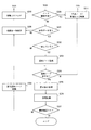
図1は、軌道計画装置の概略的なブロック図である。図2及び図3は、軌道計画装置の動作を示す概略的なフローチャートである。図4乃至図6は、探索された経路を示す模式図である。図7は、探索された経路及び経路データを示す模式図である。図8は、エッジに付加されるコストの増加処理を示す模式図である。図9は、追加ノードの生成/追加のノードの干渉確認処理を示す模式図である。図10は、干渉ノードを追加ノードに置き換える処理を示す模式図である。図11は、補間処理を示す模式図である。 FIG. 1 is a schematic block diagram of a trajectory planning apparatus. 2 and 3 are schematic flowcharts showing the operation of the trajectory planning apparatus. 4 to 6 are schematic diagrams showing the searched routes. FIG. 7 is a schematic diagram showing the searched route and route data. FIG. 8 is a schematic diagram showing a process of increasing the cost added to the edge. FIG. 9 is a schematic diagram illustrating generation of an additional node / interference confirmation processing of the additional node. FIG. 10 is a schematic diagram illustrating a process of replacing an interference node with an additional node. FIG. 11 is a schematic diagram illustrating the interpolation processing.
図1に示すように、軌道計画装置100は、ロードマップ記憶部10、経路供給部20、環境情報取得部30、経路修正部40、軌道補間部50、経路一致判定部60、および追加ノード生成部70を含む。経路供給部20は、ロードマップ一時記憶部22、ノード探索部24、および経路探索部26を含む。経路修正部40は、干渉判定部42、及びノード置換実行部44を含む。経路一致判定部60は、経路一時記憶部62、及び経路比較部64を含む。ロードマップ一時記憶部22は、ロードマップを記憶するという意味においてロードマップ記憶部10と同等であるため、ロードマップ記憶部と単に把握する場合もある。
As shown in FIG. 1, the
軌道計画装置100は、ロボットに組み込まれている。より具体的には、ロードマップ記憶部10を除いた計算機部分80と環境情報取得部30がロボットに組み込まれている。ロードマップ記憶部10は、当該ロボットに対して、ネットワーク接続されている。適当なタイミングで所要のロードマップデータがネットワークを介してロボットのロードマップ一時記憶部22にダウンロードされる。
The
軌道計画装置100は、コンピュータにより構成され、CPU(Central Processing Unit)等の演算処理器がメモリ等の記憶装置に記憶されたプログラムを実行することによって所定の機能を発揮する。プログラムの実行過程では、RAM(Random Access Memory)等に様々なデータが書き込まれ、CPUによる演算処理に用いられたりする。CPUとRAM間は、バス等を介して接続され、当該バスには、RAM等のメモリアクセスを制御するメモリコントローラも接続される。なお、コンピュータの具体的なアーキテクチャは任意である。軌道計画装置100を構成するコンピュータに対してインストールされるプログラムは、適宜、ハードディスク、光学記憶媒体(CD、DVD、BD等)等の任意の記憶手段に記憶される。
The
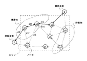
ロードマップ記憶部10は、グラフ構造のロードマップを記憶する記憶措置である。グラフ構造のロードマップは、エッジ(枝と呼ぶ場合もある)を介して多数のノード(頂点と呼ぶ場合もある)が接続されたデータである。グラフ構造のロードマップは、図4に示されている。但し、図4では、ロードマップ記憶部10からロードマップ一時記憶部22にダウンロードされた部分的なロードマップである。ロードマップ記憶部10に記憶されたロードマップは、ダウンロードされたロードマップよりもノード及びエッジ数が比較にならないほど多い。
The road
ノードは、ロボットアームの姿勢を示す。ロボットアームのモーター軸数がNのとき、ノードqcは、次式から明らかなように、関節角ベクトルqc1〜qcNによって表現される。
qc=(qc1,qc2,・・・,qcN) ・・・式(1)
The node indicates the posture of the robot arm. When the number of motor axes of the robot arm is N, the node q c is expressed by joint angle vectors q c1 to q cN as is apparent from the following equation.
q c = (q c1 , q c2 ,..., q cN ) (1)
エッジは、ノード間を接続し、ノード間の接続関係を示す。ノード間のノルム(距離と呼ぶ場合がある)が閾値以下/閾値未満のとき、それらのノード間にはエッジが接続される。エッジには、コストが付与されている。経路探索は、エッジに付与されたコストの演算処理によって実行される。例えば、コストの加算値が最少の経路が経路候補として算出される。コストは、例えば、姿勢変化に要求されるエネルギー量、時間等に応じて付与される。 An edge connects nodes and indicates a connection relationship between nodes. When the norm between nodes (sometimes called distance) is less than or less than a threshold value, an edge is connected between those nodes. Cost is given to the edge. The route search is executed by calculating the cost given to the edge. For example, a route having the smallest cost addition value is calculated as a route candidate. The cost is given according to, for example, the amount of energy and time required for posture change.
ロードマップ記憶部10に記憶されるロードマップの生成方法は任意である。例えば、ノードの表現式、エッジの生成条件等の各種条件をコンピュータに入力することによってコンピュータによって自動生成される。
A method for generating a road map stored in the road
経路供給部20は、初期姿勢及び最終姿勢に基づいて、それらの間を接続する経路を決定して供給する。なお、初期姿勢及び最終姿勢は、任意の手段によって算出されて、経路供給部20に供給されるものとする。初期姿勢及び最終姿勢は、例えば、ノードと同様に、式(1)によって表現される。
The
ロードマップ一時記憶部22には、ロードマップ記憶部10に記憶されたロードマップが部分的にダウンロードされたデータを記憶する。ロードマップ一時記憶部22に記憶されたロードマップは、ノード探索部24と経路探索部26へ供給される。後述の説明から明らかなように、ロードマップ一時記憶部22にロードマップを一時的に記憶することによって、ロードマップ一時記憶部22に記憶されたロードマップ自体を修正することが可能になる。例えば、不要なノードの削除、不要なエッジの削除が可能になる。これによって、異なる条件下において、経路探索部26によって再度経路探索することが可能となり、代替的な経路の迅速提供等が可能となる。
The road map
ノード探索部24は、初期姿勢に対応するノードをロードマップから探索する。同様に、最終姿勢に対応するノードをロードマップから探索する。探索処理後、ノード探索部24は、初期姿勢に対応するスタートノードと最終姿勢に対応するゴールノードとを経路探索部26へ出力する。
The
経路探索部26は、スタートノードとゴールノード間を接続する経路をロードマップから探索する。上述のように、ロードマップに含まれる各エッジにはコストが設定されている。経路探索部26は、エッジに付与されたコストの加算値が最小となる経路を求め、この経路を出力する。
The
環境情報取得部30は、ロボットアームの周囲環境の3次元計測を実行して、3次元データを取得するセンシング機能部である。3次元計測の具体的な手段は任意である。環境情報取得部30に含まれるセンサは、例えば、ステレオカメラ、レーザーレンジファインダ、又はデプスメジャーである。TOF(Time Of Flight)の原理に基づいて、前方の3次元状態を検出しても良い。なお、TOFに基づく測距方法は、検査光の発光タイミングから反射光の受光タイミング間の時間間隔を検知することによって、検査光の出射方向の奥行きを計測する方法である。ステレオカメラのように、複数の撮像系で取得した複数の画像の処理に基づいて奥行き情報を得ても良い。環境情報取得部30は、センサ出力により取得される3次元情報をモデル化し、モデル化したデータを経路修正部40に対して供給する。なお、モデル化は、例えば、検知された3次元形状に対して幾何モデルを適応することによって行われる。
The environment
経路修正部40は、後述の説明から明らかなように、経路修正処理に加えて、その他様々な処理を実行する。例えば、経路修正部40は、環境情報取得部30から供給されたデータに基づいて、経路供給部20から供給された経路に干渉ノードが含まれるか否かを判定する。経路修正部40は、ロードマップ一時記憶部22に対してノード及びエッジの削除を指示する。経路修正部40は、軌道補間部50に対して経路データを提供する。経路修正部40は、経路一時記憶部62に対して経路データを供給し、その書き込みを指示する。経路修正部40は、経路比較部64に対して、経路データを供給し、これと経路一時記憶部62に記憶された経路データとの比較を指示する。経路修正部40は、追加ノード生成部70から供給される経路データに含まれる追加ノードの干渉性を判断する。経路修正部40は、干渉ノードを非干渉の追加ノード置き換える処理も実行する。なお、経路修正部40の動作の詳細は、後述の説明から明らかになる。
As will be apparent from the following description, the
干渉判定部42は、経路供給部20から供給された経路に含まれるノードが、環境情報取得部30から供給されるデータから検知される障害物に対して干渉するか否かを判定する。干渉判定部42は、追加ノード生成部70から供給される経路に含まれる追加ノードが、環境情報取得部30から供給されるデータから検知される障害物に対して干渉するか否かを判定する。
The
ノード置換実行部44は、後述の説明から明らかなように、追加ノードの生成対象となった干渉ノードを非干渉の追加ノードに置き換える処理を実行する。ノード置換実行部44の動作の詳細は、後述の説明から明らかになる。
As will be apparent from the following description, the node
軌道補間部50は、経路を円滑化する処理をする。経路一致判定部60は、経路供給部20から連続して供給される経路が一致するか否かを判定する。経路一時記憶部62は、前回供給された経路を一時的に記憶する。経路比較部64は、今回供給された経路と前回供給された経路とを比較し、両者が一致するか否かを判定する。経路比較部64は、両者が一致するとき、その経路データを追加ノード生成部70へ出力し、両者が異なるとき、不一致信号を経路修正部40へ出力する。追加ノード生成部70は、対象となる干渉ノードの周囲に追加ノードを生成し、追加ノードが追加された経路を経路修正部40へ供給する。なお、軌道補間部50〜追加ノード生成部70の動作の詳細は、後述の説明から明らかになる。
The
図2及び図3を参照して、軌道計画装置100の動作手順について説明する。適宜、図4乃至図11を併せて参照して説明する。図4乃至図10では、実線が探索された経路を示し、破線が探索されなかった経路を示す。一点鎖線は、環境情報取得部30の出力から検知される障害物が存在する領域を示す。
The operation procedure of the
まず、環境情報を取得する(S100)。具体的には、環境情報取得部30は、センサ系を駆動して環境情報を取得し、取得データを情報処理して出力する。これによって、ロボットアームが可動する空間の障害物位置が検知される。
First, environmental information is acquired (S100). Specifically, the environmental
次に、軌道計画する(S101)。具体的には、経路供給部20は、初期及び最終姿勢間を接続する経路を探索する。ノード探索部24は、まず、初期姿勢に対応するノードを探索し、最終姿勢に対応するノードを探索し、そして、これらの探索により得られたスタート及びゴールノードを経路探索部26に供給する。経路探索部26は、コスト計算に基づいて、スタート及びゴールノード間を接続する経路を探索する。経路探索部26は、コストが最小となる経路を求め、これを経路修正部40へ出力する。なお、経路探索の具体的な手法は任意であり、コスト計算処理に基づく手法に限られるべきものではない。
Next, trajectory planning is performed (S101). Specifically, the
軌道計画が成功したとき(S102)、干渉チェックをする(S103)。 When the trajectory plan is successful (S102), an interference check is performed (S103).
軌道計画が成功しているか否かは、障害物に対するノードの干渉性を考慮することなく行われる。例えば、図4に模式的に示すように経路が探索された場合であっても、軌道計画が成功したものと判定される。なお、経路探索部26が経路の出力の有無によって、軌道計画が成功したか否かが決定される。
Whether or not the trajectory planning is successful is performed without considering the coherence of the node to the obstacle. For example, even when a route is searched as schematically shown in FIG. 4, it is determined that the trajectory plan is successful. Note that whether or not the trajectory plan is successful is determined based on whether or not the
経路探索部26から経路が供給されると、干渉判定部42は、その経路の構成ノードの干渉性を判定する(S103)。
When a route is supplied from the
今回探索された経路の構成ノードが障害物と干渉していない場合、補間処理(S104)が行われる。具体的には、軌道補間部50は、経路修正部40から供給される経路に対して一定間隔Δqで離散点を設ける(図11(a)参照)。
When the constituent node of the route searched this time does not interfere with the obstacle, an interpolation process (S104) is performed. Specifically, the
次に、最終確認をする(S105)。具体的には、干渉判定部42は、軌道補間部50から供給された経路上のノード及び離散点が障害物と干渉しているか否かを判定する(図11(b)の点参照)。離散点が障害物と干渉しているかを判定することによって、ロボットアームが障害物と接触することをより確実に回避することができる。また、経路修正部40は、ロボットアームが許容する条件(例えば、ロボットアームの関節の可動角度)を満足するか否かを判定する。ロボットアームの関節の可動角度以外の場合、ロボットアームは、その経路に沿って動き得ないため、このような無意味な経路を排除する。
Next, a final confirmation is made (S105). Specifically, the
最終確認がOKの場合、経路修正部40は、最終的な経路を軌道データとして出力する。最終確認がNGの場合、不要なエッジを削除する(S106)。不要なエッジは、例えば、障害物と干渉しているノードに至るエッジ、障害物と干渉している離散点が含まれるエッジ等である。経路修正部40は、ロードマップ一時記憶部22に対して、上述の不要なエッジを削除することを指示する。ロードマップ一時記憶部22は、経路修正部40からの指示によって、当該指示により特定されるエッジを削除する。一時的に記憶されたロードマップ自体を修正/変更することによって、軌道計画(S101)によって再び探索される経路がより的確なものとなる可能性を効果的に高めることができる。なお、スタートノードとゴールノード間を接続する経路が存在しない場合(S102)、軌道計画が失敗となる。
When the final confirmation is OK, the
障害物に対して干渉しているノードが経路に含まれるとき(S103)、追加処理(S107)へ移行する。この追加処理(S107)を経て、最終的な経路が生成され、又はS101へ戻ることになる。追加処理(S107)の詳細を図3に示す。 When a node that interferes with an obstacle is included in the route (S103), the process proceeds to an additional process (S107). Through this addition process (S107), a final route is generated or the process returns to S101. Details of the addition processing (S107) are shown in FIG.
図3に示すように、干渉チェックがNGのとき(S103)、ノードが連続して干渉しているか否かを判定する(S200)。具体的には、干渉判定部42は、エッジを介して連続するノード夫々が障害物に干渉しているか否かを判定する。
As shown in FIG. 3, when the interference check is NG (S103), it is determined whether or not the node continuously interferes (S200). Specifically, the
例えば、図4に示す経路が供給されると、干渉判定部42は、ノードq1が障害物に干渉していることを検知し(S103)、次に、ノードq3が障害物に干渉していることを検知する(S200)。
For example, when the route shown in FIG. 4 is supplied, the
ノードが連続して干渉しているとき、干渉ノード/関連エッジを削除する(S211)。具体的には、経路修正部40は、干渉ノード及びこれに接続されたエッジを除去することをロードマップ一時記憶部22に対して指示する。ロードマップ一時記憶部22は、経路修正部40からの指示に応じて、この指示により特定されるノード及びエッジを除去する。次サイクルのS101では、干渉ノード及びこれに至るエッジが存在しない条件で経路探索される。
When the nodes are continuously interfering, the interfering node / related edge is deleted (S211). Specifically, the
例えば、図4に示す場合、経路修正部40は、ノードq1、q3及びこれらに接続されたエッジe10〜e15の除去をロードマップ一時記憶部22に対して指示する。ロードマップ一時記憶部22は、経路修正部40からの指示に応じて、指定されたノード及びエッジを除去する。
For example, in the case illustrated in FIG. 4, the
ノードが連続干渉していないとき、保存データ有りか否かを判定する(S201)。具体的には、経路修正部40は、経路一時記憶部62に一時的に記憶された経路データがあるか否か判断する。なお、初期状態のとき、経路一時記憶部62には、何ら経路データが記憶されていない。従って、ノードが連続して干渉していないことが初めて検知された場合、ステップ209へ移行することになる。
When the node does not continuously interfere, it is determined whether there is stored data (S201). Specifically, the
経路が保存されていない場合、今回探索された経路を一時保存する(S209)。具体的には、経路修正部40は、経路探索部26から供給された経路データを経路一時記憶部62に保存する。
If the route is not saved, the route searched this time is temporarily saved (S209). Specifically, the
例えば、図5及び図6に示す場合、ノードが連続して干渉していない。従って、このような経路が初めて探索された場合、経路修正部40は、経路一時記憶部62に一時的にこの経路データを保存させる。
For example, in the case shown in FIGS. 5 and 6, the nodes do not continuously interfere. Therefore, when such a route is searched for the first time, the
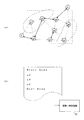
なお、経路データの保存態様は任意であるが、経路に含まれるノード列を記憶することが簡便である。図7(a)に示すように、スタートノード、ノードq2、ノードq3、ノードq6、ゴールノードの順で経路が形成されたとき、図7(b)に示すように、その順番に並べられたノード名を記憶すればよい。 In addition, although the preservation | save mode of route data is arbitrary, it is easy to memorize | store the node row | line | column contained in a route. As shown in FIG. 7A, when the route is formed in the order of the start node, the node q2, the node q3, the node q6, and the goal node, they are arranged in that order as shown in FIG. 7B. What is necessary is just to memorize | store a node name.
次に、移動コストを増加する(S210)。具体的には、経路修正部40は、干渉ノードに接続されたエッジに付与されたコストの増加をロードマップ一時記憶部22に対して指示する。これを受けて、ロードマップ一時記憶部22は、その指示により特定されたエッジのコストを増加する。これによって、今回探索された経路以外の他の経路が探索される可能性が高められる。
Next, the movement cost is increased (S210). Specifically, the
例えば、図8に示すように、ノードq3が干渉ノードのとき、ノードq2とノードq3間のエッジのコストを増加させる。具体的には、ノードq3とノードq2間のエッジに付与されたコストを倍増する。図8(a)と図8(b)の対比から明らかなように、ノードq2とノードq3間のエッジに付与されたコストが70から140になっている。このように干渉ノードに至るエッジのコストを増加することによって、当該干渉ノードが経路に含まれない確率を高めることができ、他の代替経路が探索される可能性を高めることができる。 For example, as shown in FIG. 8, when the node q3 is an interference node, the cost of the edge between the nodes q2 and q3 is increased. Specifically, the cost given to the edge between the nodes q3 and q2 is doubled. As is clear from the comparison between FIG. 8A and FIG. 8B, the cost given to the edge between the node q2 and the node q3 is 70 to 140. Thus, by increasing the cost of the edge reaching the interference node, it is possible to increase the probability that the interference node is not included in the route, and to increase the possibility of searching for another alternative route.
保存経路がある場合(S201)、今回探索された経路と前回の経路とを比較し、両者が一致しているか否かを判断する(S202)。具体的には、経路比較部64には、経路一時記憶部62に記憶された前回探索された経路と、今回探索された経路とを比較する。なお、経路の一致性の具体的な判断手法は任意である。例えば、経路に含まれるノード総数及びノード順番に基づいて経路の一致性は判断される。今回探索された経路は、経路修正部40から経路比較部64へ供給され、前回探索された経路は、経路一時記憶部62から経路比較部64へ供給される。
When there is a saved route (S201), the route searched this time is compared with the previous route, and it is determined whether or not they match (S202). Specifically, the
比較対象とした経路が一致していないとき、今回探索された経路を一時保存する(S209)。具体的には、経路修正部40は、今回探索された経路を経路一時記憶部62に記憶する。これによって、経路一時記憶部62には、最新の経路が記憶されることになる。なお、経路修正部40は、経路比較部64から供給される不一致信号に応じて、経路一時記憶部62に対して経路データの更新を指示する。
When the routes to be compared do not match, the route searched this time is temporarily saved (S209). Specifically, the
比較対象の経路が一致しているとき、追加ノードを生成する(S203)。具体的には、経路比較部64は、一致判定された経路データを追加ノード生成部70に対して供給し、追加ノード生成部70は、干渉と判定されたノードの周囲に所定数の追加ノードを追加する。なお、追加ノード生成部70により追加される追加ノード数は任意であり、複数に限らず、単数であっても良い。なお、追加ノードの生成数を所定数に限定することによって、計算コストの極端な増加を回避することができる。
When the comparison target paths match, an additional node is generated (S203). Specifically, the
追加ノードの生成方法は任意である。例えば、式(2)により規定される追加ノードは、干渉ノードの構成値を式(2)に代入することによって算出される。干渉ノードがqc=(qc1,qc2,・・・,qcN)で表現されるものとする。qc1を式(3)に代入することで、qi1が算出される。qc2を式(3)に代入することで、qi2が算出される。これをqcNまで繰り返すことでqiNが算出され、追加ノードの値が定まる。なお、式(3)に含まれる関数rand()は、−1<rand()<1の条件を満足する値をランダムに出力する関数である。
qi=(qi1,qi2,・・・,qiN) ・・・式(2)
qij=qcj(1+σ×rand()) ・・・式(3)
The method for generating the additional node is arbitrary. For example, the additional node defined by Expression (2) is calculated by substituting the configuration value of the interference node into Expression (2). Assume that the interference node is represented by q c = (q c1 , q c2 ,..., Q cN ). By substituting q c1 into equation (3), q i1 is calculated. q i2 is calculated by substituting q c2 into equation (3). By repeating this up to q cN , q iN is calculated, and the value of the additional node is determined. The function rand () included in Expression (3) is a function that randomly outputs a value that satisfies the condition of −1 <rand () <1.
q i = (q i1 , q i2 ,..., q iN ) (2)
q ij = q cj (1 + σ × rand ()) (3)
ステップS200〜202を経てステップ203に至る場合は、干渉ノードが連続しない態様にて経路上に存在し、かつ、干渉ノードに至るエッジに付与されたコストを増加しても代替的な経路が探索されない場合である。このような場合、干渉ノードの位置を適切に修正して当該ノードを非干渉状態とすることで経路全体が有効化できる可能性がある。本実施形態では、この点に鑑みて、干渉ノードの周囲に追加ノードを配置し、この追加ノードの干渉性を判断し、干渉ノードを非干渉の追加ノードで置き換える。これによって、干渉ノードを経路中に含まない非干渉経路の算出確率を効果的に高めることができる。 In the case of reaching step 203 via steps S200 to 202, an alternative route is searched even if the interference node exists on the route in a non-continuous manner and the cost given to the edge leading to the interference node is increased. If not. In such a case, there is a possibility that the entire route can be validated by appropriately correcting the position of the interference node to make the node in a non-interference state. In the present embodiment, in view of this point, an additional node is arranged around the interference node, the coherence of the additional node is determined, and the interference node is replaced with a non-interference additional node. Thereby, it is possible to effectively increase the calculation probability of a non-interference route that does not include an interference node in the route.
追加ノード生成後、非干渉の追加ノードの有無を判断する(S204)。具体的には、干渉判定部42は、追加ノード生成部70により生成された追加ノードが、環境情報取得部30から供給されるデータから検知される障害物に対して干渉するか否かを判定する。
After the additional node is generated, the presence / absence of a non-interfering additional node is determined (S204). Specifically, the
例えば、図9に示す場合、追加ノード生成部70は、ノードq3の周囲に追加ノードqn1〜qnNを生成する。干渉判定部42は、ノードqn1から干渉性を順に判定し、ノードqn5が非干渉ノードであることを検知する。なお、図9(a)は、ノードq3の周囲に追加ノードが生成されたことを模式的に示し、図9(b)は、ノードq3の周囲のqn5以外は干渉ノードであることを模式的に示す。
For example, in the case illustrated in FIG. 9, the additional
非干渉の追加ノードがない場合は、追加ノードの生成をもってしても障害物回避できない場合に相当する。この場合、追加ノードの生成対象となった干渉ノード及びこれに対して接続されたエッジを削除する(ステップS211)。ノード及びエッジの削除は、経路修正部40により指示され、ロードマップ一時記憶部22により実行される。その後、ステップS101へ帰還する。
When there is no non-interfering additional node, this corresponds to a case where obstacle avoidance is not possible even with the generation of the additional node. In this case, the interference node that is the generation target of the additional node and the edge connected thereto are deleted (step S211). The deletion of nodes and edges is instructed by the
非干渉追加ノードがある場合、置換処理を実行する(S205)。具体的には、図10に模式的に示すように、経路修正部40は、追加ノードの生成対象となった干渉ノードを非干渉の追加ノードへ置き換える。まず、ノード置換実行部44は、図10(a)に示すように、干渉ノードq3及びこれに接続されたエッジを削除する。次に、ノード置換実行部44は、図10(b)に示すように、追加ノードqn5に対してエッジを生成する。具体的には、ノードq2と追加ノードqn5をエッジにより接続し、追加ノードqn5とノードq6間をエッジにより接続する。このようにして、ノードq3が追加ノードqn5に置き換えられる。経路修正部40は、修正後の経路を軌道補間部50へ供給する。
If there is a non-interference added node, a replacement process is executed (S205). Specifically, as schematically illustrated in FIG. 10, the
次に、補間処理する(S206)。具体的には、軌道補間部50は、経路修正部40から供給された経路に対して所定間隔Δqで離散点を設ける(図11(a)参照)。
Next, interpolation processing is performed (S206). Specifically, the
次に、最終確認をする(S207)。具体的には、干渉判定部42は、軌道補間部50から供給された経路上のノード及び離散点が障害物と干渉しているか否かを判定する(図11(b)参照)。離散点が障害物と干渉しているかを判定することによって、ロボットアームが障害物と接触することをより確実に回避することができる。また、経路修正部40は、ロボットアームが許容する条件(例えば、ロボットアームの関節の可動角度)を満足するか否かを判定する。ロボットアームの関節の可動角度以外の場合、ロボットアームは、その経路に沿って動き得ないため、このような無意味な経路を排除する。
Next, a final confirmation is made (S207). Specifically, the
最終確認NGの場合、干渉ノードが置き換えられた非干渉の追加ノードを削除する(S208)。具体的には、経路修正部40は、ノード置換実行部44により導入された追加ノードを削除する。次に、S204へ移行し、その余の追加ノードに非干渉の追加ノードが存在するか判定される。その後の処理は、上述の説明と同様である。
In the case of final confirmation NG, the non-interfering additional node in which the interfering node is replaced is deleted (S208). Specifically, the
上述の説明から明らかなように、本実施形態では、ノードが連続して干渉しているか否かを判断基準として経路を選別する。ノードが連続して干渉している場合、干渉ノードの位置を調整したとしても障害物を回避できる可能性は高くないと推定できる。従って、この場合、干渉ノード自体をロードマップから削除し、他の代替的なルートを探索することを可能とする。これにより、相対的な短い時間で経路探索することが可能になる場合が見込まれる。 As is clear from the above description, in this embodiment, the route is selected based on whether or not the node continuously interferes. When nodes are continuously interfering, it can be estimated that the possibility of avoiding an obstacle is not high even if the position of the interfering node is adjusted. Therefore, in this case, it is possible to delete the interference node itself from the road map and search for another alternative route. As a result, it may be possible to search for a route in a relatively short time.
更に、本実施形態では、連続して探索される経路の一致性を判断し、一致しているときに初めて追加ノードに基づく経路修正ステップ(端的には、S203)へ移行する。連続して探索される経路が一致しない場合には、エッジに付与されたコストの値を調整し、再度の経路探索を実行することで、他の経路が探索されることが見込まれる。これにより、相対的な短い時間で代替的な経路を探索することが可能になる場合が見込まれる。 Furthermore, in this embodiment, the consistency of the route searched continuously is determined, and when there is a match, the process proceeds to the route correction step based on the additional node (in short, S203). When the route searched continuously does not match, it is expected that another route will be searched by adjusting the value of the cost given to the edge and executing the route search again. As a result, it may be possible to search for an alternative route in a relatively short time.
また、本実施形態では、干渉ノードの構成値を所定関数に代入することにより追加ノードを算出する。これによって、複雑な計算を伴うことなく、追加ノードを算出することができる。追加ノード生成の対象となる干渉ノードの周囲に複数の追加ノードを輪状に生成することによって、障害物回避の可能性を高めることができる。なお、追加ノードの生成態様は任意である。例えば、対象となる干渉ノードを中心として球状に追加ノードを生成しても良い。追加ノードの生成数を所定数に限定することによって、計算コストの極端な増加も回避することかできる。 In the present embodiment, the additional node is calculated by substituting the configuration value of the interference node into a predetermined function. As a result, the additional node can be calculated without complicated calculation. The possibility of obstacle avoidance can be increased by generating a plurality of additional nodes in the form of a ring around an interference node that is a target for generating additional nodes. The generation mode of the additional node is arbitrary. For example, additional nodes may be generated in a spherical shape with the target interference node as the center. By limiting the number of additional nodes generated to a predetermined number, it is possible to avoid an extreme increase in calculation cost.
実施の形態2
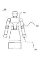
図12乃至図14を参照して実施の形態2について説明する。図12は、ロボットの模式図である。図13は、ロボットの概略的な構成を示すブロック図である。図14は、ロボットの動作を説明するための説明図である。
The second embodiment will be described with reference to FIGS. FIG. 12 is a schematic diagram of a robot. FIG. 13 is a block diagram illustrating a schematic configuration of the robot. FIG. 14 is an explanatory diagram for explaining the operation of the robot.
実施の形態1に示した軌道計画装置100は、例えば、図12に示すロボット300に内蔵される。図12に示すロボット300は、頭部及び車輪部が設けられた胴部301、胴部301に対して設けられたアーム部302、およびアーム部302の先端に設けられたハンド部303を有する。アーム部302の関節には電気モーター等の駆動部が設けられており、アーム部302は関節運動可能に構成されている。なお、アーム部302の運動は、胴部301に内蔵するコンピュータにより制御される。
The
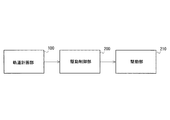
図12に示すロボット300は、図13に示すシステム構成を含む。図13に示すように、図1に示した軌道計測装置100に対応する軌道計画部100の出力は、駆動制御部200へ供給され、駆動制御部200の出力は、駆動部210へ供給される。
A
駆動制御部200は、軌道計画部10から供給される経路データに応じて、駆動部210を制御する。図11に示した経路データが供給されると、駆動制御部200は、順次、離散点/ノードにより指定される姿勢となるように駆動部210を制御する。駆動部210は、駆動制御部200により制御され、これにより、ロボット300のアーム部302の運動が実現される。図14に模式的に示すように、ロボット300のハンド部303は、経路上の進行し、ノードqn5、q6を介して、把持対象物を把持することができるゴールノードにより指定される位置まで移動する。本実施形態でも、実施の形態1で説明したものと同様の効果を得ることができる。
The
なお、本発明は上記実施の形態に限られたものではなく、趣旨を逸脱しない範囲で適宜変更することが可能である。ノードにより指定される対象は、3次元的な姿勢に限られるべきではなく、2次元空間上の位置であっても良い。ロボット以外の様々な機械/装置に適用し得る。 Note that the present invention is not limited to the above-described embodiment, and can be changed as appropriate without departing from the spirit of the present invention. The target specified by the node should not be limited to a three-dimensional posture, but may be a position in a two-dimensional space. It can be applied to various machines / devices other than robots.
100 軌道計画装置
10 ロードマップ記憶部
20 経路供給部
22 ロードマップ一時記憶部
24 接続ノード探索部
26 経路探索部
30 環境情報取得部
40 経路修正部
42 干渉判定部
44 ノード置換実行部
50 軌道補間部
60 経路一致判定部
62 経路一時記憶部
64 経路比較部
70 追加ノード生成部
80 計算機部分
200 駆動制御部
210 駆動部
300 ロボット
301 胴部
302 アーム部
303 ハンド部
100 trajectory planning device
10 road
200
300
Claims (14)
環境情報に基づいて前記経路情報に含まれる前記ノードの干渉性を判定する干渉判定部と、
前記干渉判定部により干渉有りと判定された前記ノードの周囲に追加ノードを生成する追加ノード生成部と、
前記干渉判定部による前記追加ノードの干渉性の判定結果に応じて、干渉有りと判定された前記ノードを前記追加ノードに置き換えるノード置換実行部と、
を備える、経路情報修正装置。 A route information correction device for correcting route information configured by connection between nodes via an edge,
An interference determination unit that determines the coherence of the node included in the route information based on environment information;
An additional node generation unit that generates an additional node around the node determined to have interference by the interference determination unit;
A node replacement execution unit that replaces the node determined to have interference with the additional node in accordance with the determination result of the coherency of the additional node by the interference determination unit;
A route information correction apparatus comprising:
前記追加ノード生成部は、連続しない態様にて干渉している前記ノードの周囲に前記追加ノードを生成することを特徴とする請求項1に記載の経路情報修正装置。 The interference determination unit determines whether or not a node adjacent to the node determined to have the interference via an edge is also determined to have interference,
The route information correction apparatus according to claim 1, wherein the additional node generation unit generates the additional node around the nodes that interfere with each other in a discontinuous manner.
当該経路情報修正装置は、前記干渉判定部により、前記干渉有りと判定された前記ノードにエッジを介して隣接するノードも干渉有りと判定された場合、連続的に干渉している各ノード及び当該ノードらに接続されたエッジの削除を指示する。 The path information correction device according to claim 1, wherein the interference determination unit determines whether or not a node adjacent to the node determined to have the interference via an edge is also determined to have interference. And
When the interference determination unit determines that a node adjacent to the node determined to have interference through an edge is also determined to have interference by the interference determination unit, the path information correction device Instructs the nodes to delete the connected edge.
当該経路情報修正装置は、前記干渉判定部により連続しない態様にて干渉していると判定された前記ノードに至るエッジのコストの増加を指示する。 The route according to any one of claims 1 to 3, wherein the interference determination unit determines whether or not a node adjacent to the node determined to have the interference via an edge is also determined to have interference. An information correction device,
The route information correction apparatus instructs the cost of an edge reaching the node determined to be interfering in a non-continuous manner by the interference determination unit.
前記追加ノード生成部は、前記比較判定部によって時間的に連続して探索された前記経路情報同士が一致すると判定されたとき、前記干渉判定部により干渉有りと判定された前記ノードに基づいて前記追加ノードを生成することを特徴とする請求項1乃至4のいずれか一項に記載の経路情報修正装置。 A comparison / determination unit that determines the match between the route information;
The additional node generation unit, based on the node determined to have interference by the interference determination unit when it is determined that the path information searched continuously in time by the comparison determination unit match. The route information correction apparatus according to claim 1, wherein an additional node is generated.
前記追加ノード生成部は、前記比較判定部によって時間的に連続して探索された前記経路情報同士が一致すると判定されたとき、前記干渉判定部により干渉有りと判定された前記ノードに基づいて前記追加ノードを生成する請求項1乃至5のいずれか一項に記載の経路情報修正装置であって、
前記追加ノード生成部は、所定数の前記追加ノードを生成し、
前記干渉判定部は、所定数の前記追加ノードに含まれる前記追加ノードの干渉性を順に判定する。 A comparison / determination unit that determines the match between the route information;
The additional node generation unit, based on the node determined to have interference by the interference determination unit when it is determined that the path information searched continuously in time by the comparison determination unit match. The route information correction device according to any one of claims 1 to 5, wherein the route information correction device generates an additional node.
The additional node generation unit generates a predetermined number of the additional nodes,
The interference determination unit sequentially determines the coherence of the additional nodes included in a predetermined number of the additional nodes.
前記補間処理部は、前記経路情報に含まれる経路に対して所定間隔で離散点を設け、
前記干渉判定部は、前記環境情報に基づいて前記離散点の干渉性を判定することを特徴とする請求項1乃至8のいずれか一項に記載の経路情報修正装置。 An interpolation processing unit for executing a route interpolation process on the route information processed by the node replacement execution unit;
The interpolation processing unit provides discrete points at predetermined intervals with respect to a route included in the route information,
The path information correction apparatus according to claim 1, wherein the interference determination unit determines the coherence of the discrete points based on the environment information.
前記ロードマップ情報から得られるコスト情報の処理に基づいて、スタート及びゴールノード間の経路を探索する経路探索部と、
前記経路探索部から供給される前記経路情報を修正する請求項1乃至9のいずれか一項に記載の経路情報修正装置と、
を備える軌道計画装置。 A roadmap storage unit that stores roadmap information in which a plurality of nodes are connected via cost-set edges;
A route search unit that searches for a route between the start and goal nodes based on the processing of the cost information obtained from the road map information;
The route information correction device according to any one of claims 1 to 9, wherein the route information supplied from the route search unit is corrected.
A trajectory planning device.
環境情報に基づいて前記経路情報に含まれる前記ノードの干渉性を判定し、
前記判定により干渉有りと判定された前記ノードの周囲に追加ノードを生成し、
前記判定による前記追加ノードの干渉性の判定結果に応じて、干渉有りと判定された前記ノードを前記追加ノードに置き換える、経路情報修正装置の動作方法。 An operation method of a route information correction device for correcting route information configured by connection between nodes via an edge,
Determining the coherence of the node included in the route information based on environmental information;
An additional node is generated around the node determined to have interference by the determination,
An operation method of a path information correction apparatus, wherein the node determined to be in interference is replaced with the additional node according to the determination result of the coherence of the additional node by the determination.
Priority Applications (1)
| Application Number | Priority Date | Filing Date | Title |
|---|---|---|---|
| JP2011055483A JP2012190405A (en) | 2011-03-14 | 2011-03-14 | Route information correcting device, track planning device, and robot |
Applications Claiming Priority (1)
| Application Number | Priority Date | Filing Date | Title |
|---|---|---|---|
| JP2011055483A JP2012190405A (en) | 2011-03-14 | 2011-03-14 | Route information correcting device, track planning device, and robot |
Publications (1)
| Publication Number | Publication Date |
|---|---|
| JP2012190405A true JP2012190405A (en) | 2012-10-04 |
Family
ID=47083450
Family Applications (1)
| Application Number | Title | Priority Date | Filing Date |
|---|---|---|---|
| JP2011055483A Withdrawn JP2012190405A (en) | 2011-03-14 | 2011-03-14 | Route information correcting device, track planning device, and robot |
Country Status (1)
| Country | Link |
|---|---|
| JP (1) | JP2012190405A (en) |
Cited By (22)
| Publication number | Priority date | Publication date | Assignee | Title |
|---|---|---|---|---|
| JP2014211760A (en) * | 2013-04-18 | 2014-11-13 | 株式会社豊田中央研究所 | Route modification device |
| WO2015182208A1 (en) * | 2014-05-26 | 2015-12-03 | 日立建機株式会社 | Traffic control server |
| JP2017045250A (en) * | 2015-08-26 | 2017-03-02 | トヨタ自動車株式会社 | Omnidirectional mobile body, control method thereof and program |
| KR101748632B1 (en) * | 2015-10-29 | 2017-06-20 | 한국과학기술연구원 | Robot control system and method for planning driving path of robot |
| CN107206592A (en) * | 2015-01-26 | 2017-09-26 | 杜克大学 | Special purpose robot's motion planning hardware and production and preparation method thereof |
| WO2017214581A1 (en) | 2016-06-10 | 2017-12-14 | Duke University | Motion planning for autonomous vehicles and reconfigurable motion planning processors |
| JP2020009405A (en) * | 2018-07-03 | 2020-01-16 | パナソニックIpマネジメント株式会社 | Design support system, design support method, and program |
| JP2020008962A (en) * | 2018-07-03 | 2020-01-16 | パナソニックIpマネジメント株式会社 | Movable body control system, movable body system, movable body control method, and program |
| CN110737262A (en) * | 2018-07-03 | 2020-01-31 | 松下知识产权经营株式会社 | Moving body control system, moving body control method, moving body system, and recording medium |
| WO2020116986A1 (en) * | 2018-12-07 | 2020-06-11 | 주식회사 유진로봇 | Autonomously traveling mobile robot and traveling control method therefor |
| JP2020132316A (en) * | 2019-02-14 | 2020-08-31 | 株式会社タダノ | Crane and route generation system |
| WO2020194253A1 (en) * | 2019-03-27 | 2020-10-01 | Rapyuta Robotics Co., Ltd. | Generating a 2d-navigation map for collision-free navigation by multiple robots |
| US10921143B2 (en) | 2017-06-20 | 2021-02-16 | Kabushiki Kaisha Toshiba | Information processing device, mobile object, information processing method, and computer program product |
| JP2021516630A (en) * | 2018-03-21 | 2021-07-08 | 北京猟戸星空科技有限公司Beijing Orion Star Technology Co.,Ltd. | Robot motion sequence generation method and device |
| CN113269728A (en) * | 2021-05-08 | 2021-08-17 | 深圳市鹏创达自动化有限公司 | Visual edge-tracking method, device, readable storage medium and program product |
| US11235465B2 (en) | 2018-02-06 | 2022-02-01 | Realtime Robotics, Inc. | Motion planning of a robot storing a discretized environment on one or more processors and improved operation of same |
| US11292456B2 (en) | 2018-01-12 | 2022-04-05 | Duke University | Apparatus, method and article to facilitate motion planning of an autonomous vehicle in an environment having dynamic objects |
| KR20220128233A (en) * | 2021-03-12 | 2022-09-20 | 모셔널 에이디 엘엘씨 | Driving data guided spatial planning |
| US11623346B2 (en) | 2020-01-22 | 2023-04-11 | Realtime Robotics, Inc. | Configuration of robots in multi-robot operational environment |
| US11634126B2 (en) | 2019-06-03 | 2023-04-25 | Realtime Robotics, Inc. | Apparatus, methods and articles to facilitate motion planning in environments having dynamic obstacles |
| US11673265B2 (en) | 2019-08-23 | 2023-06-13 | Realtime Robotics, Inc. | Motion planning for robots to optimize velocity while maintaining limits on acceleration and jerk |
| US11738457B2 (en) | 2018-03-21 | 2023-08-29 | Realtime Robotics, Inc. | Motion planning of a robot for various environments and tasks and improved operation of same |
-
2011
- 2011-03-14 JP JP2011055483A patent/JP2012190405A/en not_active Withdrawn
Cited By (49)
| Publication number | Priority date | Publication date | Assignee | Title |
|---|---|---|---|---|
| JP2014211760A (en) * | 2013-04-18 | 2014-11-13 | 株式会社豊田中央研究所 | Route modification device |
| WO2015182208A1 (en) * | 2014-05-26 | 2015-12-03 | 日立建機株式会社 | Traffic control server |
| JP2015225394A (en) * | 2014-05-26 | 2015-12-14 | 日立建機株式会社 | Traffic management server |
| CN107206592A (en) * | 2015-01-26 | 2017-09-26 | 杜克大学 | Special purpose robot's motion planning hardware and production and preparation method thereof |
| US10723024B2 (en) | 2015-01-26 | 2020-07-28 | Duke University | Specialized robot motion planning hardware and methods of making and using same |
| JP2018505788A (en) * | 2015-01-26 | 2018-03-01 | デューク・ユニバーシティDuke University | Hardware for planning the operation of a dedicated robot, and its production and use |
| JP2017045250A (en) * | 2015-08-26 | 2017-03-02 | トヨタ自動車株式会社 | Omnidirectional mobile body, control method thereof and program |
| KR101748632B1 (en) * | 2015-10-29 | 2017-06-20 | 한국과학기술연구원 | Robot control system and method for planning driving path of robot |
| US10124488B2 (en) | 2015-10-29 | 2018-11-13 | Korea Institute Of Science And Technology | Robot control system and method for planning driving path of robot |
| JP7431273B2 (en) | 2016-06-10 | 2024-02-14 | デューク・ユニバーシティ | Motion planning and reconfigurable motion planning processor for autonomous vehicles |
| JP7181092B2 (en) | 2016-06-10 | 2022-11-30 | デューク・ユニバーシティ | Motion Planning and Reconfigurable Motion Planning Processor for Autonomous Vehicles |
| TWI758296B (en) * | 2016-06-10 | 2022-03-21 | 杜克大學 | System for motion planning for autonomous vehicles and related methods, motion planning device, and method of operating reconfigurable motion planning module |
| CN109477723A (en) * | 2016-06-10 | 2019-03-15 | 杜克大学 | Automatic driving vehicle motion planning and reconfigurable motion planning processor |
| US11429105B2 (en) | 2016-06-10 | 2022-08-30 | Duke University | Motion planning for autonomous vehicles and reconfigurable motion planning processors |
| JP2022084895A (en) * | 2016-06-10 | 2022-06-07 | デューク・ユニバーシティ | Operation planning and reconfigurable operation planning processor for autonomous vehicle |
| WO2017214581A1 (en) | 2016-06-10 | 2017-12-14 | Duke University | Motion planning for autonomous vehicles and reconfigurable motion planning processors |
| EP3449214B1 (en) * | 2016-06-10 | 2021-12-15 | Duke University | Motion planning for autonomous vehicles and reconfigurable motion planning processors |
| JP2019517702A (en) * | 2016-06-10 | 2019-06-24 | デューク・ユニバーシティDuke University | Operation Planning and Reconfigurable Operation Planning Processor for Autonomous Vehicles |
| CN109477723B (en) * | 2016-06-10 | 2023-02-21 | 杜克大学 | Autonomous vehicle motion planning and reconfigurable motion planning processor |
| US10921143B2 (en) | 2017-06-20 | 2021-02-16 | Kabushiki Kaisha Toshiba | Information processing device, mobile object, information processing method, and computer program product |
| US11970161B2 (en) | 2018-01-12 | 2024-04-30 | Duke University | Apparatus, method and article to facilitate motion planning of an autonomous vehicle in an environment having dynamic objects |
| US11292456B2 (en) | 2018-01-12 | 2022-04-05 | Duke University | Apparatus, method and article to facilitate motion planning of an autonomous vehicle in an environment having dynamic objects |
| US11745346B2 (en) | 2018-02-06 | 2023-09-05 | Realtime Robotics, Inc. | Motion planning of a robot storing a discretized environment on one or more processors and improved operation of same |
| US11235465B2 (en) | 2018-02-06 | 2022-02-01 | Realtime Robotics, Inc. | Motion planning of a robot storing a discretized environment on one or more processors and improved operation of same |
| JP7316294B2 (en) | 2018-03-21 | 2023-07-27 | 北京猟戸星空科技有限公司 | ROBOT MOTION SEQUENCE GENERATION METHOD AND APPARATUS, COMPUTER DEVICE AND STORAGE MEDIUM |
| JP2021516630A (en) * | 2018-03-21 | 2021-07-08 | 北京猟戸星空科技有限公司Beijing Orion Star Technology Co.,Ltd. | Robot motion sequence generation method and device |
| US11738457B2 (en) | 2018-03-21 | 2023-08-29 | Realtime Robotics, Inc. | Motion planning of a robot for various environments and tasks and improved operation of same |
| US11964393B2 (en) | 2018-03-21 | 2024-04-23 | Realtime Robotics, Inc. | Motion planning of a robot for various environments and tasks and improved operation of same |
| JP2020008962A (en) * | 2018-07-03 | 2020-01-16 | パナソニックIpマネジメント株式会社 | Movable body control system, movable body system, movable body control method, and program |
| JP7285441B2 (en) | 2018-07-03 | 2023-06-02 | パナソニックIpマネジメント株式会社 | Design support system, design support method and program |
| JP2020009405A (en) * | 2018-07-03 | 2020-01-16 | パナソニックIpマネジメント株式会社 | Design support system, design support method, and program |
| CN110737262A (en) * | 2018-07-03 | 2020-01-31 | 松下知识产权经营株式会社 | Moving body control system, moving body control method, moving body system, and recording medium |
| JP7149567B2 (en) | 2018-07-03 | 2022-10-07 | パナソニックIpマネジメント株式会社 | MOBILE BODY CONTROL SYSTEM, MOBILE BODY SYSTEM, MOBILE BODY CONTROL METHOD AND PROGRAM |
| WO2020116986A1 (en) * | 2018-12-07 | 2020-06-11 | 주식회사 유진로봇 | Autonomously traveling mobile robot and traveling control method therefor |
| JP2020132316A (en) * | 2019-02-14 | 2020-08-31 | 株式会社タダノ | Crane and route generation system |
| JP7223227B2 (en) | 2019-02-14 | 2023-02-16 | 株式会社タダノ | Crane and path generation system |
| JP7184309B2 (en) | 2019-03-27 | 2022-12-06 | Rapyuta Robotics株式会社 | Computer-implemented method, computer system, and computer-readable medium for generating a 2D navigation map for collision-free locomotion by multiple robots |
| US11054273B2 (en) | 2019-03-27 | 2021-07-06 | Rapyuta Robotics Co., Ltd. | Generating a 2D-navigation map for collision-free navigation by multiple robots |
| WO2020194253A1 (en) * | 2019-03-27 | 2020-10-01 | Rapyuta Robotics Co., Ltd. | Generating a 2d-navigation map for collision-free navigation by multiple robots |
| CN113728287B (en) * | 2019-03-27 | 2022-08-09 | 睿普育塔机器人株式会社 | Generating a 2D navigation map for collision-free navigation by multiple robots |
| CN113728287A (en) * | 2019-03-27 | 2021-11-30 | 睿普育塔机器人株式会社 | Generating a 2D navigation map for collision-free navigation by multiple robots |
| JP2021535504A (en) * | 2019-03-27 | 2021-12-16 | Rapyuta Robotics株式会社 | Computer-implemented methods, computer systems, and computer-readable media to generate 2D navigation maps for collision-free movement by multiple robots. |
| US11634126B2 (en) | 2019-06-03 | 2023-04-25 | Realtime Robotics, Inc. | Apparatus, methods and articles to facilitate motion planning in environments having dynamic obstacles |
| US11673265B2 (en) | 2019-08-23 | 2023-06-13 | Realtime Robotics, Inc. | Motion planning for robots to optimize velocity while maintaining limits on acceleration and jerk |
| US11623346B2 (en) | 2020-01-22 | 2023-04-11 | Realtime Robotics, Inc. | Configuration of robots in multi-robot operational environment |
| KR102601860B1 (en) * | 2021-03-12 | 2023-11-13 | 모셔널 에이디 엘엘씨 | Driving data guided spatial planning |
| US11946749B2 (en) | 2021-03-12 | 2024-04-02 | Motional Ad Llc | Driving data guided spatial planning |
| KR20220128233A (en) * | 2021-03-12 | 2022-09-20 | 모셔널 에이디 엘엘씨 | Driving data guided spatial planning |
| CN113269728A (en) * | 2021-05-08 | 2021-08-17 | 深圳市鹏创达自动化有限公司 | Visual edge-tracking method, device, readable storage medium and program product |
Similar Documents
| Publication | Publication Date | Title |
|---|---|---|
| JP2012190405A (en) | Route information correcting device, track planning device, and robot | |
| JP5998816B2 (en) | Route search method, route search device, robot control device, robot, and program | |
| JP5060619B2 (en) | Motion planning method, motion planning system, and recording medium | |
| TWI579669B (en) | Automatic obstacle avoidance method and control device for arm type robot | |
| US11292132B2 (en) | Robot path planning method with static and dynamic collision avoidance in an uncertain environment | |
| JP2006504192A (en) | Method and apparatus for forming a graph structure describing a surface having a free surface and an occupied surface, and a computer program and computer program product having program code means | |
| JP5659890B2 (en) | Robot trajectory planning system and trajectory planning method | |
| JP2006239844A (en) | Obstacle avoiding device, obstacle avoiding method, obstacle avoiding program and mobile robot device | |
| US10919154B2 (en) | Interference determination method, interference determination system, and computer program | |
| WO2021242215A1 (en) | A robot path planning method with static and dynamic collision avoidance in an uncertain environment | |
| JP2009053849A (en) | Path search system, path search method, and autonomous traveling body | |
| JP2012056023A (en) | Action generating system and method for robot | |
| JP4985163B2 (en) | Route search system, route search method, and autonomous mobile body | |
| JP2010061442A (en) | Autonomous mobile device | |
| JP4760732B2 (en) | Route creation device | |
| JP5061798B2 (en) | Movement path generation method, movement path generation apparatus, movement path generation program, robot arm control apparatus, and robot arm control program | |
| JP2018017654A (en) | Detector, robot, and robot controller | |
| US20210237270A1 (en) | Trajectory generation apparatus, multi-link system, and trajectory generation method | |
| US11992945B2 (en) | System and methods for training robot policies in the real world | |
| JP5766936B2 (en) | 3D environment restoration device, 3D environment restoration method, and robot | |
| CN117124335A (en) | Improved RRT path planning method based on path marking backtracking strategy | |
| JP5435729B2 (en) | Walking landing position planning method for legged robot | |
| JP5403086B2 (en) | Movement path generation method, movement path generation apparatus, movement path generation program, robot arm control apparatus, and robot arm control program | |
| JP7460356B2 (en) | Travel route generation device | |
| JP2012040635A (en) | System and method of trajectory planning of robot |
Legal Events
| Date | Code | Title | Description |
|---|---|---|---|
| A300 | Application deemed to be withdrawn because no request for examination was validly filed |
Free format text: JAPANESE INTERMEDIATE CODE: A300 Effective date: 20140603 |