JP2012189766A - Liquid crystal display device - Google Patents
Liquid crystal display device Download PDFInfo
- Publication number
- JP2012189766A JP2012189766A JP2011052650A JP2011052650A JP2012189766A JP 2012189766 A JP2012189766 A JP 2012189766A JP 2011052650 A JP2011052650 A JP 2011052650A JP 2011052650 A JP2011052650 A JP 2011052650A JP 2012189766 A JP2012189766 A JP 2012189766A
- Authority
- JP
- Japan
- Prior art keywords
- temperature
- liquid crystal
- display device
- crystal display
- temperature sensor
- Prior art date
- Legal status (The legal status is an assumption and is not a legal conclusion. Google has not performed a legal analysis and makes no representation as to the accuracy of the status listed.)
- Withdrawn
Links
Images


Classifications
-
- G—PHYSICS
- G02—OPTICS
- G02F—OPTICAL DEVICES OR ARRANGEMENTS FOR THE CONTROL OF LIGHT BY MODIFICATION OF THE OPTICAL PROPERTIES OF THE MEDIA OF THE ELEMENTS INVOLVED THEREIN; NON-LINEAR OPTICS; FREQUENCY-CHANGING OF LIGHT; OPTICAL LOGIC ELEMENTS; OPTICAL ANALOGUE/DIGITAL CONVERTERS
- G02F1/00—Devices or arrangements for the control of the intensity, colour, phase, polarisation or direction of light arriving from an independent light source, e.g. switching, gating or modulating; Non-linear optics
- G02F1/01—Devices or arrangements for the control of the intensity, colour, phase, polarisation or direction of light arriving from an independent light source, e.g. switching, gating or modulating; Non-linear optics for the control of the intensity, phase, polarisation or colour
- G02F1/13—Devices or arrangements for the control of the intensity, colour, phase, polarisation or direction of light arriving from an independent light source, e.g. switching, gating or modulating; Non-linear optics for the control of the intensity, phase, polarisation or colour based on liquid crystals, e.g. single liquid crystal display cells
- G02F1/133—Constructional arrangements; Operation of liquid crystal cells; Circuit arrangements
- G02F1/1333—Constructional arrangements; Manufacturing methods
- G02F1/133382—Heating or cooling of liquid crystal cells other than for activation, e.g. circuits or arrangements for temperature control, stabilisation or uniform distribution over the cell
-
- G—PHYSICS
- G02—OPTICS
- G02F—OPTICAL DEVICES OR ARRANGEMENTS FOR THE CONTROL OF LIGHT BY MODIFICATION OF THE OPTICAL PROPERTIES OF THE MEDIA OF THE ELEMENTS INVOLVED THEREIN; NON-LINEAR OPTICS; FREQUENCY-CHANGING OF LIGHT; OPTICAL LOGIC ELEMENTS; OPTICAL ANALOGUE/DIGITAL CONVERTERS
- G02F2203/00—Function characteristic
- G02F2203/21—Thermal instability, i.e. DC drift, of an optical modulator; Arrangements or methods for the reduction thereof
-
- G—PHYSICS
- G09—EDUCATION; CRYPTOGRAPHY; DISPLAY; ADVERTISING; SEALS
- G09G—ARRANGEMENTS OR CIRCUITS FOR CONTROL OF INDICATING DEVICES USING STATIC MEANS TO PRESENT VARIABLE INFORMATION
- G09G2320/00—Control of display operating conditions
- G09G2320/04—Maintaining the quality of display appearance
- G09G2320/041—Temperature compensation
Landscapes
- Physics & Mathematics (AREA)
- Nonlinear Science (AREA)
- Mathematical Physics (AREA)
- Chemical & Material Sciences (AREA)
- Crystallography & Structural Chemistry (AREA)
- General Physics & Mathematics (AREA)
- Optics & Photonics (AREA)
- Liquid Crystal (AREA)
- Liquid Crystal Display Device Control (AREA)
- Control Of Indicators Other Than Cathode Ray Tubes (AREA)
Abstract
Description
本発明は液晶パネルの温度情報を得るための温度センサが設けられた液晶表示装置に関する。 The present invention relates to a liquid crystal display device provided with a temperature sensor for obtaining temperature information of a liquid crystal panel.
下記特許文献1にあるように、従来、温度センサを用いて液晶パネルの温度を検知する液晶表示装置が提案されている。液晶パネルの温度情報は、例えば各画素の階調値の補正に利用される。 As disclosed in Patent Document 1 below, a liquid crystal display device that detects the temperature of a liquid crystal panel using a temperature sensor has been proposed. The temperature information of the liquid crystal panel is used, for example, for correcting the gradation value of each pixel.
液晶パネルの温度は液晶パネル上の位置によって異なる場合がある。例えば、光源を縁に有するバックライトユニットを備える液晶表示装置においては、液晶パネルの縁に近い部分(領域)の温度は、その他の領域に比べて高くなり易い。各領域の温度を検知することができれば、より精度の高い制御が可能となる。しかしながら、領域の数だけ温度センサを設けると、液晶表示装置のコストが増す。 The temperature of the liquid crystal panel may vary depending on the position on the liquid crystal panel. For example, in a liquid crystal display device including a backlight unit having a light source at the edge, the temperature of a portion (area) near the edge of the liquid crystal panel is likely to be higher than in other areas. If the temperature in each region can be detected, more accurate control is possible. However, providing as many temperature sensors as the number of regions increases the cost of the liquid crystal display device.
本発明の目的は、液晶パネルに規定された複数の領域のそれぞれの温度を少ない温度センサで得ることを可能とする液晶表示装置を提供することにある。 An object of the present invention is to provide a liquid crystal display device that can obtain the temperature of each of a plurality of regions defined in a liquid crystal panel with a small number of temperature sensors.
本発明に係る液晶表示装置は、少なくとも1つの温度センサと、前記少なくとも1つの温度センサよりも数の多い複数の領域が規定された液晶パネルと、前記少なくとも1つの温度センサの出力値と前記複数の領域のそれぞれの温度との関係を表す情報である温度関係情報が予め格納されたメモリと、前記少なくとも1つの温度センサの出力値を取得し、前記温度関係情報と前記取得した出力値とに基づいて前記複数の領域のそれぞれの温度を推定する制御装置とを備える。本発明によれば、複数の領域のそれぞれの温度を少ない温度センサで得ることが可能となる。 The liquid crystal display device according to the present invention includes at least one temperature sensor, a liquid crystal panel in which a plurality of regions more numerous than the at least one temperature sensor are defined, an output value of the at least one temperature sensor, and the plurality A memory in which temperature relationship information, which is information representing a relationship with each temperature in the region, is stored in advance, an output value of the at least one temperature sensor is acquired, and the temperature relationship information and the acquired output value are And a control device for estimating the temperature of each of the plurality of regions based on the control unit. According to the present invention, it is possible to obtain the temperature of each of a plurality of regions with a small number of temperature sensors.
本発明の一態様では、前記制御装置は、前記少なくとも1つの温度センサの出力値と前記複数の領域の温度との関係を表す、前記温度関係情報によって規定される複数の関係式を用いて、前記複数の領域のそれぞれの温度を推定してもよい。この態様によれば、各領域の温度として、連続的に変化する値を算出でき、温度の推定の精度を増すことができる。この態様では、前記メモリには、前記複数の領域にそれぞれ対応付けられた複数の係数が前記温度関係情報として格納されており、前記複数の関係式は前記複数の係数と当該複数の係数が選択的に適用可能な基礎関係式とにより規定されてもよい。この態様によれば、複数の領域にそれぞれ対応する複数の関係式を予めメモリに格納する必要がなくなる。例えば、1つの基礎関係式から、複数の領域にそれぞれ対応する複数の関係式を得ることができる。 In one aspect of the present invention, the control device uses a plurality of relational expressions defined by the temperature relation information that represents a relation between an output value of the at least one temperature sensor and a temperature of the plurality of regions. Each temperature of the plurality of regions may be estimated. According to this aspect, a continuously changing value can be calculated as the temperature of each region, and the accuracy of temperature estimation can be increased. In this aspect, the memory stores a plurality of coefficients respectively associated with the plurality of regions as the temperature relation information, and the plurality of relational expressions are selected by the plurality of coefficients and the plurality of coefficients. May be defined by a basic relational expression that can be applied to the target. According to this aspect, it is not necessary to previously store a plurality of relational expressions respectively corresponding to a plurality of areas in the memory. For example, a plurality of relational expressions corresponding to a plurality of regions can be obtained from one basic relational expression.
また、本発明の他の態様では、前記制御装置は、前記液晶表示装置の駆動開始時からの経過時間に応じて変化する情報に基づいて現時点が予め定められた定常期間に該当するか否かを判定し、前記制御装置は、現時点が前記定常期間に該当する場合と現時点が前記定常期間に該当しない場合とでは、前記複数の領域の温度を推定するための処理として異なる処理を実行してもよい。この態様によれば、現時点が定常期間でない場合でも、適切に液晶パネルの温度を推定できる。この態様では、前記液晶表示装置には、前記少なくとも1つの温度センサとして、互いに離れて配置される2つの温度センサが設けられ、前記制御装置は、前記液晶表示装置の駆動開始時からの経過時間に応じて変化する前記情報として、前記2つの温度センサの出力値の差を用いてもよい。この態様によれば、現時点が定常期間に該当するか否かを容易に判断できる。 In another aspect of the present invention, the control device determines whether or not the current time corresponds to a predetermined steady period based on information that changes according to an elapsed time from the start of driving of the liquid crystal display device. The control device executes different processes as processes for estimating the temperatures of the plurality of regions when the current time corresponds to the steady period and when the current time does not correspond to the steady period. Also good. According to this aspect, the temperature of the liquid crystal panel can be appropriately estimated even when the current time is not a steady period. In this aspect, the liquid crystal display device is provided with two temperature sensors that are arranged apart from each other as the at least one temperature sensor, and the control device has elapsed time from the start of driving of the liquid crystal display device. A difference between output values of the two temperature sensors may be used as the information that changes according to the above. According to this aspect, it can be easily determined whether or not the current time corresponds to a steady period.
また、本発明のさらに他の態様では、前記液晶表示装置は、導光板と前記導光板の少なくとも一辺に配置された光源とを有するバックライトユニットをさらに備えてもよい。この態様によれば、複数の領域のそれぞれについて温度を推定する処理が特に有効に作用する。また、この態様では、前記液晶表示装置は、前記少なくとも1つの温度センサが取り付けられ前記導光板の前記少なくとも一辺に沿って配置される回路基板をさらに備えてもよい。こうすることにより、温度センサの出力値と液晶パネルの温度との相関を増すことができる。さらに、前記液晶表示装置は、前記バックライトユニットの背面を覆う金属製の後フレームを備え、前記回路基板は前記後フレームに固定されてもよい。これによれば、温度センサの出力値と液晶パネルの温度との相関をさらに増すことができる。また、前記液晶表示装置は、複数の回路基板をさらに備え、前記少なくとも1つの温度センサは前記複数の回路基板のうち最も光源に近い回路基板に取り付けられてもよい。これによれば、温度センサの出力値と液晶パネルの温度との相関をさらに増すことができる。また、この態様では、前記光源は複数のLEDを含んでもよい。このようにLEDを用いる場合には、複数の領域のそれぞれについて温度を推定する処理が特に有効に作用する。 In yet another aspect of the present invention, the liquid crystal display device may further include a backlight unit having a light guide plate and a light source disposed on at least one side of the light guide plate. According to this aspect, the process of estimating the temperature for each of the plurality of regions works particularly effectively. In this aspect, the liquid crystal display device may further include a circuit board to which the at least one temperature sensor is attached and arranged along the at least one side of the light guide plate. By doing so, the correlation between the output value of the temperature sensor and the temperature of the liquid crystal panel can be increased. Furthermore, the liquid crystal display device may include a metal rear frame that covers a back surface of the backlight unit, and the circuit board may be fixed to the rear frame. According to this, the correlation between the output value of the temperature sensor and the temperature of the liquid crystal panel can be further increased. The liquid crystal display device may further include a plurality of circuit boards, and the at least one temperature sensor may be attached to a circuit board closest to the light source among the plurality of circuit boards. According to this, the correlation between the output value of the temperature sensor and the temperature of the liquid crystal panel can be further increased. In this aspect, the light source may include a plurality of LEDs. Thus, when using LED, the process which estimates temperature about each of several area | region acts especially effectively.
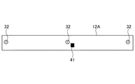
以下、本発明の一実施形態について図面を参照しながら説明する。図1は本発明の実施形態の例である液晶表示装置1の断面図である。図2は液晶表示装置1が備える液晶パネル10やバックライトユニット20の背面を覆う後フレーム31の背面の概略図である。
Hereinafter, an embodiment of the present invention will be described with reference to the drawings. FIG. 1 is a cross-sectional view of a liquid crystal display device 1 which is an example of an embodiment of the present invention. FIG. 2 is a schematic view of the back surface of the
液晶表示装置1は例えばテレビジョンとして機能する装置である。図1に示すように、液晶表示装置1は液晶パネル10を有している。液晶パネル10は互いに対向する2つの透明基板を有している。一方の基板(TFT基板)10aには、複数のTFT(Thin Film Transistor)が形成されている。TFT基板10aには、複数の走査線と複数の信号線とが格子状に形成されている。走査線にはTFTをオン/オフするゲート電圧が印加される。信号線には各画素の階調値を表す画像信号が印加される。他方の基板(カラーフィルタ基板)10bにはカラーフィルタが形成されている。TFT基板10aとカラーフィルタ基板10bとの間には液晶10cが封入されている。
The liquid crystal display device 1 is a device that functions as a television, for example. As shown in FIG. 1, the liquid crystal display device 1 has a
図1に示すように、液晶表示装置1は、液晶パネル10の背面側に配置され液晶パネル10の背面に光を照射するバックライトユニット20を有している。この例のバックライトユニット20はその縁に光源を有している。バックライトユニット20は光源として複数のLED(Light Emitting Diode)21を有している。この例では、複数のLED21はバックライトユニット20の下縁と上縁とに沿って配置されている。詳細には、バックライトユニット20は導光板22と導光板22の下辺に沿って配置される回路基板21aと導光板22の上辺に沿って配置される回路基板(不図示)とを有している。LED21は回路基板21aに実装され、導光板22の下面に対向している。導光板22の背面には反射板23が配置されている。導光板22に向けて射出されたLED21の光は、導光板22内を進みながら反射板23で前方に向けて反射され、液晶パネル10の背面に照射される。導光板22の前面には複数の光学シート25が配置されている。なお、バックライトユニット20の光源はLEDに限られない。例えば、光源として冷陰極管が設けられてもよい。また、光源は、導光板22の下辺又は上辺のいずれか一方にのみ配置されてもよい。
As shown in FIG. 1, the liquid crystal display device 1 includes a
図1に示すように、液晶表示装置1は金属製の放熱板24を有している。放熱板24はバックライトユニット20の縁に沿って配置され、LED21からの熱を吸収し、LED21の近傍に熱が集中するのを防ぐ。この例の放熱板24は回路基板21aの下面に固定される下板部24aと、下板部24aの縁で屈曲しバックライトユニット20の背面(詳細には導光板22の背面)と対向する後板部24bとを有している。下板部24aと後板部24bは一体的に形成されている。放熱板24はバックライトユニット20の左右方向(図2においてX1−X2で示す方向)の幅と概ね同じ長さを有している。この放熱板24により後述する温度センサ41にLED21の熱が伝わりやすくなっている。
As shown in FIG. 1, the liquid crystal display device 1 has a
図1に示すように、液晶表示装置1はさらに金属製の後フレーム31を有している。後フレーム31は板状であり、バックライトユニット20の背面を覆っている。この例の後フレーム31はバックライトユニット20の背面(詳細には導光板22の背面)と対向する後板部31bと後板部31bの縁に形成される下板部31aとを有している。下板部31aは回路基板21aの下面に沿って配置されている。この例では、下板部31aと回路基板21aとの間に、上述した放熱板24の下板部24aが位置している。また、後板部31bの最下部と導光板22との間に、放熱板24の後板部24bが位置している。そのため、LED21の熱が放熱板24を介して後フレーム31の最下部に伝わりやすくなっている。
As shown in FIG. 1, the liquid crystal display device 1 further includes a metal
図1及び図2に示すように、後フレーム31には回路基板12A,12Bが固定されている。回路基板12A,12Bは後フレーム31の最下部に固定され、バックライトユニット20の下縁に沿って位置している。これにより、回路基板12A,12BにLED21の熱が伝わり易くなる。この例では、図1に示すように、回路基板12A,12Bとバックライトユニット20との間に放熱板24の後板部24bが位置している。これにより、回路基板12A,12BにLED21の熱がさらに伝わり易くなる。後板部24bは回路基板12A,12Bの上縁よりもさらに上方に伸びている。これにより、回路基板12A,12Bの広い範囲にLED21の熱が伝わり易くなる。
As shown in FIGS. 1 and 2, circuit boards 12 </ b> A and 12 </ b> B are fixed to the
液晶表示装置1は液晶パネル10の温度推定に利用される少なくとも1つの温度センサを備えている。この例の液晶表示装置1は、図1及び図2に示すように、1つの温度センサ41を備えている。温度センサ41は回路基板12Aに取り付けられている。
The liquid crystal display device 1 includes at least one temperature sensor used for temperature estimation of the
図2に示すように、液晶表示装置1はTFT制御基板13と、電源基板14と、アプリケーション基板15とをさらに有している。この例では、これらの基板13,14,15はいずれも後フレーム31に固定されている。また、この例では、後述する制御装置2やメモリ3はTFT制御基板13に実装されている。アプリケーション基板15には、例えば、外部機器に対するインターフェースとして機能する回路が実装されている。電源基板14には、液晶表示装置1が備える各回路にそれらの駆動電力を供給する電源回路が実装されている。
As shown in FIG. 2, the liquid crystal display device 1 further includes a
温度センサ41が取り付けられた回路基板12Aと、回路基板12Aと左右方向で並ぶ回路基板12Bは、液晶表示装置1が有する複数の回路基板のなかで最もLED21に近い回路基板である。この例では、TFT制御基板13は、後フレーム31の左右方向の中央部に位置し、回路基板12A,12Bの上方に位置している。電源基板14とアプリケーション基板15はTFT制御基板13の左右に配置され、それぞれ回路基板12A,12Bの上方に位置している。2つの回路基板12A,12Bのうち、回路基板12Aは電源基板14から離れて位置しているため、電源基板14からの熱の影響を受け難い。一方、回路基板12Bはアプリケーション基板15から離れて位置しているため、アプリケーション基板15からの熱の影響を受け難い。温度センサを一つだけ設ける場合には、これらの回路基板12A,12Bの中から温度をより適切に検出できる方を選択すればよい。本実施形態においては、電源基板14からの熱影響を考慮し、温度センサ41は回路基板12Aに配置されている。そのため、温度センサ41の出力値は電源基板14からの熱の影響を受け難い。
The circuit board 12 </ b> A to which the
温度センサ41の出力値に基づく後述する処理は、TFT基板13に実装された制御装置2において実行される。図2に示すように、TFT制御基板13には、回路基板12A,12Bとアプリケーション基板15とにFPC(Flexible printed circuits)16,17によって接続されている。上述したように、温度センサ41は回路基板12Aに取り付けられている。そのため、温度センサ41の出力信号を制御装置2に入力するための専用の配線を設ける必要がない。つまり、温度センサ41の出力信号は、FPC16を通して制御装置2に入力されている。
Processing to be described later based on the output value of the
上述したように、回路基板12AはLED21の熱が当該回路基板12Aに伝わりやすいように配置されている。そのため、温度センサ41の出力値にはLED21の熱が適切に反映される。液晶パネル10の温度はLED21の熱の影響を受けやすい。温度センサ41と回路基板12Aのこのような配置により、温度センサ41による液晶パネル10の温度推定の精度を増すことができる。
As described above, the
図1に示すように、液晶表示装置1は板状の基板カバー33を備えている。基板カバー33は回路基板12A,12Bを覆っている。温度センサ41は基板カバー33の内側に位置している。そのため、温度センサ41の出力値に外気温度が影響し難くい。その結果、温度センサ41を利用した液晶パネル10の温度推定の精度を増すことができる。この例の基板カバー33の縁は後フレーム31に向かって突出している。これにより、基板カバー33の内側に外気がさらに進入し難くい。
As shown in FIG. 1, the liquid crystal display device 1 includes a plate-
図1に示すように、回路基板12Aは螺子32によって後フレーム31に固定されている。図3は螺子32が取り付けられた状態の回路基板12Aの平面図である。同図において基板カバー33は省略されている。図3に示すように、回路基板12Aは複数の螺子32によって後フレーム31に固定されている。螺子32は金属製であり、後フレーム31の熱の一部は螺子32を通して回路基板12Aに伝えられる。温度センサ41の位置は1つの螺子32に近接している。そのため、温度センサ41の出力値にLED21からの熱がさらに適切に反映され得る。図1に示すように、この例の螺子32は基板カバー33の外側から差し込まれ、回路基板12Aだけでなく基板カバー33をも後フレーム31に固定している。温度センサ41は回路基板12Aと基板カバー33とによって挟まれている。
As shown in FIG. 1, the circuit board 12 </ b> A is fixed to the
図1に示すように、回路基板12A,12BはFPC12aを介して液晶パネル10の下縁に接続されている。FPC12aにはICチップ12bが実装されている。ICチップ12bは温度センサ41から離れて位置している。そのため、温度センサ41はICチップ12bからの熱を受け難くい。この例では、ICチップ12bは基板カバー33の外側に位置している。そのため、温度センサ41はICチップ12bから熱をさらに受け難くい。なお、ICチップ12bは後述する信号線駆動回路4として機能する。この回路基板12A,12Bは一般的にソース基板と称され、信号線駆動回路4と制御装置2とを結ぶ中継用の配線基板として機能する。ICチップ12bは、階調値に応じた電圧をTFTのソースに印加する。
As shown in FIG. 1, the
図1に示すように、液晶表示装置1は、液晶パネル10の外周部を覆う前カバー51と、後フレーム31の背面を覆い液晶表示装置1の背面を構成する後カバー52とを有している。さらに、液晶表示装置1は中間フレーム53を有している。
As shown in FIG. 1, the liquid crystal display device 1 includes a
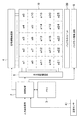
図4は液晶表示装置1が備える回路を概略的に示すブロック図である。同図に示すように、液晶表示装置1は、制御装置2と、メモリ3と、信号線駆動回路4と、走査線駆動回路5と、バックライト駆動回路6とを有している。
FIG. 4 is a block diagram schematically showing a circuit included in the liquid crystal display device 1. As shown in the figure, the liquid crystal display device 1 includes a
制御装置2には、不図示のチューナやアンテナで受信した入力画像信号や、映像再生装置など別の装置が生成した入力画像信号が入力される。制御装置2は、CPU(Central Processing Unit)を含み、ROM(Read Only Memory)やRAM(Randam Access Memoly)などのメモリ3に接続され、メモリ3に格納されたプログラムを実行する。例えば、制御装置2は入力画像信号に基づいて、各画素の階調値を示す出力画像信号を生成し、信号線駆動回路4に出力する。また、制御装置2は入力画像信号に基づいて、信号線駆動回路4及び走査線駆動回路5が同期を取るためのタイミング信号を生成し、各駆動回路に出力する。温度センサ41は制御装置2に接続されている。本実施形態の制御装置2は、温度センサ41の出力値に基づいて、液晶パネル10の温度を推定する処理を実行する。制御装置2が実行する処理については後において詳説する。
An input image signal received by a tuner or an antenna (not shown) or an input image signal generated by another device such as a video playback device is input to the
走査線駆動回路5はTFT基板10aに形成された走査線に接続され、制御装置2から入力されるタイミング信号に合わせて複数の走査線に順番にゲート電圧を印加する。走査線駆動回路5は、例えば液晶パネル10の左右に配置される、不図示の基板に実装される。
The scanning line driving circuit 5 is connected to the scanning lines formed on the
信号線駆動回路4はTFT基板10aに形成された信号線に接続され、ゲート電圧の印加タイミングに合わせて、制御装置2からの出力画像信号に応じた電圧を信号線に印加する。信号線駆動回路4は、本実施形態では、FPC12aに実装されるが、例えば回路基板12A,12BまたはTFT基板10aに実装されてもよい。
The signal
バックライト駆動回路6は制御装置2から入力される信号に基づいて、LED21にその駆動電力を供給する。制御装置2はバックライトユニット20の制御モードとして、LED21の輝度が互いに異なる複数の制御モードを備えている。例えば、制御装置2は、LED21を高輝度で駆動する高輝度モードと、LED21を低輝度で駆動する低輝度モードと、LED21を中程度の輝度で駆動する中輝度モードとを備えている。バックライト駆動回路6は、制御装置2から制御モードを特定する信号を受けて、その制御モードに対応する駆動電力をLED21に供給する。バックライト駆動回路6も図示されない基板に実装されている。
The
図5は制御装置2の機能を示すブロック図である。同図に示すように、制御装置2はその機能として、センサ出力取得部2aと、温度推定部2bと、補正処理部2cとを備えている。
FIG. 5 is a block diagram illustrating functions of the
センサ出力取得部2aは予め設定されたサンプリング周期(例えば、10秒)で温度センサ41の出力値を取得する。温度センサ41からの出力がアナログの出力信号の場合は、不図示のA/D変換回路を通してデジタル信号として制御装置2に入力される。センサ出力取得部2aはデジタル信号が示す値を温度センサ41の出力値として取得する。一方、温度センサ41からの出力がデジタルの出力信号の場合は、センサ出力取得部2aはデジタル信号が示す値をそのまま温度センサ41の出力値として取得する。
The sensor
温度センサ41は上述したようにLED21からの熱の影響を受けやすい位置に取り付けられている。また、液晶パネル10の温度はLED21からの熱の影響を強く受ける。そのため、温度センサ41の出力値と液晶パネル10の温度とには相関がある。温度推定部2bはセンサ出力取得部2aで取得した出力値に基づいて液晶パネル10の温度を推定する。
As described above, the
本実施形態では、図4に示すように、温度センサ41よりも数の多い複数の領域a1〜a25が液晶パネル10上に規定されている。すなわち、液晶パネル10の全域が複数の領域a1〜a25に仮想的に区画されている。図4に示す例では、液晶パネル10は縦方向及び横方向のそれぞれにおいて5つに区画され、計25の領域を有している。なお、液晶パネル10に規定する領域の数はこれに限られず、液晶パネル10のサイズに応じて適宜変更されてよい。
In the present embodiment, as shown in FIG. 4, a plurality of regions a <b> 1 to a <b> 25 having a larger number than the
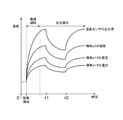
図6は温度センサ41の出力値の時間的な変化と各領域の実際の温度の時間的な変化の例を示す図である。同図では、領域a3,a13,a15の温度(実測値)が例として示されている。また、同図では、バックライトユニット20は、t1までは高輝度モードで駆動され、t1からt2までは低輝度モードで駆動され、t2以降は中輝度モードで駆動されている。同図に示すように、いずれの領域の温度も、バックライトユニット20の制御モードの切り換えに応じて変化している。液晶表示装置1では、バックライトユニット20の縁にLED21が配置されている。図6からは、液晶パネル10には各領域で温度分布が生じていることが分かる。温度センサ41は、図1に示されるように、LED21の温度を検出しやすい位置に配置されている。そのため、図6に示すように、温度センサ41の出力値と各領域の温度との間には相関がある。ここで説明する例では、液晶パネル10のLED21の配置位置(この例ではバックライトユニット20の上縁及び下縁)に近い領域の温度(同図では領域a3の温度)は、その他の領域(同図では領域a13及び領域a15)の温度よりも高くなっている。また、液晶パネル10の外周部における右側部分と左側部分の背面側では、基板などの熱源となる部品の数が少ない。そのため、液晶パネル10の右側部分や左側部分の温度(同図の例では領域a15の温度)は、パネル中央の領域の温度(同図では領域a13の温度)より低くなっている。このように、LED21の温度変化は、液晶パネル10の各領域の温度に対して支配的である。そのため、LEDの21の温度を受けやすい位置に置かれた温度センサ41の出力値から、領域a1〜a25の温度変化の傾向を捉えることができる。
FIG. 6 is a diagram illustrating an example of the temporal change of the output value of the
本実施形態では、メモリ3には、温度センサ41の出力値と各領域a1〜a25の温度との関係を表す情報である温度関係情報が予め格納されている。温度推定部2bは温度関係情報とセンサ出力取得部2aで取得した出力値とに基づいて複数の領域a1〜a25のそれぞれの温度を推定する。
In the present embodiment, the memory 3 stores in advance temperature relationship information that is information indicating the relationship between the output value of the
この例の温度推定部2bは、温度関係情報により規定される複数の関係式(以下、温度関係式)を用いて、領域a1〜a25のそれぞれの温度を推定する。複数の温度関係式は、温度センサ41の出力値と領域a1〜a25の温度との関係を表す。すなわち、複数の温度関係式は領域a1〜a25にそれぞれ対応しており、ある領域の温度と温度センサ41の出力値との関係は、当該領域に対応する温度関係式で表される。
The
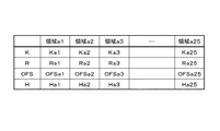
この例では、領域a1〜a25にそれぞれ対応付けられた複数の係数が、メモリ3に格納されている。ある領域についての温度関係式は、当該領域に対応する係数により規定される。また、この例では、領域a1〜a25にそれぞれ対応付けられた複数の係数が選択的に適用可能な基礎関係式がメモリ3に格納されている。基礎関係式は、各領域についての温度関係式の元となる関係式であり、各領域に対応した係数を基礎関係式に適用することによって、当該領域についての温度関係式が得られる。 In this example, a plurality of coefficients respectively associated with the areas a1 to a25 are stored in the memory 3. A temperature relational expression for a certain region is defined by a coefficient corresponding to the region. In this example, a basic relational expression to which a plurality of coefficients respectively associated with the areas a1 to a25 can be selectively applied is stored in the memory 3. The basic relational expression is a relational expression that is the basis of the temperature relational expression for each region, and a temperature relational expression for the region is obtained by applying a coefficient corresponding to each region to the basic relational expression.
基礎関係式は例えば次の式(1)で表される。
T=K×Td(i)+R×F(Td(i))+OFS・・・式(1)
Tはいずれかの領域について推定される温度である。Td(i)はセンサ出力取得部2aにより取得された最新の出力値である。K、R及びOFSは係数であり、各領域の温度を算出する際には各領域に対応する具体的な係数が適用される。例えば、領域a1の温度を算出する場合には、領域a1に対応付けられた係数(Ka1,Ra1,OFSa1)が、係数K,R,OFSに適用される。関数Fはフィルタ関数であり、最新の出力値よりも前に取得された出力値が反映された値を出力する。
The basic relational expression is expressed by, for example, the following expression (1).
T = K × Td (i) + R × F (Td (i)) + OFS Equation (1)
T is the temperature estimated for any region. Td (i) is the latest output value acquired by the sensor
関数Fは例えばIIRフィルタ(Infinite Impulse Response Filter)であり、例えば次の式(2)で表される。
F(Td(i))=Td(i)×(1−H)+F(Td(i−1))×H・・・式(2)
Td(i−1)はセンサ出力取得部2aにより前回取得された出力値である。Hはフィルタ係数であり、各領域の温度を算出する際には各領域に対応する具体的な係数が適用される。例えば、領域a1を算出する場合には、領域a1に対応付けられた係数(Ha1)が、係数Hに適用される。基礎関係式がフィルタ関数を含むことにより、温度関係式により出力される値は最新の温度センサ41の出力値だけでなく、少なくとも前回の出力値に基づいている。これにより、センサ出力取得部2aによって取得された出力値の瞬間的な変化やノイズに、温度推定部2bにより算出される温度が追従することを、抑えることができる。なお、関数FはIIRフィルタに限られない。関数Fは、例えばFIRフィルタ(Finite Impulse Response Filter)でもよい。
The function F is, for example, an IIR filter (Infinite Impulse Response Filter), and is represented by, for example, the following expression (2).
F (Td (i)) = Td (i) × (1−H) + F (Td (i−1)) × H (2)
Td (i-1) is an output value acquired last time by the sensor output acquisition unit 2a. H is a filter coefficient, and when calculating the temperature of each region, a specific coefficient corresponding to each region is applied. For example, when calculating the region a1, the coefficient (Ha1) associated with the region a1 is applied to the coefficient H. Since the basic relational expression includes the filter function, the value output by the temperature relational expression is based on at least the previous output value as well as the latest output value of the
式(1)で示されるように、基礎関係式と各領域に対応付けられた係数とによって規定される温度関係式は、温度センサ41の出力値についての一次関数である。そのため、温度推定の処理負荷が軽減され得る。なお、温度関係式は以上説明したものに限られない。例えば、温度関係式は温度センサ41の出力値について二次関数や三次関数でもよい。
As shown in Expression (1), the temperature relational expression defined by the basic relational expression and the coefficient associated with each region is a linear function for the output value of the
上述したように温度関係式は、領域a1〜a25に対応付けられた複数の係数(以下において係数群とする)で規定される。例えば、領域a1についての温度関係式は、係数群(Ka1,Ra1,OFSa1,Ha1)で規定される。この例では、メモリ3には、領域と係数群と互いに対応付ける、図7に示すテーブル(以下、係数テーブル)が格納されている。 As described above, the temperature relational expression is defined by a plurality of coefficients (hereinafter referred to as coefficient groups) associated with the regions a1 to a25. For example, the temperature relational expression for the region a1 is defined by a coefficient group (Ka1, Ra1, OFSa1, Ha1). In this example, the memory 3 stores a table (hereinafter referred to as a coefficient table) shown in FIG.
このような温度関係情報がメモリ3に格納されている場合、温度推定部2bは各領域の温度を推定するために次のような処理を実行する。温度推定部2bは、領域an(この例では、n=1,2・・25)の温度を推定する処理においては、まず、係数テーブルを参照し、領域anに対応する係数群を選択する。そして、温度推定部2bは、選択した係数群が適用された基礎関係式、すなわち温度センサ41の出力値と領域anの温度との関係を表す温度関係式を用いて、センサ出力取得部2aによって取得された出力値から領域anの温度を算出する。温度推定部2bは、各領域について上述の処理を実行し、全ての領域a1〜a25の温度を推定する。温度推定部2bは予め規定された周期(例えば、センサ出力取得部2aのサンプリング周期と同じ周期)で上述の処理を実行し、領域a1〜a25の温度を算出する。
When such temperature-related information is stored in the memory 3, the
なお、温度推定部2bが実行する処理やメモリ3に格納される情報は、以上説明したものに限られない。例えば、メモリ3には、温度関係情報として、領域a1〜a25にそれぞれ対応付けられる複数の温度関係式が予め格納されてもよい。また、領域a1〜a25の温度分布を表す複数のテーブルが、温度センサ41が出力する可能性のある複数の出力値に対応付けて、メモリ3に格納されてもよい。この場合、温度推定部2bは、センサ出力取得部2aで取得した出力値に対応するテーブルをメモリ3から読み出す。そして、温度推定部2bは、読み出したテーブルで設定されている温度を、領域a1〜a25の推定温度とする。
Note that the processing executed by the
温度センサ41の出力値と液晶パネル10の温度との関係は、液晶表示装置1の駆動開始(電源をオンした時点)からの経過時間によって異なる。駆動開始から十分な時間が経過した後は、各領域の温度と温度センサ41の出力値との間には図6で例示される相関がある。ところが、液晶表示装置1が駆動していない状況では、温度センサ41近傍の温度と各領域の温度は、液晶表示装置1が置かれる環境温度に依存し、概ね等しくなる。そのため、液晶表示装置1の駆動開始から十分な時間が経過するまでは、各領域の温度と温度センサ41の出力値は、上述した温度関係式で表される関係を有していない場合がある。
The relationship between the output value of the
図8は温度センサ41の出力値と各領域の温度の時間的な変化の例を示す図である。同図では、液晶表示装置1の駆動開始時からのそれらの変化が示されている。また、同図では、領域a3,a13,a15の温度が例として示されている。ここでは、バックライトユニット20は、電源がオンされた駆動開始時からt1までは高輝度モードで駆動され、t1からt2までは低輝度モードで駆動され、t2以降は中輝度モードで駆動されている。同図に示すように、液晶表示装置1の駆動開始から十分な時間が経過した後は(すなわち同図に示す定常期間においては)、上述した温度関係式で表される高い相関がある。ところが、液晶表示装置1の駆動開始から十分な時間が経過するまでは(すなわち同図に示す過渡期間においては)、各領域の温度と温度センサ41の出力値との関係は、定常期間におけるそれらの関係と同様ではなく、各領域の温度と温度センサ41の出力値との差は時間の経過に伴って徐々に拡大する。
FIG. 8 is a diagram illustrating an example of temporal changes in the output value of the
そこで、温度推定部2bは、液晶表示装置1の駆動開始時からの経過時間に応じて変化する情報に基づいて現時点が定常期間に該当するか否かを判定してもよい。そして、温度推定部2bは、現時点が定常期間に該当する場合と現時点が定常期間に該当しない場合とでは、異なる処理によって領域a1〜a25の温度を推定してもよい。
Therefore, the
現時点が定常期間に該当するか否かの判定処理は、例えば、次のように実行される。温度推定部2bは、液晶表示装置1の駆動開始時に計時を開始し、駆動開始時からの経過時間に基づいて、現時点が定常期間に至ったか否かを判定する。すなわち、温度推定部2bは、駆動開始時からの経過時間が予め設定された時間を超えたときに、現時点が定常期間に至ったと判断する。また、図8に示されるように、温度センサ41の出力値は液晶表示装置1の駆動開始直後では急激に変化する。そこで、温度推定部2bは、温度センサ41の出力値の変化速度に基づいて、現時点が定常期間に該当するか否かを判定してもよい。例えば、温度推定部2bは、予め規定された周期をあけて取得された複数の出力値の差に基づいて、現時点が定常期間に該当するか否かを判定してもよい。そして、その差が閾値より小さい場合に、現時点が定常期間に該当すると判断されてもよい。
The process for determining whether or not the current time corresponds to a steady period is executed as follows, for example. The
温度推定部2bは、現時点が定常期間に該当する場合に、上述した係数群と基礎関係式とを用いて各領域の温度を推定する。一方、現時点が定常期間に該当しない場合、すなわち現時点が過渡期間に該当する場合には、温度推定部2bは、例えば、上述した係数群とは異なる係数群及び/又は上述した基礎関係式とは異なる関係式、を用いて各領域の温度を推定する。この場合、過渡期間における各領域の温度と温度センサ41の出力値との関係を示す情報であって、定常期間における関係を示す上述した温度関係情報とは異なる温度関係情報が、メモリ3に予め格納される。過渡期間における温度関係情報も、例えば、基礎関係式や、各領域に対応付けられた係数群からなる。他の例としては、過渡期間において、温度推定部2bは、上述した係数群と基礎関係式とを用いて算出された値を補正し、当該補正された値を各領域の温度としてもよい。この場合、温度推定部2bは、定常期間で用いられる上述した係数群や基礎関係式から得られた値を、例えば温度センサ41の出力値の変化速度に基づいて補正する。
When the current time corresponds to a steady period, the
図9は過渡期間の各領域の温度の変化の態様を示す図である。ここでも、領域a3,a13,a15の温度変化が例として示されている。同図の(a)は前回の駆動終了(電源をオフした時点)から長時間が経過した後に、液晶表示装置1の駆動が再開された場合の変化の例を示している。同図の(b)は前回の駆動終了から時間を空けることなく、駆動が再開された場合の変化の例を示している。駆動終了から長時間が経過すると温度センサ41近傍の温度と各領域の温度は等しくなる。そのため、(a)に示すように、長時間が経過した後の駆動開始時には、全ての領域の温度が互いに等しい。ところが、短時間では各領域間の温度差が解消されない。そのため、前回の駆動終了から時間を空けることなく駆動を再開した時には、(b)に示すように、液晶表示装置1の駆動開始時において既に各領域間に温度差がある。
FIG. 9 is a diagram showing a change in temperature in each region during the transition period. Again, the temperature changes in the regions a3, a13, and a15 are shown as an example. (A) of the figure shows an example of a change when the driving of the liquid crystal display device 1 is resumed after a long time has elapsed since the end of the previous driving (when the power is turned off). (B) of the figure shows an example of a change when driving is resumed without leaving time from the end of the previous driving. When a long time elapses from the end of driving, the temperature in the vicinity of the
そこで、温度推定部2bは、前回の駆動終了時からの経過時間に応じて変化する情報に基づいて、過渡期間において用いる係数群や基礎関係式を変えてもよい。この処理は例えば次のように実行できる。
Therefore, the
温度推定部2bは、液晶表示装置1の駆動終了時に、温度センサ41の出力値をメモリ3に格納する。その後、駆動が再開された時、温度推定部2bは、その駆動開始時に取得した温度センサ41の出力値と、前回の駆動終了時にメモリ3に格納した出力値との差に基づいて、前回の駆動終了時から十分な時間が経過したか否かを判定してもよい。例えば、駆動開始時に取得した温度センサ41の出力値と、前回の駆動終了時にメモリ3に格納した出力値との差が閾値よりも大きい場合に、温度推定部2bは、前回の駆動終了時から十分な時間が経過したと判断する。そして、温度推定部2bは、前回の駆動終了時から十分な時間が経過している場合と、そうでない場合とでは、駆動開始後の過渡期間で用いる係数群及び/又は基礎関係式を変えてもよい。
The
補正処理部2cは液晶パネル10に表示する映像に関連する各種パラメータを補正する。補正処理部2cは、複数の領域a1〜a25のうちのある領域anに表示される映像に関連するパラメータを、当該領域anについて推定された温度に基づいて算出する。パラメータは、例えば、TFT基板10aに形成された画素の階調値や、TFT基板10a又はカラーフィルタ基板10bに形成された共通電極(不図示)の縁に設けられた複数の電極に印加する電圧である。すなわち、一例では、補正処理部2cは、推定された温度に基づいて入力画像信号の階調値を補正し、当該補正した階調値に対応する信号を出力画像信号として出力する(例えば、連続する2つのフレームのクロストークを解消するための補正)。また、他の例では、補正処理部2cは、共通電極の縁に設けられた複数の電極に印加する電圧を、領域a1〜a25の温度に基づいて補正する(Vcom補正)。
The
ここでは、階調値を補正する補正処理部2cを例にして説明する。補正処理部2cは、領域anに形成された画素の階調値を、当該領域anについて推定された温度に基づいて補正する。図4に示すように、この例の補正処理部2cは階調値テーブル選択部2dと階調値算出部2eとを含んでいる。
Here, the
ここで説明する例の階調値算出部2eは、前回のフレームの階調値と次のフレームの入力画像信号に応じた階調値(補正前の階調値)とに基づいて、次のフレームの階調値(補正後の階調値)を算出し、当該算出した階調値に対応する信号を出力画像信号として出力する。メモリ3には、階調値算出部2eが算出する階調値の候補が設定されたテーブルが予め格納されている。階調値テーブルでは、前回のフレームの階調値と次のフレームの入力画像信号に応じた階調値とに対応付けて、次のフレームの階調値が設定されている。メモリ3には、複数の階調値テーブルが温度に対応付けて格納されており、階調値テーブル選択部2dは温度推定部2bで算出された各領域の温度に基づいて階調値テーブルを選択する。すなわち、階調値テーブル選択部2dは複数の領域a1〜a25のそれぞれについて階調値テーブルを選択する。
The tone
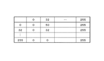
図10は階調値テーブルの例を示す図である。同図のテーブルでは、次のフレームの入力画像信号に応じた階調値が最上行に示されている。また、前回のフレームで設定された階調値が最左列に示されている。メモリ3には、このような複数の階調値テーブルが温度に対応付けて格納されている(図5参照)。 FIG. 10 is a diagram showing an example of the gradation value table. In the table shown in the figure, gradation values corresponding to the input image signal of the next frame are shown in the top row. Further, the gradation value set in the previous frame is shown in the leftmost column. The memory 3 stores a plurality of such gradation value tables in association with temperatures (see FIG. 5).
温度推定部2bが領域a1〜a25のそれぞれについて温度を算出した時、階調値テーブル選択部2dは、それらの温度に基づいて、複数の領域a1〜a25のそれぞれについて階調値テーブルを選択する。そして、階調値テーブル選択部2dは、図5に示すように、選択した階調値テーブルを、各領域a1〜a25に対応付けてメモリ3内に予め規定された記憶領域に格納する。すなわち、階調値テーブル選択部2dは、領域anの温度に基づいて階調値テーブルを選択すると、当該選択した階調値テーブルを領域anに対応付けてメモリ3に格納する。温度推定部2bにおいて新たな温度が算出されると、階調値テーブル選択部2dは、当該新たな温度に基づいて階調値テーブルを選択し、既に格納されている階調値テーブルを新たに選択した階調値テーブルに更新する。
When the
階調値算出部2eは、各領域の画素の階調値を当該領域に対応付けられた階調値テーブルを参照して算出する。すなわち、階調値算出部2eは、ある画素の階調値を算出する際、当該画素を含む領域に対応付けられた階調値テーブルを選択する。そして、階調値算出部2eは、選択した階調値テーブルを参照し、前回のフレームで当該画素に設定された階調値と、次のフレームの入力画像信号に応じた当該画素の階調値とに対応する階調値を算出する。階調値算出部2eは1フレーム間に全ての画素について以上の処理を実行する。
The gradation
なお、階調値テーブルでは、最小階調値(図10において0)から最大階調値(図10において255)までの全ての値が、前回のフレームの階調値と次のフレームの入力画像信号に応じた階調値として規定されてもよい。また、図10に示す階調値テーブルのように、前回のフレームの階調値と次のフレームの入力画像信号に応じた階調値とが、最小階調値から最大階調値まで段階的に設定されてもよい。すなわち、連続する2つの階調値の間に1よりも大きな差が設けられてもよい。このような階調値テーブルを用いる場合、前回のフレームの階調値や入力画像信号に応じた階調値が連続する2つの階調値の間の値であった場合には、階調値算出部2eは、連続する2つの階調値の間を補間する補間処理を実行する。
In the gradation value table, all values from the minimum gradation value (0 in FIG. 10) to the maximum gradation value (255 in FIG. 10) are the gradation value of the previous frame and the input image of the next frame. It may be defined as a gradation value according to the signal. Further, as in the gradation value table shown in FIG. 10, the gradation value of the previous frame and the gradation value corresponding to the input image signal of the next frame are stepped from the minimum gradation value to the maximum gradation value. May be set. That is, a difference larger than 1 may be provided between two consecutive gradation values. When such a gradation value table is used, if the gradation value of the previous frame or the gradation value corresponding to the input image signal is a value between two consecutive gradation values, the gradation value The
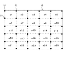
領域a1〜a25の温度推定に利用される係数の求め方について説明する。図11は係数を求める際に利用される温度検出器51の配置を説明するための図である。まず、液晶パネル10の表面上の複数の位置(この例では25箇所)に温度検出器51(例えば熱電対)を配置する。例えば、図11に示すように、領域a1〜a25のそれぞれに1つの温度検出器51を設ける。そして、複数の温度環境で、バックライトユニット20の制御モードを変化させながら液晶表示装置1を駆動する。例えば、0度環境下でバックライトユニット20の制御モード(高輝度モード、中輝度モード、低輝度モード)を順番に変化させ、その後、別の温度環境下でバックライトユニット20の制御モードを順番に変化させる。その際、一定時間間隔(例えば10秒間隔)で、液晶パネル10に設置した温度検出器51で実際の温度を測定するとともに温度センサ41の出力値を取得する。図12は温度センサ41の出力値と温度検出器51によって得られた実測温度の時間的な変化の例示している。このような温度測定により、図12に示すように、各温度検出器51が設けられた位置(温度測定位置)について多数の実測温度と、実測温度にそれぞれ対応する、温度センサ41の出力値とが得られる。そして、温度センサ41の出力値から実測温度を得る近似式を求める。各領域に1つの温度検出器51を設ける場合、すなわち、1つの領域に1つの温度測定位置が対応している場合、例えば領域anについては、温度センサ41の出力値と領域anに設けられた温度測定位置での実測温度とを用いて、係数Kan,Ran,Han,OFSanを含む近似式を求める。このような方法で係数を求めた場合、上述の温度推定部2bの処理においては、温度測定位置での推定温度が、当該温度測定位置を含む領域全体の推定温度と擬制される。すなわち、領域anの推定温度は、当該領域anに設けられた温度測定位置での推定温度によって代表される。なお、近似式の導出は、例えば最小二乗法により行うことができる。すなわち、温度センサ41の出力値に基づく領域anの温度(式(1)から得られる温度)と、領域anの実測温度との差の二乗の合計を最小にする値を、当該領域anについての係数とする。このように係数を導出すると、バックライトユニット20の制御モードを変更した時に温度推定誤差を小さくできる。
A method for obtaining coefficients used for temperature estimation of the regions a1 to a25 will be described. FIG. 11 is a diagram for explaining the arrangement of the
温度測定位置の設け方は以上説明したものに限られない。例えば、各領域に複数の温度検出器51が設けられてもよい。すなわち、1つの領域に複数の温度測定位置が対応付けられてもよい。図13に示す例では、各領域の角に温度測定位置が設けられ、1つの領域には4つの温度測定位置が対応付けられている。温度測定位置をこのように設ける場合、ある領域anの実際の温度は当該領域anに対応付けられた複数の温度測定位置での実測温度から算出する。例えば、複数の温度測定位置での実測温度の平均値を、当該領域anの実際の温度として用いる。そして、例えば領域anについては、温度センサ41の出力値と、算出された領域anの温度とを用いて、係数Kan,Ran,Han,OFSanを含む近似式を求める。
The method of providing the temperature measurement position is not limited to that described above. For example, a plurality of
以上説明したように、メモリ3には、温度センサ41の出力値と液晶パネル10に規定された複数の領域a1〜a25のそれぞれの温度との関係を表す温度関係情報が予め格納されている。制御装置2は、温度センサ41の出力値を取得し、温度関係情報と取得した出力値とに基づいて領域a1〜a25のそれぞれの温度を推定している。そのため、液晶パネル10に規定された複数の領域a1〜a25のそれぞれの温度を、少ない温度センサで得ることが可能となる。
As described above, the memory 3 stores in advance temperature relationship information representing the relationship between the output value of the
なお、本発明は以上説明した液晶表示装置1に限られず、種々の変更が可能である。 The present invention is not limited to the liquid crystal display device 1 described above, and various modifications can be made.
例えば、以上説明した液晶表示装置1には1つの温度センサ41が設けられていた。しかしながら、液晶表示装置1にはさらに多くの温度センサが設けられてもよい。
For example, the liquid crystal display device 1 described above is provided with one
図14は、この例の液晶表示装置が備える後フレーム31の背面図である。同図においては、これまで説明した箇所と同一箇所には同一符号を付している。また、以下では、これまで説明した液晶表示装置1と異なる点についてのみ説明し、説明のない事項は液晶表示装置1と同様である。
FIG. 14 is a rear view of the
図14に示す液晶表示装置は互いに離れて配置される複数の温度センサ41,42,43,44を備えている。この例においても、液晶パネル10に規定された領域の数は温度センサの数よりも多い。温度センサ42は、後フレーム31の下縁に取り付けられた回路基板12Bに取り付けられている。温度センサ41と温度センサ42は、後フレーム31の下縁に沿った方向に離れて位置している。温度センサ43は、TFT制御基板13に取り付けられている。温度センサ44は、アプリケーション基板15に取り付けられている。これらのセンサ41〜44の出力信号は直接的に或いは間接的に制御装置2に入力されている。同図の例では、温度センサ41,42,43の出力は制御装置2に直接的に入力され、温度センサ44の出力はアプリケーション基板15に実装されたICチップ15aを通して制御装置2に入力される。液晶表示装置には、さらに多くの温度センサが設けられてもよい。例えば、TFT制御基板13には、制御装置2を取り囲むように互いに離れて位置する複数(例えば3つ)の温度センサが設けられてもよい。
The liquid crystal display device shown in FIG. 14 includes a plurality of
この例では、複数の温度センサ41〜44の出力値と複数の領域a1〜a25のそれぞれの温度との関係を表す温度関係情報が、予めメモリ3に格納される。例えば、領域a1〜a25についての温度関係式の元となる基礎関係式と、領域a1〜a25にそれぞれ対応付けられた複数の係数群とが、温度関係情報としてメモリ3に格納される。上述した温度推定部2bは、各領域に対応する係数群で規定される温度関係式を用いて、複数の温度センサ41〜44の出力値に基づく当該領域の温度を算出する。
In this example, temperature relationship information representing the relationship between the output values of the plurality of
この例の基礎関係式は例えば式(3)により表される。
T=K1×Td1(i)+R1×F(Td1(i),H1)
+K2×Td2(i)+R2×F(Td2(i),H2)
+K3×Td3(i)+R3×F(Td3(i),H3)
+K4×Td4(i)+R4×F(Td4(i),H4)
+OFS・・・式(3)
Td1(i)、Td2(i)、Td3(i)及びTd4(i)は、それぞれ温度センサ41,42,43,44の最新の出力値である。K1〜4、R1〜4、H1〜4及びOFSは係数であり、各領域の温度を算出する際には当該領域に対応する具体的な係数が適用される。例えば、領域anを算出する場合には(この例では、n=1、2・・25)、領域anに対応付けられた係数(Kan1〜4、Ran1〜4、Han1〜4及びOFSan)が、式(3)の係数K1〜4、R1〜4、H1〜4及びOFSに適用される。Fは式(2)で示したのと同様のフィルタ関数であり、フィルタ係数H1〜4で規定されている。
The basic relational expression in this example is expressed by, for example, Expression (3).
T = K1 * Td1 (i) + R1 * F (Td1 (i), H1)
+ K2 * Td2 (i) + R2 * F (Td2 (i), H2)
+ K3 × Td3 (i) + R3 × F (Td3 (i), H3)
+ K4 × Td4 (i) + R4 × F (Td4 (i), H4)
+ OFS Formula (3)
Td1 (i), Td2 (i), Td3 (i), and Td4 (i) are the latest output values of the
式(3)で示されるように、この例の温度関係式は温度センサ41,42,43,44の出力値の一次関数である。そのため、温度推定の処理負荷が軽減されている。なお、温度関係式はこれに限られない。例えば、温度関係式はいずれかの温度センサの出力値について二次関数や三次関数でもよい。
As shown in Expression (3), the temperature relational expression in this example is a linear function of the output values of the
領域a1〜a25にそれぞれ対応付けられる複数の係数群と、複数の係数群が選択的に適用可能な基礎関係式(3)は、メモリ3に予め格納されている。これらの係数群も、図7を参照して説明した係数テーブルと同様に、各領域に対応付けて予めメモリ3に格納される。 A plurality of coefficient groups respectively associated with the regions a1 to a25 and a basic relational expression (3) to which the plurality of coefficient groups can be selectively applied are stored in the memory 3 in advance. These coefficient groups are also stored in advance in the memory 3 in association with each area, similarly to the coefficient table described with reference to FIG.
このような温度関係情報がメモリ3に格納されている場合であっても、センサ出力取得部2a及び温度推定部2bが実行する処理は、上述の形態と同様である。すなわち、センサ出力取得部2aは予め設定されたサンプリング周期で温度センサ41,42,43,44の出力値を取得する。領域anの温度を推定する処理においては、温度推定部2bは、まず、複数の係数群から領域anに対応する係数群を選択する。そして、温度推定部2bは、選択した係数群と式(3)で示される基礎関係式とで規定される温度関係式を用いて、複数の温度センサ41,42,43,44の出力値から領域anの温度を算出する。温度推定部2bは、全ての領域a1〜a25について上述の処理を実行する。
Even when such temperature-related information is stored in the memory 3, the processes executed by the sensor
この例のように複数の温度センサ41,42,43,44が液晶表示装置に設けられる場合、温度推定部2bは、次のような処理により、液晶表示装置の前回の駆動終了時からの十分な時間が経過したか否か、すなわち現時点が定常期間に該当しているか否かを判定してもよい。
When a plurality of
液晶表示装置の前回の駆動終了時から十分な時間が経過した場合には、温度センサ41,42,43,44の出力値は環境温度に依存した値となり、互いに等しくなる。温度センサ41,42,43,44の取付位置やLED21からの距離は互いに異なっている。すなわち、温度センサ41,42,43,44は、LED21の熱の伝わり易さにおいて、互いに異なっている。そのため、定常期間においては、温度センサ41,42,43,44の出力値には差が生じる。そこで、温度推定部2bは、いずれか2つの温度センサの出力値の差が閾値より大きい場合に、現時点が定常期間に該当していると判断してもよい。つまり、温度推定部2bは、液晶表示装置の駆動開始時からの経過時間に応じて変化する情報として、2つの温度センサの出力値の差を用いてもよい。例えば、LED21からの熱の影響を最も受けやすい位置に設けられた温度センサ(この例では温度センサ41又は42)の出力値と、当該温度センサから離れて位置する別の温度センサの出力値(この例では温度センサ43又は44)との差が閾値より大きい場合に、温度推定部2bは現時点が定常期間に該当していると判断してもよい。
When a sufficient time has elapsed since the end of the previous driving of the liquid crystal display device, the output values of the
各領域a1〜a25に対応付けられた係数の求め方は、上述と同様である。すなわち、複数の温度環境で、バックライトユニット20の制御モードを変化させながら液晶表示装置を駆動する。その際、一定時間間隔で、液晶パネル10の各領域a1〜a25の実際の温度を測定するとともに温度センサ41,42,43,44の出力値を取得する。そして、温度センサ41,42,43,44の出力値を用いて、実測温度についての近似式を求める。
The method for obtaining the coefficients associated with the areas a1 to a25 is the same as described above. That is, the liquid crystal display device is driven while changing the control mode of the
1 液晶表示装置、2 制御装置、2a センサ出力取得部、2b 温度推定部、2c 補正処理部、2d 階調値テーブル選択部、2e 階調値算出部、3 メモリ、10 液晶パネル、12A,12B 回路基板、12b ICチップ、13 TFT制御基板、14 電源基板、15 アプリケーション基板、
20 バックライトユニット、21 LED、21a 回路基板、22 導光板、23 反射板、24 放熱板、31 後フレーム、32 螺子、33 基板カバー、41,42,43,44 温度センサ、51 係数算出用の温度検出器、a1〜a25 液晶パネルに規定された領域。
DESCRIPTION OF SYMBOLS 1 Liquid crystal display device, 2 Control apparatus, 2a Sensor output acquisition part, 2b Temperature estimation part, 2c Correction processing part, 2d Tone value table selection part, 2e Tone value calculation part, 3 Memory, 10 Liquid crystal panel, 12A, 12B Circuit board, 12b IC chip, 13 TFT control board, 14 power supply board, 15 application board,
20 backlight unit, 21 LED, 21a circuit board, 22 light guide plate, 23 reflector, 24 heat sink, 31 rear frame, 32 screw, 33 substrate cover, 41, 42, 43, 44 temperature sensor, 51 for coefficient calculation Temperature detector, a1 to a25 A region defined in the liquid crystal panel.
Claims (10)
前記少なくとも1つの温度センサよりも数の多い複数の領域が規定された液晶パネルと、
前記少なくとも1つの温度センサの出力値と前記複数の領域のそれぞれの温度との関係を表す情報である温度関係情報が予め格納されたメモリと、
前記少なくとも1つの温度センサの出力値を取得し、前記温度関係情報と前記取得した出力値とに基づいて前記複数の領域のそれぞれの温度を推定する制御装置と、
を備えることを特徴とする液晶表示装置。 At least one temperature sensor;
A liquid crystal panel in which a plurality of regions having a larger number than the at least one temperature sensor are defined;
A memory in which temperature relationship information, which is information representing a relationship between an output value of the at least one temperature sensor and a temperature of each of the plurality of regions, is stored in advance;
A controller that obtains an output value of the at least one temperature sensor and estimates the temperature of each of the plurality of regions based on the temperature-related information and the obtained output value;
A liquid crystal display device comprising:
前記制御装置は、前記少なくとも1つの温度センサの出力値と前記複数の領域の温度との関係を表す、前記温度関係情報によって規定される複数の関係式を用いて、前記複数の領域のそれぞれの温度を推定する、
ことを特徴とする液晶表示装置。 The liquid crystal display device according to claim 1.
The control device uses a plurality of relational expressions defined by the temperature relation information that represents a relationship between an output value of the at least one temperature sensor and a temperature of the plurality of areas, and uses each of the plurality of relational expressions. Estimate the temperature,
A liquid crystal display device characterized by the above.
前記メモリには、前記複数の領域にそれぞれ対応付けられた複数の係数が前記温度関係情報として格納されており、
前記複数の関係式は前記複数の係数と当該複数の係数が選択的に適用可能な基礎関係式とにより規定される、
ことを特徴とする液晶表示装置。 The liquid crystal display device according to claim 2,
In the memory, a plurality of coefficients respectively associated with the plurality of regions are stored as the temperature-related information,
The plurality of relational expressions are defined by the plurality of coefficients and a basic relational expression to which the plurality of coefficients can be selectively applied.
A liquid crystal display device characterized by the above.
前記制御装置は、前記液晶表示装置の駆動開始時からの経過時間に応じて変化する情報に基づいて現時点が予め定められた定常期間に該当するか否かを判定し、
前記制御装置は、現時点が前記定常期間に該当する場合と現時点が前記定常期間に該当しない場合とでは、前記複数の領域の温度を推定するための処理として異なる処理を実行する、
ことを特徴とする液晶表示装置。 The liquid crystal display device according to any one of claims 1 to 3,
The control device determines whether or not the current time corresponds to a predetermined steady period based on information that changes according to an elapsed time from the start of driving of the liquid crystal display device,
The control device performs different processing as processing for estimating the temperatures of the plurality of regions when the current time corresponds to the steady period and when the current time does not correspond to the steady period.
A liquid crystal display device characterized by the above.
前記少なくとも1つの温度センサとして、互いに離れて配置される2つの温度センサを備え、
前記制御装置は、前記液晶表示装置の駆動開始時からの経過時間に応じて変化する前記情報として、前記2つの温度センサの出力値の差を用いる、
ことを特徴とする液晶表示装置。 The liquid crystal display device according to claim 4.
The at least one temperature sensor includes two temperature sensors arranged apart from each other,
The control device uses a difference between output values of the two temperature sensors as the information that changes in accordance with an elapsed time from the start of driving of the liquid crystal display device.
A liquid crystal display device characterized by the above.
導光板と前記導光板の少なくとも一辺に配置された光源とを有するバックライトユニットをさらに備える、
ことを特徴とする液晶表示装置。 The liquid crystal display device according to claim 1.
A backlight unit having a light guide plate and a light source disposed on at least one side of the light guide plate;
A liquid crystal display device characterized by the above.
前記少なくとも1つの温度センサが取り付けられ、前記導光板の前記少なくとも一辺に沿って配置される回路基板をさらに備える、
ことを特徴とする液晶表示装置。 The liquid crystal display device according to claim 6.
The circuit board is further provided with the at least one temperature sensor and disposed along the at least one side of the light guide plate.
A liquid crystal display device characterized by the above.
前記バックライトユニットの背面を覆う金属製の後フレームをさらに備え、
前記回路基板は前記後フレームに固定されている、
ことを特徴とする液晶表示装置。 The liquid crystal display device according to claim 7.
A metal rear frame covering the back of the backlight unit;
The circuit board is fixed to the rear frame;
A liquid crystal display device characterized by the above.
複数の回路基板をさらに備え、
前記少なくとも1つの温度センサは前記複数の回路基板のうち最も光源に近い回路基板に取り付けられている、
ことを特徴とする液晶表示装置。 The liquid crystal display device according to claim 6.
A plurality of circuit boards;
The at least one temperature sensor is attached to a circuit board closest to the light source among the plurality of circuit boards;
A liquid crystal display device characterized by the above.
前記光源は複数のLEDからなる
ことを特徴とする液晶表示装置。 The liquid crystal display device according to claim 6.
The light source is composed of a plurality of LEDs.
Priority Applications (2)
| Application Number | Priority Date | Filing Date | Title |
|---|---|---|---|
| JP2011052650A JP2012189766A (en) | 2011-03-10 | 2011-03-10 | Liquid crystal display device |
| US13/415,523 US8879027B2 (en) | 2011-03-10 | 2012-03-08 | Liquid crystal display device |
Applications Claiming Priority (1)
| Application Number | Priority Date | Filing Date | Title |
|---|---|---|---|
| JP2011052650A JP2012189766A (en) | 2011-03-10 | 2011-03-10 | Liquid crystal display device |
Publications (1)
| Publication Number | Publication Date |
|---|---|
| JP2012189766A true JP2012189766A (en) | 2012-10-04 |
Family
ID=46795264
Family Applications (1)
| Application Number | Title | Priority Date | Filing Date |
|---|---|---|---|
| JP2011052650A Withdrawn JP2012189766A (en) | 2011-03-10 | 2011-03-10 | Liquid crystal display device |
Country Status (2)
| Country | Link |
|---|---|
| US (1) | US8879027B2 (en) |
| JP (1) | JP2012189766A (en) |
Cited By (2)
| Publication number | Priority date | Publication date | Assignee | Title |
|---|---|---|---|---|
| WO2014057718A1 (en) * | 2012-10-12 | 2014-04-17 | Kabushiki Kaisha Toshiba | Image display apparatus and electronic apparatus |
| WO2015059965A1 (en) * | 2013-10-24 | 2015-04-30 | シャープ株式会社 | Display device and television receiver |
Families Citing this family (11)
| Publication number | Priority date | Publication date | Assignee | Title |
|---|---|---|---|---|
| KR101612001B1 (en) | 2010-01-18 | 2016-04-14 | 삼성디스플레이 주식회사 | Method of driving display panel, driving unit of display panel for performing the method and display apparatus having the driving unit |
| JP2013160502A (en) * | 2012-02-01 | 2013-08-19 | Panasonic Liquid Crystal Display Co Ltd | Display unit having temperature sensor |
| US20140104883A1 (en) * | 2012-10-12 | 2014-04-17 | Kabushiki Kaisha Toshiba | Image display apparatus and electronic apparatus |
| CN103021363B (en) * | 2012-12-13 | 2015-06-10 | 京东方科技集团股份有限公司 | Overdrive method, device and system |
| KR102087196B1 (en) * | 2013-12-19 | 2020-03-11 | 삼성디스플레이 주식회사 | Liquid crystal display |
| US20160381317A1 (en) * | 2014-03-19 | 2016-12-29 | Sharp Kabushiki Kaisha | Display device and television receiving device |
| WO2016183239A1 (en) * | 2015-05-12 | 2016-11-17 | Dolby Laboratories Licensing Corporation | Metadata filtering for display mapping for high dynamic range images |
| KR102411320B1 (en) * | 2017-08-31 | 2022-06-22 | 엘지디스플레이 주식회사 | Display device |
| KR102576037B1 (en) * | 2018-10-30 | 2023-09-08 | 삼성전자주식회사 | Display apparatus |
| US11829032B2 (en) | 2019-10-31 | 2023-11-28 | K-Tronics (Suzhou) Technology Co., Ltd. | Backlight module including fixing member, display module and assembling method thereof |
| CN110618562A (en) * | 2019-10-31 | 2019-12-27 | 京东方科技集团股份有限公司 | Backlight module, assembling method thereof and display device |
Family Cites Families (11)
| Publication number | Priority date | Publication date | Assignee | Title |
|---|---|---|---|---|
| KR100516533B1 (en) * | 1997-03-26 | 2005-12-16 | 세이코 엡슨 가부시키가이샤 | Liquid crystal device, electrooptic device, and projection display device using the same |
| JP2000089197A (en) | 1998-09-09 | 2000-03-31 | Denso Corp | Matrix type liquid crystal display device |
| US7012600B2 (en) * | 1999-04-30 | 2006-03-14 | E Ink Corporation | Methods for driving bistable electro-optic displays, and apparatus for use therein |
| JP3695224B2 (en) | 1999-06-16 | 2005-09-14 | セイコーエプソン株式会社 | Electro-optical device, electronic apparatus, and electro-optical panel driving method |
| JP3270435B2 (en) * | 1999-10-04 | 2002-04-02 | 松下電器産業株式会社 | Display device and brightness control method thereof |
| JP2005031136A (en) * | 2003-07-07 | 2005-02-03 | Pioneer Electronic Corp | Panel display device |
| JP4182930B2 (en) * | 2004-07-12 | 2008-11-19 | ソニー株式会社 | Display device and backlight device |
| JP4651673B2 (en) * | 2005-08-25 | 2011-03-16 | シャープ株式会社 | Image display device |
| KR100735460B1 (en) * | 2005-09-09 | 2007-07-03 | 삼성전기주식회사 | A circuit for controlling led driving with temperature compensation |
| JP5139666B2 (en) * | 2006-11-06 | 2013-02-06 | Necディスプレイソリューションズ株式会社 | Brightness adjusting device and brightness adjusting method |
| CN102549649B (en) * | 2009-10-07 | 2014-10-15 | 夏普株式会社 | Liquid crystal display device |
-
2011
- 2011-03-10 JP JP2011052650A patent/JP2012189766A/en not_active Withdrawn
-
2012
- 2012-03-08 US US13/415,523 patent/US8879027B2/en active Active
Cited By (4)
| Publication number | Priority date | Publication date | Assignee | Title |
|---|---|---|---|---|
| WO2014057718A1 (en) * | 2012-10-12 | 2014-04-17 | Kabushiki Kaisha Toshiba | Image display apparatus and electronic apparatus |
| WO2015059965A1 (en) * | 2013-10-24 | 2015-04-30 | シャープ株式会社 | Display device and television receiver |
| CN105612458A (en) * | 2013-10-24 | 2016-05-25 | 夏普株式会社 | Display device and television receiver |
| CN105612458B (en) * | 2013-10-24 | 2018-10-16 | 夏普株式会社 | Display device and radiovisor |
Also Published As
| Publication number | Publication date |
|---|---|
| US8879027B2 (en) | 2014-11-04 |
| US20120229733A1 (en) | 2012-09-13 |
Similar Documents
| Publication | Publication Date | Title |
|---|---|---|
| JP2012189766A (en) | Liquid crystal display device | |
| US9267849B2 (en) | Display device with temperature sensor | |
| JP5080681B1 (en) | Display device, computer program, recording medium, and temperature estimation method | |
| JP5214809B2 (en) | Liquid crystal display | |
| US8648794B2 (en) | Screen light computation device or method | |
| JP2007079572A5 (en) | ||
| JP2012237972A (en) | Temperature estimation device, control method thereof and image display device | |
| JP6100077B2 (en) | Light source device and control method thereof | |
| US9858891B2 (en) | Display control apparatus and display control method to detect temperature of display region | |
| US20120146973A1 (en) | Display device | |
| JP6277549B2 (en) | Surface illumination device and liquid crystal display device | |
| JP2007163712A (en) | Display panel, self-luminous display device, gradation value/degradation rate conversion table updating device, input display data correction device, and program | |
| US11881185B2 (en) | Display module and display method thereof, and display device | |
| JP4913215B2 (en) | Liquid crystal display device and control method thereof | |
| JP2014134764A (en) | Display device and method of controlling the same | |
| JP2007206464A (en) | Spontaneous display device, estimation degradation information correction device, input display data compensation device, and program | |
| JP2007240798A (en) | Spontaneous light emission display device, gray scale value/deterioration quantity conversion table updating device, and input display data correcting device and program | |
| TWI427611B (en) | Overdriving value generating method | |
| JP5146871B2 (en) | LIGHTING DEVICE AND LIGHTING DEVICE CONTROL METHOD | |
| JP2021021854A (en) | Display device and control method thereof | |
| JP2007206463A (en) | Self-luminous display device, input display data correction device, and program | |
| JP6469477B2 (en) | Electronic device and display control method | |
| WO2014132438A1 (en) | Optical measurement apparatus, and method for adjusting optical characteristics | |
| JP2007279213A (en) | Luminance inspecting device for display panel, and display panel manufacturing method using the same | |
| JP2014149485A (en) | Display device and control method therefor |
Legal Events
| Date | Code | Title | Description |
|---|---|---|---|
| A300 | Withdrawal of application because of no request for examination |
Free format text: JAPANESE INTERMEDIATE CODE: A300 Effective date: 20140513 |