JP2012189666A - Display device - Google Patents
Display device Download PDFInfo
- Publication number
- JP2012189666A JP2012189666A JP2011051177A JP2011051177A JP2012189666A JP 2012189666 A JP2012189666 A JP 2012189666A JP 2011051177 A JP2011051177 A JP 2011051177A JP 2011051177 A JP2011051177 A JP 2011051177A JP 2012189666 A JP2012189666 A JP 2012189666A
- Authority
- JP
- Japan
- Prior art keywords
- display
- display panel
- light
- liquid crystal
- display device
- Prior art date
- Legal status (The legal status is an assumption and is not a legal conclusion. Google has not performed a legal analysis and makes no representation as to the accuracy of the status listed.)
- Pending
Links
Images


Landscapes
- Devices For Indicating Variable Information By Combining Individual Elements (AREA)
- Details Of Measuring Devices (AREA)
Abstract
Description
本発明は、表示装置に関し、特に複数の表示パネルを備えてなる表示装置に関するものである。 The present invention relates to a display device, and particularly to a display device including a plurality of display panels.
表示パネルを複数備えてなる表示装置は、例えば特許文献1に記載されている。この表示装置は、複数の有機ELパネルを並置して表示領域を大型化するものである。通常、複数の表示パネルを並置すると、保持部材などによって各表示パネル間に一定の非表示領域が生じる。従来は、文字板に設けた透視窓などによって表示パネルを視認可能とし、非表示領域は文字板で隠す構造が知られている。
A display device including a plurality of display panels is described in
しかしながら、前記各表示パネル間に段差や隙間が生じることによって、表示装置の表示領域内の見栄えが損なわれ、表示装置の一体感を表現しにくいという問題点があった。 However, there is a problem in that the appearance in the display area of the display device is impaired due to the formation of steps or gaps between the display panels, and it is difficult to express the sense of unity of the display device.
そこで本発明は、光源の光によって照明される第1の表示パネルと、前記第1の表示パネルと並置して設けられる第2の表示パネルと、前記第1の表示パネル及び前記第2の表示パネルの表示面側を覆うように設けられた前面板とを備えた表示装置において、
前記第1の表示パネルと前記第2の表示パネルとの間に中間部を有し、
前記中間部と対応する箇所に意匠部を有し、
前記意匠部は、前記前面板を透過する光によって照明されるものである。
Therefore, the present invention provides a first display panel that is illuminated by light from a light source, a second display panel that is provided in parallel with the first display panel, the first display panel, and the second display. In a display device comprising a front plate provided so as to cover the display surface side of the panel,
An intermediate portion between the first display panel and the second display panel;
Having a design part at a location corresponding to the intermediate part,
The said design part is illuminated by the light which permeate | transmits the said front board.
このように構成することによって、複数の表示パネルが並置された表示装置であっても、表示パネルの間にある意匠部が透過照明されることによって、複数の表示パネルに一体感を持たせることができる。 By configuring in this way, even in a display device in which a plurality of display panels are juxtaposed, a plurality of display panels can be given a sense of unity by transmitting and illuminating the design portion between the display panels. Can do.
また本発明は、前記前面板は、前記中間部に屈曲部を有し、前記意匠部に光を導光する導光部が前記中間部の背面側に設けられたものである。 In the present invention, the front plate has a bent portion in the intermediate portion, and a light guide portion for guiding light to the design portion is provided on the back side of the intermediate portion.
このように構成することによって、前記意匠部を専用光源を設けることなく照明することができるので、コストダウンを達成することができる。 By comprising in this way, since the said design part can be illuminated without providing a dedicated light source, cost reduction can be achieved.
また本発明は、前記第1の表示パネルは、液晶表示パネルからなることを特徴とする請求項1及び2に記載の表示装置。
The display device according to
本発明は、複数の表示パネルを用いた表示装置に関するものであり、各表示パネルによる表示に一体感を持たせ、表示装置の外観を良好にすることが可能となる。 The present invention relates to a display device using a plurality of display panels, and it is possible to give a sense of unity to the display by each display panel and to improve the appearance of the display device.
以下、本発明の実施形態に係る表示装置を燃料残量などの車両情報を表示する車両用計器に適用したものを例に挙げて添付の図面を参照して説明する。 Hereinafter, an example in which a display device according to an embodiment of the present invention is applied to a vehicle instrument that displays vehicle information such as a fuel remaining amount will be described with reference to the accompanying drawings.
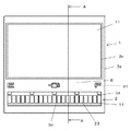
本発明の表示装置は、TFT型液晶表示ユニットから構成された第1の表示パネル1と、バーグラフ表示部23を有するセグメント表示をさせる第2の表示パネル2と、第1の表示パネル1と第2の表示パネル2を連続して覆う前面板3とから主に構成される。
The display device of the present invention includes a
第1の表示パネル1は、本実施形態においては、液晶表示部であり、2枚のガラス基板間に液晶分子を封入し、各々のガラス基板に偏光膜を貼り合わせた矩形の液晶表示パネル11と、この液晶表示パネル11の裏面側に配置され光透過性を有する図示しない拡散板と、液晶表示パネル11および拡散板が支持される図示しないホルダーと、液晶表示パネル11の表面側周縁を抑える枠状の縁部を有する図示しないパネル抑えと、回路基板7上に実装され液晶表示パネル11を背後から透過照明する光源としての発光ダイオードと、液晶表示パネル11と回路基板とを繋ぐ導電性の接続部材としての端子とから主に構成される。それらは、液晶ユニットUとして構成されている。この場合、液晶表示パネル11は、画像表示可能なTFT型の駆動モジュールが実装され、別途設けられた駆動回路によって区画形成された画素毎に表示制御される。
In the present embodiment, the
第2の表示パネル2は、本実施形態においては、セグメント表示部であり、液晶表示パネル21と、この液晶表示パネル21の裏面側に配置された拡散板(図示せず)と、液晶表示パネル21および拡散板が保持されるホルダー(図示せず)と、このホルダーの背後に配置され液晶表示パネル21および拡散板を背後から透過照明するセグメント表示用光源6としての発光ダイオードと、この光源の光を液晶表示パネル21に導光する導光体22や液晶表示パネル21を駆動させる制御手段(図示せず)などが実装された硬質の回路基板7と、液晶表示パネル21と回路基板7とを電気的に接続する接続端子8とを備え、セルケース9によって保持されている。
In the present embodiment, the
液晶表示パネル11は、周知の如く、ITOからなる透明電極(所謂セグメント電極)が形成された前側ガラス基板と、同じく透明電極(所謂コモン電極)が形成された後側ガラス基板との間に液晶分子を封入し、各々のガラス基板に偏光膜を貼ったものである。そして、後側ガラス基板の端部に引き回された電極を通して各透明電極に外部計測量に応じた信号が印加されると、計測量である例えば車両の燃料残量がバー表示されるようになっており、液晶表示パネル11は、例えば燃料残量をバー表示するバーグラフ表示部23を有している。
As is well known, the liquid
前面板3は、光透過性の合成樹脂パネルからなる基材の表面又は裏面に、例えば黒色など不透過の印刷が施された非表示領域3aと、第1及び第2の表示パネルが視認可能なように設けられた表示枠3dと、非表示領域3aの印刷時に所定の意匠が抜き印刷された意匠部31とを備えている。また、前面板3の一辺(図1中右下)には、エッジライト用光源6aの光を意匠部31の方向に反射させるための反射面32が設けられている。意匠部31は、第2の表示パネル2の表示内容に関連する意匠が形成され、この場合、バーグラグ表示部23の指標部や表示内容を示すアイコンが形成されている。これにより、意匠部31と第2の表示パネル2との一体感を得ることができる。
The
回路基板7は、硬質の基板からなり、図示しないが回路パターン等が印刷されている。また、回路基板7には、セグメント表示用光源6の他に、エッジライト照明用光源6aも実装されてある。
The
このように構成された表示装置において、エッジライト照明用光源6aから出射した光は、透明パネル3に設けられた反射面32によって意匠部31の方向に反射され、その光によって意匠部31が透過照明される。
In the display device configured as described above, the light emitted from the edge light
このように本発明は、光源の光によって照明される第1の表示パネルと、第1の表示パネルと並置して設けられる第2の表示パネルと、第1の表示パネル及び第2の表示パネルを覆うように設けられた前面板3とを備えた表示装置において、第1の表示パネルと第2の表示パネルとの間に中間部Sを有し、中間部Sと対応する箇所に意匠部31を有し、意匠部31は、前面板3を透過する光によって照明されることによって、複数の表示パネルが並置された表示装置であっても、表示パネルの間にある意匠部31が透過照明されることによって、意匠部31と各表示パネルとの間において段差や境界が見えないため、表示パネルに一体感を持たせることができる。
As described above, the present invention provides the first display panel illuminated by the light of the light source, the second display panel provided in parallel with the first display panel, the first display panel, and the second display panel. In the display device provided with the
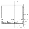
次に、第2の実施形態を説明する。 第1の実施形態と同一部材には同一の符号を付し、詳細は省略する。 Next, a second embodiment will be described. The same members as those in the first embodiment are denoted by the same reference numerals, and details thereof are omitted.
本実施形態の場合、第2の表示パネル2は第1の表示パネル1よりも観察者側に傾いて配置され、その傾きによって生じる中間部Sを挟んで第1の表示パネル1と第2の表示パネル2が並置されている。
In the case of the present embodiment, the
前面板3は、光透過性の合成樹脂パネルからなる基材の表面に、不透過の印刷が施された文字板32であり、第1の表示パネル1の表示枠3cと、第2の表示パネル2の表示枠3dと、所定の意匠が抜き印刷された意匠部31とを備え、意匠部31を軸点として観察者側方向に傾く屈曲部32aが、例えば絞り成形などの手法によって形成されている。この表示枠3c,3dと意匠部31の背景となる中間部Sの遮光印刷とを連続的に形成することによって、一体感を得ることができる。
The
また、前面板3の表示面と反対側には、回路基板7に実装されたセグメント表示用光源6からの光を意匠部31に導光するための導光部材50が設けられている。導光部材50は、液晶表示パネル21を保持するセルケース9と一体成形されている。
A
このように構成された表示装置において、セグメント表示用光源6から出射した光は、導光部材50によって意匠部31の方向に導かれ、意匠部31を透過照明する。
In the display device configured as described above, the light emitted from the segment
このように本発明は、前面板3は、第1の表示パネル1と第2の表示パネル2とが中間部Sを介して配置される箇所と対応する屈曲部32aを有し、意匠部31に光を導光する導光部材50が屈曲部32aの背面側に設けられたことによって、各表示パネルの間に空間が生まれ、その空間に意匠部31に光を導光するための導光部材50を配置することで、意匠部31を照明することができるので、第1の実施形態のようにエッジライト照明を設ける必要がなくコストダウンを達成することができる。また、観察者はセグメント表示部2を液晶表示部1よりも手前側に視認することができるので、奥行き感のある表示装置となる。また、構成全体を屈曲した大きな一枚のディスプレイのように見せることができる。
Thus, according to the present invention, the
1 液晶表示部(第1の表示パネル)
2 セグメント表示部(第2の表示パネル)
3 前面板
3a 非表示領域
3c 表示枠
3d 表示枠
5 導光体
6 セグメント表示用光源
6a エッジライト用光源
7 回路基板
8 接続端子
9 セルケース
22 導光体
23 バーグラフ表示部
31 意匠部
32 文字板
32a 屈曲部
50 導光部材
S 中間部
U 液晶ユニット
1 Liquid crystal display (first display panel)
2-segment display (second display panel)
3
Claims (3)
前記第1の表示パネルと前記第2の表示パネルとの間に中間部を有し、
前記非表示領域と対応する箇所に意匠部を有し、
前記意匠部は、前記前面板を透過する光によって照明されることを特徴とする表示装置。 A first display panel illuminated by light from a light source; a second display panel provided in parallel with the first display panel; and the display surface side of the first display panel and the second display panel In a display device comprising a front plate provided so as to cover
An intermediate portion between the first display panel and the second display panel;
Having a design portion at a location corresponding to the non-display area;
The said design part is illuminated with the light which permeate | transmits the said front board, The display apparatus characterized by the above-mentioned.
Priority Applications (1)
| Application Number | Priority Date | Filing Date | Title |
|---|---|---|---|
| JP2011051177A JP2012189666A (en) | 2011-03-09 | 2011-03-09 | Display device |
Applications Claiming Priority (1)
| Application Number | Priority Date | Filing Date | Title |
|---|---|---|---|
| JP2011051177A JP2012189666A (en) | 2011-03-09 | 2011-03-09 | Display device |
Publications (1)
| Publication Number | Publication Date |
|---|---|
| JP2012189666A true JP2012189666A (en) | 2012-10-04 |
Family
ID=47082929
Family Applications (1)
| Application Number | Title | Priority Date | Filing Date |
|---|---|---|---|
| JP2011051177A Pending JP2012189666A (en) | 2011-03-09 | 2011-03-09 | Display device |
Country Status (1)
| Country | Link |
|---|---|
| JP (1) | JP2012189666A (en) |
Cited By (3)
| Publication number | Priority date | Publication date | Assignee | Title |
|---|---|---|---|---|
| WO2014125523A1 (en) * | 2013-02-12 | 2014-08-21 | パナソニック株式会社 | Display device |
| JP2017062121A (en) * | 2015-09-23 | 2017-03-30 | 日本精機株式会社 | Display device |
| JP2018179741A (en) * | 2017-04-13 | 2018-11-15 | 日本精機株式会社 | Display device |
Citations (5)
| Publication number | Priority date | Publication date | Assignee | Title |
|---|---|---|---|---|
| JPH0363186U (en) * | 1989-10-24 | 1991-06-20 | ||
| JPH0732682U (en) * | 1993-11-19 | 1995-06-16 | 日本精機株式会社 | Display device |
| JPH07239664A (en) * | 1994-02-25 | 1995-09-12 | Sanyo Electric Co Ltd | Display device |
| JP2003057629A (en) * | 2001-08-10 | 2003-02-26 | Alpine Electronics Inc | Display panel device |
| JP2005316066A (en) * | 2004-04-28 | 2005-11-10 | Nippon Seiki Co Ltd | Display device |
-
2011
- 2011-03-09 JP JP2011051177A patent/JP2012189666A/en active Pending
Patent Citations (5)
| Publication number | Priority date | Publication date | Assignee | Title |
|---|---|---|---|---|
| JPH0363186U (en) * | 1989-10-24 | 1991-06-20 | ||
| JPH0732682U (en) * | 1993-11-19 | 1995-06-16 | 日本精機株式会社 | Display device |
| JPH07239664A (en) * | 1994-02-25 | 1995-09-12 | Sanyo Electric Co Ltd | Display device |
| JP2003057629A (en) * | 2001-08-10 | 2003-02-26 | Alpine Electronics Inc | Display panel device |
| JP2005316066A (en) * | 2004-04-28 | 2005-11-10 | Nippon Seiki Co Ltd | Display device |
Cited By (4)
| Publication number | Priority date | Publication date | Assignee | Title |
|---|---|---|---|---|
| WO2014125523A1 (en) * | 2013-02-12 | 2014-08-21 | パナソニック株式会社 | Display device |
| JPWO2014125523A1 (en) * | 2013-02-12 | 2017-02-02 | パナソニックIpマネジメント株式会社 | Display device |
| JP2017062121A (en) * | 2015-09-23 | 2017-03-30 | 日本精機株式会社 | Display device |
| JP2018179741A (en) * | 2017-04-13 | 2018-11-15 | 日本精機株式会社 | Display device |
Similar Documents
| Publication | Publication Date | Title |
|---|---|---|
| JP4895327B2 (en) | Liquid crystal display | |
| JP6263842B2 (en) | Display device | |
| JP6120064B2 (en) | Display device | |
| JP5963849B2 (en) | Operation panel and information device provided with the same | |
| JP2016161761A (en) | Display device | |
| JP5116645B2 (en) | Vehicle display device | |
| JP2012189666A (en) | Display device | |
| CN107532928B (en) | Display device for vehicle | |
| JP5526417B2 (en) | Display device and navigation device | |
| JP2015031772A (en) | Liquid crystal display device | |
| JP5136153B2 (en) | Vehicle display device | |
| JP6504127B2 (en) | Vehicle display device | |
| WO2018139432A1 (en) | Display device | |
| JP7041840B2 (en) | Display device | |
| JP5513812B2 (en) | Display device | |
| JP2018097233A (en) | Liquid crystal display device | |
| JP2016006385A (en) | Lighting system of vehicular instrument | |
| JP2020197623A (en) | Display device | |
| JP2016008947A (en) | Display device | |
| WO2019151111A1 (en) | Display device | |
| JP6248693B2 (en) | Display device | |
| JP5382532B2 (en) | Indicating instrument | |
| JP2022052865A (en) | Display device | |
| JP2014106171A (en) | Vehicle instrument illumination device | |
| JP2015031592A (en) | Display device for vehicle |
Legal Events
| Date | Code | Title | Description |
|---|---|---|---|
| A621 | Written request for application examination |
Free format text: JAPANESE INTERMEDIATE CODE: A621 Effective date: 20140117 |
|
| A977 | Report on retrieval |
Free format text: JAPANESE INTERMEDIATE CODE: A971007 Effective date: 20140919 |
|
| A131 | Notification of reasons for refusal |
Free format text: JAPANESE INTERMEDIATE CODE: A131 Effective date: 20140930 |
|
| A02 | Decision of refusal |
Free format text: JAPANESE INTERMEDIATE CODE: A02 Effective date: 20150219 |