JP2012189075A - Cylinder head for an internal combustion engine, with integrated exhaust manifold and subgroups of exhaust conduits merging into manifold portions which are superimposed and spaced apart from each other - Google Patents
Cylinder head for an internal combustion engine, with integrated exhaust manifold and subgroups of exhaust conduits merging into manifold portions which are superimposed and spaced apart from each other Download PDFInfo
- Publication number
- JP2012189075A JP2012189075A JP2011283907A JP2011283907A JP2012189075A JP 2012189075 A JP2012189075 A JP 2012189075A JP 2011283907 A JP2011283907 A JP 2011283907A JP 2011283907 A JP2011283907 A JP 2011283907A JP 2012189075 A JP2012189075 A JP 2012189075A
- Authority
- JP
- Japan
- Prior art keywords
- head
- cooling jacket
- exhaust
- cylinder head
- manifold
- Prior art date
- Legal status (The legal status is an assumption and is not a legal conclusion. Google has not performed a legal analysis and makes no representation as to the accuracy of the status listed.)
- Granted
Links
- 238000002485 combustion reaction Methods 0.000 title claims abstract description 12
- 238000001816 cooling Methods 0.000 claims abstract description 64
- 239000000110 cooling liquid Substances 0.000 claims description 3
- 239000012530 fluid Substances 0.000 abstract description 2
- 239000002826 coolant Substances 0.000 description 20
- 239000004576 sand Substances 0.000 description 9
- 238000005192 partition Methods 0.000 description 3
- XAGFODPZIPBFFR-UHFFFAOYSA-N aluminium Chemical compound [Al] XAGFODPZIPBFFR-UHFFFAOYSA-N 0.000 description 2
- 229910052782 aluminium Inorganic materials 0.000 description 2
- 238000005266 casting Methods 0.000 description 2
- 238000004519 manufacturing process Methods 0.000 description 2
- 238000013021 overheating Methods 0.000 description 2
- 229910000831 Steel Inorganic materials 0.000 description 1
- 230000010354 integration Effects 0.000 description 1
- 230000003993 interaction Effects 0.000 description 1
- 239000007788 liquid Substances 0.000 description 1
- 239000000463 material Substances 0.000 description 1
- 238000007528 sand casting Methods 0.000 description 1
- 239000010959 steel Substances 0.000 description 1
Images


Classifications
-
- F—MECHANICAL ENGINEERING; LIGHTING; HEATING; WEAPONS; BLASTING
- F02—COMBUSTION ENGINES; HOT-GAS OR COMBUSTION-PRODUCT ENGINE PLANTS
- F02F—CYLINDERS, PISTONS OR CASINGS, FOR COMBUSTION ENGINES; ARRANGEMENTS OF SEALINGS IN COMBUSTION ENGINES
- F02F1/00—Cylinders; Cylinder heads
- F02F1/24—Cylinder heads
- F02F1/26—Cylinder heads having cooling means
- F02F1/36—Cylinder heads having cooling means for liquid cooling
- F02F1/40—Cylinder heads having cooling means for liquid cooling cylinder heads with means for directing, guiding, or distributing liquid stream
-
- F—MECHANICAL ENGINEERING; LIGHTING; HEATING; WEAPONS; BLASTING
- F02—COMBUSTION ENGINES; HOT-GAS OR COMBUSTION-PRODUCT ENGINE PLANTS
- F02F—CYLINDERS, PISTONS OR CASINGS, FOR COMBUSTION ENGINES; ARRANGEMENTS OF SEALINGS IN COMBUSTION ENGINES
- F02F1/00—Cylinders; Cylinder heads
- F02F1/24—Cylinder heads
- F02F1/243—Cylinder heads and inlet or exhaust manifolds integrally cast together
Landscapes
- Engineering & Computer Science (AREA)
- Chemical & Material Sciences (AREA)
- Combustion & Propulsion (AREA)
- Mechanical Engineering (AREA)
- General Engineering & Computer Science (AREA)
- Cylinder Crankcases Of Internal Combustion Engines (AREA)
- Exhaust Silencers (AREA)
Abstract
Description
本発明は、以下のタイプの内燃エンジン用のシリンダヘッドに関する。ここで内燃エンジンは、
− 上面、下面、2つの端面、及び2つの側面を有する本体を備え、
− 本体は、一つの鋳造片においてエンジン排気マニホールドを一体化し、
− 排気マニホールドは、排気ガス用の複数の導管によって形成され、この複数の導管は、ヘッド本体に設けられ、及び、重なり互いに離れて配置されてヘッドの側面で終端するマニホールド部に合流する排気管の別々のサブグループを形成し、
− ヘッド本体に排気マニホールドを形成する導管の略下方及び上方に設けられる下部冷却ジャケット及び上部冷却ジャケット、並びに、重なり互いに離れて配置される上述のマニホールド部の間に置かれる中間冷却ジャケットを有し、
− この中間ジャケットは、排気マニホールドの出口領域の2つの側部にて、側面に隣接して配列される2つの相互接続管を通して下部及び上部ジャケットと連通される、タイプのものである。
The present invention relates to a cylinder head for an internal combustion engine of the following type. Here, the internal combustion engine
-A body having an upper surface, a lower surface, two end surfaces, and two side surfaces;
-The body integrates the engine exhaust manifold in one cast piece,
The exhaust manifold is formed by a plurality of conduits for exhaust gas, the plurality of conduits being provided in the head body and overlapping the exhaust pipes arranged at a distance from each other and terminating at the side of the head Form separate subgroups of
-A lower cooling jacket and an upper cooling jacket provided substantially below and above the conduit forming the exhaust manifold in the head body, and an intermediate cooling jacket placed between the above-mentioned manifold parts that are arranged apart from each other; ,
The intermediate jacket is of the type that communicates with the lower and upper jackets at two sides of the outlet area of the exhaust manifold through two interconnecting tubes arranged adjacent to the sides.
上述したようなタイプのシリンダヘッドは、例えば、US2010/0083920 A1(EP 2 172 635 A1に同じ)の中で説明されている。しかしながら、一体化された排気マニホールド及び重ねられた排気マニホールド部分を有するシリンダヘッドは、徐々に知られている(DE−A−25 08 952)。このタイプのシリンダヘッドは、また、JP2006−083756、JP2007−285168、及びUS2009/0241526 A1にも説明されている。
A cylinder head of the type described above is described, for example, in US 2010/0083920 A1 (same as
シリンダヘッドにおける排気マニホールドの一体化は、別々の排気マニホールドを有する従来のエンジンでは、高い運転温度に耐える貴重な鋼で製造しなければならないことを考えると、製造の簡素化及び製造コストの低減を可能にする。一方、一体化されたマニホールドを有するシリンダヘッドでは、ヘッド及びマニホールドを構成する材料は、一般的にアルミニウムであり、高温の排気ガスから導き出される問題は、上述の冷却ジャケットによって、マニホールド及びヘッドを冷却するための液体を設けることで解決される。互いに重なり離れて配置されたマニホールド部と一体化された排気マニホールドの提供は、導管の、改善されより均一な冷却、及び導管間の気体力学的相互作用の回避に関して有利にする。 The integration of the exhaust manifold in the cylinder head simplifies manufacturing and reduces manufacturing costs given that conventional engines with separate exhaust manifolds must be manufactured from valuable steel that can withstand high operating temperatures. enable. On the other hand, in a cylinder head having an integrated manifold, the material constituting the head and the manifold is generally aluminum, and the problem derived from the high temperature exhaust gas is that the manifold and the head are cooled by the cooling jacket described above. This can be solved by providing a liquid for the purpose. Providing an exhaust manifold that is integrated with manifold sections that are spaced apart from each other is advantageous with respect to improved and more uniform cooling of the conduits and avoidance of gastrodynamic interactions between the conduits.
US2010/0083920 A1から知られている上述の解決策では、シリンダヘッドは、エンジンブロックの冷却循環路から来る流体を上述の下部冷却ジャケット及び上述の上部冷却ジャケットの両方に直接流すために、互いに関して平行に設けられた導管を有する。中間冷却ジャケットは、排気側で、ヘッドの中央部のみで延在し、ガス排出口領域の2つの側部に配列された2つの相互接続管によって上部ジャケットと連通する。上述した従来技術の解決策の欠点は、下部及び上部の冷却ジャケットでは、ヘッドの一端から他端まで冷却液体が実質的に長手方向の流れによってそれぞれ流れるという点であり、これは、エンジン・シリンダに関連したヘッドの全ての部分を理想的で均一に冷却することを保証できない。さらに、従来技術の解決策は、上述の排気用マニホールド部のため別個の出口を提供する。 In the above solution known from US 2010/0083920 A1, the cylinder heads are relative to each other in order to flow the fluid coming from the cooling circuit of the engine block directly into both the lower cooling jacket and the upper cooling jacket. It has a conduit provided in parallel. The intermediate cooling jacket extends on the exhaust side only at the center of the head and communicates with the upper jacket by two interconnecting tubes arranged on two sides of the gas outlet region. A drawback of the prior art solution described above is that in the lower and upper cooling jackets, the cooling liquid flows from one end of the head to the other in a substantially longitudinal flow respectively, which is the engine cylinder. It is not possible to guarantee ideal and uniform cooling of all parts of the head associated with the. Furthermore, the prior art solution provides a separate outlet for the exhaust manifold section described above.
本発明の目的は、上述した問題点が解決されるところの、特に、ヘッド各部の最適で均一な冷却が保証され、特に、様々なエンジン・シリンダに関連した排気マニホールドの様々な部分の冷却が保証される、当該明細書の冒頭に記したタイプのシリンダヘッドを提供することである。 The object of the present invention is to ensure optimum and uniform cooling of the head parts, especially where the above-mentioned problems are solved, and in particular to cool the various parts of the exhaust manifold associated with the various engine cylinders. It is to provide a cylinder head of the type mentioned at the beginning of the specification, which is guaranteed.
本発明のさらなる目的は、エンジン・シリンダに関連する排気管がさらされる過熱、及び異なる排気管間での過熱の不均一さを最大限に低減することである。 It is a further object of the present invention to maximally reduce the overheating to which the exhaust pipe associated with the engine cylinder is exposed and the non-uniformity of overheating between different exhaust pipes.
上記目的を達成するため、本発明は、当該明細書の冒頭に記したタイプのシリンダヘッドであって、以下の点で特徴付けられるシリンダヘッドを提供することを目的とする。即ち、
− 共通の出口に合流する排気マニホールドの導管は、ヘッドの側面で終端し、
− 下部冷却ジャケットは、様々なエンジン・シリンダに関する複数の別個の横チャンバ内へ長手方向に分割され、ヘッドの排気側に沿って延在する、下部ジャケットの長手方向の連続部分で終端し、
− 中間冷却ジャケットは、ヘッドの長手方向の全ての延在部分の上方に延在し、下部ジャケットの上述のチャンバと連通する導管と、ヘッドからの冷却液の出口用の、ヘッドの一端に出口とを有し、
− 上部冷却ジャケットは、排気マニホールドの上部の上方でヘッドの中央部に第1部分を有し、第1部分から、メイン出口に隣接して補助出口を形成する、ヘッドの端まで長手方向に延在する第2部分を有する。
In order to achieve the above object, an object of the present invention is to provide a cylinder head of the type described at the beginning of the specification, characterized by the following points. That is,
-Exhaust manifold conduits joining the common outlet terminate at the side of the head,
The lower cooling jacket is longitudinally divided into a plurality of separate lateral chambers for the various engine cylinders and terminates in a longitudinal continuous portion of the lower jacket extending along the exhaust side of the head;
The intermediate cooling jacket extends above all the longitudinal extension of the head and has an outlet at one end of the head for a conduit communicating with the above-mentioned chamber of the lower jacket and an outlet for the coolant from the head; And
-The upper cooling jacket has a first part in the center of the head above the top of the exhaust manifold and extends longitudinally from the first part to the end of the head, forming an auxiliary outlet adjacent to the main outlet. Has a second portion present.
上述した特徴によって、本発明によるヘッドは、冷却液がヘッドの一端から他端まで上述の下部冷却ジャケットを長手方向に横切らないことを保証するが、しかし、少なくとも部分的に、ヘッドの長手方向を横断する方向で異なるエンジン・シリンダに関連する様々なチャンバに平行に冷却液を流させ、それによって、とりわけ、様々なエンジン・シリンダに関連する、シリンダヘッドの様々な部分間、特に排気マニホールドにおいてかなりの冷却均一性とともに冷却液の正しい並進速度を確保する。上部冷却ジャケットは、エンジンブロックから直接に冷却液を受け入れず、上述の相互接続管を通して、下部ジャケット及び中間ジャケットからとともに、下部ジャケットのチャンバからのみ冷却液を受け入れる。さらに、中間ジャケットは、ヘッドの中央の部分に制限されず、ヘッドの全長に渡り延在し、ヘッドからの冷却液のメイン出口を形成する。 Due to the features described above, the head according to the invention ensures that the coolant does not cross the lower cooling jacket in the longitudinal direction from one end of the head to the other, but at least partially in the longitudinal direction of the head. Coolant flows in parallel across various chambers associated with different engine cylinders in the transverse direction, so that, inter alia, considerably between various parts of the cylinder head, especially in the exhaust manifold, associated with various engine cylinders. Assures the correct translation speed of the coolant along with the cooling uniformity. The upper cooling jacket does not accept coolant directly from the engine block, but accepts coolant only from the lower jacket chamber, as well as from the lower and middle jackets, through the interconnect tube described above. Further, the intermediate jacket is not limited to the central portion of the head, and extends over the entire length of the head to form a main outlet for the coolant from the head.
本発明の特徴及び利点は、制限するものではない実施例として提供される添付図に関する以下の説明から明らかになる。
図示する実施例は、4つの直列シリンダーを有するターボチャージャー付き内燃機関エンジンのシリンダヘッドの場合に関する。しかしながら、本発明は、いずれのシリンダ数のエンジン、ターボ過給機ユニットが設けられている場合の、設けられていない場合の、いずれのタイプのエンジンにも適用可能であることは明らかである。
The features and advantages of the present invention will become apparent from the following description of the accompanying drawings provided by way of non-limiting example.
The illustrated embodiment relates to the case of a cylinder head of a turbocharged internal combustion engine having four in-line cylinders. However, it is obvious that the present invention can be applied to any type of engine with and without any number of cylinders and turbocharger units.
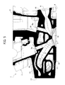
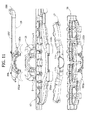
図1から図10を参照して、上面3を有する一つのアルミニウム本体2、下面4(図2を参照)、第1端面5、及び第2端面6を有する本発明によるシリンダヘッドがその全体を符号1で示されている。
1 to 10, a cylinder head according to the present invention having one
エンジン・シリンダに関連する燃焼室を形成するキャビティ7(図4及び5を参照)は、シリンダヘッドの下面4において形成されている。図示する実施例は、各エンジン・シリンダにつき2つの吸気弁及び2つの排気弁を設けたエンジンの場合を示す。よって、各エンジン・シリンダに関して、2つの吸気管8と2つの排気管9(図5及び図6を参照)が、シリンダヘッド1の本体2において鋳造によって形成される。吸気管8は、ヘッドの長手方向の側面10で終端する(図3、図5、図6を参照)。図5及び図10は、また、上部にてヘッドの上面3で終端し、下部にてそれぞれの吸気管8及び排気管9で終端して、吸気弁及び排気弁のステムを受け入れガイドする貫通穴8a,9aを示している。1つ以上のカムシャフト、並びに、吸気及び排気弁の動作用のそれぞれのタペットを収容するキャビティ11(図1及び図3)は、従来の技術によるヘッドの上面に設けられている。
A cavity 7 (see FIGS. 4 and 5) forming a combustion chamber associated with the engine cylinder is formed in the
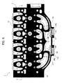
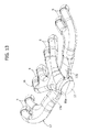
図5、図6及び図7において明らかに判るように、エンジン排気マニホールドもシリンダヘッド1において単一の鋳造片にて提供される。排気マニホールドを形成する導管の全体構成は、添付図の図13において明らかであり、それらを得るために用いられる砂型鋳造のコアの構成に対応する。かかる図において、シリンダヘッドにて得られたキャビティに対応する中子砂の部分は、同じ参照符号で示される。
As can be clearly seen in FIGS. 5, 6 and 7, the engine exhaust manifold is also provided in the
図13において判るように、すべての排気管9は、ターボチャージャー・ユニット(不図示)を取り付けるための平坦面14にてスクリューの係合用の軸受孔15にて、シリンダヘッド(図1)の長手方向の側面13で終端する共通の出口12に合流する。図13において、排気マニホールドを形成する排気管9は、それぞれ参照符号16、17で示された、排気管の2つの別々のサブグループを形成する。サブグループ16は、一連に整列した4つのシリンダーの中心にある2つのエンジン・シリンダにつながる排気管9によって構成され、サブグループ17は、一連のシリンダーの両端にある2つのシリンダーにつながる排気管9によって構成されている。第1サブグループ16の排気管9は、端のシリンダーの各々の排気管9が合流するサブグループ17の2つの導管17a部分とともに、出口12にて順にまとめられるマニホールド16aの一部に相互に合流する。導管17aは、シリンダヘッドに関して、その一方が他方に向かって、共通の出口12内で部分16aによってそれらが合流するマニホールドの中央部分まで、略長手方向に延在する。
As can be seen in FIG. 13, all the
図1にてわかるように、図示する実施例の場合では、排気マニホールドが統合されるシリンダヘッドの部分は、長手方向の側面13から突出する部分13aを形成する。
As can be seen in FIG. 1, in the illustrated embodiment, the portion of the cylinder head into which the exhaust manifold is integrated forms a
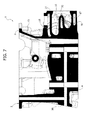
特に図4及び図5を参照して、ヘッド及び特にヘッドに設けられた排気マニホールドを冷却するために、下部冷却ジャケット18、上部冷却ジャケット19、及び中間冷却ジャケット20もまた、シリンダヘッド1の本体において鋳造することによって形成される。下部冷却ジャケット18及び上部冷却ジャケット19は、中央の共通出口12のまわりに、また、排気マニホールドを形成する導管の略上方及び下方に延在する。中間ジャケット20は、排気管16、17のサブグループの各中央部、これらは重なりかつ互いに離れて配置される、の間で延在し、一部分及び他部分からヘッドの反対側端まで延在する。3つのジャケット18、19、20の構成は、図11から図17に図示される、対応の中子砂の構成を見ることで明らかである。図11から図17では、中子砂の各部分は、それらに対応する、ヘッド1のキャビティを示すのと同じ参照符号を用いて示されている。
With particular reference to FIGS. 4 and 5, a
図において、参照符号21は、種々のエンジン・シリンダに関連する点火プラグを取り付けるためのシリンダヘッドに設けられる導管を示し、参照符号22は、種々のシリンダーに関連するインジェクターを取り付けることを可能にするためにヘッドに設けられる更なる導管を示している。
In the figure,
図8及び図9は、図4のVIII−VIII部、及びIX−IX部における断面図であり、下部冷却ジャケット18を示す。図6は、図2のVI−VI部に対応する水平面におけるヘッドの断面図であり、中間冷却ジャケット20を示す。図10は、図4のX−X部による断面図であり、上部冷却ジャケット19を示す。
8 and 9 are cross-sectional views taken along lines VIII-VIII and IX-IX in FIG. 4 and show the
図14も図8及び図9も参照して、下部冷却ジャケット18が、シリンダヘッドを有する単一の鋳造片に設けられる横仕切板181によって、4つのエンジン・シリンダに関連する4つの横チャンバ180へ長手方向において分割されるということが明らかにわかる。シリンダヘッドの全長にわたり分配され、かつ燃焼室7の吸気側及び排気側にそれぞれ隣接するヘッドの下面から始まって設けられる導管182によって、下部冷却ジャケット18の横チャンバ180は、エンジンブロックに設けられる循環路から冷却液を受け入れるように設計される。図14は、エンジンブロックに設けられた循環路から来る、図4及び図14にて矢印183で示される冷却液の、下部冷却ジャケット18の別個の横チャンバ180における、到着を可能にする上述の連通管のいくつかを得るために使用される中子砂の付属物182を示す。
Referring to FIGS. 14 and 8 and 9 as well, four
チャンバ180は、ヘッドの排気側に沿って延在し、上記下部ジャケット18の長手方向の連続的な部分185で終端する(図14も参照)。
The
上述した配置により、エンジンブロックから来る冷却液は、ヘッドの長手方向に直角の方向に従い、下部冷却ジャケット18を通り4つの横チャンバ180を、平行に、強制的に通過させられる。したがって、横チャンバ180を通過する冷却液は、排気管のサブグループ17の下を通過してサブグループ17の壁を冷やしながらシリンダヘッドの排気側に達する。
With the arrangement described above, the coolant coming from the engine block is forced through the four
冷却液は、燃焼室に隣接して配置される導管184(図14)、及び、排気ガス用の中央出口12の2つの側部にてシリンダヘッドの面13上で終端する2つの円筒状のキャビティ192を塞ぐ閉エレメント191によって形成された1対の導管190(図4)の両方によって、下部冷却ジャケット18から上部冷却ジャケット19まで通過する(図1、4、6、14、15を参照)。図1及び図2において、閉エレメント191は省略されており、よって、下部冷却ジャケット18と中間冷却ジャケット20とを分離する隔壁189(図4)の端を示すことができている。図4にて明らかにわかるように、閉エレメント191は、連通管190を形成するように、隔壁189の先端から離れて配置されている。
The coolant is in the form of two cylindrical ends that terminate on the
図4において明らかにわかるように、導管190の各々は、中間ジャケット20と下部ジャケット18を連通するだけでなく、上部ジャケット19と両方のジャケット18,20をまた連通する場所を形成する。したがって、それぞれの導管190は、3つのジャケット間の相互接続のための導管である。
As can be clearly seen in FIG. 4, each of the
図11及び図12において、参照符号18は、本発明によるシリンダヘッドの下部冷却ジャケット18を形成するよう設計された中子砂を、全体として示しており、参照符号19及び20は、上部冷却ジャケット19及び中間冷却ジャケット20を形成するよう設計された中子砂を示している。上述の管状の付属物192によって形成された円筒状のキャビティは、それら3つの砂型鋳造のコアの付属物192a間の協働の結果として得られる。
11 and 12,
このような配置により、発明によるシリンダヘッドでは、下部冷却ジャケット18から来る冷却液は、下部ジャケット18の別々のチャンバ180とそれぞれ連通する上述の導管190及び導管184を通って上部冷却ジャケット19に到達する。この冷却液は、図14の矢印(F)の方向において下部ジャケット18から出て、導管190を通って上部ジャケット19にも直接に、また中間ジャケット20にも入る。
With such an arrangement, in the cylinder head according to the invention, the coolant coming from the
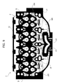
図15を参照して、中間ジャケット20は、ヘッドの全てにわたり長手方向に延在し、ヘッドの端にて、下部ジャケット18及び中間ジャケット20を通過した冷却液がヘッドから通って出るところのメイン出口201で終端する。
Referring to FIG. 15, the
図16を参照して、上部冷却ジャケット19は、排気マニホールドの上部16の上方でヘッドの中央にて第1部分196を有し、また、第1部分196から、メイン出口201に隣接して補助循環路198を形成するところのヘッドの端まで長手方向に延在する第2部分197を有する。第1部分196は、ガスの出口領域を、上部で、囲むブリッジ部を含んでいる。第2部分197は、ジャケット19の上部の部分に蓄積する気泡の放出を可能にするのに有用な経路を形成する。
Referring to FIG. 16, the
上述の説明から明らかなように、発明によるシリンダヘッドは、そこに統合された排気マニホールドを有し、また、重なり互いに離れて配置されるマニホールド部に合流する排気管の別々のサブグループ16、17を備える。さらに、ヘッドの全長手寸法にわたり分配された複数の開口を通してエンジンブロックから冷却液を受け入れる下部冷却ジャケットは、冷却液がヘッドの長手方向に交差して平行に通過する複数の別々の横チャンバ180へ冷却液を供給するように設けられる。よって冷却液は、下部冷却ジャケットから上部及び中間冷却ジャケットまで通過する。中間冷却ジャケットでは、冷却液がシリンダヘッドの端で出口201、198にて冷却液の出口まで横に及び長手方向の両方に通過される。
As is clear from the above description, the cylinder head according to the invention has an exhaust manifold integrated therein, and
発明によるシリンダヘッドは、上述の特徴によって、重なり間隔をあけられた排気管のサブグループによって形成された排気マニホールドの利点を、複数の冷却ジャケットの特定の構成及び配置から引き出したより効率的な冷却に関する利点と組み合わせることを可能にする。同時に、発明によるシリンダヘッドは、上述したように構成された砂型鋳造のコアの提供によって、比較的簡単な方法で及び比較的低コストで得ることができる。 The cylinder head according to the invention relates to more efficient cooling, which, by virtue of the features described above, draws the advantages of the exhaust manifold formed by the sub-groups of the exhaust pipes spaced apart from each other from a specific configuration and arrangement of a plurality of cooling jackets. Allows to combine with benefits. At the same time, the cylinder head according to the invention can be obtained in a relatively simple manner and at a relatively low cost by providing a sand-cast core configured as described above.
言うまでもなく、発明の原理をそこなうことなく、構造詳細及び実施態様は、本発明の保護の範囲から逸脱せずに、純粋に実施例の目的で記述され説明されたものに対して広く変更可能である。 Of course, without departing from the principles of the invention, the structural details and embodiments may be varied widely from what has been described and illustrated purely for the purposes of example, without departing from the scope of protection of the present invention. is there.
Claims (1)
− 上面(3)、下面(4)、2つの端面(5、6)、及び2つの側面(10、13)を有する本体(2)を有し、
− 上記本体は、一つの鋳造片においてエンジン排気マニホールド(16、17)を一体化し、
− 上記排気マニホールド(16、17)は、ヘッド(1)の本体(2)に設けられた排気ガス用の複数の導管(9)によって形成され、重なり互いに離れて配置されヘッドの横面(13,14)に終端するマニホールド部(16a、17a)に合流する排気管の別々のサブグループ(16と17)を形成し、
− ヘッド(1)の本体(2)内で、排気マニホールド(16、17)を形成する導管(9)のほぼ下方及び上方に設けられる下部冷却ジャケット(18)及び上部冷却ジャケット(19)と、重なり互いに離れて配置される上記排気マニホールド(16、17)の間に配置される中間冷却ジャケット(20)とを有し、
− 上記中間冷却ジャケット(20)は、排気マニホールドの出口領域の2つの側部にて、上記側面(13、14)に隣接して配列される2つの相互接続管を通して下部及び上部のジャケット(18、19)と連通される、内燃機関用のシリンダヘッド(1)において、
− 上記排気マニホールドの導管(9)は、ヘッド(1)の上記側面(13、14)で終端する共通の出口(12)へ合流し、
− 下部冷却ジャケット(18)は、様々なエンジン・シリンダに関連する複数の別々の横チャンバ(180)へ長手方向において分割され、ヘッドの排気側に沿って延在した、上記下部冷却ジャケットの長手方向の連続部分で終端し、
− 中間冷却ジャケット(20)は、ヘッドの長手方向の全伸長にわたり延在し、ヘッド(1)から冷却液が出ることに関して、下部冷却ジャケット(18)の上記チャンバと連通する導管(184)と、ヘッド(1)の一端(6)に出口(201)とを有し、
− 上部冷却ジャケット(19)は、排気マニホールドの上部(16)の上方でヘッドの中央に第1部分(196)を有し、この第1部分(196)から、上記出口(201)に隣接して補助循環路(198)を形成する、ヘッド(1)の上記一端(6)まで長手方向に延在する第2部分(197)を有する、
ことを特徴とする内燃機関用のシリンダヘッド。 A cylinder head (1) for an internal combustion engine,
A body (2) having an upper surface (3), a lower surface (4), two end surfaces (5, 6), and two side surfaces (10, 13);
The body integrates the engine exhaust manifold (16, 17) in one cast piece;
The exhaust manifold (16, 17) is formed by a plurality of exhaust gas conduits (9) provided in the main body (2) of the head (1), and is arranged so as to be spaced apart from each other and to the lateral surface of the head (13 , 14) to form separate subgroups (16 and 17) of exhaust pipes joining the manifold sections (16a, 17a),
A lower cooling jacket (18) and an upper cooling jacket (19) provided in the main body (2) of the head (1) substantially below and above the conduit (9) forming the exhaust manifold (16, 17); An intermediate cooling jacket (20) disposed between the exhaust manifolds (16, 17) disposed overlapping and spaced apart from each other;
The intermediate cooling jacket (20) is connected to the lower and upper jackets (18) through two interconnecting tubes arranged adjacent to the side surfaces (13, 14) at two sides of the outlet area of the exhaust manifold. , 19) in a cylinder head (1) for an internal combustion engine,
The exhaust manifold conduit (9) merges into a common outlet (12) terminating at the side (13, 14) of the head (1);
The lower cooling jacket (18) is longitudinally divided into a plurality of separate transverse chambers (180) associated with the various engine cylinders and extends along the exhaust side of the head, the length of the lower cooling jacket Terminate in a continuous part of direction,
The intermediate cooling jacket (20) extends over the entire longitudinal extension of the head and is connected with a conduit (184) in communication with the chamber of the lower cooling jacket (18) with respect to the exit of the cooling liquid from the head (1). And an outlet (201) at one end (6) of the head (1),
The upper cooling jacket (19) has a first part (196) in the center of the head above the upper part (16) of the exhaust manifold, from which the first part (196) is adjacent to the outlet (201); A second portion (197) extending longitudinally to the one end (6) of the head (1), forming an auxiliary circuit (198)
A cylinder head for an internal combustion engine.
Applications Claiming Priority (2)
| Application Number | Priority Date | Filing Date | Title |
|---|---|---|---|
| EP11157678.1A EP2500558B1 (en) | 2011-03-10 | 2011-03-10 | Cylinder head for an internal combustion engine, with integrated exhaust manifold and subgroups of exhaust conduits merging into manifold portions which are superimposed and spaced apart from each other |
| EP11157678.1 | 2011-03-10 |
Publications (2)
| Publication Number | Publication Date |
|---|---|
| JP2012189075A true JP2012189075A (en) | 2012-10-04 |
| JP5684699B2 JP5684699B2 (en) | 2015-03-18 |
Family
ID=44351750
Family Applications (1)
| Application Number | Title | Priority Date | Filing Date |
|---|---|---|---|
| JP2011283907A Active JP5684699B2 (en) | 2011-03-10 | 2011-12-26 | Cylinder head for an internal combustion engine having an integrated exhaust manifold and subgroup of exhaust pipes that merge into manifold parts that are arranged apart from each other |
Country Status (4)
| Country | Link |
|---|---|
| US (1) | US8671904B2 (en) |
| EP (1) | EP2500558B1 (en) |
| JP (1) | JP5684699B2 (en) |
| BR (1) | BRPI1107007B1 (en) |
Cited By (4)
| Publication number | Priority date | Publication date | Assignee | Title |
|---|---|---|---|---|
| JP2012189076A (en) * | 2011-03-10 | 2012-10-04 | Fiat Powertrain Technologies Spa | Cylinder head for internal combustion engine, with integrated exhaust manifold and subgroups of exhaust conduits merging into manifold portions which are superimposed and spaced apart from each other |
| JP2015059492A (en) * | 2013-09-18 | 2015-03-30 | トヨタ自動車株式会社 | Cylinder head |
| JP2016121541A (en) * | 2014-12-24 | 2016-07-07 | 本田技研工業株式会社 | Cooling structure for internal combustion engine |
| JP2020509290A (en) * | 2017-03-01 | 2020-03-26 | アー・ファウ・エル・リスト・ゲー・エム・ベー・ハーAvl List Gmbh | Cylinder head of internal combustion engine |
Families Citing this family (19)
| Publication number | Priority date | Publication date | Assignee | Title |
|---|---|---|---|---|
| USD731556S1 (en) * | 2012-09-14 | 2015-06-09 | Honda Motor Co., Ltd. | Cylinder head for internal combustion engines |
| DE102013221231B4 (en) * | 2012-10-19 | 2014-12-24 | Honda Motor Co., Ltd. | Water jacket structure for a cylinder head |
| JP5729367B2 (en) * | 2012-10-25 | 2015-06-03 | トヨタ自動車株式会社 | Cylinder head cooling structure |
| JP5864401B2 (en) * | 2012-11-09 | 2016-02-17 | 本田技研工業株式会社 | Water jacket structure of internal combustion engine |
| CN103291487B (en) * | 2013-05-27 | 2015-06-03 | 安徽江淮汽车股份有限公司 | Cooling water system for cylinder heads of engine |
| US9732662B2 (en) * | 2013-06-14 | 2017-08-15 | GM Global Technology Operations LLC | Coolant control systems and methods for transmission temperature regulation |
| US9133745B2 (en) * | 2013-08-30 | 2015-09-15 | GM Global Technology Operations LLC | Split/dual plane integrated exhaust manifold for dual scroll turbo charger |
| US9188051B1 (en) * | 2014-06-24 | 2015-11-17 | GM Global Technology Operations LLC | System and method of thermal management for an engine |
| JP6131920B2 (en) | 2014-07-28 | 2017-05-24 | トヨタ自動車株式会社 | Internal combustion engine cooling structure |
| GB2536030A (en) * | 2015-03-04 | 2016-09-07 | Gm Global Tech Operations Llc | A water jacket for an internal combustion engine |
| DE102015222859A1 (en) * | 2015-11-19 | 2017-05-24 | ŠKODA AUTO a.s. | Cylinder head of an internal combustion engine with integrated exhaust manifold and cooling jacket |
| JP6747029B2 (en) * | 2016-04-14 | 2020-08-26 | 三菱自動車工業株式会社 | Engine cylinder head |
| CN106089470B (en) * | 2016-07-29 | 2018-09-11 | 重庆长安汽车股份有限公司 | A kind of engine cool nested structure of integrated exhaust manifold |
| CN106224079A (en) * | 2016-09-30 | 2016-12-14 | 奇瑞汽车股份有限公司 | A kind of cylinder cover of automobile engine |
| AT520322B1 (en) * | 2017-08-21 | 2019-03-15 | Avl List Gmbh | CYLINDER HEAD |
| US10801380B1 (en) * | 2017-11-29 | 2020-10-13 | Steve Sousley | Durable high performance water-cooled exhaust systems and components and methods of manufacture |
| US11441474B2 (en) * | 2020-11-18 | 2022-09-13 | Ford Global Technologies, Llc | Integrated exhaust manifold cooling jacket |
| CN114991983A (en) * | 2021-03-01 | 2022-09-02 | 比亚迪股份有限公司 | Engine and vehicle |
| US11300072B1 (en) * | 2021-05-12 | 2022-04-12 | Ford Global Technologies, Llc | Cylinder head for an internal combustion engine |
Citations (6)
| Publication number | Priority date | Publication date | Assignee | Title |
|---|---|---|---|---|
| JP2006083756A (en) * | 2004-09-15 | 2006-03-30 | Daihatsu Motor Co Ltd | Structure of cylinder head in multi-cylinder internal combustion engine |
| JP2006329128A (en) * | 2005-05-27 | 2006-12-07 | Toyota Motor Corp | Cooling structure of internal combustion engine |
| JP2007285168A (en) * | 2006-04-14 | 2007-11-01 | Toyota Motor Corp | Cylinder head structure of internal combustion engine |
| US20090241526A1 (en) * | 2008-04-01 | 2009-10-01 | Hyundai Motor Company | Exhaust Manifold Being Integrally Formed with Cylinder Head |
| US20100083920A1 (en) * | 2008-10-02 | 2010-04-08 | Ford Global Technologies, Llc | Cylinder head for an internal combustion engine |
| JP2010209712A (en) * | 2009-03-07 | 2010-09-24 | Toyota Motor Corp | Engine exhaust manifold |
Family Cites Families (7)
| Publication number | Priority date | Publication date | Assignee | Title |
|---|---|---|---|---|
| DE2508952C2 (en) | 1975-03-01 | 1982-12-23 | Daimler-Benz Ag, 7000 Stuttgart | Cylinder housing for a multi-cylinder four-stroke internal combustion engine |
| JP2709815B2 (en) * | 1988-01-11 | 1998-02-04 | ヤマハ発動機株式会社 | Cylinder head structure of turbocharged engine |
| US6788540B2 (en) * | 2002-01-30 | 2004-09-07 | Jds Uniphase Corporation | Optical transceiver cage |
| JP4463210B2 (en) * | 2006-01-13 | 2010-05-19 | 本田技研工業株式会社 | Multi-cylinder internal combustion engine having a cylinder head formed with a collective exhaust port |
| EP2003320B1 (en) * | 2007-06-13 | 2017-10-11 | Ford Global Technologies, LLC | Cylinder head for an internal combustion engine |
| US7784442B2 (en) * | 2007-11-19 | 2010-08-31 | Gm Global Technology Operations, Inc. | Turbocharged engine cylinder head internal cooling |
| US8474251B2 (en) * | 2010-10-19 | 2013-07-02 | Ford Global Technologies, Llc | Cylinder head cooling system |
-
2011
- 2011-03-10 EP EP11157678.1A patent/EP2500558B1/en active Active
- 2011-11-28 US US13/305,460 patent/US8671904B2/en active Active
- 2011-12-01 BR BRPI1107007-2A patent/BRPI1107007B1/en active IP Right Grant
- 2011-12-26 JP JP2011283907A patent/JP5684699B2/en active Active
Patent Citations (6)
| Publication number | Priority date | Publication date | Assignee | Title |
|---|---|---|---|---|
| JP2006083756A (en) * | 2004-09-15 | 2006-03-30 | Daihatsu Motor Co Ltd | Structure of cylinder head in multi-cylinder internal combustion engine |
| JP2006329128A (en) * | 2005-05-27 | 2006-12-07 | Toyota Motor Corp | Cooling structure of internal combustion engine |
| JP2007285168A (en) * | 2006-04-14 | 2007-11-01 | Toyota Motor Corp | Cylinder head structure of internal combustion engine |
| US20090241526A1 (en) * | 2008-04-01 | 2009-10-01 | Hyundai Motor Company | Exhaust Manifold Being Integrally Formed with Cylinder Head |
| US20100083920A1 (en) * | 2008-10-02 | 2010-04-08 | Ford Global Technologies, Llc | Cylinder head for an internal combustion engine |
| JP2010209712A (en) * | 2009-03-07 | 2010-09-24 | Toyota Motor Corp | Engine exhaust manifold |
Cited By (6)
| Publication number | Priority date | Publication date | Assignee | Title |
|---|---|---|---|---|
| JP2012189076A (en) * | 2011-03-10 | 2012-10-04 | Fiat Powertrain Technologies Spa | Cylinder head for internal combustion engine, with integrated exhaust manifold and subgroups of exhaust conduits merging into manifold portions which are superimposed and spaced apart from each other |
| JP2015059492A (en) * | 2013-09-18 | 2015-03-30 | トヨタ自動車株式会社 | Cylinder head |
| JP2016121541A (en) * | 2014-12-24 | 2016-07-07 | 本田技研工業株式会社 | Cooling structure for internal combustion engine |
| US10107171B2 (en) | 2014-12-24 | 2018-10-23 | Honda Motor Co., Ltd. | Cooling structure of internal combustion engine |
| JP2020509290A (en) * | 2017-03-01 | 2020-03-26 | アー・ファウ・エル・リスト・ゲー・エム・ベー・ハーAvl List Gmbh | Cylinder head of internal combustion engine |
| JP7100051B2 (en) | 2017-03-01 | 2022-07-12 | アー・ファウ・エル・リスト・ゲー・エム・ベー・ハー | Internal combustion engine cylinder head |
Also Published As
| Publication number | Publication date |
|---|---|
| US20120227686A1 (en) | 2012-09-13 |
| US8671904B2 (en) | 2014-03-18 |
| BRPI1107007B1 (en) | 2021-01-12 |
| EP2500558A1 (en) | 2012-09-19 |
| BRPI1107007A2 (en) | 2013-06-11 |
| JP5684699B2 (en) | 2015-03-18 |
| EP2500558B1 (en) | 2017-02-15 |
Similar Documents
| Publication | Publication Date | Title |
|---|---|---|
| JP5684699B2 (en) | Cylinder head for an internal combustion engine having an integrated exhaust manifold and subgroup of exhaust pipes that merge into manifold parts that are arranged apart from each other | |
| JP5631859B2 (en) | Cylinder head for an internal combustion engine having an integrated exhaust manifold and a subgroup of exhaust conduits that merge into overlapping and spaced manifold portions | |
| US10107171B2 (en) | Cooling structure of internal combustion engine | |
| JP5864401B2 (en) | Water jacket structure of internal combustion engine | |
| EP2049784A2 (en) | Internal combustion engine | |
| US20110277723A1 (en) | Cylinder head for an internal combustion engine, with integrated exhaust manifold | |
| US20120132155A1 (en) | Cylinder head having plural water jackets and cast-in water rail | |
| JP2016173107A (en) | Cylinder head for internal combustion engine having cooling channel | |
| JP2014084740A (en) | Water jacket structure of cylinder head | |
| JP5278299B2 (en) | Cylinder head cooling structure | |
| JP2010265840A (en) | Cylinder head water jacket structure | |
| JP5711715B2 (en) | Cylinder head coolant passage structure | |
| JP5587380B2 (en) | Cylinder head water jacket structure | |
| TWI672436B (en) | Cylinder head | |
| JP2009180109A (en) | Cooling structure of exhaust manifold integrated cylinder head | |
| JP6696125B2 (en) | Cylinder head cooling structure | |
| JP2009275575A (en) | Cooling device for internal combustion engine | |
| EP0984149B1 (en) | Cylinder head structure in internal combustion engine | |
| JP2022145262A (en) | Multicylinder internal combustion engine | |
| JP2018131999A (en) | Cylinder head for engine | |
| BRPI1106151A2 (en) | CYLINDER HEAD FOR AN INTERNAL COMBUSTION ENGINE |
Legal Events
| Date | Code | Title | Description |
|---|---|---|---|
| A621 | Written request for application examination |
Free format text: JAPANESE INTERMEDIATE CODE: A621 Effective date: 20130311 |
|
| A131 | Notification of reasons for refusal |
Free format text: JAPANESE INTERMEDIATE CODE: A131 Effective date: 20140520 |
|
| A521 | Request for written amendment filed |
Free format text: JAPANESE INTERMEDIATE CODE: A523 Effective date: 20140701 |
|
| TRDD | Decision of grant or rejection written | ||
| A01 | Written decision to grant a patent or to grant a registration (utility model) |
Free format text: JAPANESE INTERMEDIATE CODE: A01 Effective date: 20141216 |
|
| A61 | First payment of annual fees (during grant procedure) |
Free format text: JAPANESE INTERMEDIATE CODE: A61 Effective date: 20150115 |
|
| R150 | Certificate of patent or registration of utility model |
Ref document number: 5684699 Country of ref document: JP Free format text: JAPANESE INTERMEDIATE CODE: R150 |
|
| R250 | Receipt of annual fees |
Free format text: JAPANESE INTERMEDIATE CODE: R250 |
|
| R250 | Receipt of annual fees |
Free format text: JAPANESE INTERMEDIATE CODE: R250 |
|
| R250 | Receipt of annual fees |
Free format text: JAPANESE INTERMEDIATE CODE: R250 |
|
| R250 | Receipt of annual fees |
Free format text: JAPANESE INTERMEDIATE CODE: R250 |
|
| R250 | Receipt of annual fees |
Free format text: JAPANESE INTERMEDIATE CODE: R250 |
|
| R250 | Receipt of annual fees |
Free format text: JAPANESE INTERMEDIATE CODE: R250 |
|
| R250 | Receipt of annual fees |
Free format text: JAPANESE INTERMEDIATE CODE: R250 |