JP2012187228A - Photographing apparatus and image processing method - Google Patents
Photographing apparatus and image processing method Download PDFInfo
- Publication number
- JP2012187228A JP2012187228A JP2011052287A JP2011052287A JP2012187228A JP 2012187228 A JP2012187228 A JP 2012187228A JP 2011052287 A JP2011052287 A JP 2011052287A JP 2011052287 A JP2011052287 A JP 2011052287A JP 2012187228 A JP2012187228 A JP 2012187228A
- Authority
- JP
- Japan
- Prior art keywords
- image
- tomographic image
- motion information
- fundus
- oct
- Prior art date
- Legal status (The legal status is an assumption and is not a legal conclusion. Google has not performed a legal analysis and makes no representation as to the accuracy of the status listed.)
- Granted
Links
Images


Classifications
-
- A—HUMAN NECESSITIES
- A61—MEDICAL OR VETERINARY SCIENCE; HYGIENE
- A61B—DIAGNOSIS; SURGERY; IDENTIFICATION
- A61B3/00—Apparatus for testing the eyes; Instruments for examining the eyes
- A61B3/10—Objective types, i.e. instruments for examining the eyes independent of the patients' perceptions or reactions
- A61B3/102—Objective types, i.e. instruments for examining the eyes independent of the patients' perceptions or reactions for optical coherence tomography [OCT]
-
- A—HUMAN NECESSITIES
- A61—MEDICAL OR VETERINARY SCIENCE; HYGIENE
- A61B—DIAGNOSIS; SURGERY; IDENTIFICATION
- A61B3/00—Apparatus for testing the eyes; Instruments for examining the eyes
- A61B3/10—Objective types, i.e. instruments for examining the eyes independent of the patients' perceptions or reactions
- A61B3/12—Objective types, i.e. instruments for examining the eyes independent of the patients' perceptions or reactions for looking at the eye fundus, e.g. ophthalmoscopes
-
- A—HUMAN NECESSITIES
- A61—MEDICAL OR VETERINARY SCIENCE; HYGIENE
- A61B—DIAGNOSIS; SURGERY; IDENTIFICATION
- A61B3/00—Apparatus for testing the eyes; Instruments for examining the eyes
- A61B3/10—Objective types, i.e. instruments for examining the eyes independent of the patients' perceptions or reactions
- A61B3/113—Objective types, i.e. instruments for examining the eyes independent of the patients' perceptions or reactions for determining or recording eye movement
-
- G—PHYSICS
- G06—COMPUTING; CALCULATING OR COUNTING
- G06T—IMAGE DATA PROCESSING OR GENERATION, IN GENERAL
- G06T7/00—Image analysis
- G06T7/20—Analysis of motion
- G06T7/246—Analysis of motion using feature-based methods, e.g. the tracking of corners or segments
- G06T7/251—Analysis of motion using feature-based methods, e.g. the tracking of corners or segments involving models
-
- G—PHYSICS
- G06—COMPUTING; CALCULATING OR COUNTING
- G06T—IMAGE DATA PROCESSING OR GENERATION, IN GENERAL
- G06T2207/00—Indexing scheme for image analysis or image enhancement
- G06T2207/10—Image acquisition modality
- G06T2207/10072—Tomographic images
- G06T2207/10101—Optical tomography; Optical coherence tomography [OCT]
-
- G—PHYSICS
- G06—COMPUTING; CALCULATING OR COUNTING
- G06T—IMAGE DATA PROCESSING OR GENERATION, IN GENERAL
- G06T2207/00—Indexing scheme for image analysis or image enhancement
- G06T2207/30—Subject of image; Context of image processing
- G06T2207/30004—Biomedical image processing
- G06T2207/30041—Eye; Retina; Ophthalmic
Abstract
Description
本発明は、撮像装置及び画像処理方法に関するものである。特に、眼球の動き情報を用い、眼底断層画像に眼球の動き情報を反映させた撮像装置及び画像処理方法に関するものである。 The present invention relates to an imaging apparatus and an image processing method. In particular, the present invention relates to an imaging apparatus and an image processing method that use eyeball motion information and reflect eyeball motion information in a fundus tomographic image.
近年、眼底断層画像が取得できるOCT(Optical Coherence Tomography)装置が注目されている。それは、他の装置では観察できない眼底の内部構造が非侵襲で診断できる事が要因の一つである。中でも、高速に撮像可能で実績のあるFD−OCT(Fourier Domain)が市場の中心である。OCT装置には眼底カメラやSLO(Scanning Laser Ophthalmoscope)が同一装置内に装備され、眼底のどのエリアをOCTスキャンするかを表示する事で、所望のエリアのOCT画像を取得することができる。 In recent years, an OCT (Optical Coherence Tomography) apparatus capable of acquiring a fundus tomographic image has attracted attention. One of the factors is that non-invasive diagnosis of the internal structure of the fundus that cannot be observed with other devices is possible. Among them, FD-OCT (Fourier Domain), which can be imaged at high speed and has a proven record, is the center of the market. The OCT apparatus is equipped with a fundus camera and SLO (Scanning Laser Ophthalmoscope) in the same apparatus, and an OCT image of a desired area can be acquired by displaying which area of the fundus is OCT scanned.
一方、早期診断、早期治療から微小の腫瘍や異常を検出する為、OCT画像の高画質化が求められている。高画質化を達成するためには、眼球の移動にOCTビームを追従する装置(特許文献)が公開されている。 On the other hand, in order to detect minute tumors and abnormalities from early diagnosis and early treatment, high image quality of OCT images is required. In order to achieve high image quality, an apparatus (patent document) that tracks the movement of the eyeball with an OCT beam is disclosed.
上述の公開特許文献では、OCT装置に眼球の移動を検出する為の装置を付加している。その装置は眼底の視神経乳頭を追尾し、リアルタイムでOCTスキャナを制御する事で、所望の個所のOCT画像を取得している。 In the above-mentioned published patent document, a device for detecting movement of the eyeball is added to the OCT device. The apparatus tracks the optic disc of the fundus and controls the OCT scanner in real time to acquire an OCT image at a desired location.
FD-OCTが高速化を実現した事により眼球の移動情報を取得する時間よりも、OCT画像を取得する時間の方が速くなる事がある。この様な装置においては、必ずしも全てのOCT画像に対応する位置情報が得られないという問題があった。 Since the speed of FD-OCT is increased, the time for acquiring the OCT image may be faster than the time for acquiring the movement information of the eyeball. Such an apparatus has a problem that position information corresponding to all OCT images cannot be obtained.
上述の公開特許文献の構成では、高速に追尾することが可能であるが、追尾用の装置を付加させる事が必須となり、装置の大型化、更には、追尾用のスキャナ等高価な部品が必要となる。 In the configuration of the above-mentioned published patent document, it is possible to track at high speed, but it is essential to add a tracking device, and the size of the device is increased, and furthermore, expensive components such as a tracking scanner are required. It becomes.
通常のOCT画像の取得レートより追尾画像の取得レートが遅い追尾装置を有するOCT装置においては、画像の重ね合わせを行うと、位置情報が存在しないOCT画像が存在し、且つ眼球特有のマイクロサッカードなどにより画像の重ね合わせの精度が悪い、という問題があった。 In an OCT apparatus having a tracking device whose tracking image acquisition rate is slower than the normal OCT image acquisition rate, when the images are superimposed, there is an OCT image without position information and a microsaccade peculiar to the eyeball. As a result, there is a problem that the accuracy of overlaying images is poor.
上記課題を解決するために、本発明に係る撮像装置は、被検眼の眼底画像を撮像する眼底画像撮像部と、前記被検眼の断層画像を撮像する断層画像撮像部と、前記被検眼の動き情報を、前記眼底画像から算出する算出手段と、前記算出した動き情報と前記断層画像とを対応付ける対応付け手段と、を有し、前記算出手段は、前記対応付け手段による前記動き情報の対応付けが行われなかった前記断層画像の動き情報を、前記対応付けが行われなかった前記断層画像に時間的に近接し且つ動き情報が対応付けられた断層画像の動き情報に基づいて算出することを特徴とする。 In order to solve the above problems, an imaging apparatus according to the present invention includes a fundus image capturing unit that captures a fundus image of a subject eye, a tomographic image capturing unit that captures a tomographic image of the subject eye, and a movement of the subject eye. Calculation means for calculating information from the fundus image, and association means for associating the calculated motion information with the tomographic image, wherein the calculation means associates the motion information with the association means. Calculating the motion information of the tomographic image that has not been performed based on the motion information of the tomographic image that is temporally close to the tomographic image that has not been associated and associated with the motion information. Features.
また、上記課題を解決するために、本発明に係る画像処理方法は、被検眼の眼底画像と断層画像とを撮像し、前記眼底画像から前記被検眼の動き情報を算出し、前記算出した動き情報と前記断層画像とを対応付け、前記対応付けが行われなかった断層画像の動き情報を、前記対応付けが行われなかった断層画像に時間的に近接し且つ動き情報が対応付けられた断層画像の動き情報に基づいて算出することを特徴とする。 In order to solve the above problem, an image processing method according to the present invention captures a fundus image and a tomographic image of a subject eye, calculates motion information of the subject eye from the fundus image, and calculates the calculated motion. Information and the tomographic image are associated, and the motion information of the tomographic image that has not been correlated is temporally close to the tomographic image that has not been correlated and the tomographic image is associated with motion information The calculation is based on motion information of the image.
本発明によれば、眼底画像から被検眼の動き情報が取得できない場合においても、眼球の動き情報を算出することができ、適切な画像処理を行うことが可能となる。 According to the present invention, even when the movement information of the eye to be examined cannot be acquired from the fundus image, the movement information of the eyeball can be calculated, and appropriate image processing can be performed.
[実施例1]
以下、本発明の実施例1について説明する。
本実施例では、内部固視灯を有し、眼底画像の取得にSLOを用い、SLOで取得したSLO画像から眼球の移動量を求め、結果をOCT装置で取得するOCT画像の処理に反映する事で高画質なOCT画像の重ね合わせ画像(例えば、複数枚のOCT画像を平均化した画像)を取得する場合について述べる。
[Example 1]
In this embodiment, an internal fixation lamp is used, SLO is used to acquire the fundus image, the amount of movement of the eyeball is obtained from the SLO image acquired by the SLO, and the result is reflected in the processing of the OCT image acquired by the OCT apparatus. A case where a superposed image of high-quality OCT images (for example, an image obtained by averaging a plurality of OCT images) is acquired will be described.
(OCT撮像部の構成)
図1は、本実施例における撮像装置の光学系構成の概略図である。
まず、本発明における断層画像撮像部であるOCT撮像部の光学系構成に関して、図1を用いて説明する。
(Configuration of OCT imaging unit)
FIG. 1 is a schematic diagram of an optical system configuration of an imaging apparatus according to the present embodiment.
First, an optical system configuration of an OCT imaging unit which is a tomographic imaging unit in the present invention will be described with reference to FIG.
光源として、低コヒーレント光源101を用いる。光源101はSLD光源(Super Luminescent Diode)や、ASE光源(Amplified Spontaneous Emission)を好適に用いることができる。低コヒーレント光としては、850nm近傍および1050nm近傍の波長が眼底撮影には好適に用いられる。本実施例では、中心波長840nm、波長半値幅45nmのSLD光源を用いる。低コヒーレント光源101から出射される低コヒーレント光は、光ファイバを経由して、ファイバカプラ102に入り、サンプル光(OCTビーム)と参照光とに分けられる。ここではファイバを用いた干渉計構成を記載しているが、空間光光学系でビームスプリッタを用いた構成としてもかまわない。
A low
サンプル光は、ファイバ103を介して、ファイバコリメータ104から平行光となって出射される。出射されたサンプル光は、OCTスキャナ(Y)105、リレーレンズ106、107を経由し、さらにOCTスキャナ(X)108を通り、ダイクロイックビームスプリッタ109を透過しスキャンレンズ110、ダイクロイックミラー111、そして、接眼レンズ112を通り被検眼eを照射する。ここで、OCTスキャナ(X)108および(Y)105は、ガルバノスキャナを用いている。被検眼eにおけるサンプル光は、網膜で反射し、同一光路を通りファイバカプラ102に戻る。
The sample light is emitted as parallel light from the
参照光は、ファイバカプラ102からファイバコリメータ113に導かれ、平行光となり出射される。出射された参照光は、分散補正ガラス114を通り、光路長可変ステージ115上の参照ミラー116により反射される。参照ミラー116により反射された参照光は、同一の光路をたどり、ファイバカプラ102に戻る。
The reference light is guided from the
ファイバカプラ102で、戻ってきたサンプル光および参照光が合波され、ファイバコリメータ117に導かれる。ここでは合波された光を干渉光と呼ぶ。ファイバコリメータ117、グレーティング118、レンズ119、ラインセンサ120によって、分光器が構成されている。干渉光は、分光器によって、波長毎の強度情報となって計測される。ラインセンサ120によって計測された波長毎の強度情報は、後述するCPU201に転送され、被検眼eの断層画像として生成される。
The returned sample light and reference light are combined by the
(SLO撮像部の構成)
次に、眼底画像を取得する、本発明の眼底画像撮像部であるSLO撮像部の光学系構成に関して、同じく図1を用いて説明する。
(Configuration of SLO imaging unit)
Next, the optical system configuration of the SLO imaging unit, which is a fundus image imaging unit of the present invention, for acquiring a fundus image will be described with reference to FIG.
レーザ光源130は、半導体レーザやSLD光源が好適に用いることができる。用いる波長は、OCT用の低コヒーレント光源101の波長とダイクロイックビームスプリッタ109によって、使用波長同士が分離できる光源であれば制約はないが、眼底画像の画質として良好な、700nm〜1000nmの近赤外の波長域が好適に用いられる。本実施例においては、波長760nmの半導体レーザを用いる。レーザ光源130から出射されたレーザビーム(SLOビーム)はファイバ131を介して、ファイバコリメータ132から平行光となって出射され、穴空きミラー133、レンズ134を介し、SLOスキャナ(Y)135に導かれる。レンズ136、137を介し、SLOスキャナ(X)138を通過し、ダイクロイックビームスプリッタ109で反射され、ターゲットの被検眼eに入射する。ダイクロイックビームスプリッタ109は、OCTビームを透過し、SLOビームを反射するように構成しておく。OCT撮像部と同様、SLO撮像部のスキャナはガルバノスキャナを用いている。被検眼eに入射したSLOビームは、被検眼eの眼底に、ビームで照射される。このビームが、被検眼eの眼底で反射あるいは散乱され、同一光路をたどり、リングミラー133まで戻る。リングミラー133の位置は、被検眼eの瞳孔位置と共役になっており、眼底に照射されているビームが後方散乱した光のうち、瞳孔周辺部を通った光が、リングミラー133によって反射され、レンズ139によりAPD(アバランシェホトダイオード)140上に結像する。APD140の強度情報に基づき,後述するCPU201により眼底の平面画像を生成する。本実施例では、眼底にあるスポット径のビームを照射しスキャンする事で眼底画像を得るSLOを用いたが、ラインビームを用いるLSLO(Line SLO)構成であっても構わない。
As the
(内部固視灯)
本実施例では、固視微動を安定させる為、被検眼eに注視させる内部固視灯を有している。OCT撮像部、SLO撮像部同様、図1を用い説明する。
(Internal fixation light)
In the present embodiment, an internal fixation lamp for gazing at the eye to be examined e is provided in order to stabilize fixation fine movement. Similar to the OCT imaging unit and the SLO imaging unit, description will be made with reference to FIG.
固視灯に用いる光源150は発光ダイオード(LD)を用いる。発光ダイオードの点灯位置を、後述するCPU201の制御により撮像したい部位に合わせて変更する。発光ダイオード150は500nmの波長で、光源から出射されたビームは、レンズ151とダイクロイックミラー111を経由し、被検眼eに照射される。ダイクロイックミラー111は、スキャンレンズ110と接眼レンズ112の間に位置し、短波長(500nm程度)の光とOCTビーム,SLOビーム(700nm以上)を波長分離する。
The light source 150 used for the fixation lamp uses a light emitting diode (LD). The lighting position of the light emitting diode is changed in accordance with a part to be imaged under the control of the
(ユニット構成)
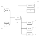
図2に本実施例で用いられる機能体系を示す。その機能体系は、装置全体を制御するCPU201と、SLO撮像部、OCT撮像部を制御する各々の制御部202、203、固視灯208、SLO画像及びOCT画像を取得する各々のAPD204(140)、ラインセンサ205(120)、システム状態や撮像した画像等を表示する表示部206、眼底画像や撮像条件等を記録する記録部207、により構成されている。眼底の撮像時には、固視灯208を制御し、所望の眼底エリアが撮像できるように固視灯を注視させ、CPU201より制御部202、203に各々の撮像条件が指令され、各々のスキャナを駆動し、眼底が撮像される。眼底が撮像された後、APD204、カメラ装置205からCPU201に画像が送られ、画像処理された後、表示部206で表示され、同時又はその後、記録部207に保存される。
(Unit configuration)
FIG. 2 shows a functional system used in this embodiment. The functional system includes a
(眼球運動)
眼球の眼底平面方向の移動量を計測すると、図3のような実線で示す動きが検出される。この計測中、被験者の注視領域は点線の307周辺である様に固視灯を制御している。一般的に、動きは以下のように分類される。高速な直線状の動きであるマイクロサッカード301、306、ややゆっくりとした動きのドリフト302、304、そして、ドリフトしている際に高速で微小振動するトレモア303、305に大別できる。この運動の移動速度、頻度は各個人に依存するが、マイクロサッカードは3mm/sec程度とも言われ、100μm/sec程度のドリフトとは桁違いの速さである。マイクロサッカードの周期は3秒間に1、2回程度である。ドリフトは常に動き続けている。トレモアは振幅5μmの小さい動きではあるが100Hz程度の周期で運動している。
(Eye movement)
When the movement amount of the eyeball in the fundus plane direction is measured, a movement indicated by a solid line as shown in FIG. 3 is detected. During this measurement, the fixation lamp is controlled so that the gaze area of the subject is around the dotted
(具体例)
以上の装置を用い、OCT撮像部は8×3mm2の画像を断層画像取得レート40Hzで取得し、SLO撮像部は8×6mm2の画像を眼底画像取得レート20Hzで取得できる構成とした。
各撮像部で取得された画像を図4に示す。SLO画像が1枚取得される時間にOCT画像は2枚取得できる。
(Concrete example)
Using the above-described apparatus, the OCT imaging unit can acquire an 8 × 3 mm 2 image at a tomographic image acquisition rate of 40 Hz, and the SLO imaging unit can acquire an 8 × 6 mm 2 image at a fundus image acquisition rate of 20 Hz.
An image acquired by each imaging unit is shown in FIG. Two OCT images can be acquired at the time when one SLO image is acquired.
測定終了後、各SLO画像S-1〜S-4〜S-n(n:整数)から眼球の動きを算出する。算出方法は、SLO画像であるS−1とS−2の画像からオプティカルフローにより眼球の移動量を算出する。次に、SLO画像S−2とS−3の画像からも眼球の移動量を算出し、順次、以上の手順を繰り返す事で眼球の移動量を動き情報として算出する。この動き情報を算出する工程は、CPU201の算出手段として機能する部分によって実行される。
SLO画像S−1に該当するOCT画像はO−2とし、S−2に該当するものをO−4とする。SLO画像S−nに該当するOCT画像はO−2nとなる。
After the measurement is completed, the movement of the eyeball is calculated from each of the SLO images S-1 to S-4 to Sn (n: integer). The calculation method calculates the amount of movement of the eyeball by optical flow from the images S-1 and S-2 that are SLO images. Next, the amount of movement of the eyeball is also calculated from the images of SLO images S-2 and S-3, and the amount of movement of the eyeball is calculated as motion information by repeating the above procedure sequentially. The step of calculating the motion information is executed by a portion that functions as a calculation unit of the
An OCT image corresponding to the SLO image S-1 is O-2, and an image corresponding to S-2 is O-4. The OCT image corresponding to the SLO image Sn is O-2n.
OCT画像を重ね合わせする際、SLO画像から位置情報が存在するOCT画像を眼球の移動量を考慮した位置で重ね合わせる。その際、算出された動き情報と当該情報を得たSLO画像とを対応するOCT画像に対して対応付ける。この対応付けの操作はCPU201の対応付け手段として機能する部分により実行される。また、y方向の位置情報があらかじめ設定された基準値を超えている際には、重ね合わせをする画像として不適切と考え、重ね合わせには用いない。更に、対応するSLO画像が存在しないOCT画像O−(2n−1)は、前後のSLO画像S−(2n−1)−1とS−(2n−1)+1の位置情報の平均値を用い、位置情報を反映し、重ね合わせる。これら対応付けが行われなかったOCT画像に対応付けるべき動き情報は、この様に対応付けが可能であったOCT画像に対して時間的に近接する、すなわち当該画像取得時の直前及び直後に取得されたOCT画像と対応付けられた動き情報を用いて算出手段により算出される。なお、SLO画像の取得レートとOCT画像の取得レートとが大きく相違し、動き情報の対応付けができないOCT画像が更に存在する場合には、これら対応付けの存在しないOCT画像に対して時間的に前後し且つ対応付けがなされた任意のOCT画像を用いることとしても良い。
When superimposing the OCT images, the OCT image having position information from the SLO image is superposed at a position in consideration of the movement amount of the eyeball. At that time, the calculated motion information and the SLO image from which the information is obtained are associated with the corresponding OCT image. This association operation is executed by the part that functions as the association means of the
以上のように、位置情報が存在しないOCT画像の重ね合わせは、位置情報の存在する画像から計算を行う事で求められた位置情報を、画像の重ね合わせに用いる事で、画像の高画質化を達成できる。また、この複数の断層画像の重ね合わせは、CPU201の合成手段として機能する部分によって実際にOCT画像を重ね合わせ、合成することによって実行される。
As described above, superimposition of OCT images without position information can improve the image quality by using position information obtained by performing calculation from an image with position information for image superposition. Can be achieved. Further, the superposition of the plurality of tomographic images is executed by actually superposing and synthesizing the OCT images by a portion that functions as a synthesizing unit of the
[実施例2]
本実施例では、内部固視灯、SLO撮像部、OCT撮像部を有し、SLO画像から眼球の動きを検出し、眼球の移動量を補間し、全てのOCT画像に位置情報を決定し、マイクロサッカードやy方向の移動量(Δyの値)によって、OCT画像の重ね合わせに用いる選別を行い、眼球の動きを考慮したOCT画像の重ね合わせにより、高画質なOCT画像が得られる例を述べる。
装置構成は実施例1と同様である為、説明を割愛する。
[Example 2]
In this embodiment, it has an internal fixation lamp, an SLO imaging unit, an OCT imaging unit, detects the movement of the eyeball from the SLO image, interpolates the movement amount of the eyeball, determines position information for all the OCT images, An example in which a high-quality OCT image can be obtained by performing selection for superimposition of OCT images based on the microsaccade and the amount of movement in the y direction (value of Δy), and superimposing OCT images in consideration of eye movements. State.
Since the apparatus configuration is the same as that of the first embodiment, a description thereof will be omitted.
本実施例では、OCT撮像部は8×3mm2の画像を60Hzで取得し、SLO撮像部は8×6mm2の画像を20Hzで取得できる構成である。各撮像部で取得された画像を図5に示す。SLO画像が1枚取得される時間にOCT画像は3枚取得できる。 In this embodiment, the OCT imaging unit can acquire an 8 × 3 mm 2 image at 60 Hz, and the SLO imaging unit can acquire an 8 × 6 mm 2 image at 20 Hz. An image acquired by each imaging unit is shown in FIG. Three OCT images can be acquired at the time when one SLO image is acquired.
測定終了後、各SLO画像から眼球の動きを算出する。本実施例における眼球の動きは、テンプレートマッチングにより算出される。初期のSLO画像から特徴点となる血管を2箇所抽出する。例えば、S−1’画像では、T−1、T−2が特徴点である。各SLO画像のテンプレート位置情報により眼球移動量を算出する。眼球位置情報は40Hzで得られる。ある眼球移動量をx、y各々に関して、一部をグラフ化した。結果を図6に示す。CPU201のグラフ化する手段として機能する部分により、図6を図7のように補間(グラフ化)する。また、グラフ化する手段によってグラフ化された動き情報は、表示手段である表示装置206によって表示される。本実施例では、多項式近似でグラフ化している。図7の情報を用いる事で、OCT画像(a)〜(l)の眼球位置情報がドリフトとマイクロサッカードを反映した近似で決定できる。時間に対する位置情報からOCT画像を取得した際の位置情報が得られる。本実施例では、眼球がy方向に100μm以上動いた時、は該当するOCT画像を重ね合わせに用いない。本実施例では、1μm/msec以上の動きをマイクロサッカードと判断し、グラフから自動で算出し、OCT画像を重ね合わせ画像の集合から自動で取り除いているが、表示されたグラフからユーザが重ね合せに用いないOCT画像を選択する事も出来る。
After the measurement is completed, the movement of the eyeball is calculated from each SLO image. The movement of the eyeball in the present embodiment is calculated by template matching. Two blood vessels as feature points are extracted from the initial SLO image. For example, in the S-1 ′ image, T-1 and T-2 are feature points. An eye movement amount is calculated from the template position information of each SLO image. Eye position information is obtained at 40 Hz. A part of the amount of movement of the eyeball was graphed for each of x and y. The results are shown in FIG. FIG. 6 is interpolated (graphed) as shown in FIG. 7 by the portion functioning as a graphing means of the
以上の処理を行い、OCT画像の重ね合わせを行う事で、高画質なOCT画像が取得できる。
本実施例では、補間方法において、多項式近似を用いたが、スプライン補間や、直線補間など、他の補間方法でも良い。
By performing the above processing and superimposing the OCT images, a high-quality OCT image can be acquired.
In this embodiment, polynomial approximation is used in the interpolation method, but other interpolation methods such as spline interpolation and linear interpolation may be used.
[実施例3]
実施例1、2においては、前後のOCT画像の位置情報を用いて、位置情報が存在しないOCT画像の位置情報を求めた。
これに対して、本実施例は、位置情報を求めるOCT画像の直前の複数の位置情報から、当該OCT画像の位置情報を予測し、実施例1で求めた位置情報と比較して、その差が大きい場合は、求めた位置情報を使用しないようにする。
装置構成は実施例1と同様であるので、その説明を省略する。
[Example 3]
In Examples 1 and 2, the position information of the OCT images without the position information was obtained using the position information of the preceding and succeeding OCT images.
In contrast, in this embodiment, the position information of the OCT image is predicted from a plurality of position information immediately before the OCT image for which the position information is obtained, and compared with the position information obtained in the first embodiment. If is large, the obtained position information is not used.
Since the apparatus configuration is the same as that of the first embodiment, the description thereof is omitted.
図4において、OCT画像O−2とO−4の位置情報は、それぞれSLO画像S−1,S−2から求められ、OCT画像O−2の位置情報は、OCT画像O−1とO−3から求められており、OCT画像O−3の位置情報を求める場合について説明する。 In FIG. 4, the position information of the OCT images O-2 and O-4 is obtained from the SLO images S-1 and S-2, respectively, and the position information of the OCT image O-2 is the OCT images O-1 and O- The case where the position information of the OCT image O-3 is obtained from 3 will be described.
まず、OCT画像O−1とO−2の位置情報から、OCT画像O−3の位置情報を予測する。すなわち、OCT画像と対応付けられた動き情報(OCT画像における位置情報)が存在しない場合には、当該対応付けられた動き情報を有さないOCT画像より以前に撮像され且つ対応付け済みのOCT画像の位置情報から、対応付け動き情報を有さないOCT画像の位置情報を予測する。この予測操作は、CPU201において予測手段として機能する部分により実行される。
First, the position information of the OCT image O-3 is predicted from the position information of the OCT images O-1 and O-2. That is, when there is no motion information associated with the OCT image (position information in the OCT image), the OCT image that has been captured and associated before the OCT image that does not have the associated motion information. The position information of the OCT image having no associated motion information is predicted from the position information. This prediction operation is executed by a portion that functions as a prediction means in the
次に、OCT画像O−2とO−4の位置情報から、OCT画像O−3の位置情報を求める。予測した位置情報と求めた位置情報を比較してずれを求め、ずれがあらかじめ設定した範囲内であれば求めた位置情報をOCT画像O−3の位置情報として対応付けて記憶する。このずれは、先の予測手段によって予測した動き情報と、先の算出手段により得られた動き情報とを比較する、CPU201における比較手段として機能する部分により事項される。
これにより、眼底画像撮像途中に予測できない眼の大きな動きが発生した場合にも重ね合わせ画像に適した画像であるかどうかの判断が可能となる。
Next, the position information of the OCT image O-3 is obtained from the position information of the OCT images O-2 and O-4. The predicted position information is compared with the obtained position information to obtain a deviation. If the deviation is within a preset range, the obtained position information is stored in association with the OCT image O-3 as position information. This deviation is dealt with by the portion functioning as the comparison means in the
This makes it possible to determine whether the image is suitable for the superimposed image even when a large eye movement that cannot be predicted occurs during the fundus image capturing.
(その他)
実施例1において、SLO画像から得られた位置情報が対応するOCT画像は図4のO−2である。同様に、次のSLO画像S−2に対応するOCT画像はO−4である。実施例1では、SLO画像取得のスキャンの後半で取得されているOCT画像に位置情報を対応付けているが、スキャンの前半で取得されているOCT画像に位置情報を対応付けても良い。
(Other)
In Example 1, the OCT image corresponding to the position information obtained from the SLO image is O-2 in FIG. Similarly, the OCT image corresponding to the next SLO image S-2 is O-4. In the first embodiment, the position information is associated with the OCT image acquired in the second half of the SLO image acquisition scan. However, the position information may be associated with the OCT image acquired in the first half of the scan.
実施例2においては、SLO画像から得られた位置情報T−1に対応するOCT画像は図5の(a)であり、スキャンの後半で得られた位置情報T−2に対応するOCT画像は図5の(b)である。位置情報が得られるタイミングで取得されているOCT画像に位置情報を対応させている。 In Example 2, the OCT image corresponding to the position information T-1 obtained from the SLO image is (a) of FIG. 5, and the OCT image corresponding to the position information T-2 obtained in the second half of the scan is It is (b) of FIG. The position information is made to correspond to the OCT image acquired at the timing when the position information is obtained.
各実施例では、内部固視灯を用いたが、外部固視灯を用いてもよい。外部固視灯を用いた時は内部固視灯を用いた時よりも固視が安定しない。更に、眼底撮像装置はSLOだけでなく、眼底カメラやLSLOでもよい。 In each embodiment, an internal fixation lamp is used, but an external fixation lamp may be used. When using an external fixation lamp, the fixation is less stable than when using an internal fixation lamp. Further, the fundus imaging apparatus may be a fundus camera or LSLO as well as an SLO.
位置情報の処理に関しては、画像の重ね合わせ処理に用いるだけでなく、3次元の網膜断層像、すなわち3次元断層画像の作成時に上述の処理で求めた位置情報を用いてもよい。例えば、y軸方向に等間隔でOCT画像を取得した際、眼球の動きに関係なく、3次元断層画像を構成しているが、実施例で述べた処理を行い、適正な位置に画像を形成する事で、より正確な3次元断層画像を取得できる。この場合、CPU201における生成手段として機能する部分により、先の動き情報が対応付けられた複数の断層画像を用いて該3次元断層画像が生成される。また、この操作は動き情報から得られた3次元位置情報を求め、当該3次元位置情報を用いて実行される。
Regarding the position information processing, not only the image superimposition processing but also the position information obtained by the above-described processing at the time of creating the three-dimensional tomographic image, that is, the three-dimensional tomographic image may be used. For example, when OCT images are acquired at equal intervals in the y-axis direction, a three-dimensional tomographic image is formed regardless of the movement of the eyeball, but the processing described in the embodiment is performed to form an image at an appropriate position. By doing so, a more accurate three-dimensional tomographic image can be acquired. In this case, the three-dimensional tomographic image is generated by using the plurality of tomographic images associated with the previous motion information by the part functioning as the generating unit in the
また、実施例1,2では、SLO画像から眼球の移動量を求めてOCT画像への対応付けを行い、対応付けが行われなかったOCT画像の処理について記載したが、一部のSLO画像の画質不良(ある1枚のSLO画像の取得時に大きな眼の動きが発生した等)により眼球の移動量が求められない場合に適用してもよい。 In the first and second embodiments, the amount of movement of the eyeball is obtained from the SLO image and associated with the OCT image, and the processing of the OCT image that has not been associated is described. The present invention may be applied to a case where the amount of movement of the eyeball cannot be obtained due to poor image quality (such as a large eye movement when acquiring a single SLO image).
また、実施例1ではデータ補間を行う関係上、断層画像取得レートは眼底画像取得レートの整数倍としている。しかし、実施例2のように、グラフ化する事で位置情報を決定出来る場合には、OCT撮像部の速度はSLO撮像部の速度の整数倍でなくてもよい。補間する際、上述とは異なる近似式を用いてもよい。
位置検出に用いるアルゴリズムはテンプレートマッチングやオプティカルフローでなくても同様の効果が得られる。
In the first embodiment, the tomographic image acquisition rate is an integer multiple of the fundus image acquisition rate because of data interpolation. However, when the position information can be determined by graphing as in the second embodiment, the speed of the OCT imaging unit may not be an integral multiple of the speed of the SLO imaging unit. When interpolating, an approximate expression different from the above may be used.
The same effect can be obtained even if the algorithm used for position detection is not template matching or optical flow.
(その他の実施例)
また、本発明は、以下の処理を実行することによっても実現される。即ち、上述した実施形態の機能を実現するソフトウェア(プログラム)を、ネットワーク又は各種記憶媒体を介してシステム或いは装置に供給し、そのシステム或いは装置のコンピュータ(またはCPUやMPU等)がプログラムを読み出して実行する処理である。
(Other examples)
The present invention can also be realized by executing the following processing. That is, software (program) that realizes the functions of the above-described embodiments is supplied to a system or apparatus via a network or various storage media, and a computer (or CPU, MPU, or the like) of the system or apparatus reads the program. It is a process to be executed.
101:OCT光源
120:ラインカメラ
130:SLO光源
e:被検眼
201:CPU
S-1:SLO画像
O-1:OCT画像
T-1:テンプレート画像
101: OCT light source
120: Line camera
130: SLO light source e: Eye to be examined
201: CPU
S-1: SLO image O-1: OCT image T-1: Template image
Claims (8)
前記被検眼の断層画像を撮像する断層画像撮像部と、
前記被検眼の動き情報を、前記眼底画像から算出する算出手段と、
前記算出した動き情報と前記断層画像とを対応付ける対応付け手段と、を有し、
前記算出手段は、前記対応付け手段による前記動き情報の対応付けが行われなかった前記断層画像の動き情報を、前記対応付けが行われなかった前記断層画像に時間的に近接し且つ動き情報が対応付けられた断層画像の動き情報に基づいて算出することを特徴とする撮像装置。 A fundus image capturing unit that captures a fundus image of the eye to be examined; and
A tomographic image capturing unit for capturing a tomographic image of the eye to be examined;
Calculation means for calculating movement information of the eye to be examined from the fundus image;
Association means for associating the calculated motion information with the tomographic image;
The calculating means moves the motion information of the tomographic image that has not been associated with the motion information by the associating means in time proximity to the tomographic image that has not been associated and the motion information is An imaging apparatus that calculates based on movement information of a tomographic image associated with the tomographic image.
前記グラフ化された動き情報を表示する表示手段と、を更に有することを特徴とする請求項1乃至5のいずれか1項に記載の撮像装置。 Means for graphing motion information associated with the tomographic image;
The imaging apparatus according to claim 1, further comprising display means for displaying the graphed movement information.
前記予測手段で予測した動き情報と前記算出手段で算出した動き情報とを比較する比較手段と、を更に有し、
前記比較手段の比較結果に基づいて、前記対象の断層画像と前記算出した動き情報の対応付けが行われることを特徴とする請求項1乃至6のいずれか1項に記載の撮像装置。 Prediction means for predicting motion information of a tomographic image that has not been associated from motion information associated with a plurality of tomographic images captured before the tomographic image that has not been associated;
A comparison means for comparing the motion information predicted by the prediction means with the motion information calculated by the calculation means;
The imaging apparatus according to claim 1, wherein the tomographic image of the target is associated with the calculated motion information based on a comparison result of the comparison unit.
前記眼底画像から前記被検眼の動き情報を算出し、
前記算出した動き情報と前記断層画像とを対応付け、
前記対応付けが行われなかった断層画像の動き情報を、前記対応付けが行われなかった断層画像に時間的に近接し且つ動き情報が対応付けられた断層画像の動き情報に基づいて算出することを特徴とする画像処理方法。 Taking a fundus image and a tomographic image of the eye to be examined,
Calculating movement information of the eye to be examined from the fundus image,
Associating the calculated motion information with the tomographic image,
Calculating motion information of a tomographic image that has not been associated based on motion information of a tomographic image that is temporally close to the tomographic image that has not been associated and associated with motion information An image processing method characterized by the above.
Priority Applications (5)
| Application Number | Priority Date | Filing Date | Title |
|---|---|---|---|
| JP2011052287A JP5721478B2 (en) | 2011-03-10 | 2011-03-10 | IMAGING DEVICE AND IMAGING DEVICE CONTROL METHOD |
| US13/404,219 US8919959B2 (en) | 2011-03-10 | 2012-02-24 | Photographing apparatus and image processing method |
| KR1020120021602A KR101464240B1 (en) | 2011-03-10 | 2012-03-02 | Photographing apparatus and image processing method |
| EP12158013.8A EP2497408B1 (en) | 2011-03-10 | 2012-03-05 | Photographic apparatus and image processing method |
| CN201210064118.1A CN102670166B (en) | 2011-03-10 | 2012-03-12 | Photographic apparatus and control method |
Applications Claiming Priority (1)
| Application Number | Priority Date | Filing Date | Title |
|---|---|---|---|
| JP2011052287A JP5721478B2 (en) | 2011-03-10 | 2011-03-10 | IMAGING DEVICE AND IMAGING DEVICE CONTROL METHOD |
Publications (3)
| Publication Number | Publication Date |
|---|---|
| JP2012187228A true JP2012187228A (en) | 2012-10-04 |
| JP2012187228A5 JP2012187228A5 (en) | 2014-11-06 |
| JP5721478B2 JP5721478B2 (en) | 2015-05-20 |
Family
ID=45814373
Family Applications (1)
| Application Number | Title | Priority Date | Filing Date |
|---|---|---|---|
| JP2011052287A Active JP5721478B2 (en) | 2011-03-10 | 2011-03-10 | IMAGING DEVICE AND IMAGING DEVICE CONTROL METHOD |
Country Status (5)
| Country | Link |
|---|---|
| US (1) | US8919959B2 (en) |
| EP (1) | EP2497408B1 (en) |
| JP (1) | JP5721478B2 (en) |
| KR (1) | KR101464240B1 (en) |
| CN (1) | CN102670166B (en) |
Cited By (2)
| Publication number | Priority date | Publication date | Assignee | Title |
|---|---|---|---|---|
| JP2016508799A (en) * | 2013-05-29 | 2016-03-24 | バーフェリヒト ゲゼルシャフト ミット ベシュレンクテル ハフツング | Apparatus for optical coherence tomography of the eye and method for optical coherence tomography of the eye |
| JP2020179271A (en) * | 2020-08-11 | 2020-11-05 | 株式会社トプコン | Ophthalmologic apparatus |
Families Citing this family (13)
| Publication number | Priority date | Publication date | Assignee | Title |
|---|---|---|---|---|
| US6182275B1 (en) | 1998-01-26 | 2001-01-30 | Dell Usa, L.P. | Generation of a compatible order for a computer system |
| US8998412B2 (en) | 2010-03-12 | 2015-04-07 | Canon Kabushiki Kaisha | Ophthalmologic apparatus and control method for the same |
| JP5818409B2 (en) | 2010-06-17 | 2015-11-18 | キヤノン株式会社 | Fundus imaging apparatus and control method thereof |
| JP5917004B2 (en) | 2011-03-10 | 2016-05-11 | キヤノン株式会社 | IMAGING DEVICE AND IMAGING DEVICE CONTROL METHOD |
| JP2013075035A (en) * | 2011-09-30 | 2013-04-25 | Canon Inc | Ophthalmic apparatus, ophthalmic image processing method, and recording medium |
| JP5913999B2 (en) | 2012-01-16 | 2016-05-11 | キヤノン株式会社 | Ophthalmic imaging apparatus and control method thereof |
| JP5997457B2 (en) | 2012-02-21 | 2016-09-28 | キヤノン株式会社 | IMAGING DEVICE AND IMAGING DEVICE CONTROL METHOD |
| JP5955020B2 (en) | 2012-02-21 | 2016-07-20 | キヤノン株式会社 | Fundus imaging apparatus and method |
| JP6025349B2 (en) | 2012-03-08 | 2016-11-16 | キヤノン株式会社 | Image processing apparatus, optical coherence tomography apparatus, image processing method, and optical coherence tomography method |
| JP6224908B2 (en) | 2013-04-17 | 2017-11-01 | キヤノン株式会社 | Imaging device |
| JP6322042B2 (en) | 2014-04-28 | 2018-05-09 | キヤノン株式会社 | Ophthalmic photographing apparatus, control method thereof, and program |
| JP6552200B2 (en) | 2015-01-09 | 2019-07-31 | キヤノン株式会社 | Optical tomographic imaging apparatus, control method thereof, and program |
| WO2019016887A1 (en) * | 2017-07-19 | 2019-01-24 | 宏 小川 | Tomographic image imaging device |
Citations (8)
| Publication number | Priority date | Publication date | Assignee | Title |
|---|---|---|---|---|
| JP2006212153A (en) * | 2005-02-02 | 2006-08-17 | Nidek Co Ltd | Ophthalmologic photography apparatus |
| JP2007185243A (en) * | 2006-01-11 | 2007-07-26 | Topcon Corp | Eye fundus observing device |
| JP2008029467A (en) * | 2006-07-27 | 2008-02-14 | Nidek Co Ltd | Ophthalmic photographing apparatus |
| JP2008054773A (en) * | 2006-08-29 | 2008-03-13 | Topcon Corp | Eye movement measuring apparatus, eye movement measuring method and eye movement measuring program |
| US20080088852A1 (en) * | 2006-10-05 | 2008-04-17 | John Rogers | Optical Imaging Apparatus with Spectral Detector |
| JP2010099146A (en) * | 2008-10-21 | 2010-05-06 | Canon Inc | Imaging control device, imaging device, imaging control method, program, and storage medium |
| JP2010110656A (en) * | 2010-02-15 | 2010-05-20 | Canon Inc | Tomographic image photographing apparatus, tomographic image photographing method, program and program storing medium |
| WO2010119632A1 (en) * | 2009-04-15 | 2010-10-21 | 株式会社トプコン | Eyeground observation device |
Family Cites Families (8)
| Publication number | Priority date | Publication date | Assignee | Title |
|---|---|---|---|---|
| US6325512B1 (en) | 2000-10-31 | 2001-12-04 | Carl Zeiss, Inc. | Retinal tracking assisted optical coherence tomography |
| EP1602322A1 (en) | 2004-06-02 | 2005-12-07 | SensoMotoric Instruments GmbH | Method and apparatus for eye tracking latency reduction |
| JP4916779B2 (en) * | 2005-09-29 | 2012-04-18 | 株式会社トプコン | Fundus observation device |
| WO2010037485A1 (en) * | 2008-09-30 | 2010-04-08 | Carl Zeiss Meditec Ag | Arrangements and method for measuring an eye movement, particularly a movement of the fundus of the eye |
| JP5199031B2 (en) | 2008-11-05 | 2013-05-15 | 株式会社ニデック | Ophthalmic imaging equipment |
| JP5355994B2 (en) * | 2008-11-05 | 2013-11-27 | 株式会社ニデック | Ophthalmic imaging equipment |
| JP5921068B2 (en) * | 2010-03-02 | 2016-05-24 | キヤノン株式会社 | Image processing apparatus, control method, and optical coherence tomography system |
| JP5820154B2 (en) | 2010-07-05 | 2015-11-24 | キヤノン株式会社 | Ophthalmic apparatus, ophthalmic system, and storage medium |
-
2011
- 2011-03-10 JP JP2011052287A patent/JP5721478B2/en active Active
-
2012
- 2012-02-24 US US13/404,219 patent/US8919959B2/en not_active Expired - Fee Related
- 2012-03-02 KR KR1020120021602A patent/KR101464240B1/en active IP Right Grant
- 2012-03-05 EP EP12158013.8A patent/EP2497408B1/en not_active Not-in-force
- 2012-03-12 CN CN201210064118.1A patent/CN102670166B/en not_active Expired - Fee Related
Patent Citations (9)
| Publication number | Priority date | Publication date | Assignee | Title |
|---|---|---|---|---|
| JP2006212153A (en) * | 2005-02-02 | 2006-08-17 | Nidek Co Ltd | Ophthalmologic photography apparatus |
| JP2007185243A (en) * | 2006-01-11 | 2007-07-26 | Topcon Corp | Eye fundus observing device |
| JP2008029467A (en) * | 2006-07-27 | 2008-02-14 | Nidek Co Ltd | Ophthalmic photographing apparatus |
| JP2008054773A (en) * | 2006-08-29 | 2008-03-13 | Topcon Corp | Eye movement measuring apparatus, eye movement measuring method and eye movement measuring program |
| US20080088852A1 (en) * | 2006-10-05 | 2008-04-17 | John Rogers | Optical Imaging Apparatus with Spectral Detector |
| JP2010099146A (en) * | 2008-10-21 | 2010-05-06 | Canon Inc | Imaging control device, imaging device, imaging control method, program, and storage medium |
| WO2010119632A1 (en) * | 2009-04-15 | 2010-10-21 | 株式会社トプコン | Eyeground observation device |
| JP2010264225A (en) * | 2009-04-15 | 2010-11-25 | Topcon Corp | Eyeground observation device |
| JP2010110656A (en) * | 2010-02-15 | 2010-05-20 | Canon Inc | Tomographic image photographing apparatus, tomographic image photographing method, program and program storing medium |
Cited By (4)
| Publication number | Priority date | Publication date | Assignee | Title |
|---|---|---|---|---|
| JP2016508799A (en) * | 2013-05-29 | 2016-03-24 | バーフェリヒト ゲゼルシャフト ミット ベシュレンクテル ハフツング | Apparatus for optical coherence tomography of the eye and method for optical coherence tomography of the eye |
| KR101772857B1 (en) * | 2013-05-29 | 2017-08-30 | 웨이브라이트 게엠베하 | Apparatus for optical coherence tomography of an eye and method for optical coherence tomography of an eye |
| JP2020179271A (en) * | 2020-08-11 | 2020-11-05 | 株式会社トプコン | Ophthalmologic apparatus |
| JP7154259B2 (en) | 2020-08-11 | 2022-10-17 | 株式会社トプコン | ophthalmic equipment |
Also Published As
| Publication number | Publication date |
|---|---|
| KR101464240B1 (en) | 2014-11-21 |
| US8919959B2 (en) | 2014-12-30 |
| KR20120103454A (en) | 2012-09-19 |
| US20120229762A1 (en) | 2012-09-13 |
| EP2497408A2 (en) | 2012-09-12 |
| CN102670166B (en) | 2015-04-01 |
| JP5721478B2 (en) | 2015-05-20 |
| CN102670166A (en) | 2012-09-19 |
| EP2497408B1 (en) | 2015-09-16 |
| EP2497408A3 (en) | 2012-12-19 |
Similar Documents
| Publication | Publication Date | Title |
|---|---|---|
| JP5721478B2 (en) | IMAGING DEVICE AND IMAGING DEVICE CONTROL METHOD | |
| JP5917004B2 (en) | IMAGING DEVICE AND IMAGING DEVICE CONTROL METHOD | |
| JP5955020B2 (en) | Fundus imaging apparatus and method | |
| JP5901124B2 (en) | Imaging apparatus and control method thereof | |
| JP6025349B2 (en) | Image processing apparatus, optical coherence tomography apparatus, image processing method, and optical coherence tomography method | |
| JP5635898B2 (en) | Fundus imaging apparatus and control method thereof | |
| JP2012196439A (en) | Image photographing apparatus and image photographing method | |
| JP2013153793A (en) | Optical coherence tomographic apparatus, control method for optical coherence tomographic apparatus and program | |
| JP2014147503A (en) | Optical interference tomographic imaging device and method for controlling the same | |
| JP2016077666A (en) | Data processing method and oct apparatus | |
| JP2011156035A (en) | Optical imaging apparatus, controlling method thereof, program thereof, and recording medium | |
| JP6491540B2 (en) | Optical coherence tomography and control method thereof | |
| US10123699B2 (en) | Ophthalmologic apparatus and imaging method | |
| JP6544071B2 (en) | Optical coherence tomography apparatus and optical coherence tomography control program | |
| JP2014147504A (en) | Optical interference tomographic imaging device and method for controlling the same | |
| JP5649679B2 (en) | Optical coherence tomography apparatus, control method of optical coherence tomography apparatus, and program | |
| JP5913519B2 (en) | Fundus observation device | |
| JP2012176162A (en) | Fundus oculi observing device | |
| JP2019195381A (en) | Ophthalmologic imaging apparatus and ophthalmologic imaging program | |
| JP2019025186A (en) | Ophthalmologic apparatus and data collection method | |
| JP2019147065A (en) | Optical coherence tomography device and optical coherence tomography control program |
Legal Events
| Date | Code | Title | Description |
|---|---|---|---|
| RD05 | Notification of revocation of power of attorney |
Free format text: JAPANESE INTERMEDIATE CODE: A7425 Effective date: 20120730 |
|
| RD05 | Notification of revocation of power of attorney |
Free format text: JAPANESE INTERMEDIATE CODE: A7425 Effective date: 20120731 |
|
| RD03 | Notification of appointment of power of attorney |
Free format text: JAPANESE INTERMEDIATE CODE: A7423 Effective date: 20120831 |
|
| RD05 | Notification of revocation of power of attorney |
Free format text: JAPANESE INTERMEDIATE CODE: A7425 Effective date: 20130701 |
|
| A621 | Written request for application examination |
Free format text: JAPANESE INTERMEDIATE CODE: A621 Effective date: 20140306 |
|
| A521 | Written amendment |
Free format text: JAPANESE INTERMEDIATE CODE: A523 Effective date: 20140918 |
|
| A977 | Report on retrieval |
Free format text: JAPANESE INTERMEDIATE CODE: A971007 Effective date: 20141210 |
|
| A131 | Notification of reasons for refusal |
Free format text: JAPANESE INTERMEDIATE CODE: A131 Effective date: 20141216 |
|
| A521 | Written amendment |
Free format text: JAPANESE INTERMEDIATE CODE: A523 Effective date: 20150128 |
|
| TRDD | Decision of grant or rejection written | ||
| A01 | Written decision to grant a patent or to grant a registration (utility model) |
Free format text: JAPANESE INTERMEDIATE CODE: A01 Effective date: 20150224 |
|
| A61 | First payment of annual fees (during grant procedure) |
Free format text: JAPANESE INTERMEDIATE CODE: A61 Effective date: 20150324 |
|
| R151 | Written notification of patent or utility model registration |
Ref document number: 5721478 Country of ref document: JP Free format text: JAPANESE INTERMEDIATE CODE: R151 |