JP2012182594A - Optical transmission/reception system and optical receiver - Google Patents
Optical transmission/reception system and optical receiver Download PDFInfo
- Publication number
- JP2012182594A JP2012182594A JP2011043152A JP2011043152A JP2012182594A JP 2012182594 A JP2012182594 A JP 2012182594A JP 2011043152 A JP2011043152 A JP 2011043152A JP 2011043152 A JP2011043152 A JP 2011043152A JP 2012182594 A JP2012182594 A JP 2012182594A
- Authority
- JP
- Japan
- Prior art keywords
- synchronization
- frame synchronization
- frame
- signal
- detection
- Prior art date
- Legal status (The legal status is an assumption and is not a legal conclusion. Google has not performed a legal analysis and makes no representation as to the accuracy of the status listed.)
- Pending
Links
Images


Classifications
-
- H—ELECTRICITY
- H03—ELECTRONIC CIRCUITRY
- H03M—CODING; DECODING; CODE CONVERSION IN GENERAL
- H03M13/00—Coding, decoding or code conversion, for error detection or error correction; Coding theory basic assumptions; Coding bounds; Error probability evaluation methods; Channel models; Simulation or testing of codes
- H03M13/33—Synchronisation based on error coding or decoding
- H03M13/333—Synchronisation on a multi-bit block basis, e.g. frame synchronisation
-
- H—ELECTRICITY
- H04—ELECTRIC COMMUNICATION TECHNIQUE
- H04J—MULTIPLEX COMMUNICATION
- H04J3/00—Time-division multiplex systems
- H04J3/02—Details
- H04J3/06—Synchronising arrangements
- H04J3/0602—Systems characterised by the synchronising information used
- H04J3/0605—Special codes used as synchronising signal
- H04J3/0608—Detectors therefor, e.g. correlators, state machines
-
- H—ELECTRICITY
- H04—ELECTRIC COMMUNICATION TECHNIQUE
- H04L—TRANSMISSION OF DIGITAL INFORMATION, e.g. TELEGRAPHIC COMMUNICATION
- H04L1/00—Arrangements for detecting or preventing errors in the information received
- H04L1/004—Arrangements for detecting or preventing errors in the information received by using forward error control
- H04L1/0045—Arrangements at the receiver end
- H04L1/0047—Decoding adapted to other signal detection operation
Abstract
Description
本発明は、光送受信システム及び光受信装置におけるフレーム同期技術に関するものである。 The present invention relates to a frame synchronization technique in an optical transmission / reception system and an optical reception apparatus.
現在、光伝送方式では伝送路の信頼性を向上させるために、様々な試みがなされている。例えば、フレーム同期回路を2系統持って、現用回線と予備回線の切り替えを無瞬断で行う技術が提案されている(例えば、特許文献1参照。)。 Currently, various attempts have been made in the optical transmission system in order to improve the reliability of the transmission path. For example, a technique has been proposed in which two systems of frame synchronization circuits are provided and switching between a working line and a protection line is performed without interruption (see, for example, Patent Document 1).
また、ディジタル回路技術の進歩により、エラー訂正能力の高いFEC(Forward Error Correction)技術が実現、適用できるようになってきた。このようなFEC技術を用いて、エラー訂正をすることにより伝送路の信頼性を高めることができる。 Further, with the advancement of digital circuit technology, FEC (Forward Error Correction) technology with high error correction capability has been realized and applied. By using such FEC technology and performing error correction, the reliability of the transmission path can be improved.
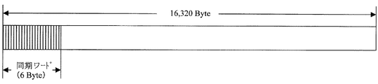
現在のOTN(Optical Transport Network)に適用されているフレーム構成の例を図1に示す。図1において、1フレームは16,320バイトからなっており、そのうち、同期ワードは先頭の6バイトが割り振られている。 FIG. 1 shows an example of a frame configuration applied to the current OTN (Optical Transport Network). In FIG. 1, one frame is composed of 16,320 bytes, of which the first 6 bytes are allocated as the synchronization word.
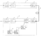
このようなフレーム構成に対して、従来の光送受信システムの構成を図2に示す。図2において、70は光送信装置、71はフレーム生成回路、72はFECエンコーダ、75は電気光変換回路、40は光ファイバ伝送路、80は光受信装置、85は光電気変換回路、82はFECデコーダ、81はフレーム終端回路、91は同期ワード検出回路、92はフレーム同期検出回路、93はフレーム同期はずれ検出回路、95は受信器フレーム同期表示回路である。 FIG. 2 shows the configuration of a conventional optical transmission / reception system for such a frame configuration. In FIG. 2, 70 is an optical transmission device, 71 is a frame generation circuit, 72 is an FEC encoder, 75 is an electro-optical conversion circuit, 40 is an optical fiber transmission line, 80 is an optical reception device, 85 is an optical / electrical conversion circuit, and 82 is The FEC decoder, 81 is a frame termination circuit, 91 is a synchronization word detection circuit, 92 is a frame synchronization detection circuit, 93 is a frame synchronization loss detection circuit, and 95 is a receiver frame synchronization display circuit.
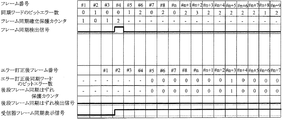
図2に示す光送受信システムの動作を表すタイムチャートを図3に示す。フレーム生成回路71で生成されたフレームを同期ワード検出回路91で同期ワードを検出する。図2において、フレーム同期検出回路92がフレーム番号#3、#4の同期ワードで連続してビットエラーのないことを検出すると、フレーム同期検出信号を出力する。受信器フレーム同期表示回路95はフレーム同期検出信号を検出すると、受信器フレーム同期表示信号をHighにする。これによって、光受信装置はフレーム同期を確立した状態となる。
FIG. 3 shows a time chart representing the operation of the optical transmission / reception system shown in FIG. A synchronization
光ファイバ伝送路のエラーレートが高くなると、OTNフレームの同期ワードにもエラーが含まれる確率が高くなる。フレーム同期はずれ検出回路93がフレーム番号#n+1から#n+7までの同期ワードで連続してビットエラーを検出すると、フレーム同期はずれ検出信号を出力する。受信器フレーム同期表示回路95は、フレーム同期はずれ検出信号を検出すると、受信器フレーム同期表示信号をLowにする。これによって、光受信装置はフレーム同期はずれ状態となる。
When the error rate of the optical fiber transmission line increases, the probability that an error is also included in the synchronization word of the OTN frame increases. When the frame synchronization
図2におけるFECデコーダ82がエラー訂正を行った結果、エラー訂正後のデータ信号に誤りが含まれないにも拘わらず、突然、受信器フレーム同期表示回路95が受信器フレーム同期表示信号をLowとするため、通信が遮断され、再度、上記のフレーム同期確立動作が完了するまでデータ信号が廃棄されることになる。光ファイバ伝送路のエラーレートが高い場合は、フレーム同期確立にも時間がかかるため、結局廃棄されるデータ信号が多くなり、通信回線のスループットが劣化するという課題が発生する。
As a result of the error correction by the
そこで、本願発明は、伝送路でビットエラーが生じても、フレーム同期はずれ状態に移行しにくいフレーム同期技術を提供することを目的とする。 In view of the above, an object of the present invention is to provide a frame synchronization technique that is unlikely to shift to an out of frame synchronization state even if a bit error occurs in a transmission line.
上記目的を達成するために、本願発明では、受信した光信号を電気信号に変換した後、電気信号のエラー訂正をし、フレーム同期が確立された後は、エラー訂正された電気信号の中から、許容値を超えたビットエラーを有する同期ワードの連続をカウントして規定数に達したときにフレーム同期はずれと判定する。 In order to achieve the above object, in the present invention, the received optical signal is converted into an electrical signal, then error correction of the electrical signal is performed, and after frame synchronization is established, the error-corrected electrical signal is selected. When the number of consecutive synchronization words having a bit error exceeding the allowable value is counted and reaches a specified number, it is determined that the frame synchronization is lost.
本願発明は、入力されるデータ信号に同期ワードを付加してフレーム付加電気信号を生成するフレーム生成回路と、前記フレーム生成回路からの前記フレーム付加電気信号にエラー訂正用の符号を付加してエラー訂正付加電気信号を生成するFEC(Forward Error Correction)エンコーダと、前記FECエンコーダからの前記エラー訂正付加電気信号を光信号に変換して送信する電気光変換回路と、を備える光送信装置及び前記電気光変換回路からの前記光信号を受信し、受信した光信号を光電気変換して前記エラー訂正付加電気信号を再生する光電気変換回路と、前記光電気変換回路からの前記エラー訂正付加電気信号から前記同期ワードを検出し、フレーム同期のとれたエラー訂正付加電気信号を出力する前段同期ワード検出回路と、前記前段同期ワード検出回路の検出する前記同期ワードのうちビットエラーのない同期ワードの連続をカウントして規定数に達したときにフレーム同期確立と判定し、フレーム同期検出信号を出力する前段フレーム同期検出回路と、前記前段同期ワード検出回路からの前記フレーム同期のとれたエラー訂正付加電気信号を前記同期ワードを含めてエラー訂正し、前記フレーム付加電気信号を再生するFECデコーダと、前記FECデコータからの前記フレーム付加電気信号に含まれる前記同期ワードのうち許容値を超えたビットエラーを有する同期ワードの連続をカウントして規定数に達したときにフレーム同期はずれと判定し、後段フレーム同期はずれ検出信号を出力する後段フレーム同期はずれ検出回路と、前記前段フレーム同期検出回路からの前記フレーム同期検出信号に基づいてフレーム同期確立状態とし、前記後段フレーム同期はずれ検出回路からの前記後段フレーム同期はずれ検出信号に基づいてフレーム同期はずれ状態とする受信器フレーム同期表示信号を出力する受信器フレーム同期表示出力回路と、前記FECデコーダからの前記フレーム付加電気信号から前記同期ワードを除去して前記データ信号を再生するフレーム終端回路と、を備える光受信装置を有する光送受信システムである。 The present invention includes a frame generation circuit that generates a frame-added electrical signal by adding a synchronization word to an input data signal, and an error correction code added to the frame-added electrical signal from the frame generation circuit. An optical transmission apparatus comprising: an FEC (Forward Error Correction) encoder that generates a correction-added electric signal; and an electric-optical conversion circuit that converts the error-correction-added electric signal from the FEC encoder into an optical signal and transmits the optical signal. A photoelectric conversion circuit that receives the optical signal from the optical conversion circuit, photoelectrically converts the received optical signal to reproduce the error correction additional electric signal, and the error correction additional electric signal from the photoelectric conversion circuit; Before detecting the synchronization word and outputting an error-correction-added electrical signal with frame synchronization A synchronization word detection circuit, and a synchronization signal detected by the preceding synchronization word detection circuit is counted when a synchronization word having no bit error is counted and reaches a specified number, and frame synchronization is established; And a FEC decoder for correcting the frame-synchronized error-corrected additional electric signal including the synchronous word and reproducing the frame-added electric signal from the previous-stage synchronous word detecting circuit. When the number of consecutive synchronization words having a bit error exceeding an allowable value among the synchronization words included in the frame-added electrical signal from the FEC decoder reaches a specified number, it is determined that the frame synchronization is lost. A post-stage frame sync loss detection circuit for outputting a post-frame sync error detection signal; Receiver frame synchronization that establishes frame synchronization based on the frame synchronization detection signal from the stage frame synchronization detection circuit, and sets frame synchronization out of synchronization based on the subsequent frame synchronization detection signal from the subsequent frame synchronization detection circuit A receiver frame synchronization display output circuit that outputs a display signal; and a frame termination circuit that removes the synchronization word from the frame-added electrical signal from the FEC decoder and reproduces the data signal. This is an optical transmission / reception system.
本願発明は、入力されるデータ信号に同期ワードを付加してフレーム付加電気信号を生成するフレーム生成手順と、前記フレーム生成手順の後、前記フレーム付加電気信号にエラー訂正用の符号を付加してエラー訂正付加電気信号を生成するFEC(Forward Error Correction)エンコード手順と、前記FECエンコーダ手順の後、前記エラー訂正付加電気信号を光信号に変換して送信する電気光変換手順と、前記電気光変換手順の後、前記光信号を受信し、受信した光信号を光電気変換して前記エラー訂正付加電気信号を再生する光電気変換手順と、前記光電気変換手順の後、前記エラー訂正付加電気信号から前記同期ワードを検出し、フレーム同期のとれたエラー訂正付加電気信号を出力する前段同期ワード検出手順と、前記前段同期ワード検出手順の後、前記前段同期ワード検出手順で検出する前記同期ワードのうちビットエラーのない同期ワードの連続をカウントして規定数に達したときにフレーム同期確立と判定し、フレーム同期検出信号を出力する前段フレーム同期検出手順と、前記前段フレーム同期検出手順の後、前記フレーム同期のとれたエラー訂正付加電気信号を前記同期ワードを含めてエラー訂正し、前記フレーム付加電気信号を再生するFECデコード手順と、前記FECデコード手順の後、前記フレーム付加電気信号に含まれる前記同期ワードのうち許容値を超えたビットエラーを有する同期ワードの連続をカウントして規定数に達したときにフレーム同期はずれと判定し、後段フレーム同期はずれ検出信号を出力する後段フレーム同期はずれ検出手順と、前記後段フレーム同期はずれ検出手順での前記後段フレーム同期はずれ検出信号に基づいてフレーム同期はずれ状態とする受信器フレーム同期表示信号を出力する受信器フレーム同期表示出力手順と、を備える光送受信手順である。 The present invention includes a frame generation procedure for generating a frame-added electrical signal by adding a synchronization word to an input data signal, and adding an error correction code to the frame-added electrical signal after the frame generation procedure. FEC (Forward Error Correction) encoding procedure for generating an error-correction-added electrical signal, an electro-optic conversion procedure for converting the error-correction-added electrical signal into an optical signal after the FEC encoder procedure, and the electro-optic conversion After the procedure, the optical signal is received, the received optical signal is photoelectrically converted to reproduce the error correction additional electrical signal, and after the photoelectric conversion procedure, the error correction additional electrical signal Detecting the sync word from the frame and outputting an error correction additional electrical signal with frame synchronization After the procedure and the preceding synchronization word detection procedure, it is determined that frame synchronization is established when the number of synchronization words having no bit error among the synchronization words detected by the preceding synchronization word detection procedure is counted and a prescribed number is reached. After the preceding frame synchronization detection procedure for outputting a frame synchronization detection signal, and after the preceding frame synchronization detection procedure, the frame-synchronized error correction additional electrical signal is error-corrected including the synchronization word, and the frame addition is performed. After the FEC decoding procedure for reproducing the electrical signal, and after the FEC decoding procedure, the synchronization word having a bit error exceeding an allowable value among the synchronization words included in the frame-added electrical signal is counted to a prescribed number. When it is reached, it is determined that the frame synchronization has been lost, and the latter frame that outputs the second frame synchronization detection signal is detected. Out of synchronization detection procedure, and Receiver frame synchronization display output procedure for outputting a receiver frame synchronization display signal to be out of frame synchronization based on the latter frame synchronization loss detection signal in the latter frame synchronization loss detection procedure. It is an optical transmission / reception procedure provided.
本願発明は、光信号を受信し、受信した光信号を光電気変換してエラー訂正付加電気信号を再生する光電気変換回路と、前記光電気変換回路からの前記エラー訂正付加電気信号から同期ワードを検出し、フレーム同期のとれたエラー訂正付加電気信号を出力する前段同期ワード検出回路と、前記前段同期ワード検出回路の検出する前記同期ワードのうちビットエラーのない同期ワードの連続をカウントして規定数に達したときにフレーム同期確立と判定し、フレーム同期検出信号を出力する前段フレーム同期検出回路と、前記前段同期ワード検出回路からの前記フレーム同期のとれたエラー訂正付加電気信号を前記同期ワードを含めてエラー訂正し、フレーム付加電気信号を再生するFECデコーダと、前記FECデコータからの前記フレーム付加電気信号に含まれる前記同期ワードのうち許容値を超えたビットエラーを有する同期ワードの連続をカウントして規定数に達したときにフレーム同期はずれと判定し、後段フレーム同期はずれ検出信号を出力する後段フレーム同期はずれ検出回路と、前記前段フレーム同期検出回路からの前記フレーム同期検出信号に基づいてフレーム同期確立状態とし、前記後段フレーム同期はずれ検出回路からの前記後段フレーム同期はずれ検出信号に基づいてフレーム同期はずれ状態とする受信器フレーム同期表示信号を出力する受信器フレーム同期表示出力回路と、前記FECデコーダからの前記フレーム付加電気信号から前記同期ワードを除去して前記データ信号を再生するフレーム終端回路と、を備える光受信装置である。 The invention of the present application includes a photoelectric conversion circuit that receives an optical signal, photoelectrically converts the received optical signal to reproduce an error correction additional electrical signal, and a synchronization word from the error correction additional electrical signal from the photoelectric conversion circuit. And detecting a synchronization signal having no bit error among the synchronization words detected by the preceding synchronization word detection circuit, and outputting an error correction additional electrical signal with frame synchronization. It determines that frame synchronization has been established when the specified number is reached, and outputs a frame synchronization detection signal, a previous frame synchronization detection circuit, and the frame-synchronized error correction additional electrical signal from the previous synchronization word detection circuit. An FEC decoder that corrects an error including a word and reproduces a frame-added electric signal, and the frame from the FEC decoder. Out of the synchronization words included in the additional electrical signal, the number of consecutive synchronization words with bit errors exceeding the allowable value is counted, and when the specified number is reached, it is determined that frame synchronization is lost, and the subsequent frame synchronization is output as a detection error signal. A frame synchronization establishment state based on the subsequent frame synchronization detection circuit and the frame synchronization detection signal from the preceding frame synchronization detection circuit, and based on the subsequent frame synchronization detection signal from the subsequent frame synchronization detection circuit. A receiver frame synchronization display output circuit for outputting a receiver frame synchronization display signal in an out-of-frame state, and a frame termination for reproducing the data signal by removing the synchronization word from the frame-added electrical signal from the FEC decoder And a circuit.
本願発明は、光信号を受信し、受信した光信号を光電気変換して前記エラー訂正付加電気信号を再生する光電気変換手順と、前記光電気変換手順の後、前記エラー訂正付加電気信号から前記同期ワードを検出し、フレーム同期のとれたエラー訂正付加電気信号を出力する前段同期ワード検出手順と、前記前段同期ワード検出手順の後、前記前段同期ワード検出手順で検出する前記同期ワードのうちビットエラーのない同期ワードの連続をカウントして規定数に達したときにフレーム同期確立と判定し、フレーム同期検出信号を出力する前段フレーム同期検出手順と、前記前段フレーム同期検出手順の後、前記フレーム同期のとれたエラー訂正付加電気信号を前記同期ワードを含めてエラー訂正し、前記フレーム付加電気信号を再生するFECデコード手順と、前記FECデコード手順の後、前記フレーム付加電気信号に含まれる前記同期ワードのうち許容値を超えたビットエラーを有する同期ワードの連続をカウントして規定数に達したときにフレーム同期はずれと判定し、後段フレーム同期はずれ検出信号を出力する後段フレーム同期はずれ検出手順と、前記後段フレーム同期はずれ検出手順での前記後段フレーム同期はずれ検出信号に基づいてフレーム同期はずれ状態とする受信器フレーム同期表示信号を出力する受信器フレーム同期表示出力手順と、を備える光受信手順である。 The present invention relates to a photoelectric conversion procedure for receiving an optical signal, photoelectrically converting the received optical signal to reproduce the error correction additional electrical signal, and after the photoelectric conversion procedure, from the error correction additional electrical signal. Of the synchronization word detected by the preceding synchronization word detection procedure after the preceding synchronization word detection procedure after detecting the synchronization word and outputting the frame-synchronized error correction additional electrical signal It is determined that frame synchronization is established when a predetermined number of synchronization word counts without bit errors are reached and a frame synchronization detection signal is output, and after the preceding frame synchronization detection procedure, the frame synchronization detection signal is output. FEC which corrects an error including an error correction additional electric signal including frame synchronization and reproduces the frame additional electric signal. After the code procedure and the FEC decoding procedure, frame synchronization is performed when the number of consecutive synchronization words having a bit error exceeding an allowable value among the synchronization words included in the frame-added electrical signal reaches a specified number A receiver frame that is determined to be out of sync and outputs a post-synchronization loss detection signal to a post-frame sync loss detection procedure, and a receiver frame that is out of frame synchronization based on the post-frame sync loss detection signal in the post-frame sync loss detection procedure A receiver frame synchronization display output procedure for outputting a synchronization display signal.
本願発明は、光信号を受信し、受信した光信号を光電気変換して前記エラー訂正付加電気信号を再生する光電気変換ステップと、前記光電気変換ステップの後、前記エラー訂正付加電気信号から前記同期ワードを検出し、フレーム同期のとれたエラー訂正付加電気信号を出力する前段同期ワード検出ステップと、前記前段同期ワード検出ステップの後、前記前段同期ワード検出ステップで検出する前記同期ワードのうちビットエラーのない同期ワードの連続をカウントして規定数に達したときにフレーム同期確立と判定し、フレーム同期検出信号を出力する前段フレーム同期検出ステップと、前記前段フレーム同期検出ステップの後、前記フレーム同期のとれたエラー訂正付加電気信号を前記同期ワードを含めてエラー訂正し、前記フレーム付加電気信号を再生するFECデコードステップと、前記FECデコードステップの後、前記フレーム付加電気信号に含まれる前記同期ワードのうち許容値を超えたビットエラーを有する同期ワードの連続をカウントして規定数に達したときにフレーム同期はずれと判定し、後段フレーム同期はずれ検出信号を出力する後段フレーム同期はずれ検出ステップと、前記後段フレーム同期はずれ検出ステップでの前記後段フレーム同期はずれ検出信号に基づいてフレーム同期はずれ状態とする受信器フレーム同期表示信号を出力する受信器フレーム同期表示出力ステップと、を備える受信ステップ、をコンピュータに実行させるための光受信プログラムである。 The invention of the present application receives an optical signal, photoelectrically converts the received optical signal to reproduce the error correction additional electrical signal, and after the photoelectric conversion step, from the error correction additional electrical signal Of the synchronization word detected in the preceding synchronization word detection step after the preceding synchronization word detection step, after detecting the synchronization word and outputting the frame-synchronized error correction additional electrical signal It is determined that frame synchronization is established when a predetermined number of synchronization words having no bit error are counted and reaches a specified number, and after the preceding frame synchronization detection step, outputting a frame synchronization detection signal, Error correction including an error correction additional electric signal with frame synchronization including the synchronization word, and the frame An FEC decoding step for reproducing the applied electric signal; and after the FEC decoding step, a prescribed number is obtained by counting consecutive synchronization words having a bit error exceeding an allowable value among the synchronization words included in the frame-added electric signal. Is determined to be out of frame synchronization, and a subsequent frame synchronization error detection step for outputting a subsequent frame synchronization error detection signal, and the subsequent frame synchronization error detection step in the subsequent frame synchronization error detection step, is performed based on the error detection signal. An optical reception program for causing a computer to execute a reception step comprising: a receiver frame synchronization display output step for outputting a receiver frame synchronization display signal to be in a disconnected state.
本願発明によれば、伝送路でビットエラーが生じても、フレーム同期はずれ状態に移行しにくいフレーム同期技術を提供することができる。 According to the present invention, it is possible to provide a frame synchronization technique in which even if a bit error occurs in a transmission path, it is difficult to shift to a frame synchronization out of state.
添付の図面を参照して本発明の実施形態を説明する。以下に説明する実施形態は本発明の実施例であり、本発明は、以下の実施形態に制限されるものではない。なお、本明細書及び図面において符号が同じ構成要素は、相互に同一のものを示すものとする。 Embodiments of the present invention will be described with reference to the accompanying drawings. The embodiments described below are examples of the present invention, and the present invention is not limited to the following embodiments. In the present specification and drawings, the same reference numerals denote the same components.
(実施形態1)
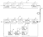
本実施形態の光送受信システムの構成例を図4に示す。図4において、光送受信システムは、光送信装置10及び光受信装置20を有し、両者は光ファイバ伝送路40で接続されている。光ファイバ伝送路40の途中には光中継器等が接続されていてもよい。
(Embodiment 1)
A configuration example of the optical transmission / reception system of this embodiment is shown in FIG. In FIG. 4, the optical transmission / reception system includes an
光送信装置10は、入力されるデータ信号に同期ワードを付加してフレーム付加電気信号を生成するフレーム生成回路11と、フレーム生成回路11からのフレーム付加電気信号にエラー訂正用の符号を付加してエラー訂正付加電気信号を生成するFEC(Forward Error Correction)エンコーダ12と、FECエンコーダ12からのエラー訂正付加電気信号を光信号に変換して送信する電気光変換回路15と、を備える。
The
光受信装置20は、電気光変換回路15からの光信号を受信し、受信した光信号を光電気変換してエラー訂正付加電気信号を再生する光電気変換回路25と、光電気変換回路25からのエラー訂正付加電気信号から同期ワードを検出し、フレーム同期のとれたエラー訂正付加電気信号を出力する前段同期ワード検出回路31と、前段同期ワード検出回路31の検出する同期ワードのうちビットエラーのない同期ワードの連続をカウントして規定数に達したときにフレーム同期確立と判定し、フレーム同期検出信号を出力する前段フレーム同期検出回路32と、前段同期ワード検出回路31からのフレーム同期のとれたエラー訂正付加電気信号を、同期ワードを含めてエラー訂正し、フレーム付加電気信号を再生するFECデコーダ22と、FECデコータ22からのフレーム付加電気信号に含まれる同期ワードのうち許容値を超えたビットエラーを有する同期ワードの連続をカウントして規定数に達したときにフレーム同期はずれと判定し、後段フレーム同期はずれ検出信号を出力する後段フレーム同期はずれ検出回路34と、前段フレーム同期検出回路32からのフレーム同期検出信号に基づいてフレーム同期確立状態とし、後段フレーム同期はずれ検出回路34からの後段フレーム同期はずれ検出信号に基づいてフレーム同期はずれ状態とする受信器フレーム同期表示信号を出力する受信器フレーム同期表示出力回路35と、FECデコーダ22からのフレーム付加電気信号から同期ワードを除去してデータ信号を再生するフレーム終端回路21と、を備える。
The
光受信装置20では、光電気変換回路25は受信した光信号を光電気変換してエラー訂正付加電気信号を再生する。前段同期ワード検出回路31は、光電気変換回路25からのエラー訂正付加電気信号から同期ワードを検出する。例えば、図1に示すようなONTフレーム構成であれば、フレームの先頭にある6バイトからなる同期ワードを検出する。同期ワードを検出すると、フレーム同期のとれたエラー訂正付加電気信号を出力する。前段フレーム同期検出回路32は、前段同期ワード検出回路31の検出する同期ワードのうちビットエラーのない同期ワードの連続を同期保護カウンタ(不図示)でカウントする。同期ワードの連続数が規定数に達したときにフレーム同期確立と判定し、フレーム同期検出信号を出力する。ビットエラーのない同期ワードの連続数の規定数をフレーム同期検出保護段数という。受信器フレーム同期表示出力回路35は、前段フレーム同期検出回路32からのフレーム同期検出信号に基づいてフレーム同期確立状態とする受信器フレーム同期表示信号を出力する。受信器フレーム同期表示出力回路35が、フレーム同期確立状態とする受信器フレーム同期表示信号を出力してから、前段同期ワード検出回路31は、フレーム同期のとれたエラー訂正付加電気信号を出力したり、フレーム終端回路21は、データ信号を出力したりしてもよい。
In the
FECデコーダ22は、前段同期ワード検出回路31からのフレーム同期のとれたエラー訂正付加電気信号を、同期ワードを含めてエラー訂正し、フレーム付加電気信号を再生する。フレーム付加電気信号はエラー訂正されているため、ビットエラーが少なくなっている。後段フレーム同期はずれ検出回路34は、FECデコータ22からのフレーム付加電気信号に含まれる同期ワードのうち許容値を超えたビットエラーを有する同期ワードの連続をカウントする。後段フレーム同期はずれ検出回路34は、ビットエラーを有する同期ワードの連続を後段同期はずれ保護カウンタ(不図示)でカウントする。後段フレーム同期はずれ検出回路34は、すでに同期ワードの位置が分かっているため、分かった位置のワードを予め決めておいた同期ワードと比較してもよい。ビットエラーを有する同期ワードの連続数が規定数に達したときにフレーム同期はずれと判定し、後段フレーム同期はずれ検出信号を出力する。同期ワードに含まれるビットエラーの許容限界を同期ワードビットエラー許容数という。同期ワードビットエラー許容数=1のときは、1ビットのエラーでもカウントを開始することを意味する。ビットエラーを有する同期ワードの連続数の規定数をフレーム同期はずれ検出保護段数という。受信器フレーム同期表示出力回路35は、後段フレーム同期はずれ検出回路34からの後段フレーム同期はずれ検出信号に基づいてフレーム同期はずれ状態とする受信器フレーム同期表示信号を出力する。
The
受信器フレーム同期表示出力回路35がフレーム同期はずれ状態とする受信器フレーム同期表示信号を出力すると、フレーム終端回路21は、データ信号の出力を中止したり、前段同期ワード検出回路31は、フレーム同期のとれたエラー訂正付加電気信号の出力を中止したり、前段同期ワード検出回路31は、同期ワードの探索を開始したりする。
When the receiver frame synchronization
本実施形態の後段フレーム同期はずれ検出回路34は、FECエンコーダ22の出力するエラー訂正のされたフレーム付加電気信号からビットエラーを有する同期ワードを検出するため、フレーム同期はずれとなる確率が少ない。そのため、不用意に後段フレーム同期はずれ検出信号を出力することはない。その結果、フレーム終端回路21が、データ信号の出力を中止したり、前段同期ワード検出回路31が、フレーム同期のとれたエラー訂正付加電気信号の出力を中止したり、前段同期ワード検出回路31が、同期ワードの探索を開始したりすることが少なくなる。つまり、フレーム同期はずれ状態に移行しにくい。
The
図4における光電気変換回路25の例として、図18にディジタルコヒレント光受信回路の例を示す。電気光変換回路15からの光信号がディジタルコヒレント光信号の場合の例である。ディジタルコヒレント光受信回路500は、光を直交する偏波光に分離する偏波ビームスプリッタ511、512、光を合成してI成分及びQ成分に分離する光ハイブリッド回路521、522、光信号を電気信号に変換するO/E変換部531、532、アナログ信号をディジタル信号に変換するA/D変換部541、542、ディジタル処理をして元のディジタル信号を再生するディジタル信号処理部550、入力する光信号と同じ又は同等の発振周波数で発振する局部発振光源560を備える。
As an example of the
光信号が偏波ビームスプリッタ511に入力されると、偏波ビームスプリッタ511でX方向とY方向の偏波光に分離される。局部発振光源560からの光信号が偏波ビームスプリッタ512に入力されると、偏波ビームスプリッタ512でX方向とY方向の偏波光に分離される。それぞれ同方向の偏波光は光ハイブリッド回路521、522で合成されて、I成分とQ成分に分離される。分離された光はO/E変換部531、532でそれぞれ電気信号に変換される。電気信号に変換された後、A/D変換部541、542でそれぞれI成分電気信号及びQ成分電気信号として出力される。ディジタル信号処理部550では、これらのI成分電気信号及びQ成分電気信号をディジタル信号処理して、元の信号を再生する。
When an optical signal is input to the
ここで説明したディジタルコヒレント光受信回路500は、以後の実施形態の光電気変換回路に適用することができる。
The digital coherent
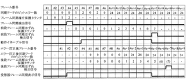
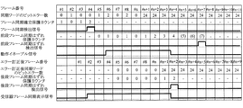
図4に示す光受信装置の動作を表すタイムチャートの例を図5に示す。図5において、フレーム同期検出保護段数=2、同期ワードビットエラー許容数=1、フレーム同期はずれ検出保護段数=7の例である。これらの数値は1例であって、これらの数値に限定されるものではない。#3、#4と2回続けて同期ワードにビットエラーが生じなかったため(同期確立保護カウンタ=2)となるため、前段フレーム同期検出回路32は、フレーム同期検出信号を出力する。これに伴い、受信器フレーム同期表示出力回路35は、受信器フレーム同期表示信号をフレーム同期確立状態であるHigh状態とする。
FIG. 5 shows an example of a time chart showing the operation of the optical receiver shown in FIG. FIG. 5 shows an example in which the frame synchronization detection protection stage number = 2, the synchronization word bit error allowable number = 1, and the frame synchronization loss detection protection stage number = 7. These numerical values are examples, and are not limited to these numerical values. Since no bit error has occurred in the synchronization word twice in # 3 and # 4 (synchronization establishment protection counter = 2), the preceding frame
エラー訂正後の同期ワードに含まれるビットエラーが少ないため、後段同期はずれ保護カウンタの値はほとんどが“0”である。そのため、連続してビットエラーを有する同期ワードが検出されることがないため、後段フレーム同期はずれ検出信号が出力されることはない。その結果、受信器フレーム同期表示信号は、フレーム同期確立状態であるHigh状態が維持される。 Since there are few bit errors included in the synchronization word after error correction, the value of the post-synchronization protection counter is almost “0”. For this reason, since a synchronization word having a bit error is not detected continuously, the subsequent frame synchronization loss detection signal is not output. As a result, the receiver frame synchronization display signal is maintained in the high state, which is the frame synchronization establishment state.
(実施形態2)
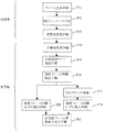
本実施形態の光送受信手順の例を図6に示す。図6において、光送受信方法は、入力されるデータ信号に同期ワードを付加してフレーム付加電気信号を生成するフレーム生成手順P11と、フレーム生成手順P11の後、フレーム付加電気信号にエラー訂正用の符号を付加してエラー訂正付加電気信号を生成するFEC(Forward Error Correction)エンコード手順P12と、FECエンコーダ手順P12の後、エラー訂正付加電気信号を光信号に変換して送信する電気光変換手順P13と、電気光変換手順P13の後、光信号を受信し、受信した光信号を光電気変換して前記エラー訂正付加電気信号を再生する光電気変換手順P14と、光電気変換手順P14の後、エラー訂正付加電気信号から同期ワードを検出し、フレーム同期のとれたエラー訂正付加電気信号を出力する前段同期ワード検出手順P15と、前段同期ワード検出手順P15の後、前段同期ワード検出手順P15で検出する同期ワードのうちビットエラーのない同期ワードの連続をカウントして規定数に達したときにフレーム同期確立と判定し、フレーム同期検出信号を出力する前段フレーム同期検出手順P16と、前段フレーム同期検出手順P16の後、フレーム同期のとれたエラー訂正付加電気信号を同期ワードを含めてエラー訂正し、フレーム付加電気信号を再生するFECデコード手順P17と、FECデコード手順P17の後、フレーム付加電気信号に含まれる同期ワードのうち許容値を超えたビットエラーを有する同期ワードの連続をカウントして規定数に達したときにフレーム同期はずれと判定し、後段フレーム同期はずれ検出信号を出力する後段フレーム同期はずれ検出手順P18と、後段フレーム同期はずれ検出手順P18での後段フレーム同期はずれ検出信号に基づいてフレーム同期はずれ状態とする受信器フレーム同期表示信号を出力する受信器フレーム同期表示出力手順P19と、を備える。
(Embodiment 2)
An example of the optical transmission / reception procedure of this embodiment is shown in FIG. In FIG. 6, the optical transmission / reception method includes a frame generation procedure P11 for adding a synchronization word to an input data signal to generate a frame-added electrical signal, and a frame-added electrical signal for error correction after the frame generation procedure P11. An FEC (Forward Error Correction) encoding procedure P12 that adds a code to generate an error-correction-added electrical signal, and an electro-optical conversion procedure P13 that converts the error-correction-added electrical signal into an optical signal and transmits it after the FEC encoder procedure P12. And after the electro-optic conversion procedure P13, after receiving the optical signal, opto-electrically convert the received optical signal to regenerate the error correction added electrical signal, after the opto-electric conversion procedure P14, The error correction additional electrical signal is detected from the error correction additional electrical signal, and the frame is synchronized with the error correction additional electrical signal. After the preceding synchronization word detection procedure P15 and the preceding synchronization word detection procedure P15, the number of synchronization words having no bit error among the synchronization words detected by the preceding synchronization word detection procedure P15 is counted to reach the specified number. Sometimes it is determined that frame synchronization has been established, and after the previous frame synchronization detection procedure P16 for outputting the frame synchronization detection signal, and after the previous frame synchronization detection procedure P16, an error correction additional electric signal including the synchronization word is included in the error. FEC decoding procedure P17 for correcting and reproducing the frame-added electrical signal, and after the FEC decoding procedure P17, the synchronization word having a bit error exceeding the allowable value among the synchronization words included in the frame-added electrical signal is counted. When the specified number is reached, it is determined that the frame synchronization is lost, and the subsequent frame synchronization should be A post-synchronization detection procedure P18 for outputting a detection signal, and a receiver for outputting a frame synchronization display signal based on the post-synchronization detection signal P2 in the post-synchronization detection procedure P18. Frame synchronization display output procedure P19.
本実施形態の後段フレーム同期はずれ検出手順P18では、FECエンコード手順P17でのエラー訂正のされたフレーム付加電気信号からビットエラーを有する同期ワードを検出するため、同期ワード中に含まれるビットエラーが少ない。そのため、不用意に後段フレーム同期はずれ検出信号が出力されることはない。その結果、データ信号の出力を中止したり、フレーム同期のとれたエラー訂正付加電気信号の出力を中止したり、同期ワードの探索を開始したりすることが少なくなる。つまり、フレーム同期はずれ状態に移行しにくい。 In the latter-stage frame synchronization detection procedure P18 of the present embodiment, since a synchronization word having a bit error is detected from the frame-added electric signal that has been error-corrected in the FEC encoding procedure P17, the number of bit errors contained in the synchronization word is small. . Therefore, the subsequent frame synchronization loss detection signal is not inadvertently output. As a result, it is less likely that the output of the data signal is stopped, the output of the error-correction-added electric signal with frame synchronization is stopped, or the search for the synchronization word is started. In other words, it is difficult to shift to a frame out-of-sync state.
(実施形態3)
本実施形態の光送受信システムの構成例を図7に示す。実施形態1との差は、光送信装置10において、FECエンコーダ12と電気光変換回路15との間にスクランブラ13が配置され、光受信装置20において、前段同期ワード検出回路31とFECデコーダ22との間にデスクランブラ23が配置されていることである。
(Embodiment 3)
A configuration example of the optical transmission / reception system of this embodiment is shown in FIG. The difference from the first embodiment is that the
スクランブラ13は、FECエンコーダ12からのエラー訂正付加電気信号を擬似ランダム信号でスクランブルする。スクランブルによって、“0”や“1”の同符号連続を防止したり、“0”と“1”の出現確率を等しくすることができる。デスクランブラ23は、スクランブルされた信号を元に戻す。本実施形態の光送受信システムは、スクランブラ13やデスクランブラ23が配置されても、実施形態1と同様の効果を発揮することができる。
The
(実施形態4)
本実施形態の光送受信システムの構成例を図8に示す。実施形態1との差は、光受信装置20が、前段同期ワード検出回路31の検出する同期ワードのうち許容値を超えたビットエラーを有する同期ワードの連続をカウントして規定数に達したときにフレーム同期はずれと判定し、前段フレーム同期はずれ検出信号を出力する前段フレーム同期はずれ検出回路33をさらに備え、受信器フレーム同期表示出力回路35は、前段フレーム同期検出回路32からのフレーム同期検出信号に基づいてフレーム同期確立状態とし、前段フレーム同期はずれ検出回路33からの前段フレーム同期はずれ検出信号又は後段フレーム同期はずれ検出回路34からの後段フレーム同期はずれ検出信号に基づいてフレーム同期はずれ状態とする受信器フレーム同期表示信号を出力する点である。
(Embodiment 4)
FIG. 8 shows a configuration example of the optical transmission / reception system of this embodiment. The difference from the first embodiment is that when the
受信器フレーム同期表示出力回路35が、前段フレーム同期はずれ検出回路33からの前段フレーム同期はずれ検出信号又は後段フレーム同期はずれ検出回路34からの後段フレーム同期はずれ検出信号のいずれを選択するかは、図9に示すセレクタで実現することができる。前段フレーム同期検出回路32がフレーム同期確立と判定してからは、後段フレーム同期はずれ検出回路34からの後段フレーム同期はずれ検出信号に基づいてフレーム同期はずれ状態とする。この判定は、動作イネーブル信号となって現れる。セレクタは受信器フレーム同期表示出力回路35の内部回路であり、動作イネーブル信号は受信器フレーム同期表示出力回路35の内部状態を示す。
Whether the receiver frame synchronization
本実施形態の受信器フレーム同期表示出力回路35は、フレーム同期確立後は、後段フレーム同期はずれ検出回路34からの後段フレーム同期はずれ検出信号に基づいてフレーム同期はずれ状態とする。後段フレーム同期はずれ検出回路34は、FECエンコーダ22の出力するエラー訂正のされたフレーム付加電気信号からビットエラーを有する同期ワードを検出するため、フレーム同期はずれとなる確率が少ない。そのため、不用意に後段フレーム同期はずれ検出信号を出力することはない。その結果、フレーム終端回路21が、データ信号の出力を中止したり、前段同期ワード検出回路31が、フレーム同期のとれたエラー訂正付加電気信号の出力を中止したり、前段同期ワード検出回路31が、同期ワードの探索を開始したりすることが少なくなる。つまり、フレーム同期はずれ状態に移行しにくい。
After the frame synchronization is established, the receiver frame synchronization
図8に示す光受信装置の動作を表すタイムチャートの例を図11に示す。図11において、フレーム同期検出保護段数=2、同期ワードビットエラー許容数=1、前段フレーム同期はずれ検出保護段数=後段フレーム同期はずれ検出保護段数=7の例である。これらの数値は1例であって、これらの数値に限定されるものではない。#3、#4と2回続けて同期ワードにビットエラーが生じなかったため(同期確立保護カウンタ=2)となるため、前段フレーム同期検出回路32は、フレーム同期検出信号を出力する。これに伴い、受信器フレーム同期表示出力回路35は、受信器フレーム同期表示信号をフレーム同期確立状態であるHigh状態とする。
An example of a time chart representing the operation of the optical receiver shown in FIG. 8 is shown in FIG. In FIG. 11, the number of frame synchronization detection protection stages = 2, the allowable number of synchronization word bit errors = 1, the number of preceding frame synchronization loss detection protection stages = the number of subsequent frame synchronization error detection protection stages = 7. These numerical values are examples, and are not limited to these numerical values. Since no bit error has occurred in the synchronization word twice in # 3 and # 4 (synchronization establishment protection counter = 2), the preceding frame
図11に示す動作イネーブル信号は、FECデコーダ22や後段フレーム同期はずれ検出回路34の処理遅延を考慮して同期検出信号が出力されてから、2フレーム後にHigh状態とされている。動作イネーブル信号がHigh状態になってからは、後段フレーム同期はずれ検出信号が出力されるまで、受信器フレーム同期表示信号はフレーム同期確立状態であるHigh状態のままである。
The operation enable signal shown in FIG. 11 is set to the High state two frames after the synchronization detection signal is output in consideration of the processing delay of the
(実施形態5)
本実施形態の光送受信システムは、図8に示す光送受信システムと構成は同じである。光受信装置の動作を表すタイムチャートの例を図12に示す。図12において、受信器フレーム同期表示出力回路35は、受信器フレーム同期表示信号をフレーム同期確立状態であるHigh状態とするまでは、実施形態4と同様と動作する。但し、前段フレーム同期はずれ検出信号又は後段フレーム同期はずれ検出信号のいずれかが出力されると、受信器フレーム同期表示出力回路35は、動作イネーブル信号をHigh状態からLow状態とする。図9に示すセレクタは、動作イネーブル信号がHigh状態からLow状態になることに伴い、受信器フレーム同期表示信号を前段フレーム同期はずれ検出信号に基づいて決定することになる。他の方法を図10に示す。図10は論理和回路である。フレーム同期確立後は、前段フレーム同期はずれ検出信号又は後段フレーム同期はずれ検出信号のいずれかが出力されると、受信器フレーム同期表示信号をLow状態とする。あるいは、受信器フレーム同期表示出力回路35は、前段フレーム同期はずれ検出信号のみに基づいてフレーム同期はずれ状態とすることでもよい。
(Embodiment 5)
The optical transmission / reception system of the present embodiment has the same configuration as the optical transmission / reception system shown in FIG. An example of a time chart showing the operation of the optical receiver is shown in FIG. In FIG. 12, the receiver frame synchronization
例えば、真のフレーム同期はずれの場合、“1”と“0”の出現確率がそれぞれ0.5で、同期ワードが6バイトとすると、同期ワードのビットエラー数は24ビットとなる。この場合、前段フレーム同期はずれ検出回路33の方が後段フレーム同期はずれ検出回路34よりも早くフレーム同期はずれを検出することができる。早めにフレーム同期はずれを検出できれば、前段同期ワード検出回路31は早めに同期ワードの探索を開始することができる。
For example, when true frame synchronization is lost, if the occurrence probabilities of “1” and “0” are 0.5 and the synchronization word is 6 bytes, the number of bit errors in the synchronization word is 24 bits. In this case, the previous frame synchronization
但し、前段フレーム同期はずれ検出回路33のビットエラー数の許容値が、後段フレーム同期はずれ検出回路34のビットエラー数の許容値よりも大きいことが望ましい。例えば、フレーム同期検出保護段数=2、前段フレーム同期はずれ検出の際の同期ワードビットエラー許容数=5、後段フレーム同期はずれ検出の際の同期ワードビットエラー許容数=1、前段フレーム同期はずれ検出保護段数=後段フレーム同期はずれ検出保護段数=7とする。これらの数値は1例であって、これらの数値に限定されるものではない。このような設定とすれば、前段フレーム同期はずれ検出回路33の方が後段フレーム同期はずれ検出回路34よりも早くフレーム同期はずれを検出することができ、その一方で、前段フレーム同期はずれ検出回路33が、わずかなビットエラーでフレーム同期はずれと判定してしまう確率が減少する。
However, it is desirable that the allowable value of the number of bit errors of the preceding frame
(実施形態6)
本実施形態の光送受信システムでは、図8に示す光送受信システムと構成は同じである。光受信装置の動作を表すタイムチャートの例を図13に示す。図13において、受信器フレーム同期表示出力回路35は、受信器フレーム同期表示信号をフレーム同期確立状態であるHigh状態とするまでは、実施形態4と同様に動作する。但し、前段フレーム同期はずれ検出信号又は後段フレーム同期はずれ検出信号のいずれかが出力されると、受信器フレーム同期表示出力回路35は、動作イネーブル信号をHigh状態からLow状態とする。図9に示すセレクタは、動作イネーブル信号がHigh状態からLow状態になることに伴い、受信器フレーム同期表示信号を前段フレーム同期はずれ検出信号に基づいて決定することになる。他の方法を図10に示す。図10は論理和回路である。フレーム同期確立後は、前段フレーム同期はずれ検出信号又は後段フレーム同期はずれ検出信号のいずれかが出力されると、受信器フレーム同期表示信号をLow状態とする。あるいは、受信器フレーム同期表示出力回路35は、後段フレーム同期はずれ検出信号のみに基づいてフレーム同期はずれ状態とすることでもよい。
(Embodiment 6)
The optical transmission / reception system of the present embodiment has the same configuration as the optical transmission / reception system shown in FIG. An example of a time chart showing the operation of the optical receiving apparatus is shown in FIG. In FIG. 13, the receiver frame synchronization
例えば、真のフレーム同期はずれの場合、“1”と“0”の出現確率がそれぞれ0.5で、同期ワードが6バイトとすると、同期ワードのビットエラー数は24ビットとなる。 ここで、後段フレーム同期はずれ検出回路34のカウントする許容値を超えたビットエラーを有する同期ワードの連続する規定数が、前段フレーム同期はずれ検出回路33のカウントする許容値を超えたビットエラーを有する同期ワードの連続する規定数よりも小さく設定することが望ましい。例えば、フレーム同期検出保護段数=2、前段フレーム同期はずれ検出の際の同期ワードビットエラー許容数=1、後段フレーム同期はずれ検出の際の同期ワードビットエラー許容数=1、前段フレーム同期はずれ検出保護段数=7、後段フレーム同期はずれ検出保護段数=2とする。これらの数値は1例であって、これらの数値に限定されるものではない。
For example, when true frame synchronization is lost, if the occurrence probabilities of “1” and “0” are 0.5 and the synchronization word is 6 bytes, the number of bit errors in the synchronization word is 24 bits. Here, the continuous prescribed number of synchronization words having a bit error exceeding the allowable value counted by the subsequent frame synchronization
この場合、後段フレーム同期はずれ検出回路34の方が、前段フレーム同期はずれ検出回路33よりも早くフレーム同期はずれを検出することができる。早めにフレーム同期はずれを検出できれば、前段同期ワード検出回路31は早めに同期ワードの探索を開始することができる。その一方で、前段フレーム同期はずれ検出回路33が、わずかなビットエラーでフレーム同期はずれと判定してしまう確率が減少する。
In this case, the latter frame synchronization
(実施形態7)
本実施形態の光送受信手順の例を図14に示す。図14において、光送受信方法は、入力されるデータ信号に同期ワードを付加してフレーム付加電気信号を生成するフレーム生成手順P11と、フレーム生成手順P11の後、フレーム付加電気信号にエラー訂正用の符号を付加してエラー訂正付加電気信号を生成するFEC(Forward Error Correction)エンコード手順P12と、FECエンコーダ手順P12の後、エラー訂正付加電気信号を光信号に変換して送信する電気光変換手順P13と、電気光変換手順P13の後、光信号を受信し、受信した光信号を光電気変換して前記エラー訂正付加電気信号を再生する光電気変換手順P14と、光電気変換手順P14の後、エラー訂正付加電気信号から同期ワードを検出し、フレーム同期のとれたエラー訂正付加電気信号を出力する前段同期ワード検出手順P15と、前段同期ワード検出手順P15の後、前段同期ワード検出手順P15で検出する同期ワードのうちビットエラーのない同期ワードの連続をカウントして規定数に達したときにフレーム同期確立と判定し、フレーム同期検出信号を出力する前段フレーム同期検出手順P16と、前段フレーム同期検出手順P16の後、フレーム同期のとれたエラー訂正付加電気信号を同期ワードを含めてエラー訂正し、フレーム付加電気信号を再生するFECデコード手順P17と、FECデコード手順P17の後、フレーム付加電気信号に含まれる同期ワードのうち許容値を超えたビットエラーを有する同期ワードの連続をカウントして規定数に達したときにフレーム同期はずれと判定し、後段フレーム同期はずれ検出信号を出力する後段フレーム同期はずれ検出手順P18と、前段同期ワード検出手順P15の後、前段同期ワード検出手順P15で検出する同期ワードのうちビットエラーのない同期ワードの連続をカウントして規定数に達したときにフレーム同期確立と判定し、フレーム同期検出信号を出力する前段フレーム同期はずれ検出手順P20と、前段フレーム同期はずれ検出手順P20での前段フレーム同期はずれ検出信号又は後段フレーム同期はずれ検出手順P18での後段フレーム同期はずれ検出信号に基づいてフレーム同期はずれ状態とする受信器フレーム同期表示信号を出力する前記受信器フレーム同期表示出力手順P21と、を備える。
(Embodiment 7)
An example of an optical transmission / reception procedure of this embodiment is shown in FIG. In FIG. 14, the optical transmission / reception method includes a frame generation procedure P11 for adding a synchronization word to an input data signal to generate a frame additional electrical signal, and after the frame generation procedure P11, the frame additional electrical signal is used for error correction. An FEC (Forward Error Correction) encoding procedure P12 that adds a code to generate an error-correction-added electrical signal, and an electro-optical conversion procedure P13 that converts the error-correction-added electrical signal into an optical signal and transmits it after the FEC encoder procedure P12. And after the electro-optic conversion procedure P13, after receiving the optical signal, opto-electrically convert the received optical signal to regenerate the error correction added electrical signal, after the opto-electric conversion procedure P14, Error correction additional electricity is detected by detecting a synchronization word from the error correction additional electric signal and synchronizing the frame. After the preceding synchronization word detection procedure P15 for outputting a signal and the previous synchronization word detection procedure P15, the number of synchronization words having no bit error among the synchronization words detected by the preceding synchronization word detection procedure P15 is counted to reach the specified number. Frame synchronization detection procedure P16 for determining that frame synchronization has been established and outputting the frame synchronization detection signal, and after the previous frame synchronization detection procedure P16, the error-correction-added electric signal with frame synchronization is included including the synchronization word. FEC decoding procedure P17 for error correction and reproduction of frame-added electrical signal, and after FEC decoding procedure P17, counts of synchronization words having bit errors exceeding the allowable value among the synchronization words included in the frame-added electrical signal When the specified number is reached, it is determined that the frame synchronization has been lost. Subsequent frame synchronization loss detection procedure P18 for outputting a deviation detection signal, and pre-synchronization word detection procedure P15, followed by counting the synchronization words without bit errors among the synchronization words detected in the pre-synchronization word detection procedure P15. It is determined that frame synchronization has been established when the number reaches, and the previous frame synchronization loss detection procedure P20 for outputting a frame synchronization detection signal, and the previous frame synchronization error detection procedure or the subsequent frame synchronization error detection in the previous frame synchronization error detection procedure P20. A receiver frame synchronization display output procedure P21 for outputting a receiver frame synchronization display signal that makes the frame synchronization out of sync based on the subsequent frame synchronization detection signal in step P18.
本実施形態では、後段フレーム同期はずれ検出信号又は前段フレーム同期はずれ検出信号に基づいてフレーム同期はずれとするため、不用意に後段フレーム同期はずれ検出信号が出力されることはない。その結果、データ信号の出力を中止したり、フレーム同期のとれたエラー訂正付加電気信号の出力を中止したり、同期ワードの探索を開始したりすることが少なくなる。 In this embodiment, since the frame synchronization is shifted based on the subsequent frame synchronization detection signal or the previous frame synchronization detection signal, the subsequent frame synchronization detection signal is not inadvertently output. As a result, it is less likely that the output of the data signal is stopped, the output of the error-correction-added electric signal with frame synchronization is stopped, or the search for the synchronization word is started.
受信器フレーム同期表示出力手順P21では、前段フレーム同期はずれ検出信号又は後段フレーム同期はずれ検出信号のいずれかが出力されるとフレーム同期はずれ状態としてもよいし、後段フレーム同期はずれ検出信号のみに基づいてフレーム同期はずれ状態としてもよい。 In the receiver frame synchronization display output procedure P21, when either the previous frame synchronization loss detection signal or the subsequent frame synchronization loss detection signal is output, the frame synchronization may be shifted, or the subsequent frame synchronization is based only on the shift detection signal. The frame synchronization may be lost.
本実施形態の後段フレーム同期はずれ検出手順P18では、エラー訂正された後にフレーム同期はずれを検出すため、不用意に後段フレーム同期はずれ検出信号が出力されることはない。また、前段フレーム同期はずれ検出信号と後段フレーム同期はずれ検出信号のいずれかに基づいて、フレーム同期はずれとすると、早くフレーム同期はずれを検出することができる。早めにフレーム同期はずれを検出できれば、早めに同期ワードの探索を開始することができる。 In the latter-stage frame synchronization detection procedure P18 of this embodiment, since the frame synchronization error is detected after error correction, the subsequent-frame synchronization error detection signal is not inadvertently output. Further, if frame synchronization is lost based on either the preceding frame synchronization loss detection signal or the subsequent frame synchronization error detection signal, the frame synchronization error can be detected quickly. If the frame synchronization loss can be detected early, the search for the synchronization word can be started early.
前段フレーム同期はずれ検出手順P20でのビットエラー数の許容値が、後段フレーム同期はずれ検出手順P18でのビットエラー数の許容値よりも大きいことが望ましい。この場合、受信器フレーム同期表示出力手順P21では、前段フレーム同期はずれ検出信号又は後段フレーム同期はずれ検出信号のいずれかが出力されるとフレーム同期はずれ状態としてもよいし、前段フレーム同期はずれ検出信号のみに基づいてフレーム同期はずれ状態としてもよい。 It is desirable that the allowable value of the number of bit errors in the preceding frame synchronization loss detection procedure P20 is larger than the allowable value of the number of bit errors in the subsequent frame synchronization error detection procedure P18. In this case, in the receiver frame synchronization display output procedure P21, when either the preceding frame synchronization error detection signal or the subsequent frame synchronization error detection signal is output, the frame synchronization error may occur or only the preceding frame synchronization error signal is detected. The frame synchronization may be lost based on the above.
例えば、フレーム同期検出保護段数=2、前段フレーム同期はずれ検出の際の同期ワードビットエラー許容数=5、後段フレーム同期はずれ検出の際の同期ワードビットエラー許容数=1、前段フレーム同期はずれ検出保護段数=後段フレーム同期はずれ検出保護段数=7とする。これらの数値は1例であって、これらの数値に限定されるものではない。このような設定とすれば、前段フレーム同期はずれ検出手順P20の方が後段フレーム同期はずれ検出手順P18よりも早くフレーム同期はずれが検出されることができ、その一方で、前段フレーム同期はずれ検出手順P20では、わずかなビットエラーでフレーム同期はずれと判定してしまう確率が減少する。 For example, the number of frame synchronization detection protection stages = 2, the allowable number of synchronization word bit errors when detecting out-of-frame frame synchronization detection = 5, the allowable number of synchronization word bit errors when detecting out-of-frame frame synchronization detection = 1, and the detection of out-of-frame synchronization error detection The number of stages = the number of post-frame synchronization loss detection protection stages = 7. These numerical values are examples, and are not limited to these numerical values. With such a setting, it is possible to detect the frame synchronization loss earlier in the preceding frame synchronization detection procedure P20 than in the subsequent frame synchronization detection procedure P18, while on the other hand, the previous frame synchronization detection procedure P20. Then, the probability that it is determined that frame synchronization is lost due to a slight bit error is reduced.
後段フレーム同期はずれ検出手順P18でのカウントする許容値を超えたビットエラーを有する同期ワードの連続する規定数が、前段フレーム同期はずれ検出手順P20でのカウントする許容値を超えたビットエラーを有する同期ワードの連続する規定数よりも小さいことが望ましい。この場合、受信器フレーム同期表示出力手順P21では、前段フレーム同期はずれ検出信号又は後段フレーム同期はずれ検出信号のいずれかが出力されるとフレーム同期はずれ状態としてもよいし、後段フレーム同期はずれ検出信号のみに基づいてフレーム同期はずれ状態としてもよい。 Synchronization in which the prescribed number of consecutive synchronization words having a bit error exceeding the allowable value counted in the subsequent frame synchronization detection procedure P18 has a bit error exceeding the allowable value counted in the previous frame synchronization detection procedure P20 It is desirable that it be smaller than the prescribed number of consecutive words. In this case, in the receiver frame synchronization display output procedure P21, when either the preceding frame synchronization loss detection signal or the subsequent frame synchronization error detection signal is output, the frame synchronization may be lost, or only the subsequent frame synchronization error detection signal is output. The frame synchronization may be lost based on the above.
例えば、フレーム同期検出保護段数=2、前段フレーム同期はずれ検出の際の同期ワードビットエラー許容数=1、後段フレーム同期はずれ検出の際の同期ワードビットエラー許容数=1、前段フレーム同期はずれ検出保護段数=7、後段フレーム同期はずれ検出保護段数=2とする。これらの数値は1例であって、これらの数値に限定されるものではない。 For example, the number of frame synchronization detection protection stages = 2, the allowable number of synchronization word bit errors at the time of detection of out-of-frame frame synchronization detection = 1, the allowable number of synchronization word bit errors at the time of detection of out-of-frame frame synchronization outage = 1, It is assumed that the number of stages = 7 and the number of post-frame synchronization loss detection protection stages = 2. These numerical values are examples, and are not limited to these numerical values.
この場合、後段フレーム同期はずれ検出手順P18の方が前段フレーム同期はずれ検出手順P20よりも早くフレーム同期はずれが検出されることができる。早めにフレーム同期はずれを検出できれば、早めに同期ワードの探索を開始することができる。その一方で、前段フレーム同期はずれ検出手順P20で、わずかなビットエラーでフレーム同期はずれと判定してしまう確率が減少する。 In this case, the frame synchronization loss can be detected earlier in the subsequent frame synchronization detection procedure P18 than in the previous frame synchronization detection procedure P20. If the frame synchronization loss can be detected early, the search for the synchronization word can be started early. On the other hand, in the preceding frame loss detection procedure P20, the probability that frame synchronization is determined to be lost due to a slight bit error is reduced.
(実施形態8)
本実施形態の光送受信システムの構成例を図15に示す。実施形態4、5、6との差は、光送信装置10において、FECエンコーダ12と電気光変換回路15との間にスクランブラ13が配置され、光受信装置20において、前段同期ワード検出回路31とFECデコーダ22との間にデスクランブラ23が配置されていることである。
(Embodiment 8)
A configuration example of the optical transmission / reception system of this embodiment is shown in FIG. The difference from the fourth, fifth, and sixth embodiments is that the
スクランブラ13は、FECエンコーダ12からのエラー訂正付加電気信号を擬似ランダム信号でスクランブルする。スクランブルによって、“0”や“1”の同符号連続を防止したり、“0”と“1”の出現確率を等しくすることができる。デスクランブラ23は、スクランブルされた信号を元に戻す。スクランブラ13やデスクランブラ23が配置されても、実施形態4、5、6と同様の効果を発揮することができる。
The
(実施形態9)
本実施形態のコンピュータに実行させるための光受信プログラムの例を図16に示す。図16において、光信号を受信し、受信した光信号を光電気変換して前記エラー訂正付加電気信号を再生する光電気変換ステップS14と、光電気変換ステップS14の後、エラー訂正付加電気信号から同期ワードを検出し、フレーム同期のとれたエラー訂正付加電気信号を出力する前段同期ワード検出ステップS15と、前段同期ワード検出ステップS15の後、前段同期ワード検出ステップS15で検出する同期ワードのうちビットエラーのない同期ワードの連続をカウントして規定数に達したときにフレーム同期確立と判定し、フレーム同期検出信号を出力する前段フレーム同期検出ステップS16と、前段フレーム同期検出ステップS16の後、フレーム同期のとれたエラー訂正付加電気信号を同期ワードを含めてエラー訂正し、フレーム付加電気信号を再生するFECデコードステップS17と、FECデコードステップS17の後、フレーム付加電気信号に含まれる同期ワードのうち許容値を超えたビットエラーを有する同期ワードの連続をカウントして規定数に達したときにフレーム同期はずれと判定し、後段フレーム同期はずれ検出信号を出力する後段フレーム同期はずれ検出ステップS18と、後段フレーム同期はずれ検出ステップS18での後段フレーム同期はずれ検出信号に基づいてフレーム同期はずれ状態とする受信器フレーム同期表示信号を出力する受信器フレーム同期表示出力ステップS19と、を備える。
(Embodiment 9)
An example of an optical reception program to be executed by the computer of this embodiment is shown in FIG. In FIG. 16, an optical signal is received, photoelectric conversion is performed on the received optical signal to reproduce the error correction additional electric signal, and after the photoelectric conversion step S14, the error correction additional electric signal is used. A synchronization word is detected and a frame-synchronized error correction additional electrical signal is output. The synchronization signal detection step S15 and a synchronization word detected in the synchronization word detection step S15 after the synchronization word detection step S15 are detected. It is determined that frame synchronization is established when the number of consecutive synchronization words without error is reached and reaches a specified number, and a frame synchronization detection step S16 for outputting a frame synchronization detection signal, and a frame after the preceding frame synchronization detection step S16, Error-corrected additional electrical signals including synchronized words are error-corrected and synchronized. FEC decoding step S17 for reproducing the frame additional electric signal, and after the FEC decoding step S17, the continuation of the synchronizing word having the bit error exceeding the allowable value among the synchronizing words included in the frame additional electric signal is counted and specified. When the number reaches the number, the frame synchronization is determined to be out of synchronization, and a post-stage frame synchronization out-of-phase detection step S18 for outputting a post-stage frame out-of-phase detection signal and a post-stage frame out-of-sync detection step S18 And a receiver frame synchronization display output step S19 for outputting a receiver frame synchronization display signal to be out of synchronization.
本実施形態では、後段フレーム同期はずれ検出信号又は前段フレーム同期はずれ検出信号に基づいてフレーム同期はずれとするため、不用意に後段フレーム同期はずれ検出信号が出力されることはない。その結果、光受信装置が、データ信号の出力を中止したり、フレーム同期のとれたエラー訂正付加電気信号の出力を中止したり、同期ワードの探索を開始したりすることが少なくなる。つまり、フレーム同期はずれ状態に移行しにくい。 In this embodiment, since the frame synchronization is shifted based on the subsequent frame synchronization detection signal or the previous frame synchronization detection signal, the subsequent frame synchronization detection signal is not inadvertently output. As a result, the optical receiving apparatus is less likely to stop outputting the data signal, stop outputting the error-correction-added electrical signal that is in frame synchronization, or start searching for a synchronization word. In other words, it is difficult to shift to a frame out-of-sync state.
(実施形態10)
本実施形態のコンピュータに実行させるための光受信プログラムの例を図17に示す。図17において、光受信プログラムは、光信号を受信し、受信した光信号を光電気変換して前記エラー訂正付加電気信号を再生する光電気変換ステップS14と、光電気変換ステップS14の後、エラー訂正付加電気信号から同期ワードを検出し、フレーム同期のとれたエラー訂正付加電気信号を出力する前段同期ワード検出ステップS15と、前段同期ワード検出ステップS15の後、前段同期ワード検出ステップS15で検出する同期ワードのうちビットエラーのない同期ワードの連続をカウントして規定数に達したときにフレーム同期確立と判定し、フレーム同期検出信号を出力する前段フレーム同期検出ステップS16と、前段フレーム同期検出ステップS16の後、フレーム同期のとれたエラー訂正付加電気信号を同期ワードを含めてエラー訂正し、フレーム付加電気信号を再生するFECデコードステップS17と、FECデコードステップS17の後、フレーム付加電気信号に含まれる同期ワードのうち許容値を超えたビットエラーを有する同期ワードの連続をカウントして規定数に達したときにフレーム同期はずれと判定し、後段フレーム同期はずれ検出信号を出力する後段フレーム同期はずれ検出ステップS18と、前段同期ワード検出ステップS16の後、前段同期ワード検出ステップS15で検出する同期ワードのうちビットエラーのない同期ワードの連続をカウントして規定数に達したときにフレーム同期確立と判定し、フレーム同期検出信号を出力する前段フレーム同期検出ステップS20と、前段フレーム同期はずれ検出ステップS20での前段フレーム同期はずれ検出信号又は後段フレーム同期はずれ検出ステップS18での後段フレーム同期はずれ検出信号に基づいてフレーム同期はずれ状態とする受信器フレーム同期表示信号を出力する前記受信器フレーム同期表示出力ステップS21と、を備える。
(Embodiment 10)
An example of an optical reception program to be executed by the computer of this embodiment is shown in FIG. In FIG. 17, the optical reception program receives an optical signal, photoelectrically converts the received optical signal to reproduce the error-correcting additional electric signal, and after the photoelectric conversion step S14, an error is detected. A sync word is detected from the corrected additional electrical signal, and an error corrected additional electrical signal with frame synchronization is output. After the preceding sync word detecting step S15, and after the preceding sync word detecting step S15, it is detected at the preceding sync word detecting step S15. A preceding frame synchronization detection step S16 that determines that frame synchronization is established when a predetermined number of synchronization words without bit errors are counted and reaches a specified number, and outputs a frame synchronization detection signal, and a preceding frame synchronization detection step After S16, the frame-synchronized error correction additional electrical signal includes the synchronization word. FEC decoding step S17 for correcting the error and reproducing the frame-added electric signal, and after the FEC decoding step S17, the continuation of the sync word having a bit error exceeding the allowable value among the sync words included in the frame-added electric signal When the count reaches the specified number, it is determined that the frame synchronization is out of sync, and the post-stage frame out-of-sync detection step S18 for outputting the post-stage frame out-of-sync detection signal, the pre-stage sync word detection step S16, and the pre-stage sync word detection step S15. In the preceding frame synchronization detection step S20 for counting the number of consecutive synchronization words having no bit error among the synchronization words detected in step S1 and determining that the frame synchronization is established when the prescribed number is reached and outputting the frame synchronization detection signal, The pre-stage frame in the loss of synchronization detection step S20 The receiver frame synchronization display output step S21 for outputting a receiver frame synchronization display signal for setting the frame synchronization to be shifted based on the subsequent frame synchronization loss detection signal in the subsequent frame synchronization detection signal or the subsequent frame synchronization detection signal in the subsequent frame synchronization detection step S18; Is provided.
本実施形態では、後段フレーム同期はずれ検出信号又は前段フレーム同期はずれ検出信号に基づいてフレーム同期はずれとするため、不用意に後段フレーム同期はずれ検出信号が出力されることはない。その結果、光受信装置が、データ信号の出力を中止したり、フレーム同期のとれたエラー訂正付加電気信号の出力を中止したり、同期ワードの探索を開始したりすることが少なくなる。 In this embodiment, since the frame synchronization is shifted based on the subsequent frame synchronization detection signal or the previous frame synchronization detection signal, the subsequent frame synchronization detection signal is not inadvertently output. As a result, the optical receiving apparatus is less likely to stop outputting the data signal, stop outputting the error-correction-added electrical signal that is in frame synchronization, or start searching for a synchronization word.
受信器フレーム同期表示出力ステップS21では、前段フレーム同期はずれ検出信号又は後段フレーム同期はずれ検出信号のいずれかが出力されるとフレーム同期はずれ状態としてもよいし、後段フレーム同期はずれ検出信号のみに基づいてフレーム同期はずれ状態としてもよい。 In the receiver frame synchronization display output step S21, when either the preceding frame synchronization loss detection signal or the subsequent frame synchronization loss detection signal is output, the frame synchronization may be shifted, or the subsequent frame synchronization is based only on the shift detection signal. The frame synchronization may be lost.
本実施形態の後段フレーム同期はずれ検出ステップでは、エラー訂正された後にフレーム同期はずれを検出すため、不用意に後段フレーム同期はずれ検出信号が出力されることはない。また、前段フレーム同期はずれ検出信号と後段フレーム同期はずれ検出信号のいずれかに基づいて、フレーム同期はずれとすると、早くフレーム同期はずれを検出することができる。早めにフレーム同期はずれを検出できれば、早めに同期ワードの探索を開始することができる。 In the latter-stage frame synchronization detection step of this embodiment, since the frame-synchronization is detected after error correction, the subsequent-frame synchronization detection signal is not inadvertently output. Further, if frame synchronization is lost based on either the preceding frame synchronization loss detection signal or the subsequent frame synchronization error detection signal, the frame synchronization error can be detected quickly. If the frame synchronization loss can be detected early, the search for the synchronization word can be started early.
前段フレーム同期はずれ検出ステップS20でのビットエラー数の許容値が、後段フレーム同期はずれ検出ステップS18でのビットエラー数の許容値よりも大きいことが望ましい。この場合、受信器フレーム同期表示出力ステップS21では、前段フレーム同期はずれ検出信号又は後段フレーム同期はずれ検出信号のいずれかが入力されるとフレーム同期はずれ状態としてもよいし、前段フレーム同期はずれ検出信号のみに基づいてフレーム同期はずれ状態としてもよい。 It is desirable that the allowable value of the number of bit errors in the preceding frame synchronization detection step S20 is larger than the allowable value of the number of bit errors in the subsequent frame synchronization detection step S18. In this case, in the receiver frame synchronization display output step S21, when either the preceding frame synchronization error detection signal or the subsequent frame synchronization error detection signal is input, the frame synchronization may be lost, or the preceding frame synchronization error detection signal only. The frame synchronization may be lost based on the above.
例えば、フレーム同期検出保護段数=2、前段フレーム同期はずれ検出の際の同期ワードビットエラー許容数=5、後段フレーム同期はずれ検出の際の同期ワードビットエラー許容数=1、前段フレーム同期はずれ検出保護段数=後段フレーム同期はずれ検出保護段数=7とする。これらの数値は1例であって、これらの数値に限定されるものではない。このような設定とすれば、前段フレーム同期はずれ検出ステップS20の方が後段フレーム同期はずれ検出ステップS18よりも早くフレーム同期はずれが検出されることができ、その一方で、前段フレーム同期はずれ検出ステップS20では、わずかなビットエラーでフレーム同期はずれと判定してしまう確率が減少する。 For example, the number of frame synchronization detection protection stages = 2, the allowable number of synchronization word bit errors when detecting out-of-frame frame synchronization detection = 5, the allowable number of synchronization word bit errors when detecting out-of-frame frame synchronization detection = 1, and the detection of out-of-frame synchronization error detection The number of stages = the number of post-frame synchronization loss detection protection stages = 7. These numerical values are examples, and are not limited to these numerical values. With this setting, it is possible to detect a frame synchronization loss in the preceding frame synchronization detection step S20 earlier than the subsequent frame synchronization detection step S18, while the preceding frame synchronization detection step S20. Then, the probability that it is determined that frame synchronization is lost due to a slight bit error is reduced.
後段フレーム同期はずれ検出ステップS18でのカウントする許容値を超えたビットエラーを有する同期ワードの連続する規定数が、前段フレーム同期はずれ検出ステップS20でのカウントする許容値を超えたビットエラーを有する同期ワードの連続する規定数よりも小さいことが望ましい。この場合、受信器フレーム同期表示出力ステップS21では、前段フレーム同期はずれ検出信号又は後段フレーム同期はずれ検出信号のいずれかが出力されるとフレーム同期はずれ状態としてもよいし、後段フレーム同期はずれ検出信号のみに基づいてフレーム同期はずれ状態としてもよい。 Synchronization in which the prescribed number of consecutive synchronization words having a bit error exceeding the allowable value counted in the subsequent frame synchronization loss detection step S18 has a bit error exceeding the allowable value counted in the previous frame synchronization loss detection step S20. It is desirable that it be smaller than the prescribed number of consecutive words. In this case, in the receiver frame synchronization display output step S21, when either the preceding frame synchronization loss detection signal or the subsequent frame synchronization error detection signal is output, the frame synchronization may be lost, or only the subsequent frame synchronization error detection signal is output. The frame synchronization may be lost based on the above.
例えば、フレーム同期検出保護段数=2、前段フレーム同期はずれ検出の際の同期ワードビットエラー許容数=1、後段フレーム同期はずれ検出の際の同期ワードビットエラー許容数=1、前段フレーム同期はずれ検出保護段数=7、後段フレーム同期はずれ検出保護段数=2とする。これらの数値は1例であって、これらの数値に限定されるものではない。 For example, the number of frame synchronization detection protection stages = 2, the allowable number of synchronization word bit errors at the time of detection of out-of-frame frame synchronization detection = 1, the allowable number of synchronization word bit errors at the time of detection of out-of-frame frame synchronization outage = 1, It is assumed that the number of stages = 7 and the number of post-frame synchronization loss detection protection stages = 2. These numerical values are examples, and are not limited to these numerical values.
この場合、後段フレーム同期はずれ検出ステップS18の方が前段フレーム同期はずれ検出ステップS20よりも早くフレーム同期はずれが検出されることができる。早めにフレーム同期はずれを検出できれば、早めに同期ワードの探索を開始することができる。その一方で、前段フレーム同期はずれ検出ステップS20では、わずかなビットエラーでフレーム同期はずれと判定してしまう確率が減少する。 In this case, the frame synchronization loss can be detected earlier in the subsequent frame synchronization detection step S18 than in the previous frame synchronization detection step S20. If the frame synchronization loss can be detected early, the search for the synchronization word can be started early. On the other hand, in the preceding frame loss detection step S20, the probability that frame synchronization is determined to be lost due to a slight bit error is reduced.
(付記1)
入力されるデータ信号に同期ワードを付加してフレーム付加電気信号を生成するフレーム生成回路と、
前記フレーム生成回路からの前記フレーム付加電気信号にエラー訂正用の符号を付加してエラー訂正付加電気信号を生成するFEC(Forward Error Correction)エンコーダと、
前記FECエンコーダからの前記エラー訂正付加電気信号を光信号に変換して送信する電気光変換回路と、
を備える光送信装置及び
前記電気光変換回路からの前記光信号を受信し、受信した光信号を光電気変換して前記エラー訂正付加電気信号を再生する光電気変換回路と、
前記光電気変換回路からの前記エラー訂正付加電気信号から前記同期ワードを検出し、フレーム同期のとれたエラー訂正付加電気信号を出力する前段同期ワード検出回路と、
前記前段同期ワード検出回路の検出する前記同期ワードのうちビットエラーのない同期ワードの連続をカウントして規定数に達したときにフレーム同期確立と判定し、フレーム同期検出信号を出力する前段フレーム同期検出回路と、
前記前段同期ワード検出回路からの前記フレーム同期のとれたエラー訂正付加電気信号を前記同期ワードを含めてエラー訂正し、前記フレーム付加電気信号を再生するFECデコーダと、
前記FECデコータからの前記フレーム付加電気信号に含まれる前記同期ワードのうち許容値を超えたビットエラーを有する同期ワードの連続をカウントして規定数に達したときにフレーム同期はずれと判定し、後段フレーム同期はずれ検出信号を出力する後段フレーム同期はずれ検出回路と、
前記前段フレーム同期検出回路からの前記フレーム同期検出信号に基づいてフレーム同期確立状態とし、前記後段フレーム同期はずれ検出回路からの前記後段フレーム同期はずれ検出信号に基づいてフレーム同期はずれ状態とする受信器フレーム同期表示信号を出力する受信器フレーム同期表示出力回路と、
前記FECデコーダからの前記フレーム付加電気信号から前記同期ワードを除去して前記データ信号を再生するフレーム終端回路と、
を備える光受信装置を有する光送受信システム。
(Appendix 1)
A frame generation circuit that generates a frame-added electrical signal by adding a synchronization word to an input data signal;
An FEC (Forward Error Correction) encoder that adds an error correction code to the frame additional electrical signal from the frame generation circuit to generate an error correction additional electrical signal;
An electro-optical conversion circuit for converting the error correction additional electric signal from the FEC encoder into an optical signal and transmitting the optical signal;
An optical transmission device comprising: an optical transmission circuit that receives the optical signal from the electro-optical conversion circuit, and photoelectrically converts the received optical signal to regenerate the error-correction-added electric signal;
A pre-synchronization word detection circuit that detects the synchronization word from the error correction additional electrical signal from the photoelectric conversion circuit and outputs an error correction additional electrical signal that is frame-synchronized;
Pre-synchronized frame synchronization that outputs a frame synchronization detection signal when it determines that frame synchronization has been established and counts the number of synchronization words without bit errors among the synchronization words detected by the pre-synchronization word detection circuit and reaches a specified number. A detection circuit;
An FEC decoder for error-correcting the frame-synchronized error correction additional electrical signal from the preceding synchronization word detection circuit including the synchronization word and reproducing the frame-added electrical signal;
Of the synchronization words included in the frame-added electrical signal from the FEC decoder, the number of consecutive synchronization words having a bit error exceeding an allowable value is counted, and when a predetermined number is reached, it is determined that the frame synchronization is lost. A post-synchronization detection circuit for outputting a frame synchronization detection signal;
A receiver frame in which frame synchronization is established based on the frame synchronization detection signal from the preceding frame synchronization detection circuit, and in which frame synchronization is shifted based on the subsequent frame synchronization detection signal from the subsequent frame synchronization detection circuit. A receiver frame synchronization display output circuit for outputting a synchronization display signal;
A frame termination circuit for removing the synchronization word from the frame-added electrical signal from the FEC decoder and reproducing the data signal;
An optical transmission / reception system having an optical reception device.
(付記2)
前記光受信装置は、
前記前段同期ワード検出回路の検出する前記同期ワードのうち許容値を超えたビットエラーを有する同期ワードの連続をカウントして規定数に達したときにフレーム同期はずれと判定し、前段フレーム同期はずれ検出信号を出力する前段フレーム同期はずれ検出回路をさらに備え、
前記受信器フレーム同期表示出力回路は、前記前段フレーム同期検出回路からの前記フレーム同期検出信号に基づいてフレーム同期確立状態とし、前記前段フレーム同期はずれ検出回路からの前記前段フレーム同期はずれ検出信号又は前記後段フレーム同期はずれ検出回路からの前記後段フレーム同期はずれ検出信号に基づいてフレーム同期はずれ状態とする受信器フレーム同期表示信号を出力する、
ことを特徴とする付記1に記載の光送受信システム。
(Appendix 2)
The optical receiver is
Of the synchronization words detected by the preceding synchronization word detection circuit, the number of consecutive synchronization words having a bit error exceeding an allowable value is counted, and when a predetermined number is reached, it is determined that frame synchronization is lost, and the preceding frame synchronization is detected. A pre-stage frame synchronization loss detection circuit that outputs a signal;
The receiver frame synchronization display output circuit is in a frame synchronization establishment state based on the frame synchronization detection signal from the preceding frame synchronization detection circuit, and the preceding frame synchronization loss detection signal from the preceding frame synchronization loss detection circuit or the Outputting a receiver frame synchronization display signal that causes a frame synchronization loss state based on the latter frame synchronization loss detection signal from the latter frame synchronization loss detection circuit;
The optical transmission / reception system according to
(付記3)
前記受信器フレーム同期表示出力回路は、前記前段フレーム同期はずれ検出信号又は前記後段フレーム同期はずれ検出信号のいずれかが入力されるとフレーム同期はずれ状態とすることを特徴とする付記2に記載の光送受信システム。
(Appendix 3)
3. The light according to
(付記4)
前記受信器フレーム同期表示出力回路は、前記後段フレーム同期はずれ検出信号のみに基づいてフレーム同期はずれ状態とすることを特徴とする付記2に記載の光送受信システム。
(Appendix 4)
3. The optical transmission / reception system according to
(付記5)
前記前段フレーム同期はずれ検出回路のビットエラー数の許容値が、前記後段フレーム同期はずれ検出回路のビットエラー数の許容値よりも大きく、
前記受信器フレーム同期表示出力回路は、前記前段フレーム同期はずれ検出信号又は前記後段フレーム同期はずれ検出信号のいずれかが入力されるとフレーム同期はずれ状態とすることを特徴とする付記2に記載の光送受信システム。
(Appendix 5)
The allowable value of the number of bit errors of the preceding-stage frame synchronization detection circuit is larger than the allowable value of the number of bit errors of the subsequent-stage frame synchronization detection circuit,
3. The light according to
(付記6)
前記前段フレーム同期はずれ検出回路のビットエラー数の許容値が、前記後段フレーム同期はずれ検出回路のビットエラー数の許容値よりも大きく、
前記受信器フレーム同期表示出力回路は、前記前段フレーム同期はずれ検出信号のみに基づいてフレーム同期はずれ状態とすることを特徴とする付記2に記載の光送受信システム。
(Appendix 6)
The allowable value of the number of bit errors of the preceding-stage frame synchronization detection circuit is larger than the allowable value of the number of bit errors of the subsequent-stage frame synchronization detection circuit,
The optical transmission / reception system according to
(付記7)
前記後段フレーム同期はずれ検出回路のカウントする許容値を超えたビットエラーを有する同期ワードの連続する規定数が、前記前段フレーム同期はずれ検出回路のカウントする許容値を超えたビットエラーを有する同期ワードの連続する規定数よりも小さく、
前記受信器フレーム同期表示出力回路は、前記前段フレーム同期はずれ検出信号又は前記後段フレーム同期はずれ検出信号のいずれかが入力されるとフレーム同期はずれ状態とすることを特徴とする付記2に記載の光送受信システム。
(Appendix 7)
The continuous prescribed number of synchronization words having a bit error exceeding the allowable value counted by the subsequent frame synchronization loss detection circuit is equal to that of the synchronization word having a bit error exceeding the allowable value counted by the preceding frame synchronization error detection circuit. Smaller than the consecutive specified number,
3. The light according to
(付記8)
前記後段フレーム同期はずれ検出回路のカウントする許容値を超えたビットエラーを有する同期ワードの連続する規定数が、前記前段フレーム同期はずれ検出回路のカウントする許容値を超えたビットエラーを有する同期ワードの連続する規定数よりも小さく、
前記受信器フレーム同期表示出力回路は、前記後段フレーム同期はずれ検出信号のみに基づいてフレーム同期はずれ状態とすることを特徴とする付記2に記載の光送受信システム。
(Appendix 8)
The continuous prescribed number of synchronization words having a bit error exceeding the allowable value counted by the subsequent frame synchronization loss detection circuit is equal to that of the synchronization word having a bit error exceeding the allowable value counted by the preceding frame synchronization error detection circuit. Smaller than the consecutive specified number,
3. The optical transmission / reception system according to
(付記9)
入力されるデータ信号に同期ワードを付加してフレーム付加電気信号を生成するフレーム生成手順と、
前記フレーム生成手順の後、前記フレーム付加電気信号にエラー訂正用の符号を付加してエラー訂正付加電気信号を生成するFEC(Forward Error Correction)エンコード手順と、
前記FECエンコーダ手順の後、前記エラー訂正付加電気信号を光信号に変換して送信する電気光変換手順と、
前記電気光変換手順の後、前記光信号を受信し、受信した光信号を光電気変換して前記エラー訂正付加電気信号を再生する光電気変換手順と、
前記光電気変換手順の後、前記エラー訂正付加電気信号から前記同期ワードを検出し、フレーム同期のとれたエラー訂正付加電気信号を出力する前段同期ワード検出手順と、
前記前段同期ワード検出手順の後、前記前段同期ワード検出手順で検出する前記同期ワードのうちビットエラーのない同期ワードの連続をカウントして規定数に達したときにフレーム同期確立と判定し、フレーム同期検出信号を出力する前段フレーム同期検出手順と、
前記前段フレーム同期検出手順の後、前記フレーム同期のとれたエラー訂正付加電気信号を前記同期ワードを含めてエラー訂正し、前記フレーム付加電気信号を再生するFECデコード手順と、
前記FECデコード手順の後、前記フレーム付加電気信号に含まれる前記同期ワードのうち許容値を超えたビットエラーを有する同期ワードの連続をカウントして規定数に達したときにフレーム同期はずれと判定し、後段フレーム同期はずれ検出信号を出力する後段フレーム同期はずれ検出手順と、
前記後段フレーム同期はずれ検出手順での前記後段フレーム同期はずれ検出信号に基づいてフレーム同期はずれ状態とする受信器フレーム同期表示信号を出力する受信器フレーム同期表示出力手順と、
を備える光送受信手順。
(Appendix 9)
A frame generation procedure for generating a frame-added electrical signal by adding a synchronization word to an input data signal;
After the frame generation procedure, an FEC (Forward Error Correction) encoding procedure for generating an error correction additional electric signal by adding an error correction code to the frame additional electric signal;
After the FEC encoder procedure, an electro-optical conversion procedure for converting the error correction additional electrical signal into an optical signal and transmitting the optical signal;
After the electro-optical conversion procedure, receiving the optical signal, photoelectric conversion of the received optical signal to reproduce the error correction additional electrical signal,
After the photoelectric conversion procedure, the synchronization word detection procedure for detecting the synchronization word from the error correction additional electrical signal and outputting an error correction additional electrical signal in frame synchronization;
After the preceding synchronization word detection procedure, it is determined that frame synchronization has been established when the number of synchronization words without bit errors among the synchronization words detected in the preceding synchronization word detection procedure reaches a specified number, A preceding frame synchronization detection procedure for outputting a synchronization detection signal;
After the preceding frame synchronization detection procedure, an FEC decoding procedure for error-correcting the frame-corrected error correction additional electric signal including the synchronization word and reproducing the frame additional electric signal;
After the FEC decoding procedure, it is determined that frame synchronization has been lost when the number of consecutive synchronization words having a bit error exceeding an allowable value among the synchronization words included in the frame-added electrical signal reaches a specified number. A post-synchronization detection procedure for outputting a post-synchronization loss detection signal;
A receiver frame synchronization display output procedure for outputting a receiver frame synchronization display signal to be in a state of frame synchronization loss based on the latter frame synchronization loss detection signal in the latter frame synchronization loss detection procedure;
An optical transmission / reception procedure comprising:
(付記10)
前記前段同期ワード検出手順の後、前記前段同期ワード検出手順で検出する前記同期ワードのうちビットエラーのない同期ワードの連続をカウントして規定数に達したときにフレーム同期確立と判定し、フレーム同期検出信号を出力する前段フレーム同期検出手順をさらに備え、
前記受信器フレーム同期表示出力手順は、前記前段フレーム同期はずれ検出手順での前記前段フレーム同期はずれ検出信号又は前記後段フレーム同期はずれ検出手順での前記後段フレーム同期はずれ検出信号に基づいてフレーム同期はずれ状態とする受信器フレーム同期表示信号を出力することを特徴とする付記9に記載の光送受信手順。
(Appendix 10)
After the preceding synchronization word detection procedure, it is determined that frame synchronization has been established when the number of synchronization words without bit errors among the synchronization words detected in the preceding synchronization word detection procedure reaches a specified number, A pre-stage frame synchronization detection procedure for outputting a synchronization detection signal;
In the receiver frame synchronization display output procedure, the frame synchronization is detected based on the preceding frame synchronization detection signal in the preceding frame synchronization detection procedure or the subsequent frame synchronization detection signal in the subsequent frame synchronization detection procedure. 10. The optical transmission / reception procedure according to
(付記11)
前記受信器フレーム同期表示出力手順は、前記前段フレーム同期はずれ検出信号又は前記後段フレーム同期はずれ検出信号のいずれかが入力されるとフレーム同期はずれ状態とすることを特徴とする付記10に記載の光送受信手順。
(Appendix 11)
11. The light according to
(付記12)
前記受信器フレーム同期表示出力手順は、前記後段フレーム同期はずれ検出信号のみに基づいてフレーム同期はずれ状態とすることを特徴とする付記10に記載の光送受信手順。
(Appendix 12)
11. The optical transmission / reception procedure according to
(付記13)
前記前段フレーム同期はずれ検出手順でのビットエラー数の許容値が、前記後段フレーム同期はずれ検出手順でのビットエラー数の許容値よりも大きく、
前記受信器フレーム同期表示出力手順は、前記前段フレーム同期はずれ検出信号又は前記後段フレーム同期はずれ検出信号のいずれかが入力されるとフレーム同期はずれ状態とすることを特徴とする付記10に記載の光送受信手順。
(Appendix 13)
The allowable value of the number of bit errors in the preceding frame synchronization loss detection procedure is larger than the allowable value of the number of bit errors in the subsequent frame synchronization loss detection procedure,
11. The light according to
(付記14)
前記前段フレーム同期はずれ検出手順でのビットエラー数の許容値が、前記後段フレーム同期はずれ検出でのビットエラー数の許容値よりも大きく、
前記受信器フレーム同期表示出力手順は、前記前段フレーム同期はずれ検出信号のみに基づいてフレーム同期はずれ状態とすることを特徴とする付記10に記載の光送受信手順。
(Appendix 14)
The allowable value of the number of bit errors in the preceding frame synchronization loss detection procedure is larger than the allowable value of the number of bit errors in the subsequent frame synchronization loss detection,
11. The optical transmission / reception procedure according to
(付記15)
前記後段フレーム同期はずれ検出手順でのカウントする許容値を超えたビットエラーを有する同期ワードの連続する規定数が、前記前段フレーム同期はずれ検出手順でのカウントする許容値を超えたビットエラーを有する同期ワードの連続する規定数よりも小さく、
前記受信器フレーム同期表示出力手順では、前記前段フレーム同期はずれ検出信号又は前記後段フレーム同期はずれ検出信号のいずれかが入力されるとフレーム同期はずれ状態とすることを特徴とする付記10に記載の光送受信手順。
(Appendix 15)
A synchronization in which a prescribed number of consecutive synchronization words having a bit error exceeding an allowable value counted in the subsequent frame synchronization loss detection procedure has a bit error exceeding an allowable value counted in the previous frame synchronization error detection procedure. Less than the prescribed number of consecutive words,
11. The light according to
(付記16)
前記後段フレーム同期はずれ検出手順でのカウントする許容値を超えたビットエラーを有する同期ワードの連続する規定数が、前記前段フレーム同期はずれ検出手順でのカウントする許容値を超えたビットエラーを有する同期ワードの連続する規定数よりも小さく、
前記受信器フレーム同期表示出力手順は、前記後段フレーム同期はずれ検出信号のみに基づいてフレーム同期はずれ状態とすることを特徴とする付記10に記載の光送受信手順。
(Appendix 16)
A synchronization in which a prescribed number of consecutive synchronization words having a bit error exceeding an allowable value counted in the subsequent frame synchronization loss detection procedure has a bit error exceeding an allowable value counted in the previous frame synchronization error detection procedure. Less than the prescribed number of consecutive words,
11. The optical transmission / reception procedure according to
(付記17)
光信号を受信し、受信した光信号を光電気変換してエラー訂正付加電気信号を再生する光電気変換回路と、
前記光電気変換回路からの前記エラー訂正付加電気信号から同期ワードを検出し、フレーム同期のとれたエラー訂正付加電気信号を出力する前段同期ワード検出回路と、
前記前段同期ワード検出回路の検出する前記同期ワードのうちビットエラーのない同期ワードの連続をカウントして規定数に達したときにフレーム同期確立と判定し、フレーム同期検出信号を出力する前段フレーム同期検出回路と、
前記前段同期ワード検出回路からの前記フレーム同期のとれたエラー訂正付加電気信号を前記同期ワードを含めてエラー訂正し、フレーム付加電気信号を再生するFECデコーダと、
前記FECデコータからの前記フレーム付加電気信号に含まれる前記同期ワードのうち許容値を超えたビットエラーを有する同期ワードの連続をカウントして規定数に達したときにフレーム同期はずれと判定し、後段フレーム同期はずれ検出信号を出力する後段フレーム同期はずれ検出回路と、
前記前段フレーム同期検出回路からの前記フレーム同期検出信号に基づいてフレーム同期確立状態とし、前記後段フレーム同期はずれ検出回路からの前記後段フレーム同期はずれ検出信号に基づいてフレーム同期はずれ状態とする受信器フレーム同期表示信号を出力する受信器フレーム同期表示出力回路と、
前記FECデコーダからの前記フレーム付加電気信号から前記同期ワードを除去して前記データ信号を再生するフレーム終端回路と、を備える光受信装置。
(Appendix 17)
A photoelectric conversion circuit that receives an optical signal, photoelectrically converts the received optical signal, and reproduces an error correction added electrical signal;
A pre-synchronization word detection circuit that detects a synchronization word from the error correction additional electrical signal from the photoelectric conversion circuit and outputs an error correction additional electrical signal that is frame-synchronized;
Pre-synchronized frame synchronization that outputs a frame synchronization detection signal when it determines that frame synchronization has been established and counts the number of synchronization words without bit errors among the synchronization words detected by the pre-synchronization word detection circuit and reaches a specified number. A detection circuit;
An FEC decoder for error-correcting the frame-synchronized error correction additional electrical signal from the preceding synchronization word detection circuit including the synchronization word and reproducing the frame-added electrical signal;
Of the synchronization words included in the frame-added electrical signal from the FEC decoder, the number of consecutive synchronization words having a bit error exceeding an allowable value is counted, and when a predetermined number is reached, it is determined that the frame synchronization is lost. A post-synchronization detection circuit for outputting a frame synchronization detection signal;
A receiver frame in which frame synchronization is established based on the frame synchronization detection signal from the preceding frame synchronization detection circuit, and in which frame synchronization is shifted based on the subsequent frame synchronization detection signal from the subsequent frame synchronization detection circuit. A receiver frame synchronization display output circuit for outputting a synchronization display signal;
An optical receiver comprising: a frame termination circuit that removes the synchronization word from the frame-added electrical signal from the FEC decoder and reproduces the data signal.
(付記18)
前記光受信装置は、
前記前段同期ワード検出回路の検出する前記同期ワードのうち許容値を超えたビットエラーを有する同期ワードの連続をカウントして規定数に達したときにフレーム同期はずれと判定し、前段フレーム同期はずれ検出信号を出力する前段フレーム同期はずれ検出回路をさらに備え、
前記受信器フレーム同期表示出力回路は、前記前段フレーム同期検出回路からの前記フレーム同期検出信号に基づいてフレーム同期確立状態とし、前記前段フレーム同期はずれ検出回路からの前記前段フレーム同期はずれ検出信号又は前記後段フレーム同期はずれ検出回路からの前記後段フレーム同期はずれ検出信号に基づいてフレーム同期はずれ状態とする受信器フレーム同期表示信号を出力する、
ことを特徴とする付記17に記載の光受信装置。
(Appendix 18)
The optical receiver is
Of the synchronization words detected by the preceding synchronization word detection circuit, the number of consecutive synchronization words having a bit error exceeding an allowable value is counted, and when a predetermined number is reached, it is determined that frame synchronization is lost, and the preceding frame synchronization is detected. A pre-stage frame synchronization loss detection circuit that outputs a signal;
The receiver frame synchronization display output circuit is in a frame synchronization establishment state based on the frame synchronization detection signal from the preceding frame synchronization detection circuit, and the preceding frame synchronization loss detection signal from the preceding frame synchronization loss detection circuit or the Outputting a receiver frame synchronization display signal that causes a frame synchronization loss state based on the latter frame synchronization loss detection signal from the latter frame synchronization loss detection circuit;
The optical receiver according to appendix 17, characterized by the above.
(付記19)
前記受信器フレーム同期表示出力回路は、前記前段フレーム同期はずれ検出信号又は前記後段フレーム同期はずれ検出信号のいずれかが入力されるとフレーム同期はずれ状態とすることを特徴とする付記18に記載の光受信装置。
(Appendix 19)
19. The light according to appendix 18, wherein the receiver frame synchronization display output circuit is in an out of frame synchronization state when either the preceding frame synchronization loss detection signal or the subsequent frame synchronization loss detection signal is input. Receiver device.
(付記20)
前記受信器フレーム同期表示出力回路は、前記後段フレーム同期はずれ検出信号のみに基づいてフレーム同期はずれ状態とすることを特徴とする付記18に記載の光受信装置。
(Appendix 20)
The optical receiver according to appendix 18, wherein the receiver frame synchronization display output circuit sets a frame synchronization state based only on the latter frame synchronization detection signal.
(付記21)
前記前段フレーム同期はずれ検出回路のビットエラー数の許容値が、前記後段フレーム同期はずれ検出回路のビットエラー数の許容値よりも大きく、
前記受信器フレーム同期表示出力回路は、前記前段フレーム同期はずれ検出信号又は前記後段フレーム同期はずれ検出信号のいずれかが入力されるとフレーム同期はずれ状態とすることを特徴とする付記18に記載の光受信装置。
(Appendix 21)
The allowable value of the number of bit errors of the preceding-stage frame synchronization detection circuit is larger than the allowable value of the number of bit errors of the subsequent-stage frame synchronization detection circuit,
19. The light according to appendix 18, wherein the receiver frame synchronization display output circuit is in an out of frame synchronization state when either the preceding frame synchronization loss detection signal or the subsequent frame synchronization loss detection signal is input. Receiver device.
(付記22)
前記前段フレーム同期はずれ検出回路のビットエラー数の許容値が、前記後段フレーム同期はずれ検出回路のビットエラー数の許容値よりも大きく、
前記受信器フレーム同期表示出力回路は、前記前段フレーム同期はずれ検出信号のみに基づいてフレーム同期はずれ状態とすることを特徴とする付記18に記載の光受信装置。
(Appendix 22)
The allowable value of the number of bit errors of the preceding-stage frame synchronization detection circuit is larger than the allowable value of the number of bit errors of the subsequent-stage frame synchronization detection circuit,
The optical receiver according to appendix 18, wherein the receiver frame synchronization display output circuit sets a frame synchronization state based only on the preceding frame synchronization detection signal.
(付記23)
前記後段フレーム同期はずれ検出回路のカウントする許容値を超えたビットエラーを有する同期ワードの連続する規定数が、前記前段フレーム同期はずれ検出回路のカウントする許容値を超えたビットエラーを有する同期ワードの連続する規定数よりも小さく、
前記受信器フレーム同期表示出力回路は、前記前段フレーム同期はずれ検出信号又は前記後段フレーム同期はずれ検出信号のいずれかが入力されるとフレーム同期はずれ状態とすることを特徴とする付記18に記載の光受信装置。
(Appendix 23)
The continuous prescribed number of synchronization words having a bit error exceeding the allowable value counted by the subsequent frame synchronization loss detection circuit is equal to that of the synchronization word having a bit error exceeding the allowable value counted by the preceding frame synchronization error detection circuit. Smaller than the consecutive specified number,
19. The light according to appendix 18, wherein the receiver frame synchronization display output circuit is in an out of frame synchronization state when either the preceding frame synchronization loss detection signal or the subsequent frame synchronization loss detection signal is input. Receiver device.
(付記24)
前記後段フレーム同期はずれ検出回路のカウントする許容値を超えたビットエラーを有する同期ワードの連続する規定数が、前記前段フレーム同期はずれ検出回路のカウントする許容値を超えたビットエラーを有する同期ワードの連続する規定数よりも小さく、
前記受信器フレーム同期表示出力回路は、前記後段フレーム同期はずれ検出信号のみに基づいてフレーム同期はずれ状態とすることを特徴とする付記18に記載の光受信装置。
(Appendix 24)
The continuous prescribed number of synchronization words having a bit error exceeding the allowable value counted by the subsequent frame synchronization loss detection circuit is equal to that of the synchronization word having a bit error exceeding the allowable value counted by the preceding frame synchronization error detection circuit. Smaller than the consecutive specified number,
The optical receiver according to appendix 18, wherein the receiver frame synchronization display output circuit sets a frame synchronization state based only on the latter frame synchronization detection signal.
(付記25)
光信号を受信し、受信した光信号を光電気変換して前記エラー訂正付加電気信号を再生する光電気変換手順と、
前記光電気変換手順の後、前記エラー訂正付加電気信号から前記同期ワードを検出し、フレーム同期のとれたエラー訂正付加電気信号を出力する前段同期ワード検出手順と、
前記前段同期ワード検出手順の後、前記前段同期ワード検出手順で検出する前記同期ワードのうちビットエラーのない同期ワードの連続をカウントして規定数に達したときにフレーム同期確立と判定し、フレーム同期検出信号を出力する前段フレーム同期検出手順と、
前記前段フレーム同期検出手順の後、前記フレーム同期のとれたエラー訂正付加電気信号を前記同期ワードを含めてエラー訂正し、前記フレーム付加電気信号を再生するFECデコード手順と、
前記FECデコード手順の後、前記フレーム付加電気信号に含まれる前記同期ワードのうち許容値を超えたビットエラーを有する同期ワードの連続をカウントして規定数に達したときにフレーム同期はずれと判定し、後段フレーム同期はずれ検出信号を出力する後段フレーム同期はずれ検出手順と、
前記後段フレーム同期はずれ検出手順での前記後段フレーム同期はずれ検出信号に基づいてフレーム同期はずれ状態とする受信器フレーム同期表示信号を出力する受信器フレーム同期表示出力手順と、を備える光受信手順。
(Appendix 25)
A photoelectric conversion procedure for receiving an optical signal, photoelectrically converting the received optical signal to regenerate the error correction added electrical signal;
After the photoelectric conversion procedure, the synchronization word detection procedure for detecting the synchronization word from the error correction additional electrical signal and outputting an error correction additional electrical signal in frame synchronization;
After the preceding synchronization word detection procedure, it is determined that frame synchronization has been established when the number of synchronization words without bit errors among the synchronization words detected in the preceding synchronization word detection procedure reaches a specified number, A preceding frame synchronization detection procedure for outputting a synchronization detection signal;
After the preceding frame synchronization detection procedure, an FEC decoding procedure for error-correcting the frame-corrected error correction additional electric signal including the synchronization word and reproducing the frame additional electric signal;
After the FEC decoding procedure, it is determined that frame synchronization has been lost when the number of consecutive synchronization words having a bit error exceeding an allowable value among the synchronization words included in the frame-added electrical signal reaches a specified number. A post-synchronization detection procedure for outputting a post-synchronization loss detection signal;
An optical reception procedure comprising: a receiver frame synchronization display output procedure for outputting a receiver frame synchronization display signal that sets a frame synchronization error based on the latter frame synchronization error detection signal in the latter frame synchronization error detection procedure.
(付記26)
前記前段同期ワード検出手順の後、前記前段同期ワード検出手順で検出する前記同期ワードのうちビットエラーのない同期ワードの連続をカウントして規定数に達したときにフレーム同期確立と判定し、フレーム同期検出信号を出力する前段フレーム同期検出手順をさらに備え、
前記受信器フレーム同期表示出力手順は、前記前段フレーム同期はずれ検出手順での前記前段フレーム同期はずれ検出信号又は前記後段フレーム同期はずれ検出手順での前記後段フレーム同期はずれ検出信号に基づいてフレーム同期はずれ状態とする受信器フレーム同期表示信号を出力することを特徴とする付記25に記載の光受信手順。
(Appendix 26)
After the preceding synchronization word detection procedure, it is determined that frame synchronization has been established when the number of synchronization words without bit errors among the synchronization words detected in the preceding synchronization word detection procedure reaches a specified number, A pre-stage frame synchronization detection procedure for outputting a synchronization detection signal;
In the receiver frame synchronization display output procedure, the frame synchronization is detected based on the preceding frame synchronization detection signal in the preceding frame synchronization detection procedure or the subsequent frame synchronization detection signal in the subsequent frame synchronization detection procedure. The optical reception procedure according to
(付記27)
前記受信器フレーム同期表示出力手順は、前記前段フレーム同期はずれ検出信号又は前記後段フレーム同期はずれ検出信号のいずれかが入力されるとフレーム同期はずれ状態とすることを特徴とする付記26に記載の光受信手順。
(Appendix 27)
27. The light according to appendix 26, wherein the receiver frame synchronization display output procedure sets a frame out of synchronization state when either the preceding frame synchronization loss detection signal or the subsequent frame synchronization detection signal is input. Reception procedure.
(付記28)
前記受信器フレーム同期表示出力手順は、前記後段フレーム同期はずれ検出信号のみに基づいてフレーム同期はずれ状態とすることを特徴とする付記26に記載の光受信手順。
(Appendix 28)
27. The optical reception procedure according to supplementary note 26, wherein the receiver frame synchronization display output procedure sets a frame synchronization state based only on the post-stage frame synchronization detection signal.
(付記29)
前記前段フレーム同期はずれ検出手順でのビットエラー数の許容値が、前記後段フレーム同期はずれ検出手順でのビットエラー数の許容値よりも大きく、
前記受信器フレーム同期表示出力手順は、前記前段フレーム同期はずれ検出信号又は前記後段フレーム同期はずれ検出信号のいずれかが入力されるとフレーム同期はずれ状態とすることを特徴とする付記26に記載の光受信手順。
(Appendix 29)
The allowable value of the number of bit errors in the preceding frame synchronization loss detection procedure is larger than the allowable value of the number of bit errors in the subsequent frame synchronization loss detection procedure,
27. The light according to appendix 26, wherein the receiver frame synchronization display output procedure sets a frame out of synchronization state when either the preceding frame synchronization loss detection signal or the subsequent frame synchronization detection signal is input. Reception procedure.
(付記30)
前記前段フレーム同期はずれ検出手順でのビットエラー数の許容値が、前記後段フレーム同期はずれ検出でのビットエラー数の許容値よりも大きく、
前記受信器フレーム同期表示出力手順は、前記前段フレーム同期はずれ検出信号のみに基づいてフレーム同期はずれ状態とすることを特徴とする付記26に記載の光受信手順。
(Appendix 30)
The allowable value of the number of bit errors in the preceding frame synchronization loss detection procedure is larger than the allowable value of the number of bit errors in the subsequent frame synchronization loss detection,
27. The optical reception procedure according to appendix 26, wherein the receiver frame synchronization display output procedure sets a frame synchronization state based only on the preceding frame synchronization loss detection signal.
(付記31)
前記後段フレーム同期はずれ検出手順でのカウントする許容値を超えたビットエラーを有する同期ワードの連続する規定数が、前記前段フレーム同期はずれ検出手順でのカウントする許容値を超えたビットエラーを有する同期ワードの連続する規定数よりも小さく、
前記受信器フレーム同期表示出力手順では、前記前段フレーム同期はずれ検出信号又は前記後段フレーム同期はずれ検出信号のいずれかが入力されるとフレーム同期はずれ状態とすることを特徴とする付記26に記載の光受信手順。
(Appendix 31)
A synchronization in which a prescribed number of consecutive synchronization words having a bit error exceeding an allowable value counted in the subsequent frame synchronization loss detection procedure has a bit error exceeding an allowable value counted in the previous frame synchronization error detection procedure. Less than the prescribed number of consecutive words,
27. The light according to appendix 26, wherein in the receiver frame synchronization display output procedure, when either the preceding frame synchronization loss detection signal or the subsequent frame synchronization loss detection signal is input, the frame synchronization state is shifted. Reception procedure.
(付記32)
前記後段フレーム同期はずれ検出手順でのカウントする許容値を超えたビットエラーを有する同期ワードの連続する規定数が、前記前段フレーム同期はずれ検出手順でのカウントする許容値を超えたビットエラーを有する同期ワードの連続する規定数よりも小さく、
前記受信器フレーム同期表示出力手順は、前記後段フレーム同期はずれ検出信号のみに基づいてフレーム同期はずれ状態とすることを特徴とする付記26に記載の光受信手順。
(Appendix 32)
A synchronization in which a prescribed number of consecutive synchronization words having a bit error exceeding an allowable value counted in the subsequent frame synchronization loss detection procedure has a bit error exceeding an allowable value counted in the previous frame synchronization error detection procedure. Less than the prescribed number of consecutive words,
27. The optical reception procedure according to supplementary note 26, wherein the receiver frame synchronization display output procedure sets a frame synchronization state based only on the post-stage frame synchronization detection signal.
(付記33)
光信号を受信し、受信した光信号を光電気変換して前記エラー訂正付加電気信号を再生する光電気変換ステップと、
前記光電気変換ステップの後、前記エラー訂正付加電気信号から前記同期ワードを検出し、フレーム同期のとれたエラー訂正付加電気信号を出力する前段同期ワード検出ステップと、
前記前段同期ワード検出ステップの後、前記前段同期ワード検出ステップで検出する前記同期ワードのうちビットエラーのない同期ワードの連続をカウントして規定数に達したときにフレーム同期確立と判定し、フレーム同期検出信号を出力する前段フレーム同期検出ステップと、
前記前段フレーム同期検出ステップの後、前記フレーム同期のとれたエラー訂正付加電気信号を前記同期ワードを含めてエラー訂正し、前記フレーム付加電気信号を再生するFECデコードステップと、
前記FECデコードステップの後、前記フレーム付加電気信号に含まれる前記同期ワードのうち許容値を超えたビットエラーを有する同期ワードの連続をカウントして規定数に達したときにフレーム同期はずれと判定し、後段フレーム同期はずれ検出信号を出力する後段フレーム同期はずれ検出ステップと、
前記後段フレーム同期はずれ検出ステップでの前記後段フレーム同期はずれ検出信号に基づいてフレーム同期はずれ状態とする受信器フレーム同期表示信号を出力する受信器フレーム同期表示出力ステップと、を備える受信ステップ、
をコンピュータに実行させるための光受信プログラム。
(Appendix 33)
A photoelectric conversion step of receiving an optical signal, photoelectrically converting the received optical signal to regenerate the error correction added electrical signal;
After the photoelectric conversion step, the synchronization word detection step for detecting the synchronization word from the error correction additional electrical signal and outputting an error correction addition electrical signal in frame synchronization;
After the preceding synchronization word detection step, it is determined that frame synchronization is established when the number of synchronization words without bit errors is counted among the synchronization words detected in the preceding synchronization word detection step and reaches a specified number, A preceding frame synchronization detection step for outputting a synchronization detection signal;
After the preceding frame synchronization detection step, an FEC decoding step of correcting the error of the frame-corrected error correction additional electric signal including the synchronization word and reproducing the frame additional electric signal;
After the FEC decoding step, it is determined that frame synchronization has been lost when the number of consecutive synchronization words having a bit error exceeding an allowable value among the synchronization words included in the frame-added electrical signal reaches a specified number. A post-synchronization detection step for outputting a post-synchronization detection signal;
A receiver frame synchronization display output step for outputting a receiver frame synchronization display signal for setting a frame synchronization loss state based on the latter frame synchronization loss detection signal in the latter frame synchronization loss detection step;
Optical reception program for causing a computer to execute.
(付記34)
前記前段同期ワード検出ステップの後、前記前段同期ワード検出ステップで検出する前記同期ワードのうちビットエラーのない同期ワードの連続をカウントして規定数に達したときにフレーム同期確立と判定し、フレーム同期検出信号を出力する前段フレーム同期検出ステップをさらに備え、
前記受信器フレーム同期表示出力ステップは、前記前段フレーム同期はずれ検出ステップでの前記前段フレーム同期はずれ検出信号又は前記後段フレーム同期はずれ検出ステップでの前記後段フレーム同期はずれ検出信号に基づいてフレーム同期はずれ状態とする受信器フレーム同期表示信号を出力することを特徴とする付記33に記載のコンピュータに実行させるための光受信プログラム。
(Appendix 34)
After the preceding synchronization word detection step, it is determined that frame synchronization is established when the number of synchronization words without bit errors is counted among the synchronization words detected in the preceding synchronization word detection step and reaches a specified number, A pre-stage frame synchronization detection step for outputting a synchronization detection signal;
In the receiver frame synchronization display output step, frame synchronization is lost based on the preceding frame synchronization detection signal in the preceding frame synchronization detection step or the subsequent frame synchronization detection signal in the subsequent frame synchronization detection step. 34. An optical reception program for causing a computer to execute the receiver frame synchronization display signal according to
(付記35)
前記受信器フレーム同期表示出力ステップは、前記前段フレーム同期はずれ検出信号又は前記後段フレーム同期はずれ検出信号のいずれかが入力されるとフレーム同期はずれ状態とすることを特徴とする付記34に記載のコンピュータに実行させるための光受信プログラム。
(Appendix 35)
35. The computer according to
(付記36)
前記受信器フレーム同期表示出力ステップは、前記後段フレーム同期はずれ検出信号のみに基づいてフレーム同期はずれ状態とすることを特徴とする付記34に記載のコンピュータに実行させるための光受信プログラム。
(Appendix 36)
35. The optical reception program to be executed by the computer according to
(付記37)
前記前段フレーム同期はずれ検出ステップでのビットエラー数の許容値が、前記後段フレーム同期はずれ検出ステップでのビットエラー数の許容値よりも大きく、
前記受信器フレーム同期表示出力ステップは、前記前段フレーム同期はずれ検出信号又は前記後段フレーム同期はずれ検出信号のいずれかが入力されるとフレーム同期はずれ状態とすることを特徴とする付記34に記載のコンピュータに実行させるための光受信プログラム。
(Appendix 37)
The allowable value of the number of bit errors in the preceding frame synchronization loss detection step is larger than the allowable value of the number of bit errors in the subsequent frame synchronization loss detection step,
35. The computer according to
(付記38)
前記前段フレーム同期はずれ検出ステップでのビットエラー数の許容値が、前記後段フレーム同期はずれ検出でのビットエラー数の許容値よりも大きく、
前記受信器フレーム同期表示出力ステップは、前記前段フレーム同期はずれ検出信号のみに基づいてフレーム同期はずれ状態とすることを特徴とする付記34に記載のコンピュータに実行させるための光受信プログラム。
(Appendix 38)
The allowable value of the number of bit errors in the preceding frame synchronization loss detection step is larger than the allowable value of the number of bit errors in the subsequent frame synchronization loss detection,
35. The optical reception program to be executed by the computer according to
(付記39)
前記後段フレーム同期はずれ検出ステップでのカウントする許容値を超えたビットエラーを有する同期ワードの連続する規定数が、前記前段フレーム同期はずれ検出ステップでのカウントする許容値を超えたビットエラーを有する同期ワードの連続する規定数よりも小さく、
前記受信器フレーム同期表示出力ステップでは、前記前段フレーム同期はずれ検出信号又は前記後段フレーム同期はずれ検出信号のいずれかが入力されるとフレーム同期はずれ状態とすることを特徴とする付記34に記載のコンピュータに実行させるための光受信プログラム。
(Appendix 39)
A synchronization in which a prescribed number of consecutive synchronization words having a bit error exceeding an allowable value counted in the subsequent frame synchronization loss detection step has a bit error exceeding an allowable value counted in the previous frame synchronization error detection step. Less than the prescribed number of consecutive words,
35. The computer according to
(付記40)
前記後段フレーム同期はずれ検出ステップでのカウントする許容値を超えたビットエラーを有する同期ワードの連続する規定数が、前記前段フレーム同期はずれ検出ステップでのカウントする許容値を超えたビットエラーを有する同期ワードの連続する規定数よりも小さく、
前記受信器フレーム同期表示出力ステップは、前記後段フレーム同期はずれ検出信号のみに基づいてフレーム同期はずれ状態とすることを特徴とする付記34に記載のコンピュータに実行させるための光受信プログラム。
(Appendix 40)
A synchronization in which a prescribed number of consecutive synchronization words having a bit error exceeding an allowable value counted in the subsequent frame synchronization loss detection step has a bit error exceeding an allowable value counted in the previous frame synchronization error detection step. Less than the prescribed number of consecutive words,
35. The optical reception program to be executed by the computer according to
本発明は、光通信システムに利用することができる。 The present invention can be used in an optical communication system.
10:光送信装置
11:フレーム生成回路
12:FECエンコーダ
13:スクランブラ
15:電気光変換回路
20:光受信装置
21:フレーム終端回路
22:FECデコーダ
23:デスクランブラ
25:光電気変換回路
31:前段同期ワード検出回路
32:前段フレーム同期検出回路
33:前段フレーム同期はずれ検出回路
34:後段フレーム同期はずれ検出回路
35:受信器フレーム同期表示出力回路
40:光ファイバ伝送路
70:光送信装置
71:フレーム生成回路
72:FECエンコーダ
75:電気光変換回路
80:光受信装置
81:フレーム終端回路
82:FECデコーダ
85:光電気変換回路
91:同期ワード検出回路
92:フレーム同期検出回路
93:フレーム同期はずれ検出回路
95:受信器フレーム同期表示回路
500:ディジタルコヒレント光受信回路
511:偏波ビームスプリッタ
512:偏波ビームスプリッタ
521:光ハブリッド回路
522:光ハブリッド回路
531:O/E変換部
532:O/E変換部
541:A/D変換部
542:A/D変換部
550:ディジタル信号処理部
560:局部発振光源
10: optical transmission device 11: frame generation circuit 12: FEC encoder 13: scrambler 15: electro-optical conversion circuit 20: optical reception device 21: frame termination circuit 22: FEC decoder 23: descrambler 25: photoelectric conversion circuit 31: Pre-stage synchronization word detection circuit 32: Pre-stage frame synchronization detection circuit 33: Pre-stage frame synchronization loss detection circuit 34: Post-stage frame synchronization loss detection circuit 35: Receiver frame synchronization display output circuit 40: Optical fiber transmission line 70: Optical transmission device 71: Frame generation circuit 72: FEC encoder 75: electro-optic conversion circuit 80: optical receiver 81: frame termination circuit 82: FEC decoder 85: photoelectric conversion circuit 91: synchronization word detection circuit 92: frame synchronization detection circuit 93: out of frame synchronization Detection circuit 95: Receiver frame synchronization display circuit 500: Zital coherent light receiving circuit 511: polarization beam splitter 512: polarization beam splitter 521: optical hybrid circuit 522: optical hybrid circuit 531: O / E converter 532: O / E converter 541: A / D converter 542: A / D converter 550: Digital signal processor 560: Local oscillation light source
Claims (10)
前記フレーム生成回路からの前記フレーム付加電気信号にエラー訂正用の符号を付加してエラー訂正付加電気信号を生成するFEC(Forward Error Correction)エンコーダと、
前記FECエンコーダからの前記エラー訂正付加電気信号を光信号に変換して送信する電気光変換回路と、
を備える光送信装置及び
前記電気光変換回路からの前記光信号を受信し、受信した光信号を光電気変換して前記エラー訂正付加電気信号を再生する光電気変換回路と、
前記光電気変換回路からの前記エラー訂正付加電気信号から前記同期ワードを検出し、フレーム同期のとれたエラー訂正付加電気信号を出力する前段同期ワード検出回路と、
前記前段同期ワード検出回路の検出する前記同期ワードのうちビットエラーのない同期ワードの連続をカウントして規定数に達したときにフレーム同期確立と判定し、フレーム同期検出信号を出力する前段フレーム同期検出回路と、
前記前段同期ワード検出回路からの前記フレーム同期のとれたエラー訂正付加電気信号を前記同期ワードを含めてエラー訂正し、前記フレーム付加電気信号を再生するFECデコーダと、
前記FECデコータからの前記フレーム付加電気信号に含まれる前記同期ワードのうち許容値を超えたビットエラーを有する同期ワードの連続をカウントして規定数に達したときにフレーム同期はずれと判定し、後段フレーム同期はずれ検出信号を出力する後段フレーム同期はずれ検出回路と、
前記前段フレーム同期検出回路からの前記フレーム同期検出信号に基づいてフレーム同期確立状態とし、前記後段フレーム同期はずれ検出回路からの前記後段フレーム同期はずれ検出信号に基づいてフレーム同期はずれ状態とする受信器フレーム同期表示信号を出力する受信器フレーム同期表示出力回路と、
前記FECデコーダからの前記フレーム付加電気信号から前記同期ワードを除去して前記データ信号を再生するフレーム終端回路と、
を備える光受信装置を有する光送受信システム。 A frame generation circuit that generates a frame-added electrical signal by adding a synchronization word to an input data signal;
An FEC (Forward Error Correction) encoder that adds an error correction code to the frame additional electrical signal from the frame generation circuit to generate an error correction additional electrical signal;
An electro-optical conversion circuit for converting the error correction additional electric signal from the FEC encoder into an optical signal and transmitting the optical signal;
An optical transmission device comprising: an optical transmission circuit that receives the optical signal from the electro-optical conversion circuit, and photoelectrically converts the received optical signal to regenerate the error-correction-added electric signal;
A pre-synchronization word detection circuit that detects the synchronization word from the error correction additional electrical signal from the photoelectric conversion circuit and outputs an error correction additional electrical signal that is frame-synchronized;
Pre-synchronized frame synchronization that outputs a frame synchronization detection signal when it determines that frame synchronization has been established and counts the number of synchronization words without bit errors among the synchronization words detected by the pre-synchronization word detection circuit and reaches a specified number. A detection circuit;
An FEC decoder for error-correcting the frame-synchronized error correction additional electrical signal from the preceding synchronization word detection circuit including the synchronization word and reproducing the frame-added electrical signal;
Of the synchronization words included in the frame-added electrical signal from the FEC decoder, the number of consecutive synchronization words having a bit error exceeding an allowable value is counted, and when a predetermined number is reached, it is determined that the frame synchronization is lost. A post-synchronization detection circuit for outputting a frame synchronization detection signal;
A receiver frame in which frame synchronization is established based on the frame synchronization detection signal from the preceding frame synchronization detection circuit, and in which frame synchronization is shifted based on the subsequent frame synchronization detection signal from the subsequent frame synchronization detection circuit. A receiver frame synchronization display output circuit for outputting a synchronization display signal;
A frame termination circuit for removing the synchronization word from the frame-added electrical signal from the FEC decoder and reproducing the data signal;
An optical transmission / reception system having an optical reception device.
前記前段同期ワード検出回路の検出する前記同期ワードのうち許容値を超えたビットエラーを有する同期ワードの連続をカウントして規定数に達したときにフレーム同期はずれと判定し、前段フレーム同期はずれ検出信号を出力する前段フレーム同期はずれ検出回路をさらに備え、
前記受信器フレーム同期表示出力回路は、前記前段フレーム同期検出回路からの前記フレーム同期検出信号に基づいてフレーム同期確立状態とし、前記前段フレーム同期はずれ検出回路からの前記前段フレーム同期はずれ検出信号又は前記後段フレーム同期はずれ検出回路からの前記後段フレーム同期はずれ検出信号に基づいてフレーム同期はずれ状態とする受信器フレーム同期表示信号を出力する、
ことを特徴とする請求項1に記載の光送受信システム。 The optical receiver is
Of the synchronization words detected by the preceding synchronization word detection circuit, the number of consecutive synchronization words having a bit error exceeding an allowable value is counted, and when a predetermined number is reached, it is determined that frame synchronization is lost, and the preceding frame synchronization is detected. A pre-stage frame synchronization loss detection circuit that outputs a signal;
The receiver frame synchronization display output circuit is in a frame synchronization establishment state based on the frame synchronization detection signal from the preceding frame synchronization detection circuit, and the preceding frame synchronization loss detection signal from the preceding frame synchronization loss detection circuit or the Outputting a receiver frame synchronization display signal that causes a frame synchronization loss state based on the latter frame synchronization loss detection signal from the latter frame synchronization loss detection circuit;
The optical transmission / reception system according to claim 1.
前記受信器フレーム同期表示出力回路は、前記前段フレーム同期はずれ検出信号又は前記後段フレーム同期はずれ検出信号のいずれかが入力されるとフレーム同期はずれ状態とすることを特徴とする請求項2に記載の光送受信システム。 The allowable value of the number of bit errors of the preceding-stage frame synchronization detection circuit is larger than the allowable value of the number of bit errors of the subsequent-stage frame synchronization detection circuit,
3. The frame synchronization display output circuit according to claim 2, wherein the receiver frame synchronization display output circuit is in a frame synchronization state when either the preceding frame synchronization detection signal or the subsequent frame synchronization detection signal is input. Optical transmission / reception system.
前記受信器フレーム同期表示出力回路は、前記前段フレーム同期はずれ検出信号のみに基づいてフレーム同期はずれ状態とすることを特徴とする請求項2に記載の光送受信システム。 The allowable value of the number of bit errors of the preceding-stage frame synchronization detection circuit is larger than the allowable value of the number of bit errors of the subsequent-stage frame synchronization detection circuit,
3. The optical transmission / reception system according to claim 2, wherein the receiver frame synchronization display output circuit sets a frame synchronization state based only on the preceding frame synchronization detection signal.
前記フレーム生成手順の後、前記フレーム付加電気信号にエラー訂正用の符号を付加してエラー訂正付加電気信号を生成するFEC(Forward Error Correction)エンコード手順と、
前記FECエンコーダ手順の後、前記エラー訂正付加電気信号を光信号に変換して送信する電気光変換手順と、
前記電気光変換手順の後、前記光信号を受信し、受信した光信号を光電気変換して前記エラー訂正付加電気信号を再生する光電気変換手順と、
前記光電気変換手順の後、前記エラー訂正付加電気信号から前記同期ワードを検出し、フレーム同期のとれたエラー訂正付加電気信号を出力する前段同期ワード検出手順と、
前記前段同期ワード検出手順の後、前記前段同期ワード検出手順で検出する前記同期ワードのうちビットエラーのない同期ワードの連続をカウントして規定数に達したときにフレーム同期確立と判定し、フレーム同期検出信号を出力する前段フレーム同期検出手順と、
前記前段フレーム同期検出手順の後、前記フレーム同期のとれたエラー訂正付加電気信号を前記同期ワードを含めてエラー訂正し、前記フレーム付加電気信号を再生するFECデコード手順と、
前記FECデコード手順の後、前記フレーム付加電気信号に含まれる前記同期ワードのうち許容値を超えたビットエラーを有する同期ワードの連続をカウントして規定数に達したときにフレーム同期はずれと判定し、後段フレーム同期はずれ検出信号を出力する後段フレーム同期はずれ検出手順と、
前記後段フレーム同期はずれ検出手順での前記後段フレーム同期はずれ検出信号に基づいてフレーム同期はずれ状態とする受信器フレーム同期表示信号を出力する受信器フレーム同期表示出力手順と、
を備える光送受信手順。 A frame generation procedure for generating a frame-added electrical signal by adding a synchronization word to an input data signal;
After the frame generation procedure, an FEC (Forward Error Correction) encoding procedure for generating an error correction additional electric signal by adding an error correction code to the frame additional electric signal;
After the FEC encoder procedure, an electro-optical conversion procedure for converting the error correction additional electrical signal into an optical signal and transmitting the optical signal;
After the electro-optical conversion procedure, receiving the optical signal, photoelectric conversion of the received optical signal to reproduce the error correction additional electrical signal,
After the photoelectric conversion procedure, the synchronization word detection procedure for detecting the synchronization word from the error correction additional electrical signal and outputting an error correction additional electrical signal in frame synchronization;
After the preceding synchronization word detection procedure, it is determined that frame synchronization has been established when the number of synchronization words without bit errors among the synchronization words detected in the preceding synchronization word detection procedure reaches a specified number, A preceding frame synchronization detection procedure for outputting a synchronization detection signal;
After the preceding frame synchronization detection procedure, an FEC decoding procedure for error-correcting the frame-corrected error correction additional electric signal including the synchronization word and reproducing the frame additional electric signal;
After the FEC decoding procedure, it is determined that frame synchronization has been lost when the number of consecutive synchronization words having a bit error exceeding an allowable value among the synchronization words included in the frame-added electrical signal reaches a specified number. A post-synchronization detection procedure for outputting a post-synchronization loss detection signal;
A receiver frame synchronization display output procedure for outputting a receiver frame synchronization display signal to be in a state of frame synchronization loss based on the latter frame synchronization loss detection signal in the latter frame synchronization loss detection procedure;
An optical transmission / reception procedure comprising:
前記光電気変換回路からの前記エラー訂正付加電気信号から同期ワードを検出し、フレーム同期のとれたエラー訂正付加電気信号を出力する前段同期ワード検出回路と、
前記前段同期ワード検出回路の検出する前記同期ワードのうちビットエラーのない同期ワードの連続をカウントして規定数に達したときにフレーム同期確立と判定し、フレーム同期検出信号を出力する前段フレーム同期検出回路と、
前記前段同期ワード検出回路からの前記フレーム同期のとれたエラー訂正付加電気信号を前記同期ワードを含めてエラー訂正し、フレーム付加電気信号を再生するFECデコーダと、
前記FECデコータからの前記フレーム付加電気信号に含まれる前記同期ワードのうち許容値を超えたビットエラーを有する同期ワードの連続をカウントして規定数に達したときにフレーム同期はずれと判定し、後段フレーム同期はずれ検出信号を出力する後段フレーム同期はずれ検出回路と、
前記前段フレーム同期検出回路からの前記フレーム同期検出信号に基づいてフレーム同期確立状態とし、前記後段フレーム同期はずれ検出回路からの前記後段フレーム同期はずれ検出信号に基づいてフレーム同期はずれ状態とする受信器フレーム同期表示信号を出力する受信器フレーム同期表示出力回路と、
前記FECデコーダからの前記フレーム付加電気信号から前記同期ワードを除去して前記データ信号を再生するフレーム終端回路と、を備える光受信装置。 A photoelectric conversion circuit that receives an optical signal, photoelectrically converts the received optical signal, and reproduces an error correction added electrical signal;
A pre-synchronization word detection circuit that detects a synchronization word from the error correction additional electrical signal from the photoelectric conversion circuit and outputs an error correction additional electrical signal that is frame-synchronized;
Pre-synchronized frame synchronization that outputs a frame synchronization detection signal when it determines that frame synchronization has been established and counts the number of synchronization words without bit errors among the synchronization words detected by the pre-synchronization word detection circuit and reaches a specified number. A detection circuit;
An FEC decoder for error-correcting the frame-synchronized error correction additional electrical signal from the preceding synchronization word detection circuit including the synchronization word and reproducing the frame-added electrical signal;
Of the synchronization words included in the frame-added electrical signal from the FEC decoder, the number of consecutive synchronization words having a bit error exceeding an allowable value is counted, and when a predetermined number is reached, it is determined that the frame synchronization is lost. A post-synchronization detection circuit for outputting a frame synchronization detection signal;
A receiver frame in which frame synchronization is established based on the frame synchronization detection signal from the preceding frame synchronization detection circuit, and in which frame synchronization is shifted based on the subsequent frame synchronization detection signal from the subsequent frame synchronization detection circuit. A receiver frame synchronization display output circuit for outputting a synchronization display signal;
An optical receiver comprising: a frame termination circuit that removes the synchronization word from the frame-added electrical signal from the FEC decoder and reproduces the data signal.
前記光電気変換手順の後、前記エラー訂正付加電気信号から前記同期ワードを検出し、フレーム同期のとれたエラー訂正付加電気信号を出力する前段同期ワード検出手順と、
前記前段同期ワード検出手順の後、前記前段同期ワード検出手順で検出する前記同期ワードのうちビットエラーのない同期ワードの連続をカウントして規定数に達したときにフレーム同期確立と判定し、フレーム同期検出信号を出力する前段フレーム同期検出手順と、
前記前段フレーム同期検出手順の後、前記フレーム同期のとれたエラー訂正付加電気信号を前記同期ワードを含めてエラー訂正し、前記フレーム付加電気信号を再生するFECデコード手順と、
前記FECデコード手順の後、前記フレーム付加電気信号に含まれる前記同期ワードのうち許容値を超えたビットエラーを有する同期ワードの連続をカウントして規定数に達したときにフレーム同期はずれと判定し、後段フレーム同期はずれ検出信号を出力する後段フレーム同期はずれ検出手順と、
前記後段フレーム同期はずれ検出手順での前記後段フレーム同期はずれ検出信号に基づいてフレーム同期はずれ状態とする受信器フレーム同期表示信号を出力する受信器フレーム同期表示出力手順と、を備える光受信手順。 A photoelectric conversion procedure for receiving an optical signal, photoelectrically converting the received optical signal to regenerate the error correction added electrical signal;
After the photoelectric conversion procedure, the synchronization word detection procedure for detecting the synchronization word from the error correction additional electrical signal and outputting an error correction additional electrical signal in frame synchronization;
After the preceding synchronization word detection procedure, it is determined that frame synchronization has been established when the number of synchronization words without bit errors among the synchronization words detected in the preceding synchronization word detection procedure reaches a specified number, A preceding frame synchronization detection procedure for outputting a synchronization detection signal;
After the preceding frame synchronization detection procedure, an FEC decoding procedure for error-correcting the frame-corrected error correction additional electric signal including the synchronization word and reproducing the frame additional electric signal;
After the FEC decoding procedure, it is determined that frame synchronization has been lost when the number of consecutive synchronization words having a bit error exceeding an allowable value among the synchronization words included in the frame-added electrical signal reaches a specified number. A post-synchronization detection procedure for outputting a post-synchronization loss detection signal;
An optical reception procedure comprising: a receiver frame synchronization display output procedure for outputting a receiver frame synchronization display signal that sets a frame synchronization error based on the latter frame synchronization error detection signal in the latter frame synchronization error detection procedure.
前記光電気変換ステップの後、前記エラー訂正付加電気信号から前記同期ワードを検出し、フレーム同期のとれたエラー訂正付加電気信号を出力する前段同期ワード検出ステップと、
前記前段同期ワード検出ステップの後、前記前段同期ワード検出ステップで検出する前記同期ワードのうちビットエラーのない同期ワードの連続をカウントして規定数に達したときにフレーム同期確立と判定し、フレーム同期検出信号を出力する前段フレーム同期検出ステップと、
前記前段フレーム同期検出ステップの後、前記フレーム同期のとれたエラー訂正付加電気信号を前記同期ワードを含めてエラー訂正し、前記フレーム付加電気信号を再生するFECデコードステップと、
前記FECデコードステップの後、前記フレーム付加電気信号に含まれる前記同期ワードのうち許容値を超えたビットエラーを有する同期ワードの連続をカウントして規定数に達したときにフレーム同期はずれと判定し、後段フレーム同期はずれ検出信号を出力する後段フレーム同期はずれ検出ステップと、
前記後段フレーム同期はずれ検出ステップでの前記後段フレーム同期はずれ検出信号に基づいてフレーム同期はずれ状態とする受信器フレーム同期表示信号を出力する受信器フレーム同期表示出力ステップと、を備える受信ステップ、
をコンピュータに実行させるための光受信プログラム。 A photoelectric conversion step of receiving an optical signal, photoelectrically converting the received optical signal to regenerate the error correction added electrical signal;
After the photoelectric conversion step, the synchronization word detection step for detecting the synchronization word from the error correction additional electrical signal and outputting an error correction addition electrical signal in frame synchronization;
After the preceding synchronization word detection step, it is determined that frame synchronization is established when the number of synchronization words without bit errors is counted among the synchronization words detected in the preceding synchronization word detection step and reaches a specified number, A preceding frame synchronization detection step for outputting a synchronization detection signal;
After the preceding frame synchronization detection step, an FEC decoding step of correcting the error of the frame-corrected error correction additional electric signal including the synchronization word and reproducing the frame additional electric signal;
After the FEC decoding step, it is determined that frame synchronization has been lost when the number of consecutive synchronization words having a bit error exceeding an allowable value among the synchronization words included in the frame-added electrical signal reaches a specified number. A post-synchronization detection step for outputting a post-synchronization detection signal;
A receiver frame synchronization display output step for outputting a receiver frame synchronization display signal for setting a frame synchronization loss state based on the latter frame synchronization loss detection signal in the latter frame synchronization loss detection step;
Optical reception program for causing a computer to execute.
Priority Applications (2)
| Application Number | Priority Date | Filing Date | Title |
|---|---|---|---|
| JP2011043152A JP2012182594A (en) | 2011-02-28 | 2011-02-28 | Optical transmission/reception system and optical receiver |
| US13/370,930 US20120221912A1 (en) | 2011-02-28 | 2012-02-10 | Optical transmission and reception system and optical reception device |
Applications Claiming Priority (1)
| Application Number | Priority Date | Filing Date | Title |
|---|---|---|---|
| JP2011043152A JP2012182594A (en) | 2011-02-28 | 2011-02-28 | Optical transmission/reception system and optical receiver |
Publications (1)
| Publication Number | Publication Date |
|---|---|
| JP2012182594A true JP2012182594A (en) | 2012-09-20 |
Family
ID=46719842
Family Applications (1)
| Application Number | Title | Priority Date | Filing Date |
|---|---|---|---|
| JP2011043152A Pending JP2012182594A (en) | 2011-02-28 | 2011-02-28 | Optical transmission/reception system and optical receiver |
Country Status (2)
| Country | Link |
|---|---|
| US (1) | US20120221912A1 (en) |
| JP (1) | JP2012182594A (en) |
Families Citing this family (2)
| Publication number | Priority date | Publication date | Assignee | Title |
|---|---|---|---|---|
| US10313102B2 (en) * | 2016-12-22 | 2019-06-04 | Macom Connectivity Solutions, Llc | Power optimization mechanisms for framers by selectively deactivating frame alignment process |
| CN110972338B (en) * | 2018-09-28 | 2021-09-21 | 北京小米松果电子有限公司 | Method for determining Cyclic Redundancy Check (CRC) error of user equipment, base station and storage medium |
Citations (3)
| Publication number | Priority date | Publication date | Assignee | Title |
|---|---|---|---|---|
| JPH08288933A (en) * | 1995-04-19 | 1996-11-01 | Nec Corp | Error correction circuit |
| JPH0927800A (en) * | 1995-07-13 | 1997-01-28 | Matsushita Electric Ind Co Ltd | Synchronous circuit and synchronizer |
| JPH11196078A (en) * | 1997-12-26 | 1999-07-21 | Toshiba Corp | Synchronization system and receiver |
Family Cites Families (13)
| Publication number | Priority date | Publication date | Assignee | Title |
|---|---|---|---|---|
| US4275457A (en) * | 1977-05-18 | 1981-06-23 | Martin Marietta Corporation | Apparatus and method for receiving digital data at a first rate and outputting the data at a different rate |
| US4868854A (en) * | 1986-11-11 | 1989-09-19 | Matsushita Electric Industrial Co., Ltd. | Establishment of bit synchronization in a data transmitting/receiving system |
| US5018142A (en) * | 1988-03-04 | 1991-05-21 | Digital Equipment Corporation | Technique for organizing and coding serial binary data from a plurality of data lines for transmission over a single transmission line |
| US5185736A (en) * | 1989-05-12 | 1993-02-09 | Alcatel Na Network Systems Corp. | Synchronous optical transmission system |
| JP2512586B2 (en) * | 1990-03-08 | 1996-07-03 | 富士通株式会社 | Frame synchronization-dependent bit synchronization extraction circuit |
| US5784377A (en) * | 1993-03-09 | 1998-07-21 | Hubbell Incorporated | Integrated digital loop carrier system with virtual tributary mapper circuit |
| JP3850151B2 (en) * | 1998-10-20 | 2006-11-29 | 富士通株式会社 | Wireless base station reception synchronization protection setting method |
| US6433904B1 (en) * | 1999-07-27 | 2002-08-13 | Sycamore Networks, Inc. | Method and apparatus for improving transmission performance over wavelength division multiplexed optical communication links using forward error correction coding |
| US6268767B1 (en) * | 1999-09-08 | 2001-07-31 | Atmel Corporation | Dual bit error rate estimation in a QAM demodulator |
| US6545532B1 (en) * | 1999-09-08 | 2003-04-08 | Atmel Corporation | Timing recovery circuit in a QAM demodulator |
| JP4207329B2 (en) * | 1999-09-20 | 2009-01-14 | 富士通株式会社 | Frame synchronization circuit |
| US7822343B2 (en) * | 2004-12-08 | 2010-10-26 | Electronics And Telecommunications Research Institute | Transport frame architecture for multi-rate service, multiplexing apparatus for processing the transport frame and method for transmitting it |
| JP5003391B2 (en) * | 2007-10-01 | 2012-08-15 | 富士通株式会社 | Optical transmission system and optical transmission method |
-
2011
- 2011-02-28 JP JP2011043152A patent/JP2012182594A/en active Pending
-
2012
- 2012-02-10 US US13/370,930 patent/US20120221912A1/en not_active Abandoned
Patent Citations (3)
| Publication number | Priority date | Publication date | Assignee | Title |
|---|---|---|---|---|
| JPH08288933A (en) * | 1995-04-19 | 1996-11-01 | Nec Corp | Error correction circuit |
| JPH0927800A (en) * | 1995-07-13 | 1997-01-28 | Matsushita Electric Ind Co Ltd | Synchronous circuit and synchronizer |
| JPH11196078A (en) * | 1997-12-26 | 1999-07-21 | Toshiba Corp | Synchronization system and receiver |
Also Published As
| Publication number | Publication date |
|---|---|
| US20120221912A1 (en) | 2012-08-30 |
Similar Documents
| Publication | Publication Date | Title |
|---|---|---|
| JP5352679B2 (en) | Method for correcting the effect of cycle slip in an optical communication system and coherent receiver | |
| US9413522B2 (en) | Optical receiver and signal processing method for optical receiver | |
| EP2442468B1 (en) | Efficient Data Transmission and Training of Data Processing Functions | |
| US8705974B2 (en) | Optical transmission system and optical transmission method | |
| JP4767676B2 (en) | Optical receiver | |
| US20030037297A1 (en) | Frame synchronization device and frame synchronization method | |
| JP2011188044A (en) | Optical transmission system | |
| JP4431113B2 (en) | Data transmission method and data transmission apparatus | |
| US8768172B2 (en) | Methods and systems for block alignment in a communication system | |
| JP2001024522A (en) | Error-correction code encoder, error-correction code decoder and transmitter | |
| JP2012199817A (en) | Optical transmission/reception system and optical receiver | |
| JP2012182594A (en) | Optical transmission/reception system and optical receiver | |
| US8090269B2 (en) | Data transmission system and transmission code generating method for the same | |
| CA3195643A1 (en) | Downstream synchronization state machine for optical line terminal (olt) - configurable bit interleaving in high-speed passive optical networks (pons) | |
| JP5931759B2 (en) | Optical transmission system and optical transmission method | |
| JP5632487B2 (en) | Method for adjusting symbol determination threshold and receiver | |
| US6944805B2 (en) | Self orthogonal decoding circuit and self orthogonal decoding method | |
| JP4276993B2 (en) | Error correction code apparatus, error correction code decoding apparatus, and transmission apparatus | |
| van Uden et al. | 6× 28GBaud 128-SP-QAM Transmission over 41.7 km Few-Mode Fiber with a 6× 6 MIMO FDE | |
| JP3037837B2 (en) | Restorer radio relay station | |
| KR20010081320A (en) | Synchronizing signal detecting apparatus for digital television | |
| JPH11122218A (en) | Optical signal transmission system | |
| JP3153975B2 (en) | Frame synchronization circuit | |
| WO2017170140A1 (en) | Optical receiver, optical transmission system, submarine optical cable system, and optical signal receiving method | |
| JPWO2010137507A1 (en) | Communication device |
Legal Events
| Date | Code | Title | Description |
|---|---|---|---|
| A621 | Written request for application examination |
Free format text: JAPANESE INTERMEDIATE CODE: A621 Effective date: 20140108 |
|
| A977 | Report on retrieval |
Free format text: JAPANESE INTERMEDIATE CODE: A971007 Effective date: 20141024 |
|
| A131 | Notification of reasons for refusal |
Free format text: JAPANESE INTERMEDIATE CODE: A131 Effective date: 20141105 |
|
| A02 | Decision of refusal |
Free format text: JAPANESE INTERMEDIATE CODE: A02 Effective date: 20150303 |