JP2012182519A - Communication unit and meter-reading terminal device - Google Patents
Communication unit and meter-reading terminal device Download PDFInfo
- Publication number
- JP2012182519A JP2012182519A JP2011042117A JP2011042117A JP2012182519A JP 2012182519 A JP2012182519 A JP 2012182519A JP 2011042117 A JP2011042117 A JP 2011042117A JP 2011042117 A JP2011042117 A JP 2011042117A JP 2012182519 A JP2012182519 A JP 2012182519A
- Authority
- JP
- Japan
- Prior art keywords
- network
- home
- meter
- communication
- unit
- Prior art date
- Legal status (The legal status is an assumption and is not a legal conclusion. Google has not performed a legal analysis and makes no representation as to the accuracy of the status listed.)
- Pending
Links
Images


Landscapes
- Telephonic Communication Services (AREA)
- Selective Calling Equipment (AREA)
Abstract
Description
本発明は、自動検針回線網と宅内回線網の両回線網における通信を行なう通信ユニットおよびその通信ユニットを搭載した検針端末装置に関する。 The present invention relates to a communication unit that performs communication in both an automatic meter-reading network and a home network, and a meter-reading terminal device equipped with the communication unit.
従来の技術として、インターネット等の上位回線網を介して管理サーバに接続され、またRS−485、RS−232C等の下位回線網に接続された照明器具やLED器具の点灯、消灯、調光制御や電力計量を行う制御装置および監視装置が提案されている(例えば、特許文献1参照)。 As a conventional technique, lighting devices and LED devices that are connected to a management server via an upper line network such as the Internet and connected to a lower line network such as RS-485 and RS-232C are turned on / off and dimmed. In addition, a control device and a monitoring device that perform power metering have been proposed (see, for example, Patent Document 1).
近年、各家庭に設置された太陽光発電装置等による再生可能エネルギーの大量導入に伴い、通信手段を用いて各家庭の発電量を制御することが検討されている。また、省エネルギーや地球温暖化対策として住宅のエネルギー消費機器である各家庭用電気製品を回線で接続し、消費電力量を制御するHEMS(Home Energy Management System)等の導入が検討されている。 In recent years, with the introduction of a large amount of renewable energy by a solar power generation device or the like installed in each home, it has been studied to control the power generation amount of each home using communication means. Moreover, introduction of HEMS (Home Energy Management System) etc. which connect each household electric appliance which is an energy consuming apparatus of a house with a line | wire and control power consumption is considered as an energy saving or global warming countermeasure.
しかしながら、上述した従来の技術において、上位回線網および下位回線網に接続される制御装置や監視装置等の装置は、上位回線網に接続される通信部および下位回線網に接続される通信部の二つの通信部を有する通信ユニットを備える必要があり、自動検針回線網を上位回線網とし、また宅内回線網を下位回線網として、ひとつの検針端末装置に接続した場合、通信ユニットおよびその通信ユニットを搭載する検針端末装置は大型化してしまい、各家庭に容易に設置することができないという問題がある。 However, in the above-described conventional technology, devices such as a control device and a monitoring device connected to the upper line network and the lower line network have communication units connected to the upper line network and communication units connected to the lower line network. When it is necessary to have a communication unit having two communication units, and the automatic meter-reading network is a higher-level network and the home-line network is a lower-level network, and connected to one meter-reading terminal device, the communication unit and its communication unit There is a problem that the meter-reading terminal device equipped with is increased in size and cannot be easily installed in each home.
本発明は、このような問題を解決することを課題とし、通信ユニットに上位回線網および下位回線網の双方に接続可能な通信部を備え、その通信ユニットならびにその通信ユニットを搭載する検針端末装置の小型化を図ることを目的とする。 An object of the present invention is to solve such a problem. The communication unit includes a communication unit that can be connected to both the upper line network and the lower line network, and the communication unit and the meter-reading terminal device on which the communication unit is mounted. The purpose is to reduce the size.
そのため、本発明は、上位回線網としての自動検針回線網との間の無線通信と、下位回線網としての宅内回線網との間の無線通信とを行うひとつの無線部を備えたことを特徴とする。 Therefore, the present invention is characterized by comprising one radio unit for performing radio communication with an automatic meter-reading line network as an upper line network and radio communication with a home line network as a lower line network. And
このようにした本発明は、上位回線網および下位回線網に接続可能な通信ユニットならびにその通信ユニットを搭載する検針端末装置の小型化を図ることができるという効果が得られる。 According to the present invention as described above, it is possible to reduce the size of the communication unit connectable to the upper line network and the lower line network and the meter-reading terminal device equipped with the communication unit.
以下、図面を参照して本発明による通信ユニットおよび検針端末装置の実施例を説明する。 Embodiments of a communication unit and a meter reading terminal device according to the present invention will be described below with reference to the drawings.
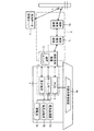
図1は実施例における自動検針回線網および宅内回線網の接続構成を示す説明図である。
図1において、1は電子式の電力量検針装置としての検針端末装置であり、各家庭に設置され、各家庭内の消費電力量や発電力量等(以下、「電力量」という。)を計量するものである。この検針端末装置1は、後述する通信ユニット10を搭載し、上位回線網および下位回線網における無線通信が可能になっている。
FIG. 1 is an explanatory diagram showing a connection configuration of an automatic meter-reading network and a residential network in the embodiment.
In FIG. 1,
また、検針端末装置1は、他の検針端末装置1aや検針端末装置1bとの間で相互に多段階通信制御を行うマルチホップ通信制御を行って中継器1cとの間で相互に通信を行い、また中継器1cとの間で直接相互に通信を行なう1対1通信制御を行って、その中継器1cを介して図示しない電力量値を収集するサーバや後述する宅内データ管理サーバ等と通信可能になっている。
The meter-
なお、検針端末装置1は、電力量だけでなく、ガス、または水道等の計量情報を計量するものであっても良く、また電力量、ガス、および水道のうち、いずれかひとつを計量し、その他の計量情報を、他の装置から受信して送信するものであっても良く、さらに電力量、ガス、および水道のうちいずれか2以上を計量するものであっても良い。
The meter-
2は上位装置としての宅内データ管理サーバであり、各家庭に設置された検針端末装置1と通信可能に接続され、検針端末装置1から受信した消費電力量や発電力量等の電力量値に基づいて各家庭における発電量の増減を制御する指示や各家庭を識別する識別情報であるユーザID等を当該検針端末装置1へ送信する。
Reference numeral 2 denotes a home data management server as a host device, which is communicably connected to the meter-
3は上位回線網としての自動検針回線網であり、各検針端末装置1(検針端末装置1a、検針端末装置1bや中継器1cを含む)間の通信を可能にする回線網である。なお、本実施例では、自動検針回線網3を無線回線網として説明するものとする。また、宅内データ管理サーバ2は、中継器1cと有線の通信回線で接続されているものとして説明するが、それに限られることなく、中継器1cと自動検針回線網3等の無線の通信回線で接続されていても良い。
4はPCS(Power Conditioning System)であり、各家庭に設置され、太陽光発電装置4aによる発電量や電力系統に出力する電力量を制御するものである。このPCS4は、下位回線網を介して検針端末装置1と通信可能になっており、検針端末装置1で計量された電力量の値をその検針端末装置1から受信し、受信した電力量の値に基づいて太陽光発電装置4aによる発電量や電力系統に出力する電力量を制御する。また、PCS4は、検針端末装置1を介して上位装置としてのサーバから受信した指示に基づいて太陽光発電装置4aによる発電量や電力系統に出力する電力量を制御する。
4 is a PCS (Power Conditioning System), which is installed in each home and controls the amount of power generated by the solar
5はホームサーバであり、各家庭に設置され、電気給湯器5a、電気自動車充電装置5b、蓄電池5c等へ供給する電力(例えば、電気給湯器5a、電気自動車充電装置5b、蓄電池5c等への電源供給およびその停止、およびそれらへ供給する電力量)を制御するものである。このホームサーバ5は、下位回線網を介して検針端末装置1と通信可能になっており、検針端末装置1から受信した指示に基づいてPCS4から入力する電力と電力系統から入力する電力とを切替える制御を行う。
6は表示端末であり、家庭内の消費電力量および発電量、電力系統に出力した電力量の合計値や、家庭内の消費電力量および発電量、電力系統に出力した電力量のそれぞれの電力量値等を表示する端末である。この表示端末6は、下位回線網を介して検針端末装置1と通信可能になっており、検針端末装置1から受信した指示や操作者の操作により家庭内の消費電力量および発電量、電力系統に出力した電力量の合計値や、家庭内の消費電力量および発電量、電力系統に出力した電力量等のそれぞれの電力量値等を表示および表示内容の切替を行う。
7は下位回線網としての宅内回線網であり、各家庭に設置された検針端末装置1、PCS4、ホームサーバ5、および表示端末6等の間の通信を可能にする回線網である。
なお、本実施例では、宅内回線網7を無線回線網として説明するものとする。また、宅内回線網7に接続される装置を検針端末装置1、PCS4、ホームサーバ5、および表示端末6としたが、それに限られるものでなく、各家庭用電気製品を接続するようにしても良い。
In the present embodiment, the
また、検針端末装置1は、図6に示すように宅内回線網7に接続されたガスメータ61や水道メータ等と接続し、各種計量情報を通信するようにしても良い。このとき、ガスメータ61や水道メータ等は、蓄電池を内蔵して稼働するものであっても良く、商用電源等から電源を得て稼動するものであっても良い。
Moreover, the meter-
さらに、検針端末装置1、PCS4、ホームサーバ5、および表示端末6等のそれぞれの装置は、1台の装置との間で相互に通信を行なう1対1の通信制御、および多段階通信制御であるマルチホップ通信制御、またはそのいずれか一方の通信制御を行う。このマルチホップ通信制御を行うことにより、装置間の距離や遮蔽物、障害物等による無線通信への影響を排除して通信可能になっている。
Furthermore, each device such as the meter-
またさらに、検針端末装置1、PCS4、ホームサーバ5、表示端末6、電気給湯器5a、および電気自動車充電装置5b等のそれぞれの装置は、太陽光発電装置4aや電力系統から供給される電力が不足や遮断等されても通信が可能になるように、蓄電池を備えるようにしても良い。
さらに、検針端末装置1は、図示しない上位サーバ等から受信した指示にしたがって宅内へ供給する全電力を開通/閉塞する開閉器を備えている。
Furthermore, each device such as the meter
Furthermore, the meter-
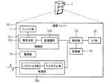
図2は実施例における通信ユニットの構成を示すブロック図である。
図2において、10は通信ユニットであり、検針端末装置1に搭載され、図1に示す自動検針回線網3および宅内回線網7における無線通信の制御を行うものである。
通信ユニット10は、アンテナ部11、無線部12、I/F(インターフェース)部13、記憶部14、制御部15、および各部に電力を供給する電源部16等により構成されている。
FIG. 2 is a block diagram showing the configuration of the communication unit in the embodiment.
In FIG. 2,
The
通信部としての無線部12は、アンテナ部11に接続された高周波部121と、高周波部121に接続された変復調部122とにより構成されている。この無線部12は、送信するデータを変復調部122で変調し、その変調された信号に基づいて高周波部121が所定の周波数の電波を生成し、アンテナ部11を介してその電波を発信する。また、アンテナ部11を介して高周波部121で受信した電波は、変復調部122で電気信号に変換されて受信データが生成される。
The
I/F部13は、有線通信を行うものであり、例えばUSB(Universal Serial Bus)等の有線通信回線により接続された保守用のパーソナルコンピュータ等との間の通信制御を行うものである。このI/F部13に接続された保守用のパーソナルコンピュータ等により、通信ユニット10を含む検針端末装置1に記憶された情報等を読出し、また検針端末装置1に各種設定情報等を設定することができるようになっている。
The I /
記憶部14は、揮発性メモリや不揮発性メモリ等により構成され、通信ユニット10全体の動作を制御する制御プログラムや無線通信制御を行う上で必要な各種制御情報等を記憶するものである。
The
制御部15は、演算手段および制御手段としてのCPU(Central Processing Unit)により構成され、記憶部14に記憶された制御プログラムに基づいて無線部12を含む通信ユニット10全体の動作を制御するものである。
制御部15は、無線部12を制御して自動検針回線網3および宅内回線網7で使用される周波数を同一なものとし、自動検針回線網3および宅内回線網7で送受信される伝送情報としての伝送データフレーム内の回線網識別情報としてのネットワークIDおよびアドレス(機器ID)により回線網および送受信先を決定するものとする。
The
The
このように通信ユニット10は、ひとつの無線部12で自動検針回線網3との間の無線通信と、宅内回線網7との間の無線通信とを行う。
なお、制御部15は、無線部12を制御することにより高周波部121の所定の周波数帯域内での使用チャネルを時分割で切替えて自動検針回線網3と、宅内回線網7とを切替えてもよい。
As described above, the
The
また、トークンにより送信装置を制御し、さらにビーコンにより送信装置と受信装置とのデータリンクを確立して自動検針回線網3と、宅内回線網7とを切替えるようにしても良い。さらに、自動検針回線網3および宅内回線網7の通信回数を予め決定しておき、自動検針回線網3における所定回数の通信が終了した後、宅内回線網7における通信を行い、または宅内回線網7における所定回数の通信が終了した後、自動検針回線網3における通信を行い、自動検針回線網3と、宅内回線網7とを切替えるようにしても良い。またさらに、制御部15により生成したランダムタイムにしたがって自動検針回線網3と、宅内回線網7とを切替えるようにしても良い。
また、検針端末装置1の通信ユニット10以外の構成は本発明に直接関係しないため、その説明を省略する。
Alternatively, the transmission device may be controlled by a token, and a data link between the transmission device and the reception device may be established by a beacon to switch between the automatic meter-reading
Further, since the configuration other than the
図3は実施例における通信ユニットの機能構成を示すブロック図である。
図3において、通信ユニット10の機能は、無線通信部21、伝送制御部22、上位ネットワーク制御部23a、下位ネットワーク制御部23b、自動検針アプリケーション部24a、宅内アプリケーション部24bにより構成されている。なお、これらの機能は、図2に示す制御部15によって制御される。
無線通信部21は物理層の通信制御を行い、伝送制御部22はデータリンク層の通信制御、例えば通信相手との通信路を確保し、また送受信されるデータの誤り検出等の通信制御を行う。
FIG. 3 is a block diagram illustrating a functional configuration of the communication unit in the embodiment.
In FIG. 3, the function of the
The
上位ネットワーク制御部23aは、図1に示す自動検針回線網3におけるネットワーク層の通信制御を行い、各検針端末装置1のマルチホップ通信制御や1対1通信制御等を行う。
下位ネットワーク制御部23bは、図1に示す宅内回線網7におけるネットワーク層の通信制御を行い、検針端末装置1と宅内の各装置との間の1対1の通信制御または検針端末装置1と宅内の各装置との間でのマルチホップ通信制御等を行う。
The host
The lower
自動検針アプリケーション部24aは、図1に示す自動検針回線網3における図示しない上位サーバとの間で通信を行い、例えば宅内の使用電力量値等を当該上位サーバへ送信し、また上位サーバから受信した制御情報や表示端末等から受信した要求にしたがって宅内の使用電力量を検針する。
また、自動検針アプリケーション部24aは、図示しない上位サーバ等から受信した指示にしたがって開閉器を制御して宅内への電力供給(開通)とその電力供給の遮断(閉塞)とを切替える。
The automatic meter
Further, the automatic meter
宅内アプリケーション部24bは、図1に示す宅内回線網7に接続されたPCS4、ホームサーバ5、および表示端末6等の各装置との間および図1に示す自動検針回線網3に接続された図示しない上位サーバとの間で通信を行い、上位サーバから受信した情報を宅内回線網7に接続された各装置へ送信して中継し、各装置から各種情報を受信した情報を上位サーバへ送信して中継する。また、計量器から宅内の使用電力量値を取得し、その宅内の使用電力量値を宅内回線網7に接続された各装置へ送信する。
The in-
図4は実施例における伝送データ形式を示す説明図である。図4(a)は自動検針回線網における伝送データの形式であり、図4(b)は宅内回線網における伝送データの形式である。なお、本伝送データ形式は例示であり、この伝送データ形式に限定されるものではない。 FIG. 4 is an explanatory diagram showing a transmission data format in the embodiment. FIG. 4A shows the format of transmission data in the automatic meter-reading network, and FIG. 4B shows the format of transmission data in the home network. Note that this transmission data format is an example, and the present invention is not limited to this transmission data format.
図4(a)において、自動検針回線網で送受信される伝送情報としての伝送データ30は、伝送ヘッダ31と、データヘッダ32と、データ33とから構成されている。
伝送ヘッダ31は、図3に示す伝送制御部22および上位ネットワーク制御部23aにより参照される領域である。この伝送ヘッダ31には、本伝送データ30が送受信される回線網を識別するための回線網識別情報としてのネットワークID311が含まれており、上位ネットワーク制御部23aはネットワークID311を参照し、そのネットワークID311が自動検針回線網を示す情報である場合、本伝送データ30を自動検針回線網内で通信するものとして扱う。
In FIG. 4A,
The transmission header 31 is an area referred to by the transmission control unit 22 and the upper
なお、本実施例では、上位ネットワーク制御部23aが回線網識別情報としてのネットワークID311を参照するものとしたが、伝送制御部22がネットワークID311を参照するようにしても良く、また伝送ヘッダ31に、伝送制御部22および上位ネットワーク制御部23aのそれぞれが参照する別個の回線網識別情報を含ませるようにしても良い。
データヘッダ32は、データ33のデータ属性等を示す情報であり、データ33は検針端末装置で計量された電力量値や各装置への指令情報等である。このデータヘッダ32およびデータ33は図3に示す自動検針アプリケーション部24aにより参照、処理される。
In this embodiment, the upper
The
また、図4(b)において、宅内回線網で送受信される伝送情報としての伝送データ40は、伝送ヘッダ41と、データヘッダ42と、データ43とから構成されている。
伝送ヘッダ41は、図3に示す伝送制御部22および下位ネットワーク制御部23bにより参照される領域である。この伝送ヘッダ41には、本伝送データ40が送受信される回線網を識別するための回線網識別情報としてのネットワークID411が含まれており、下位ネットワーク制御部23bはネットワークID411を参照し、そのネットワークID411が宅内回線網を示す情報である場合、本伝送データ40を宅内回線網内で通信するものとして扱う。
In FIG. 4B,
The
なお、本実施例では、下位ネットワーク制御部23bが回線網識別情報としてのネットワークID411を参照するものとしたが、伝送制御部22がネットワークID411を参照するようにしても良く、また伝送ヘッダ41に、伝送制御部22および下位ネットワーク制御部23bのそれぞれが参照する別個の回線網識別情報を含ませるようにしても良い。
In this embodiment, the lower
データヘッダ42は、データ43のデータ属性等を示す情報であり、データ43は検針端末装置で計量された電力量値や各装置への指令情報等である。このデータヘッダ42およびデータ43は図3に示す宅内アプリケーション部24bにより参照、処理される。
このように、自動検針回線網における伝送データ30の伝送ヘッダ31および宅内回線網における伝送データ40の伝送ヘッダ41にネットワークIDを含ませることにより、図1に示す自動検針回線網3と、宅内回線網7とにおいて通信される伝送データを分離することができるようになる。
The data header 42 is information indicating data attributes of the
Thus, by including the network ID in the transmission header 31 of the
なお、伝送データ30の伝送ヘッダ31に自動検針回線網から宅内回線網へ情報を送信する指令を含ませることができ、また、伝送データ40の伝送ヘッダ41に宅内回線網から自動検針回線網へ情報を送信する指令を含ませることができ、この指令を含んでいる場合、図3に示す上位ネットワーク制御部23aまたは下位ネットワーク制御部23bにより伝送ヘッダ31、41の変換を行い、自動検針回線網から宅内回線網へ、または宅内回線網から自動検針回線網へ情報を送信することができる。
The transmission header 31 of the
また、伝送データ30のデータ33に自動検針回線網から宅内回線網へ情報を送信する指令を含ませることができ、また、伝送データ40のデータ43に宅内回線網から自動検針回線網へ情報を送信する指令を含ませることができ、この指令を含んでいる場合、図3に示す自動検針アプリケーション部24aまたは宅内アプリケーション部24bにより伝送データ30、40の変換を行い、自動検針回線網から宅内回線網へ、または宅内回線網から自動検針回線網へ情報を送信することができる。
In addition, the data 33 of the
上述した構成の作用について、図5の実施例における自動検針回線網および宅内回線網での無線通信の処理の流れを示すブロック図の図中Sで表すステップに従って図1および図2を参照しながら説明する。なお、本実施例では、ホームサーバ5を宅内回線網7で通信可能にする例を説明する。
Regarding the operation of the above-described configuration, referring to FIG. 1 and FIG. 2 according to the step represented by S in the block diagram showing the flow of processing of wireless communication in the automatic meter line network and the home network in the embodiment of FIG. explain. In this embodiment, an example will be described in which the
S1:宅内データ管理サーバ2を管理する電力会社等は、各家庭に家庭識別情報としてのユーザIDおよびそのユーザIDに関連付けられた初期パスワード(初期PW)を送付する。
ここで、宅内データ管理サーバ2は、データベースに検針端末装置ID、ユーザIDおよび初期パスワードを記憶するものとする。
S1: A power company or the like that manages the home data management server 2 sends a user ID as home identification information and an initial password (initial PW) associated with the user ID to each home.
Here, the home data management server 2 shall memorize | store meter-reading terminal device ID, user ID, and an initial password in a database.
S2:ユーザIDおよび初期パスワードを受取ったユーザは、インターネット9等の通信回線に接続されたパーソナルコンピュータ8等を利用して受取ったユーザIDおよび初期パスワードを入力し、認証を行って宅内データ管理サーバ2へアクセスし、ユーザが設定するパスワード(ユーザPW)、および宅内のホームサーバ5を識別するための機器識別情報としての機器IDを入力して登録するものとする。
パーソナルコンピュータ8等は入力されたユーザID、パスワード(ユーザPW)、および機器IDを宅内データ管理サーバ2へ送信する。
S2: The user who has received the user ID and the initial password inputs the user ID and the initial password received using the
The
S3:宅内データ管理サーバ2は、受信したユーザIDに基づいてデータベースを検索する。
S4:宅内データ管理サーバ2は、当該ユーザIDに関連付けてパスワードとともに機器IDをデータベースに記憶する。したがって、宅内データ管理サーバ2のデータベースには、検針端末装置ID(メータID)およびユーザIDに関連付けてパスワード(ユーザPW)と機器IDとが記憶される。
S3: The home data management server 2 searches the database based on the received user ID.
S4: The home data management server 2 stores the device ID together with the password in the database in association with the user ID. Therefore, the database of the home data management server 2 stores the password (user PW) and the device ID in association with the meter reading terminal device ID (meter ID) and the user ID.
S5:宅内データ管理サーバ2は、自動検針回線網3を介してデータベースに記憶した検針端末装置IDの検針端末装置1宛てに機器IDを送信する。このとき、宅内データ管理サーバ2から検針端末装置1宛てに送信される伝送データは、図4に示す伝送ヘッダ31のネットワークID311に自動検針回線網を表す情報が格納され、データ33に機器ID、また伝送ヘッダ31に送信先の検針端末装置1のアドレスを含むものとする。
S6:検針端末装置1の通信ユニット10の制御部15は、自動検針回線網3を介して宅内データ管理サーバ2から受信した機器IDを受信し、自己の検針端末装置IDとともに受信した機器IDを記憶部14に記憶させ、保存する。
S5: The home data management server 2 transmits the device ID to the meter
S6: The
S7:一方、検針端末装置1との間で無線通信が確立していないホームサーバ5は、宅内回線網7を介して記憶部に記憶されている機器IDを周期的に検針端末装置1へブロードキャスト送信する。このとき、ホームサーバ5から検針端末装置1宛てに送信される伝送データは、図4に示す伝送ヘッダ41のネットワークID411に宅内回線網を表す情報が格納され、また伝送ヘッダ41に機器IDを含むものとする。
S7: On the other hand, the
S8:検針端末装置1の通信ユニット10の制御部15(伝送制御部22)は、宅内回線網7を介して機器IDをホームサーバ5から受信し、受信した機器IDが記憶部に記憶されているかの認証を行う。
なお、本実施例では、機器IDの認証を検針端末装置1の通信ユニット10で行なうようにしたが、ホームサーバ5が、検針端末装置1の通信ユニット10から機器IDを受信し、受信した機器IDが記憶部に記憶されているかの認証を行うようにしても良い。
S8: The control unit 15 (transmission control unit 22) of the
In the present embodiment, the device ID is authenticated by the
S9:通信ユニット10の制御部15(伝送制御部22)は、受信した機器IDが記憶部に記憶されていると判定、すなわち当該機器IDが登録されていると判定すると宅内回線網7を介してホームサーバ5との無線通信を許可する。
一方、通信ユニット10の制御部15(伝送制御部22)は、受信した機器IDが記憶部に記憶されていないと判定、すなわち当該機器IDが登録されていないと判定すると宅内回線網7を介してホームサーバ5との無線通信を許可せず、以降のホームサーバ5との無線通信を禁止する。
S9: When the control unit 15 (transmission control unit 22) of the
On the other hand, if the control unit 15 (transmission control unit 22) of the
以上説明したように、本実施例では、通信ユニットおよびその通信ユニットを搭載する検針端末装置を小型化することができ、各家庭に容易に設置することができるという効果が得られる。
また、通信ユニットおよびその通信ユニットを搭載する検針端末装置の部品点数を削減することができ、低価格化することもできるという効果が得られる。
さらに、宅内回線網に水道メータやガスメータ等の各種計量情報を検針する検針装置を接続することにより、各種計量情報の管理を容易にすることができるという効果が得られる。
As described above, in this embodiment, the communication unit and the meter-reading terminal device on which the communication unit is mounted can be reduced in size, and an effect that it can be easily installed in each home is obtained.
Further, it is possible to reduce the number of parts of the communication unit and the meter-reading terminal device on which the communication unit is mounted, and it is possible to reduce the price.
Furthermore, by connecting a meter-reading device for metering various pieces of measurement information such as a water meter and a gas meter to the home network, it is possible to easily manage various pieces of measurement information.
なお、本実施例では、自動検針回線網および宅内回線網の双方の回線網は無線回線網として説明したが、自動検針回線網および宅内回線網の双方またはいずれか一方は、無線回線網または有線回線網のどちらであっても良く、また無線通信および有線通信が混在した回線網としても良い。有線回線網としては、LAN(Local Area Network)、光通信、電力線搬送通信等が挙げられる。 In the present embodiment, both the automatic meter-reading network and the home network are described as wireless networks, but both the automatic meter-reading network and the home network are either a wireless network or a wired network. Either a line network or a line network in which wireless communication and wired communication are mixed may be used. Examples of the wired network include LAN (Local Area Network), optical communication, power line carrier communication, and the like.
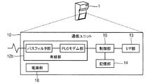
例えば、自動検針回線網および宅内回線網の双方の回線網を無線通信および有線通信が混在した回線網とした場合、図7に示すように無線通信を通信ユニット10の無線部12で行い、有線通信を有線部12aで行うようにする。なお、図7の有線部12aは、パスフィルタ部およびPLCモデム部等を備え、電力線搬送通信を行う例を示している。
また、自動検針回線網および宅内回線網の双方の回線網を有線回線網とした場合、図8に示すように有線通信を有線部12bで行うようにする。なお、図8の有線部12bは、パスフィルタ部およびPLCモデム部等を備え、電力線搬送通信を行う例を示している。
For example, when both the automatic meter-reading line network and the home line network are line networks in which wireless communication and wired communication are mixed, wireless communication is performed by the
Further, when both the automatic meter-reading network and the home network are wired networks, wired communication is performed by the
1 検針端末装置
2 宅内データ管理サーバ
3 自動検針回線網
4 PCS
5 ホームサーバ
6 表示端末
7 宅内回線網
10 通信ユニット
11 アンテナ部
12 無線部
13 I/F部
14 記憶部
15 制御部
16 電源部
21 無線通信部
22 伝送制御部
23a 上位ネットワーク制御部
23b 下位ネットワーク制御部
24a 自動検針アプリケーション部
24b 宅内アプリケーション部
61 ガスメータ
62 水道メータ
1 Meter reading terminal device 2 Home
DESCRIPTION OF
Claims (8)
前記無線部は、伝送情報に含まれる回線網識別情報に基づいて、前記自動検針回線網との間の無線通信と、前記宅内回線網との間の無線通信とを分けて行うことを特徴とする通信ユニット。 The communication unit of claim 1,
The wireless unit performs wireless communication with the automatic metering line network and wireless communication with the home line network separately based on line network identification information included in transmission information. Communication unit.
前記自動検針回線網を無線回線網とし、
前記宅内回線網を無線回線網とし、
前記無線部は、前記自動検針回線網との間の無線通信と、前記宅内回線網との間の無線通信とを行うことを特徴とする通信ユニット。 The communication unit of claim 1 or claim 2,
The automatic meter reading network is a wireless network,
The home network is a wireless network,
The wireless unit performs wireless communication with the automatic meter-reading network and wireless communication with the home network.
前記自動検針回線網を有線通信および無線通信が混在した回線網とし、
前記宅内回線網を有線通信および無線通信が混在した回線網とし、
前記無線部は、前記自動検針回線網との間の無線通信と、前記宅内回線網との間の無線通信とを行うことを特徴とする通信ユニット。 The communication unit of claim 1 or claim 2,
The automatic meter reading line network is a line network in which wired communication and wireless communication are mixed,
The home network is a network in which wired communication and wireless communication are mixed,
The wireless unit performs wireless communication with the automatic meter-reading network and wireless communication with the home network.
前記宅内回線網に接続された宅内装置を識別する機器識別情報を予め記憶する記憶部と、
前記宅内回線網に接続された宅内装置から機器識別情報を受信し、受信した前記機器識別情報が、前記記憶部に記憶されている機器識別情報と一致したとき、以降の宅内回線網における無線通信を許可する制御部とを備えたことを特徴とする通信ユニット。 The communication unit according to any one of claims 1 to 4,
A storage unit that stores in advance device identification information for identifying a home device connected to the home network;
When the device identification information is received from the home device connected to the home network, and the received device identification information matches the device identification information stored in the storage unit, wireless communication in the home network thereafter A communication unit.
前記記憶部に記憶する機器識別情報は、前記自動検針回線網に接続された上位装置から受信した機器識別情報としたことを特徴とする通信ユニット。 The communication unit of claim 5,
The device identification information stored in the storage unit is device identification information received from a host device connected to the automatic meter-reading network.
請求項1から請求項6のいずれか1項に記載の通信ユニットを搭載したことを特徴とする検針端末装置。 In the meter-reading terminal device that measures various measurement information,
A meter-reading terminal device comprising the communication unit according to any one of claims 1 to 6.
前記検針端末装置は、電力量を検針することを特徴とする検針端末装置。 In the meter-reading terminal device according to claim 7,
The meter-reading terminal device measures the amount of electric power.
Priority Applications (1)
| Application Number | Priority Date | Filing Date | Title |
|---|---|---|---|
| JP2011042117A JP2012182519A (en) | 2011-02-28 | 2011-02-28 | Communication unit and meter-reading terminal device |
Applications Claiming Priority (1)
| Application Number | Priority Date | Filing Date | Title |
|---|---|---|---|
| JP2011042117A JP2012182519A (en) | 2011-02-28 | 2011-02-28 | Communication unit and meter-reading terminal device |
Publications (1)
| Publication Number | Publication Date |
|---|---|
| JP2012182519A true JP2012182519A (en) | 2012-09-20 |
Family
ID=47013379
Family Applications (1)
| Application Number | Title | Priority Date | Filing Date |
|---|---|---|---|
| JP2011042117A Pending JP2012182519A (en) | 2011-02-28 | 2011-02-28 | Communication unit and meter-reading terminal device |
Country Status (1)
| Country | Link |
|---|---|
| JP (1) | JP2012182519A (en) |
Cited By (1)
| Publication number | Priority date | Publication date | Assignee | Title |
|---|---|---|---|---|
| JP2015032945A (en) * | 2013-08-01 | 2015-02-16 | ネッツエスアイ東洋株式会社 | Automatic meter reading system and plc modem used for the same |
Citations (7)
| Publication number | Priority date | Publication date | Assignee | Title |
|---|---|---|---|---|
| JPH098933A (en) * | 1995-06-23 | 1997-01-10 | Matsushita Electric Ind Co Ltd | Automatic metering system |
| JP2000101578A (en) * | 1998-09-21 | 2000-04-07 | Matsushita Electric Ind Co Ltd | Radio network system |
| JP2000278435A (en) * | 1999-03-23 | 2000-10-06 | Tokyo Gas Co Ltd | Isdn communication system and communicating method |
| JP2002063945A (en) * | 2000-08-18 | 2002-02-28 | Toyo Keiki Co Ltd | Check method of cell voltage of communication device |
| JP2003256969A (en) * | 2002-03-06 | 2003-09-12 | Okuto Kikaku:Kk | Automatic metering system of single power or common with gas/water |
| JP2003274038A (en) * | 2002-03-19 | 2003-09-26 | Osaka Gas Co Ltd | Common metering system, master unit for metering, and metering method for gas meter and watt-hour meter |
| JP2009010650A (en) * | 2007-06-27 | 2009-01-15 | Panasonic Corp | Device management system, center device, master receiving device, slave receiving devices, and device management method |
-
2011
- 2011-02-28 JP JP2011042117A patent/JP2012182519A/en active Pending
Patent Citations (7)
| Publication number | Priority date | Publication date | Assignee | Title |
|---|---|---|---|---|
| JPH098933A (en) * | 1995-06-23 | 1997-01-10 | Matsushita Electric Ind Co Ltd | Automatic metering system |
| JP2000101578A (en) * | 1998-09-21 | 2000-04-07 | Matsushita Electric Ind Co Ltd | Radio network system |
| JP2000278435A (en) * | 1999-03-23 | 2000-10-06 | Tokyo Gas Co Ltd | Isdn communication system and communicating method |
| JP2002063945A (en) * | 2000-08-18 | 2002-02-28 | Toyo Keiki Co Ltd | Check method of cell voltage of communication device |
| JP2003256969A (en) * | 2002-03-06 | 2003-09-12 | Okuto Kikaku:Kk | Automatic metering system of single power or common with gas/water |
| JP2003274038A (en) * | 2002-03-19 | 2003-09-26 | Osaka Gas Co Ltd | Common metering system, master unit for metering, and metering method for gas meter and watt-hour meter |
| JP2009010650A (en) * | 2007-06-27 | 2009-01-15 | Panasonic Corp | Device management system, center device, master receiving device, slave receiving devices, and device management method |
Cited By (1)
| Publication number | Priority date | Publication date | Assignee | Title |
|---|---|---|---|---|
| JP2015032945A (en) * | 2013-08-01 | 2015-02-16 | ネッツエスアイ東洋株式会社 | Automatic meter reading system and plc modem used for the same |
Similar Documents
| Publication | Publication Date | Title |
|---|---|---|
| CN103202034B (en) | The resource metering system consumed for Intelligent Energy and the method using such system | |
| JP5866580B2 (en) | Remote meter reading system, slave station, master station | |
| US8863228B2 (en) | Energy management apparatus and energy management system | |
| US9518838B2 (en) | Slave suitable for energy management systems and energy management system | |
| US20150035682A1 (en) | Slave suitable for energy management systems and energy management system | |
| JP2014072561A (en) | Home electric appliance remote monitoring system | |
| US10879957B2 (en) | Device, system and method for selectively receiving data broadcast in a network | |
| Tariq et al. | Smart grid standards for home and building automation | |
| CN110730247B (en) | Communication control system based on power line carrier | |
| JP2016524402A (en) | Wireless power control and measurements | |
| JP2015012447A (en) | Communication system and communication device | |
| JP2018117455A (en) | Power consumption amount monitoring device | |
| EP3053308B1 (en) | In-premises management of home area networks | |
| JP2012182519A (en) | Communication unit and meter-reading terminal device | |
| JP6155530B2 (en) | Communication system and communication equipment | |
| WO2015087501A1 (en) | Meter-reader management device | |
| JP2013187848A (en) | Communication system and communication device | |
| KR20170117794A (en) | Apparatus for integrated metering based on international standard protocol and method for the same | |
| US20120307708A1 (en) | Repeater pass-through messaging | |
| KR20170134247A (en) | Method of open wireless environment channel configuration in automatic meter reading system using an universal subscriber identify module and apparatus for the same | |
| US20180052988A1 (en) | Information processing system, information processing method, and program | |
| CN103703721B (en) | The home system of connection is accessed for managing internet | |
| JP2017050970A (en) | Relay device and energy management system | |
| GÖKBAYRAK et al. | Wireless sensor network-based extension to KNX home automation system | |
| Saleh et al. | Wireless home automation system based on microcontroller |
Legal Events
| Date | Code | Title | Description |
|---|---|---|---|
| A621 | Written request for application examination |
Free format text: JAPANESE INTERMEDIATE CODE: A621 Effective date: 20131025 |
|
| A977 | Report on retrieval |
Free format text: JAPANESE INTERMEDIATE CODE: A971007 Effective date: 20140515 |
|
| A131 | Notification of reasons for refusal |
Free format text: JAPANESE INTERMEDIATE CODE: A131 Effective date: 20140520 |
|
| A02 | Decision of refusal |
Free format text: JAPANESE INTERMEDIATE CODE: A02 Effective date: 20140930 |