JP2012179956A - Occupant protection apparatus and occupant protection method - Google Patents
Occupant protection apparatus and occupant protection method Download PDFInfo
- Publication number
- JP2012179956A JP2012179956A JP2011042649A JP2011042649A JP2012179956A JP 2012179956 A JP2012179956 A JP 2012179956A JP 2011042649 A JP2011042649 A JP 2011042649A JP 2011042649 A JP2011042649 A JP 2011042649A JP 2012179956 A JP2012179956 A JP 2012179956A
- Authority
- JP
- Japan
- Prior art keywords
- airbag
- occupant
- vehicle
- chamber
- chest
- Prior art date
- Legal status (The legal status is an assumption and is not a legal conclusion. Google has not performed a legal analysis and makes no representation as to the accuracy of the status listed.)
- Pending
Links
- 238000000034 method Methods 0.000 title claims description 15
- 230000001681 protective effect Effects 0.000 claims 2
- 230000035939 shock Effects 0.000 abstract 1
- 239000004744 fabric Substances 0.000 description 10
- 230000001965 increasing effect Effects 0.000 description 6
- 206010061386 Chest injury Diseases 0.000 description 4
- 208000029224 Thoracic injury Diseases 0.000 description 4
- 210000001217 buttock Anatomy 0.000 description 4
- 238000009958 sewing Methods 0.000 description 4
- 238000001514 detection method Methods 0.000 description 1
- 238000010586 diagram Methods 0.000 description 1
- 230000002708 enhancing effect Effects 0.000 description 1
- 239000002360 explosive Substances 0.000 description 1
- 239000005357 flat glass Substances 0.000 description 1
- 230000002093 peripheral effect Effects 0.000 description 1
- 238000000638 solvent extraction Methods 0.000 description 1
- 239000002759 woven fabric Substances 0.000 description 1
Images


Classifications
-
- B—PERFORMING OPERATIONS; TRANSPORTING
- B60—VEHICLES IN GENERAL
- B60R—VEHICLES, VEHICLE FITTINGS, OR VEHICLE PARTS, NOT OTHERWISE PROVIDED FOR
- B60R21/00—Arrangements or fittings on vehicles for protecting or preventing injuries to occupants or pedestrians in case of accidents or other traffic risks
- B60R21/02—Occupant safety arrangements or fittings, e.g. crash pads
- B60R21/16—Inflatable occupant restraints or confinements designed to inflate upon impact or impending impact, e.g. air bags
- B60R21/23—Inflatable members
- B60R21/231—Inflatable members characterised by their shape, construction or spatial configuration
- B60R21/23138—Inflatable members characterised by their shape, construction or spatial configuration specially adapted for side protection
-
- B—PERFORMING OPERATIONS; TRANSPORTING
- B60—VEHICLES IN GENERAL
- B60R—VEHICLES, VEHICLE FITTINGS, OR VEHICLE PARTS, NOT OTHERWISE PROVIDED FOR
- B60R21/00—Arrangements or fittings on vehicles for protecting or preventing injuries to occupants or pedestrians in case of accidents or other traffic risks
- B60R21/02—Occupant safety arrangements or fittings, e.g. crash pads
- B60R21/16—Inflatable occupant restraints or confinements designed to inflate upon impact or impending impact, e.g. air bags
- B60R21/23—Inflatable members
- B60R21/231—Inflatable members characterised by their shape, construction or spatial configuration
- B60R21/233—Inflatable members characterised by their shape, construction or spatial configuration comprising a plurality of individual compartments; comprising two or more bag-like members, one within the other
-
- B—PERFORMING OPERATIONS; TRANSPORTING
- B60—VEHICLES IN GENERAL
- B60R—VEHICLES, VEHICLE FITTINGS, OR VEHICLE PARTS, NOT OTHERWISE PROVIDED FOR
- B60R21/00—Arrangements or fittings on vehicles for protecting or preventing injuries to occupants or pedestrians in case of accidents or other traffic risks
- B60R21/02—Occupant safety arrangements or fittings, e.g. crash pads
- B60R21/16—Inflatable occupant restraints or confinements designed to inflate upon impact or impending impact, e.g. air bags
- B60R21/23—Inflatable members
- B60R21/231—Inflatable members characterised by their shape, construction or spatial configuration
- B60R21/23138—Inflatable members characterised by their shape, construction or spatial configuration specially adapted for side protection
- B60R2021/23146—Inflatable members characterised by their shape, construction or spatial configuration specially adapted for side protection seat mounted
-
- B—PERFORMING OPERATIONS; TRANSPORTING
- B60—VEHICLES IN GENERAL
- B60R—VEHICLES, VEHICLE FITTINGS, OR VEHICLE PARTS, NOT OTHERWISE PROVIDED FOR
- B60R21/00—Arrangements or fittings on vehicles for protecting or preventing injuries to occupants or pedestrians in case of accidents or other traffic risks
- B60R21/02—Occupant safety arrangements or fittings, e.g. crash pads
- B60R21/16—Inflatable occupant restraints or confinements designed to inflate upon impact or impending impact, e.g. air bags
- B60R21/23—Inflatable members
- B60R21/239—Inflatable members characterised by their venting means
Abstract
Description
本発明は、乗員保護装置及び乗員保護方法に関し、特に、一つのインフレータで複数のチャンバを形成することが可能なエアバッグを有し、このエアバッグを車両側壁と乗員との間で展開させることで、車両側壁への側面衝突(以下、単に側突という。)による衝撃から乗員を保護する乗員保護装置及び乗員保護方法に関する。 The present invention relates to an occupant protection device and an occupant protection method, and in particular, has an airbag capable of forming a plurality of chambers with a single inflator, and deploys the airbag between a vehicle side wall and an occupant. The present invention relates to an occupant protection device and an occupant protection method for protecting an occupant from an impact caused by a side collision with a vehicle side wall (hereinafter, simply referred to as a side collision).
従来、乗員保護装置は、一つのインフレータで一つのチャンバを形成するエアバッグを有し、このエアバッグを車両側壁と乗員との間で展開させることで、車両側壁への側突による衝撃から乗員を保護するものが一般的に知られている。 Conventionally, an occupant protection device has an airbag that forms one chamber with one inflator, and deploys the airbag between the vehicle side wall and the occupant, thereby preventing the occupant from an impact caused by a side collision on the vehicle side wall. Those that protect are generally known.
このような一つのインフレータで一つのチャンバを形成するエアバッグを有する乗員保護装置は、例えば、エアバッグの車両の幅方向における厚みを厚くすると、車両側壁と乗員との間で空間を確保することが可能になり、側突に対する乗員への安全性を高めることができるという利点がある。 Such an occupant protection device having an airbag that forms one chamber with one inflator, for example, secures a space between the vehicle side wall and the occupant when the thickness of the airbag in the width direction of the vehicle is increased. Is possible, and there is an advantage that the safety to the occupant against the side collision can be improved.
ここで、車両側壁と乗員との間の空間を確保することにより、側突に対する乗員への安全性を高めることができるとは、側突時に、車両側壁は車両の幅方向における車室側に変位するが、車両側壁と乗員との間でエアバッグを展開させることで、車両側壁を乗員に接触させないようにすることで、安全性を高めることをいう。 Here, by ensuring the space between the vehicle side wall and the occupant, safety to the occupant against a side collision can be improved. Although it is displaced, it means that safety is improved by deploying an airbag between the vehicle side wall and the occupant so that the vehicle side wall is not brought into contact with the occupant.
しかしながら、エアバッグの車両の幅方向における厚みを厚くすると、エアバッグの展開時に、エアバッグが車両側壁と乗員との間の空間に位置するドアアームレスト等にぶつかってしまい、車両側壁と乗員との間でエアバッグを確実に展開させる点について改善の余地があった。 However, if the thickness of the airbag in the width direction of the vehicle is increased, when the airbag is deployed, the airbag hits a door armrest or the like located in the space between the vehicle sidewall and the occupant, and the vehicle sidewall and occupant There was room for improvement in terms of deploying airbags reliably.
これに対し、エアバッグの車両の幅方向における厚みを薄くすると、エアバッグの展開時に、ドアアームレスト等にぶつかり難くなるものの、車両側壁と乗員との間で空間を確保する点については改善の余地があった。 On the other hand, if the thickness of the airbag in the width direction of the vehicle is reduced, it will be difficult to hit the door armrest when the airbag is deployed, but there is room for improvement in terms of securing a space between the vehicle sidewall and the occupant. was there.
ここで、エアバッグの展開時に、車両側壁と乗員との間でエアバッグを確実に展開させ、かつ、車両側壁と乗員との間で空間を確保することが可能なものとして、例えば、複数のサイドエアバッグ装置を用いることが考えられる。 Here, when the airbag is deployed, the airbag can be reliably deployed between the vehicle sidewall and the occupant, and a space can be secured between the vehicle sidewall and the occupant. It is conceivable to use a side airbag device.
しかしながら、複数のサイドエアバッグ装置を用いた場合、互いのエアバッグを展開させるタイミングを制御するための制御手段等が必要になり、構成が複雑になるという技術的課題がある。 However, when a plurality of side airbag devices are used, there is a technical problem that a control means for controlling the timing of deploying each other's airbag is required, and the configuration becomes complicated.
そして、このような制御手段等が必要になることで、コストを増大させてしまうという技術的課題がある。また、複数のサイドエアバッグ装置を用いた場合、互いのエアバッグが干渉してしまうという技術的課題がある。 And the necessity of such a control means has a technical problem of increasing costs. In addition, when a plurality of side airbag devices are used, there is a technical problem that the airbags interfere with each other.
このため、近年、乗員保護装置には、この乗員保護装置を簡易的な構成とするために、一つのインフレータで複数のチャンバを形成することが可能なエアバッグを有し、これら複数のチャンバを確実に展開させて車両側壁と乗員との間の空間を確保することが可能なものが求められている。 Therefore, in recent years, the occupant protection device has an airbag that can form a plurality of chambers with a single inflator in order to make the occupant protection device a simple configuration. There is a need for a device that can be surely deployed to secure a space between a vehicle side wall and an occupant.
そこで、乗員保護装置を簡易的な構成とするものとして、例えば、特許文献1には、高圧バッグと低圧バッグとを一つのインフレータにより展開させる際、高圧バッグを先に展開させ、その後低圧バッグを展開させることが可能なサイドエアバッグ装置が開示されている。
Therefore, as a simple configuration of the occupant protection device, for example, in
また、特許文献2には、アームレストの上方に向けて展開される上部チャンバと、アームレストの下方に向けて展開される下部チャンバとを有するサイドエアバッグ装置が開示されている。
しかしながら、上記特許文献1は、一つのインフレータで高圧バッグと低圧バッグとを展開させ、低圧バッグにより乗員の胸部付近を保護しているが、高圧バッグがドアアームレストにぶつかってしまう可能性が考えられる。このため、上記特許文献1は、高圧バッグを確実に展開させる点について改善の余地がある。
However, although the said
また、上記特許文献2は、上部チャンバと下部チャンバとで、アームレストにぶつからないように展開しているものの、乗員の胸部付近を保護するものではないため、車両側壁への側突による衝撃から乗員を保護する際の安全性を高める点について改善の余地がある。
Moreover, although the said
本発明の目的は、上記従来の実状に鑑みて、一つのインフレータで複数のチャンバを形成することが可能なエアバッグを有する乗員保護装置及び乗員保護方法に関し、車両側壁と乗員との間の空間を確保するとともに、乗員の胸部を保護することで、車両側壁への側突による衝撃から乗員を保護する際の安全性を高めることが可能な乗員保護装置及び乗員保護方法を提供することにある。 In view of the above-described conventional situation, an object of the present invention relates to an occupant protection device and an occupant protection method having an airbag capable of forming a plurality of chambers with a single inflator, and a space between a vehicle sidewall and an occupant. It is intended to provide an occupant protection device and an occupant protection method capable of enhancing safety when protecting an occupant from an impact caused by a side collision on a vehicle side wall by securing the occupant's chest. .
このような課題を解決するために、本発明に係る乗員保護装置は、一つのインフレータで複数のチャンバを形成することが可能なエアバッグを有し、当該エアバッグを車両側壁と乗員との間で展開させることで、上記車両側壁への衝突から上記乗員を保護するものであって、上記エアバッグは、複数の上記チャンバのうち、車両の上下方向におけるドアアームレストの上部及び下部で展開可能なドアアームレスト側チャンバと、上記車両の幅方向における上記ドアアームレスト側チャンバよりも車室側で、かつ、上記乗員の胸部付近で展開可能な胸部側チャンバと、を有して構成されている。 In order to solve such a problem, an occupant protection device according to the present invention has an airbag capable of forming a plurality of chambers with one inflator, and the airbag is disposed between a vehicle side wall and an occupant. The airbag can be deployed at the upper and lower portions of the door armrest in the vertical direction of the vehicle among the plurality of chambers. The door armrest side chamber, and a chest side chamber that is deployable near the passenger's chest and closer to the passenger compartment than the door armrest side chamber in the width direction of the vehicle are configured.
また、本発明に係る乗員保護装置は、一つのインフレータで複数のチャンバを形成することが可能なエアバッグを有し、当該エアバッグを車両側壁と乗員との間で展開させることで、上記車両側壁への衝突から上記乗員を保護するものであって、上記エアバッグは、複数の上記チャンバのうち、車両の幅方向におけるドアアームレストの車室側の面に向かって展開可能なドアアームレスト側チャンバと、上記車両の幅方向における上記ドアアームレスト側チャンバよりも車室側で、かつ、上記乗員の胸部付近で展開可能な胸部側チャンバとを有して構成されている。 In addition, an occupant protection device according to the present invention includes an airbag capable of forming a plurality of chambers with a single inflator, and deploys the airbag between the vehicle side wall and the occupant so that the vehicle The airbag protects the occupant from a collision with a side wall, and the airbag is a door armrest side chamber that can be deployed toward a vehicle side surface of the door armrest in the vehicle width direction among the plurality of chambers. And a chest side chamber that can be deployed in the vehicle compartment side of the door armrest side chamber in the width direction of the vehicle and in the vicinity of the chest of the occupant.
また、本発明に係る乗員保護装置の上記エアバッグは、上記インフレータにより上記ドアアームレスト側チャンバに供給される供給ガスの圧力が、当該車両側壁側チャンバ内で所定の圧力に達すると、上記ドアアームレスト側チャンバと胸部側チャンバとを連通する圧力弁を具備して構成されている。 Further, the airbag of the occupant protection device according to the present invention is configured so that the pressure of the supply gas supplied to the door armrest side chamber by the inflator reaches a predetermined pressure in the vehicle side wall chamber. A pressure valve is provided to communicate the side chamber and the chest side chamber.
また、本発明に係る乗員保護装置の上記エアバッグのドアアームレスト側チャンバは、上記ドアアームレストの上記上部を展開可能な上部チャンバと、上記ドアアームレストの上記下部を展開可能な下部チャンバと、を有して構成されている。 Further, the door armrest side chamber of the airbag of the occupant protection device according to the present invention has an upper chamber capable of deploying the upper part of the door armrest and a lower chamber capable of deploying the lower part of the door armrest. Configured.
このような課題を解決するために、本発明に係る乗員保護方法は、一つのインフレータで複数のチャンバを形成するエアバッグを車両側壁と乗員との間で展開させることで、上記車両側壁への衝突から上記乗員を保護し、複数の上記チャンバは、少なくとも一つの上記チャンバがドアアームレストの車両の上下方向における上部及び下部で展開し、少なくとも一つの上記チャンバが乗員の胸部を保護するように展開している。 In order to solve such a problem, an occupant protection method according to the present invention deploys an airbag forming a plurality of chambers with a single inflator between the vehicle side wall and the occupant, thereby The occupant is protected from a collision, and the plurality of chambers are deployed such that at least one of the chambers is deployed at the upper and lower portions of the door armrest in the vertical direction of the vehicle, and at least one of the chambers protects the occupant's chest. is doing.
本発明によれば、一つのインフレータで複数のチャンバを形成することが可能なエアバッグを有する乗員保護装置及び乗員保護方法に関し、車両側壁と乗員との間の空間を確保するとともに、乗員の胸部を保護することで、車両側壁への側突による衝撃から乗員を保護する際の安全性を高めることが可能な乗員保護装置及び乗員保護方法を提供することができる。 The present invention relates to an occupant protection device and an occupant protection method having an airbag capable of forming a plurality of chambers with a single inflator, as well as ensuring a space between a vehicle side wall and an occupant, and an occupant's chest. By protecting the vehicle, it is possible to provide an occupant protection device and an occupant protection method capable of improving safety when protecting an occupant from an impact caused by a side collision on the vehicle side wall.
以下、本発明の実施の形態について、図を用いて説明する。本発明の実施の形態であるサイドエアバッグ装置10は、一つのインフレータ11で複数のチャンバを形成することが可能なエアバッグ12を有し、このエアバッグ12をサイドドア20(車両側壁)と乗員との間で展開させることで、サイドドア20への側突による衝撃から乗員を保護するものである。
Hereinafter, embodiments of the present invention will be described with reference to the drawings. A
すなわち、本実施の形態のサイドエアバッグ装置10は、乗員保護装置に相当する。また、本実施の形態のサイドエアバッグ装置10により乗員を保護する方法は、乗員保護方法に相当する。
That is, the
(実施の形態1)
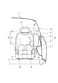
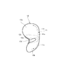
まず、本発明の一実施の形態であるサイドエアバッグ装置10を適用した車両5のサイドドア20及び車両用シート30について、図1及び図2を用いて説明する。図1は、本発明の一実施の形態であるサイドエアバッグ装置10を適用した車両5のサイドドア20及び車両用シート30を示し、サイドエアバッグ装置10のエアバッグ12が展開した状態を車両の前方側から模式的に示す前方面図である。
(Embodiment 1)
First, a
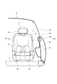
また、図2は、本発明の一実施の形態であるサイドエアバッグ装置10を適用した車両5のサイドドア20及び車両用シート30を示し、サイドエアバッグ装置10のエアバッグ12が展開した状態を車両の側方側から模式的に示す側方面図である。
2 shows the
図1及び図2に例示されるように、本実施の形態のサイドドア20は、このサイドドア20のフレームを構成するインナーパネル21及びアウターパネル22を備えて構成されている。
As illustrated in FIGS. 1 and 2, the
また、サイドドア20は、インナーパネル21とアウターパネル22との間に、インナーパネル21とアウターパネル22との間を車両5の上下方向で上下動可能な窓ガラス23を備えて構成されている。
The
そして、サイドドア20を構成するインナーパネル21の車両5の幅方向における車室側には、ドアトリム24が取り付けられている。このドアトリム24には、車両の幅方向における車室側に向かって突出するドアアームレスト25が配設されている。そして、ドアアームレスト25の車両5の幅方向における車室側には、乗員が着座するための車両用シート30が配設されている。
A
この車両用シート30は、乗員が着座するためのシートクッション31と、このシートクッション31の車両の前後方向における後端部に配置され、乗員が寄り掛かるためのシートバック32と、を備えて構成されている。また、車両用シート30は、車両の上下方向におけるシートバック32の上端部にヘッドレスト33を備えて構成されている。
The
この車両用シート30を構成するシートクッション31は、スライド機構34を介して車両の前後方向にスライド可能となるように車両5のフロア6に取り付けられている。このため、乗員が車両用シート30を利用する際、車両用シート30を乗員の好みに応じて車両の前後方向でスライドさせることが可能になる。そして、車両5の前後方向におけるシートクッション31の後端部には、上述したように、シートバック32が取り付けられている。
A
このシートバック32は、シートクッション31に図示しないリクライニング機構を介して取り付けられている。このため、乗員が車両用シート30を利用する際、シートバック32を乗員の好みに応じて車両の前後方向で起立させたり、寝かせたりすることが可能になる。
The seat back 32 is attached to the
また、シートバック32の車両5の幅方向におけるサイドドア20側の端部には、サイドエアバッグ装置10が配設されている。具体的には、サイドエアバッグ装置10は、シートバック32からサイドドア20側、或いは、車両5の前後方向における前方側に向かって展開可能となるように配設されている。
A
なお、本実施の形態において、サイドエアバッグ装置10は、上述したように、シートバック32の車両5の幅方向におけるサイドドア20側の端部に配設されているが、これに限定されず、例えば、シートクッション31の車両5の幅方向におけるサイドドア20側の端部に配設しても良い。
In the present embodiment, as described above, the
このとき、サイドエアバッグ装置10は、シートクッション31からサイドドア20側、或いは、車両5の上下方向における上方側に向かって展開可能となるように配設されている。
At this time, the
このサイドエアバッグ装置10は、ガス噴出手段としてのインフレータ11と、インフレータ11に連結して配置され、インフレータ11から噴出されたガスにより展開するエアバッグ12と、を備えて構成されている。そして、サイドエアバッグ装置10は、これらインフレータ11及びエアバッグ12を収容する図示しないケースを備えて構成されている。
The
また、サイドエアバッグ装置10は、シートバック32の図示しないフレームに取り付けられている。そして、フレームには、このフレームを覆うようにカバーが設けられている。すなわち、本実施の形態のサイドエアバッグ装置10は、シートバック32の内部に埋設されている。
The
また、サイドエアバッグ装置10は、サイドドア20への側突による衝撃を検知する図示しないセンサを備えて構成されている。このセンサは、図示しない制御回路に接続されている。そして、制御回路は、センサの検知信号に基づいてインフレータ11を制御している。
Further, the
本実施の形態のインフレータ11は、車両5の上下方向に沿って配設されたインフレータケース11aと、このインフレータケース11a内に収容された図示しない火薬と、を備えて構成されている。
The inflator 11 according to the present embodiment includes an
そして、このインフレータケース11aは、インフレータケース11aの軸方向における両端に位置し、このインフレータケース11aの内部で発生した供給ガスをエアバッグ12の内部に噴出するための第1ガス供給口11b及び第2ガス供給口11cを有して構成されている。
And this
すなわち、インフレータ11の第1ガス供給口11bのガス供給方向は、後述するエアバッグ12の上部チャンバ12aに供給可能となるよう配設されている。また、インフレータ11の第2ガス供給口11cのガス供給方向は、後述するエアバッグ12の下部チャンバ12bに供給可能となるよう配設されている。
That is, the gas supply direction of the first
ここで、サイドエアバッグ装置10は、インフレータ11の第1ガス供給口11b及び第2ガス供給口11cから噴出された供給ガスの噴出方向をエアバッグの展開状態に応じて偏向させる図示しないインナーチューブを備えて構成しても良い。
Here, the
このように、サイドエアバッグ装置10は、制御回路により制御されたインフレータ11によりエアバッグ12内に供給ガスを供給することで、エアバッグ12の展開を開始している。
As described above, the
このエアバッグ12は、上述したように、インフレータ11による供給ガスの供給によりサイドドア20と車両用シート30に着座した乗員との間で展開させるものであるが、通常時は、ケース内に収容されている。
As described above, the
具体的には、エアバッグ12は、ケース内にロール状に折り畳んで収容されている。なお、本実施の形態のエアバッグ12は、上述したように、ケース内にロール状に折り畳んで収容されているが、これに限定されず、例えば、蛇腹状に折り畳んで収容しても良い。
Specifically, the
このエアバッグ12は、防炎加工が施された織布等からなる一対の基布の外周縁を縫製することにより袋状に形成されている。そして、エアバッグ12の一対の基布の何れか一方には、後述する上部チャンバ12a、下部チャンバ12b及び胸部側チャンバ12cと外部とを連通する図示しないベントホールが形成されている。
The
すなわち、エアバッグ12は、インフレータ11によりエアバッグ12の上部チャンバ12a、下部チャンバ12b及び胸部側チャンバ12c内に供給された供給ガスをベントホールで外部に排出可能となるよう構成されている。
That is, the
なお、エアバッグ12は、上述したように、一対の基布の外周を縫製することで袋状に形成されているが、これに限定されず、例えば、一対の基布の外周を接着、溶着等の手法で袋状に形成しても良い。
As described above, the
また、エアバッグ12のベントホールは、一対の基布の何れか一方に形成されているが、これに限定されず、例えば、一対の基布の両方に形成しても良い。また、ベントホールが形成される位置に関しても、インフレータ11により上部チャンバ12a、下部チャンバ12b及び胸部側チャンバ12c内に供給された供給ガスを外部に排出可能な位置であれば、特に限定されない。
Moreover, although the vent hole of the
本実施の形態において、エアバッグ12は、ドアアームレスト25の車両5の上下方向における上部及び下部で展開可能な上部チャンバ12a及び下部チャンバ12b(ドアアームレスト側チャンバ)と、乗員の胸部付近で展開可能な胸部側チャンバ12cと、を有して構成されている。
In the present embodiment, the
また、エアバッグ12は、上部チャンバ12aと下部チャンバ12bとの間に、これら上部チャンバ12a及び下部チャンバ12bを区画するための非膨出部12dを備えて構成されている。
The
そして、エアバッグ12の内部における非膨出部12dの近傍には、インフレータ11が配設されている。すなわち、サイドエアバッグ装置10は、インフレータ11の第1ガス供給口11b及び第2ガス供給口11cにより、エアバッグ12の非膨出部12dを境界にして上部チャンバ12aと下部チャンバ12bとに分かれて展開可能となるように構成されている。
An inflator 11 is disposed in the vicinity of the
ここで、インフレータ11は、車両5の上下方向におけるドアアームレスト25と同位置に配設されている。すなわち、非膨出部12dも、インフレータ11と同様に、ドアアームレスト25に対し、車両5の上下方向における同位置で展開可能となるよう配設されている。そして、エアバッグ12は、上述したように、非膨出部12dを境界にして上部チャンバ12aと下部チャンバ12bとを有して構成されている。
Here, the
これにより、サイドエアバッグ装置10は、エアバッグ12を展開させる際、ドアアームレスト25を基点として、ドアアームレスト25の上部と下部とに分かれて展開させているため、ドアアームレスト25にエアバッグ12がぶつからないように展開させることが可能になる。
Thus, when the
このため、サイドエアバッグ装置10は、エアバッグ12の上部チャンバ12a及び下部チャンバ12bの車両5の幅方向における厚みを厚く形成しても、上述したように、ドアアームレスト25にエアバッグ12がぶつからないように展開させることが可能になる。
For this reason, even if the
したがって、本実施の形態のサイドエアバッグ装置10によれば、上部チャンバ12a及び下部チャンバ12bの車両5の幅方向における厚みを厚くすることで、サイドドア20と乗員との間の空間を確保、すなわち、サイドドア20との距離を確保することが可能になり、側突に対する安全性を高めることができる。
Therefore, according to the
ここで、本実施の形態のサイドエアバッグ装置10のエアバッグ12の上部チャンバ12a及び下部チャンバ12bは、上述したように、ドアアームレスト25の上部及び下部で展開するものである。
Here, as described above, the
すなわち、上部チャンバ12aにより乗員の肩部付近を押圧し、下部チャンバ12bにより乗員の臀部付近を押圧している。このため、上部チャンバ12a及び下部チャンバ12bのみでは、乗員の胸部付近を押圧していないため、胸部傷害値が上がってしまう可能性がある。つまり、胸部傷害値を低減させるために、乗員の肩部付近から臀部付近にかけて面押圧可能なものが求められる。
That is, the vicinity of the passenger's shoulder is pressed by the
そこで、本実施の形態のサイドエアバッグ装置10のエアバッグ12は、上述したように、上部チャンバ12a及び下部チャンバ12bに加えて、乗員の胸部付近で展開可能な胸部側チャンバ12cを備えて構成されている。
Therefore, as described above, the
具体的には、エアバッグ12は、上部チャンバ12a及び下部チャンバ12bと胸部側チャンバ12cとの間に圧力弁12eを有して構成されている。この圧力弁12eは、エアバッグ12を構成する基布よりも薄い布により構成されている。
Specifically, the
このため、圧力弁12eは、インフレータ11により上部チャンバ12a及び下部チャンバ12bに供給ガスが供給され、上部チャンバ12a及び下部チャンバ12b内の圧力が高圧になると、破れるようになっている。
For this reason, the
そして、エアバッグ12は、圧力弁12eが破れた後に、インフレータ11により上部チャンバ12a及び下部チャンバ12bとともに、胸部側チャンバ12cにも供給ガスが供給されるようになっている。
The
このように、本実施の形態のサイドエアバッグ装置10は、乗員の胸部付近で胸部側チャンバ12cを展開させることで、サイドドア20と乗員の胸部付近との空間を確保、すなわち、サイドドア20との距離を確保することが可能になり、側突に対する安全性を高めることができる。
Thus, the
さらに、サイドエアバッグ装置10は、上部チャンバ12a、下部チャンバ12b及び胸部側チャンバ12cにより乗員の肩部から臀部にかけて面押し可能にしているため、胸部傷害値を低減させることができる。
Further, the
また、サイドエアバッグ装置10は、乗員の胸部付近で胸部側チャンバ12cを展開させることで、乗員の胸部付近を保護する役目を果たしている。これにより、サイドエアバッグ装置10は、サイドドア20への側突による衝撃から乗員を保護する際の安全性を高めることができる。
Further, the
なお、本実施の形態の圧力弁12eは、上述したように、エアバッグ12を構成する基布よりも薄い布により構成されているが、これに限定されず、例えば、仮縫い等を施して構成しても良い。
As described above, the
このように、仮縫い等を施して構成されると、圧力弁12eは、インフレータ11により上部チャンバ12a及び下部チャンバ12bに供給ガスが供給され、上部チャンバ12a及び下部チャンバ12b内の圧力が高圧になると、ほどけるようになっている。
As described above, when the
以上のように、本実施の形態のサイドエアバッグ装置10は、サイドドア20への側突時に、一つのインフレータ11で上部チャンバ12a、下部チャンバ12b及び胸部側チャンバ12cを形成するエアバッグ12を有し、これら上部チャンバ12a、下部チャンバ12b及び胸部側チャンバ12cによりサイドドア20と乗員との間の空間を確保、及び、乗員の胸部を保護することで、サイドドア20への側突による衝撃から乗員を保護する際の安全性を高めることができる。
As described above, the
また、本実施の形態のサイドエアバッグ装置10は、エアバッグ12を展開させ難い部位である乗員の胸部付近への展開を、一つのインフレータ11で実行可能にしている。このため、サイドエアバッグ装置10は、エアバッグ12を展開させ難い部位に、簡易的な構成で実行可能にしている。これにより、サイドエアバッグ装置10は、コストを低減させることができる。
Further, the
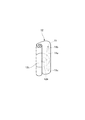
次に、本実施の形態のサイドエアバッグ装置10の動作について、サイドエアバッグ装置10により乗員を保護する乗員保護方法と併せて、図3A、図3B、図3C、図4A、図4B及び図4Cを用いて説明する。図3Aは、本発明の一実施の形態であるサイドエアバッグ装置10の第1の状態を車両の前方側から模式的に示す前方面図であり、図3Bは、本発明の一実施の形態であるサイドエアバッグ装置10の第2の状態を車両の前方側から模式的に示す前方面図であり、図3Cは、本発明の一実施の形態であるサイドエアバッグ装置10の第3の状態を車両の前方側から模式的に示す前方面図である。
Next, regarding the operation of the
また、図4Aは、本発明の一実施の形態であるサイドエアバッグ装置10のエアバッグ12の第1の状態を模式的に示す斜視図であり、図4Bは、本発明の一実施の形態であるサイドエアバッグ装置10のエアバッグ12の第2の状態を模式的に示す斜視図であり、図4Cは、本発明の一実施の形態であるサイドエアバッグ装置10のエアバッグ12の第3の状態を模式的に示す斜視図である。
FIG. 4A is a perspective view schematically showing a first state of the
図3A及び図4Aに例示されるように、通常、サイドエアバッグ装置10のエアバッグ12は、図示しないケース内に収容されている。このとき、本実施の形態のエアバッグ12は、ロール状に折り畳んで収容されている。なお、本実施の形態のエアバッグ12は、上述したように、ロール状に折り畳んで収容されているが、これに限定されず、例えば、蛇腹状に折り畳んで収容しても良い。
As illustrated in FIGS. 3A and 4A, the
図3B及び図4Bに例示されるように、サイドドア20への側突により図示しないセンサが所定以上の衝撃を検知したとき、図示しない制御回路がインフレータ11に動作信号を供給する。
As illustrated in FIG. 3B and FIG. 4B, when a sensor (not shown) detects an impact of a predetermined level or more due to a side collision to the
そして、この制御回路による動作信号に応答して、インフレータ11がエアバッグ12内に供給ガスを供給する。これにより、エアバッグ12の展開が開始される。そして、インフレータ11の第1ガス供給口11bからエアバッグ12の上部チャンバ12a側に供給ガスを供給し、第2ガス供給口11cからエアバッグ12の下部チャンバ12b側に供給ガスを供給している。
In response to the operation signal from the control circuit, the inflator 11 supplies the supply gas into the
このとき、インフレータ11は、エアバッグ12の非膨出部12d付近に配設されている。そして、非膨出部12dは、ドアアームレスト25の車両5の上下方向における同位置に配設されている。
At this time, the
すなわち、本実施の形態のサイドエアバッグ装置10は、エアバッグ12の非膨出部12d付近から上部チャンバ12a及び下部チャンバ12bに供給ガスが供給されるため、ドアアームレスト25を基点としてドアアームレスト25の上部及び下部で上部チャンバ12a及び下部チャンバ12bの展開を可能にしている。
That is, in the
これにより、サイドエアバッグ装置10は、エアバッグ12を展開させる際、このエアバッグ12をドアアームレスト25にぶつからないように展開させることが可能になり、エアバッグ12をより確実に展開させることができる。
Thus, when the
このとき、本実施の形態のサイドエアバッグ装置10は、上述したように、上部チャンバ12a及び下部チャンバ12bをドアアームレスト25にぶつからないように展開させることが可能になるため、車両5の幅方向における幅をサイドドア20と乗員との間の幅とほぼ同じ幅で形成することが可能になる。
At this time, as described above, the
これにより、サイドエアバッグ装置10によれば、サイドドア20と乗員との間の空間を確保、すなわち、サイドドア20から乗員を遠ざけることが可能になり、側突により生じる衝撃に対し、安全性を高めることができる。
Thereby, according to the
図3C及び図4Cに例示されるように、本実施の形態のエアバッグ12は、インフレータ11による供給ガスの供給により上部チャンバ12a及び下部チャンバ12b内での圧力が高まると、圧力弁12eが開放される。
As illustrated in FIGS. 3C and 4C, in the
そして、エアバッグ12は、圧力弁12eが開放されることで、インフレータ11により胸部側チャンバ12c内に供給ガスが供給される。ここで、本実施の形態の胸部側チャンバ12cは、乗員の胸部付近で展開可能となるように構成されている。
The
このように、乗員の胸部付近で胸部側チャンバ12cを展開させることで、サイドドア20と乗員の胸部付近との空間を確保、すなわち、サイドドア20との距離を確保することが可能になり、側突に対する安全性を高めることができる。
Thus, by deploying the
さらに、乗員の胸部付近で胸部側チャンバ12cを展開させることで、上部チャンバ12a、下部チャンバ12b及び胸部側チャンバ12cで乗員の肩部から臀部にかけて面押しすることが可能になり、胸部傷害値を低減させることができる。
Furthermore, by deploying the
また、エアバッグ12は、上部チャンバ12a及び下部チャンバ12bを展開させた後、胸部側チャンバ12cへの展開を開始しているため、胸部側チャンバ12cを上部チャンバ12a及び下部チャンバ12bよりも低圧力で展開させることが可能になる。
Further, since the
このように、サイドエアバッグ装置10は、胸部側チャンバ12cを低圧力で展開させることが可能になるため、胸部側チャンバ12cによる乗員への押圧力を軽減させることができる。
Thus, since the
これにより、サイドエアバッグ装置10によれば、胸部側チャンバ12cによる乗員への胸部障害値を低減させることが可能になり、サイドドア20への側突に対し、安全性を高めることができる。
Thereby, according to the
以上のように、本実施の形態のサイドエアバッグ装置10によれば、サイドドア20への側突時に、一つのインフレータ11で上部チャンバ12a、下部チャンバ12b及び胸部側チャンバ12cが展開可能なエアバッグ12を有し、これら上部チャンバ12a、下部チャンバ12b及び胸部側チャンバ12cにより、サイドドア20と乗員との間の空間を確保、及び、乗員の胸部を保護することで、サイドドア20への側突による衝撃に対する安全性を高めることができる。
As described above, according to the
また、本実施の形態のサイドエアバッグ装置10のエアバッグ12の展開により乗員を保護する乗員保護方法によれば、サイドドア20への側突による衝撃に対する安全性を高めることができる。
Further, according to the occupant protection method that protects the occupant by deploying the
(実施の形態2)
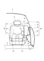
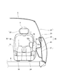
次に、本発明の他の実施の形態について、図5を用いて説明する。図5は、本発明の他の実施の形態であるサイドエアバッグ装置50を適用した車両のサイドドア20及び車両用シート30を示し、サイドエアバッグ装置50のエアバッグ52が展開した状態を車両の前方側から模式的に示す前方面図である。
(Embodiment 2)
Next, another embodiment of the present invention will be described with reference to FIG. FIG. 5 shows a
このサイドエアバッグ装置50は、上述の実施の形態1に対し、エアバッグ52のドアアームレスト側チャンバ52aが一つのチャンバにより構成され、このドアアームレスト側チャンバ52aがドアアームレスト25に向かって展開するよう構成された点が異なり、他の点は同様である。したがって、上述の実施の形態1と同一又は相当する部分には、同様の符号を付してその説明を省略する。
In the
図5に例示されるように、本実施の形態のサイドエアバッグ装置50のエアバッグ52は、ドアアームレスト25の車両5の幅方向における車室面側に向かって展開可能なドアアームレスト側チャンバ52aと、乗員の胸部付近で展開可能な胸部側チャンバ52cと、を備えて構成されている。
As illustrated in FIG. 5, the
このように、本実施の形態のサイドエアバッグ装置50は、エアバッグ52のドアアームレスト側チャンバ52aをドアアームレスト25の車両5の幅方向における車室面側に向かって展開させているため、サイドドア20を構成する各部の中で、乗員に最も近い位置に位置するドアアームレスト25と乗員との空間を確保、すなわち、ドアアームレスト25乗員との距離を確保することが可能になる。
As described above, the
以上のように、本実施の形態のサイドエアバッグ装置50によれば、一つのインフレータ51でドアアームレスト側チャンバ52a及び胸部側チャンバ52cを形成するエアバッグ52を有し、これらドアアームレスト側チャンバ52a及び胸部側チャンバ52cによりドアアームレスト25と乗員との間の空間の確保、及び、乗員の胸部を保護することで、サイドドア20への側突による衝撃から乗員を保護することができる。
As described above, according to the
5 車両
6 フロア
10 サイドエアバッグ装置
11 インフレータ
12 エアバッグ
12a 上部チャンバ
12b 下部チャンバ
12c 胸部側チャンバ
12e 圧力弁
20 サイドドア(車両側壁)
25 ドアアームレスト
30 車両用シート
DESCRIPTION OF
25
Claims (5)
前記エアバッグは、複数の前記チャンバのうち、
車両の上下方向におけるドアアームレストの上部及び下部で展開可能なドアアームレスト側チャンバと、
前記車両の幅方向における前記ドアアームレスト側チャンバよりも車室側で、かつ、前記乗員の胸部付近で展開可能な胸部側チャンバと、を有すること、
を特徴とする乗員保護装置。 An occupant having an airbag capable of forming a plurality of chambers with one inflator, and protecting the occupant from collision with the vehicle side wall by deploying the airbag between the vehicle side wall and the occupant A protective device,
The airbag is a plurality of the chambers.
A door armrest side chamber that can be deployed at the top and bottom of the door armrest in the vertical direction of the vehicle;
A chest side chamber that is deployable in the vehicle compartment side of the door armrest side chamber in the width direction of the vehicle and in the vicinity of the chest of the occupant,
An occupant protection device.
前記エアバッグは、複数の前記チャンバのうち、
車両の幅方向におけるドアアームレストの車室側の面に向かって展開可能なドアアームレスト側チャンバと、
前記車両の幅方向における前記ドアアームレスト側チャンバよりも車室側で、かつ、前記乗員の胸部付近で展開可能な胸部側チャンバと、を有すること、
を特徴とする乗員保護装置。 An occupant having an airbag capable of forming a plurality of chambers with one inflator, and protecting the occupant from collision with the vehicle side wall by deploying the airbag between the vehicle side wall and the occupant A protective device,
The airbag is a plurality of the chambers.
A door armrest side chamber that can be deployed toward a surface of the door armrest in the width direction of the vehicle toward the passenger compartment side;
A chest side chamber that is deployable in the vehicle compartment side of the door armrest side chamber in the width direction of the vehicle and in the vicinity of the chest of the occupant,
An occupant protection device.
を特徴とする請求項1又は2記載の乗員保護装置。 When the pressure of the supply gas supplied to the door armrest side chamber by the inflator reaches a predetermined pressure in the vehicle side wall chamber, the airbag communicates with the door armrest side chamber and the chest side chamber. Having a pressure valve,
The occupant protection device according to claim 1 or 2.
を特徴とする請求項1記載の乗員保護装置。 The door armrest side chamber of the airbag has an upper chamber capable of deploying the upper portion of the door armrest, and a lower chamber capable of deploying the lower portion of the door armrest;
The occupant protection device according to claim 1.
複数の前記チャンバは、
少なくとも一つの前記チャンバがドアアームレストの車両の上下方向における上部及び下部で展開し、
少なくとも一つの前記チャンバが乗員の胸部を保護するように展開すること、
を特徴とする乗員保護方法。 An occupant protection method for protecting an occupant from a collision with the vehicle side wall by deploying an air bag forming a plurality of chambers with a single inflator between the vehicle side wall and the occupant,
The plurality of chambers are
At least one of the chambers expands in the upper and lower parts of the door armrest in the vertical direction of the vehicle,
Deploying at least one of the chambers to protect an occupant's chest;
An occupant protection method.
Priority Applications (4)
| Application Number | Priority Date | Filing Date | Title |
|---|---|---|---|
| JP2011042649A JP2012179956A (en) | 2011-02-28 | 2011-02-28 | Occupant protection apparatus and occupant protection method |
| DE102012201932A DE102012201932A1 (en) | 2011-02-28 | 2012-02-09 | Occupant protection device and occupant protection procedure |
| CN201210043040.5A CN102649416B (en) | 2011-02-28 | 2012-02-22 | Occupant protection apparatus and occupant protection method |
| US13/402,160 US8651515B2 (en) | 2011-02-28 | 2012-02-22 | Occupant protection apparatus and occupant protection method |
Applications Claiming Priority (1)
| Application Number | Priority Date | Filing Date | Title |
|---|---|---|---|
| JP2011042649A JP2012179956A (en) | 2011-02-28 | 2011-02-28 | Occupant protection apparatus and occupant protection method |
Publications (1)
| Publication Number | Publication Date |
|---|---|
| JP2012179956A true JP2012179956A (en) | 2012-09-20 |
Family
ID=46691571
Family Applications (1)
| Application Number | Title | Priority Date | Filing Date |
|---|---|---|---|
| JP2011042649A Pending JP2012179956A (en) | 2011-02-28 | 2011-02-28 | Occupant protection apparatus and occupant protection method |
Country Status (4)
| Country | Link |
|---|---|
| US (1) | US8651515B2 (en) |
| JP (1) | JP2012179956A (en) |
| CN (1) | CN102649416B (en) |
| DE (1) | DE102012201932A1 (en) |
Cited By (6)
| Publication number | Priority date | Publication date | Assignee | Title |
|---|---|---|---|---|
| JP2016068789A (en) * | 2014-09-30 | 2016-05-09 | 三菱自動車工業株式会社 | Side airbag device |
| JP2018172000A (en) * | 2017-03-31 | 2018-11-08 | 株式会社Subaru | Occupant protection device of vehicle |
| KR20190020254A (en) * | 2017-08-18 | 2019-02-28 | 현대자동차주식회사 | Airbag for vehicle |
| JP2019031220A (en) * | 2017-08-09 | 2019-02-28 | トヨタ自動車株式会社 | Side airbag device |
| WO2020162065A1 (en) * | 2019-02-09 | 2020-08-13 | オートリブ ディベロップメント エービー | Side airbag device |
| US11608023B2 (en) | 2021-03-02 | 2023-03-21 | Honda Motor Co., Ltd. | Side airbag device |
Families Citing this family (24)
| Publication number | Priority date | Publication date | Assignee | Title |
|---|---|---|---|---|
| JP6075935B2 (en) | 2011-02-28 | 2017-02-08 | 富士重工業株式会社 | Occupant protection device and occupant protection method |
| JP5514758B2 (en) * | 2011-03-17 | 2014-06-04 | 富士重工業株式会社 | Side airbag device, occupant protection device, and occupant protection method |
| KR101585096B1 (en) * | 2012-03-14 | 2016-01-22 | 아우토리브 디벨롭먼트 아베 | Side airbag module for vehicle |
| JP6070217B2 (en) * | 2013-01-25 | 2017-02-01 | 豊田合成株式会社 | Side airbag device |
| JP6003720B2 (en) * | 2013-02-28 | 2016-10-05 | 豊田合成株式会社 | Head protection airbag device |
| US9139153B2 (en) * | 2013-09-05 | 2015-09-22 | Ford Global Technologies, Llc | Vehicle side impact airbag with laterally extending thoracic chamber |
| DE102013015141B4 (en) * | 2013-09-13 | 2017-08-10 | Trw Automotive Gmbh | Method for protecting a vehicle occupant and gas bag |
| JP6217350B2 (en) * | 2013-11-29 | 2017-10-25 | 三菱自動車工業株式会社 | Side airbag device |
| US8967665B1 (en) * | 2014-01-23 | 2015-03-03 | GM Global Technology Operations LLC | Inflatable cushion for a side-impact airbag |
| US9399441B2 (en) * | 2014-03-25 | 2016-07-26 | Ford Global Technologies, Llc | Shape adaptive passenger airbag |
| DE102014006862A1 (en) * | 2014-05-13 | 2015-11-19 | Trw Automotive Gmbh | Vehicle occupant protection device and vehicle seat |
| JP6447432B2 (en) * | 2015-09-11 | 2019-01-09 | トヨタ自動車株式会社 | Far-side airbag device and vehicle seat |
| JP6265189B2 (en) * | 2015-09-11 | 2018-01-24 | トヨタ自動車株式会社 | Side airbag device for rear seats |
| JP6450855B2 (en) * | 2015-10-23 | 2019-01-09 | オートリブ ディベロップメント エービー | Side airbag device |
| EP3459795B1 (en) * | 2016-05-20 | 2020-11-25 | Autoliv Development AB | Side airbag device |
| JP6543651B2 (en) * | 2017-03-31 | 2019-07-10 | 株式会社Subaru | Armrest |
| US10407017B2 (en) | 2017-06-09 | 2019-09-10 | Honda Motor Co., Ltd. | Vehicle side airbag system, and methods of use and manufacture thereof |
| EP3663140B1 (en) * | 2017-08-01 | 2021-11-03 | Autoliv Development AB | Occupant protection device |
| DE102017217499A1 (en) * | 2017-09-29 | 2019-04-04 | Joyson Safety Systems Germany Gmbh | Airbag unit for a motor vehicle |
| US10703321B2 (en) * | 2017-11-20 | 2020-07-07 | Ford Global Technologies, Llc | Airbag assembly |
| JP2019111916A (en) * | 2017-12-22 | 2019-07-11 | トヨタ自動車株式会社 | Vehicle side airbag device |
| US11007971B2 (en) * | 2019-02-15 | 2021-05-18 | Ford Global Technologies, Llc | Side airbag including spacer chamber |
| JP7180456B2 (en) * | 2019-03-06 | 2022-11-30 | トヨタ自動車株式会社 | Seat structure with far side airbag device |
| US11059442B2 (en) * | 2019-03-26 | 2021-07-13 | Trw Vehicle Safety Systems Inc. | Adaptive side airbag for protecting occupants in a vehicle |
Citations (2)
| Publication number | Priority date | Publication date | Assignee | Title |
|---|---|---|---|---|
| JP2008201172A (en) * | 2007-02-16 | 2008-09-04 | Toyota Motor Corp | Side airbag device |
| JP2011001051A (en) * | 2009-05-20 | 2011-01-06 | Honda Motor Co Ltd | Side airbag device |
Family Cites Families (31)
| Publication number | Priority date | Publication date | Assignee | Title |
|---|---|---|---|---|
| JP3456754B2 (en) * | 1994-06-14 | 2003-10-14 | 本田技研工業株式会社 | How to deploy vehicle airbags |
| US5913536A (en) | 1996-02-07 | 1999-06-22 | Trw Vehicle Safety System Inc. | Air bag module |
| EP0849129B1 (en) * | 1996-12-21 | 2004-06-16 | Volkswagen Aktiengesellschaft | Side air bag system for a motor vehicle |
| US6142521A (en) * | 1998-07-15 | 2000-11-07 | Shephard; Mark E. | Vehicle crash protective system |
| WO2000071389A1 (en) | 1999-05-21 | 2000-11-30 | Volkswagen Aktiengesellschaft | Airbag device for a motor vehicle |
| US6851706B2 (en) * | 2002-03-21 | 2005-02-08 | Autoliv Asp, Inc. | Side-impact, variable thickness vehicular airbag |
| JP3950356B2 (en) * | 2002-03-29 | 2007-08-01 | 本田技研工業株式会社 | Side airbag device |
| JP2004210257A (en) * | 2002-12-18 | 2004-07-29 | Takata Corp | Head part protection air bag and head part protection air bag device |
| GB2397048A (en) * | 2003-01-10 | 2004-07-14 | Autoliv Dev | Vehicle seat comprising airbag |
| JP4075680B2 (en) * | 2003-05-08 | 2008-04-16 | 豊田合成株式会社 | Side airbag device |
| JP4622386B2 (en) | 2004-08-24 | 2011-02-02 | タカタ株式会社 | Air bag and air bag device |
| GB2408023A (en) * | 2003-11-11 | 2005-05-18 | Autoliv Dev | Side air bag with internal tether |
| DE102004004544A1 (en) * | 2004-01-23 | 2005-08-11 | Takata-Petri (Ulm) Gmbh | Passenger protection system for vehicles comprises a side airbag having an opening from which gas can penetrate |
| DE102004009013B4 (en) | 2004-02-25 | 2006-03-16 | Trw Automotive Gmbh | Side impact restraint device |
| US7549672B2 (en) * | 2004-05-27 | 2009-06-23 | Toyoda Gosei Co., Ltd. | Side airbag device |
| US7316415B2 (en) * | 2004-08-30 | 2008-01-08 | Autoliv Asp, Inc. | Dual chamber airbag |
| US20060131845A1 (en) * | 2004-12-22 | 2006-06-22 | Ford Global Technologies, Llc | A multi-chambered air bag for a motor vehicle |
| JP4516523B2 (en) * | 2005-12-28 | 2010-08-04 | 本田技研工業株式会社 | Vehicle airbag device |
| JP5007047B2 (en) * | 2006-01-13 | 2012-08-22 | 本田技研工業株式会社 | Airbag device |
| KR101056945B1 (en) | 2006-07-17 | 2011-08-17 | 델피 테크놀로지스 인코포레이티드 | Inflatable cushion for vehicle side, vehicle airbag module having same, and method for protecting vehicle side |
| JP2008074248A (en) | 2006-09-21 | 2008-04-03 | Takata Corp | Air bag device |
| JP2009006860A (en) * | 2007-06-28 | 2009-01-15 | Toyoda Gosei Co Ltd | Occupant crash protection device for vehicle |
| JP5485990B2 (en) * | 2008-07-15 | 2014-05-07 | タカタ・ペトリ アーゲー | Vehicle seat device for automobile and vehicle occupant protection method |
| JP5012726B2 (en) * | 2008-08-07 | 2012-08-29 | 豊田合成株式会社 | Head protection airbag device |
| JP5437272B2 (en) * | 2008-12-29 | 2014-03-12 | 本田技研工業株式会社 | Side airbag device |
| US8408591B2 (en) * | 2009-04-17 | 2013-04-02 | Autoliv Asp, Inc. | Inflatable curtain airbags with expanded-volume lower portions for ejection mitigation |
| DE102009031615A1 (en) * | 2009-07-03 | 2011-01-05 | GM Global Technology Operations, Inc., Detroit | Air bag arrangement for use in e.g. motor vehicle, has airbag formed such that head chamber is filled with gas by region of thorax chamber, where direction of main gas flow corresponds to and/or parallel to thorax chamber |
| JP5679721B2 (en) | 2009-07-24 | 2015-03-04 | ロート製薬株式会社 | Pharmaceutical composition containing Kampo extract |
| US8186708B2 (en) * | 2010-03-08 | 2012-05-29 | Ford Global Technologies, Llc | Asymmetric side airbag for improved head and neck protection |
| US8322747B2 (en) * | 2010-07-14 | 2012-12-04 | Autoliv Asp, Inc. | Inflatable airbag assemblies with arm-manipulating side airbags |
| JP6075935B2 (en) | 2011-02-28 | 2017-02-08 | 富士重工業株式会社 | Occupant protection device and occupant protection method |
-
2011
- 2011-02-28 JP JP2011042649A patent/JP2012179956A/en active Pending
-
2012
- 2012-02-09 DE DE102012201932A patent/DE102012201932A1/en not_active Withdrawn
- 2012-02-22 US US13/402,160 patent/US8651515B2/en active Active
- 2012-02-22 CN CN201210043040.5A patent/CN102649416B/en not_active Expired - Fee Related
Patent Citations (2)
| Publication number | Priority date | Publication date | Assignee | Title |
|---|---|---|---|---|
| JP2008201172A (en) * | 2007-02-16 | 2008-09-04 | Toyota Motor Corp | Side airbag device |
| JP2011001051A (en) * | 2009-05-20 | 2011-01-06 | Honda Motor Co Ltd | Side airbag device |
Cited By (10)
| Publication number | Priority date | Publication date | Assignee | Title |
|---|---|---|---|---|
| JP2016068789A (en) * | 2014-09-30 | 2016-05-09 | 三菱自動車工業株式会社 | Side airbag device |
| JP2018172000A (en) * | 2017-03-31 | 2018-11-08 | 株式会社Subaru | Occupant protection device of vehicle |
| JP2019031220A (en) * | 2017-08-09 | 2019-02-28 | トヨタ自動車株式会社 | Side airbag device |
| KR20190020254A (en) * | 2017-08-18 | 2019-02-28 | 현대자동차주식회사 | Airbag for vehicle |
| KR102530685B1 (en) * | 2017-08-18 | 2023-05-11 | 현대자동차주식회사 | Airbag for vehicle |
| WO2020162065A1 (en) * | 2019-02-09 | 2020-08-13 | オートリブ ディベロップメント エービー | Side airbag device |
| JPWO2020162065A1 (en) * | 2019-02-09 | 2021-10-07 | オートリブ ディベロップメント エービー | Side airbag device |
| JP7100163B2 (en) | 2019-02-09 | 2022-07-12 | オートリブ ディベロップメント エービー | Side airbag device |
| US11752966B2 (en) | 2019-02-09 | 2023-09-12 | Autoliv Development Ab | Side airbag device |
| US11608023B2 (en) | 2021-03-02 | 2023-03-21 | Honda Motor Co., Ltd. | Side airbag device |
Also Published As
| Publication number | Publication date |
|---|---|
| US20120217731A1 (en) | 2012-08-30 |
| DE102012201932A1 (en) | 2012-09-13 |
| CN102649416B (en) | 2015-04-22 |
| US8651515B2 (en) | 2014-02-18 |
| CN102649416A (en) | 2012-08-29 |
Similar Documents
| Publication | Publication Date | Title |
|---|---|---|
| JP2012179956A (en) | Occupant protection apparatus and occupant protection method | |
| JP6075935B2 (en) | Occupant protection device and occupant protection method | |
| JP5401495B2 (en) | Side airbag device, occupant protection device, and occupant protection method | |
| KR102547636B1 (en) | Air bag device for car | |
| JP6278006B2 (en) | Crew protection device | |
| JP5514758B2 (en) | Side airbag device, occupant protection device, and occupant protection method | |
| JP5918621B2 (en) | Side airbag device | |
| JP6411971B2 (en) | Crew protection device | |
| JP6263627B2 (en) | Airbag device | |
| JP5783193B2 (en) | Curtain airbag device and occupant protection device | |
| US8770618B2 (en) | Curtain airbag device | |
| JP7449930B2 (en) | Side airbag device and method for manufacturing the side airbag device | |
| WO2012117561A1 (en) | Side airbag device for automobile | |
| JP5495738B2 (en) | Airbag | |
| JP7073534B2 (en) | A method for manufacturing a side airbag device, a vehicle seat equipped with the side airbag device, and a side airbag device. | |
| US10246039B2 (en) | Airbag device | |
| WO2013161626A1 (en) | Curtain airbag device | |
| KR20130083264A (en) | Passenger air bag module | |
| JP6183184B2 (en) | Side airbag device | |
| KR20220139183A (en) | Side airbag apparatus for vehicle | |
| JP2018012474A (en) | Vehicular occupant restraint device | |
| JP5369732B2 (en) | Vehicle interior structure | |
| JP2019112020A (en) | Fitting structure of seat cushion airbag device | |
| JP2018149992A (en) | Center airbag device | |
| JP2015039962A (en) | Side airbag device |
Legal Events
| Date | Code | Title | Description |
|---|---|---|---|
| A621 | Written request for application examination |
Free format text: JAPANESE INTERMEDIATE CODE: A621 Effective date: 20131122 |
|
| A977 | Report on retrieval |
Free format text: JAPANESE INTERMEDIATE CODE: A971007 Effective date: 20140529 |
|
| A131 | Notification of reasons for refusal |
Free format text: JAPANESE INTERMEDIATE CODE: A131 Effective date: 20140603 |
|
| A521 | Request for written amendment filed |
Free format text: JAPANESE INTERMEDIATE CODE: A523 Effective date: 20140801 |
|
| A02 | Decision of refusal |
Free format text: JAPANESE INTERMEDIATE CODE: A02 Effective date: 20140826 |
|
| A521 | Request for written amendment filed |
Free format text: JAPANESE INTERMEDIATE CODE: A523 Effective date: 20141117 |
|
| A911 | Transfer to examiner for re-examination before appeal (zenchi) |
Free format text: JAPANESE INTERMEDIATE CODE: A911 Effective date: 20141126 |
|
| A912 | Re-examination (zenchi) completed and case transferred to appeal board |
Free format text: JAPANESE INTERMEDIATE CODE: A912 Effective date: 20141226 |