JP2012178824A - Image processing apparatus and method of creating profile - Google Patents
Image processing apparatus and method of creating profile Download PDFInfo
- Publication number
- JP2012178824A JP2012178824A JP2012019854A JP2012019854A JP2012178824A JP 2012178824 A JP2012178824 A JP 2012178824A JP 2012019854 A JP2012019854 A JP 2012019854A JP 2012019854 A JP2012019854 A JP 2012019854A JP 2012178824 A JP2012178824 A JP 2012178824A
- Authority
- JP
- Japan
- Prior art keywords
- color
- point
- gamut
- profile
- color gamut
- Prior art date
- Legal status (The legal status is an assumption and is not a legal conclusion. Google has not performed a legal analysis and makes no representation as to the accuracy of the status listed.)
- Granted
Links
Images


Classifications
-
- H—ELECTRICITY
- H04—ELECTRIC COMMUNICATION TECHNIQUE
- H04N—PICTORIAL COMMUNICATION, e.g. TELEVISION
- H04N1/00—Scanning, transmission or reproduction of documents or the like, e.g. facsimile transmission; Details thereof
- H04N1/46—Colour picture communication systems
- H04N1/56—Processing of colour picture signals
- H04N1/60—Colour correction or control
- H04N1/603—Colour correction or control controlled by characteristics of the picture signal generator or the picture reproducer
-
- H—ELECTRICITY
- H04—ELECTRIC COMMUNICATION TECHNIQUE
- H04N—PICTORIAL COMMUNICATION, e.g. TELEVISION
- H04N1/00—Scanning, transmission or reproduction of documents or the like, e.g. facsimile transmission; Details thereof
- H04N1/46—Colour picture communication systems
- H04N1/56—Processing of colour picture signals
- H04N1/60—Colour correction or control
- H04N1/6058—Reduction of colour to a range of reproducible colours, e.g. to ink- reproducible colour gamut
Landscapes
- Engineering & Computer Science (AREA)
- Multimedia (AREA)
- Signal Processing (AREA)
- Image Processing (AREA)
- Facsimile Image Signal Circuits (AREA)
- Color Image Communication Systems (AREA)
Abstract
Description
本発明は、画像処理装置およびプロファイル作成方法に関し、詳しくは、入力デバイスの色域を出力デバイスの色域へ変換するガマットマッピングに関するものである。 The present invention relates to an image processing apparatus and a profile creation method, and more particularly to gamut mapping for converting a color gamut of an input device to a color gamut of an output device.
入出力デバイス間でデバイスに依存しない色再現技術を実現するための、いわゆるカラーマネージメントシステム(CMS)などでは、入出力デバイス間の色再現範囲の違いを吸収するガマットマッピングの技術が用いられている。従来、ガマットマッピングの一手法として、例えば、明度軸上の固定された1点(例えばL*=50、以下このような‘点’で表現される色を焦点色と呼ぶ)に向かって引いた補助線上の点にマッピングするアルゴリズムが知られている。 In a so-called color management system (CMS) or the like for realizing a device-independent color reproduction technique between input / output devices, a gamut mapping technique that absorbs a difference in color reproduction range between input / output devices is used. . Conventionally, as a method of gamut mapping, for example, it is drawn toward a fixed point on the lightness axis (for example, L * = 50; hereinafter, a color represented by such a “point” is referred to as a focal color). An algorithm for mapping to a point on an auxiliary line is known.
特許文献1には、焦点色を用いたガマットマッピングの一例が開示されている。特許文献1には、測色的手法を用いて入力画像を出力色域にマッピングする際に、彩度を重視してマッピングする方法や、明度を重視してマッピングする方法などが記載されている。これらは、マッピングの特性に応じて焦点色の移動範囲を制御し、さらに入力値の明度に応じて焦点色を異ならせるものである。
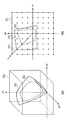
図1(a)および(b)は、標準色空間を、そのある色相の、明度(L*)軸と彩度(C*)軸で規定される面として示す図である。これらの図は、標準色空間で定義されたある明度の格子点のデータPinに関して、それぞれ彩度重視および明度重視の条件で設定されたL軸上の固定された焦点色の範囲(上限値L_max、下限値L_min)と、それぞれの範囲内の焦点に向うよう、特許文献1の方法でマッピングした結果とを例示している。焦点色は、格子点の明度に応じて適応的に焦点色を設定する下記の式(1)により算出される。この式で、L(S)は焦点色の明度値、L_inは格子点のデータの明度値、Ltは入力空間の最も高い明度値、Lbは入力空間の最も低い明度値を示している。
FIGS. 1A and 1B are diagrams showing a standard color space as a plane defined by a lightness (L * ) axis and a saturation (C * ) axis of a certain hue. These figures show fixed focus color ranges (upper limit value L_max) on the L-axis set under the conditions of emphasis on saturation and lightness, respectively, with respect to data Pin of a certain lightness grid point defined in the standard color space. , Lower limit value L_min) and the result of mapping by the method of
L(S)=(L_max−L_min)・L_in/(Lt−Lb)+L1_min… (1) L (S) = (L_max−L_min) · L_in / (Lt−Lb) + L1_min (1)
従来の方法では、無彩色軸(L軸)上の焦点色(Ls、0、0)は、入力点の明度L_inに応じてL_minからL_maxの間を移動する。式(1)によれば、L_minとL_maxの差が小さければ、焦点色は無彩色軸上の狭い範囲を動き、図1(a)に示すように彩度を重視したマッピングとなる。一方、L_minとL_maxの差が大きければ、焦点色は無彩色軸上の広い範囲を動き、図1(b)に示すように明度を重視したマッピングとなる。これにより、彩度を重視したマッピングや、明度を重視したマッピングなど、マッピングの特性を選択でき、マッピングの特性にユーザの要求を反映させることなどが可能となる。 In the conventional method, the focus color (Ls, 0, 0) on the achromatic color axis (L axis) moves between L_min and L_max according to the lightness L_in of the input point. According to Expression (1), if the difference between L_min and L_max is small, the focus color moves in a narrow range on the achromatic color axis, and mapping is performed with emphasis on saturation as shown in FIG. On the other hand, if the difference between L_min and L_max is large, the focus color moves in a wide range on the achromatic color axis, and mapping is performed with emphasis on brightness as shown in FIG. Thereby, mapping characteristics such as mapping with emphasis on saturation and mapping with emphasis on lightness can be selected, and the user's request can be reflected on the mapping characteristics.
しかしながら、特許文献1に記載されるような焦点色を用いたマッピングでは、出力デバイスの色域の形状によっては「明度ジャンプ」と呼ばれる明度の大きな変化を生じることがある。その結果、入力デバイスで再現される色と出力デバイスで再現される色の見た目の印象が異なるという問題がある。
However, in the mapping using the focus color as described in
図2は、この問題を説明するための図であり、標準色空間301において、入力デバイスの色域300の色が、焦点色Qを用いて出力デバイスであるプリンタの色域302にマッピングされる例を示している。図2に示すように、焦点色Qを用いたマッピングでは、標準色空間301で定義される、入力デバイスの色域300の同じ明度の色P1in、P2in、P3inは、出力デバイスの色域の色P1out、P2out、P3outにそれぞれマッピングされる。より詳しくは、出力デバイスの色域302内にある入力デバイスの色域300の色P1inはそのままの色にマッピングされる。これに対して、出力デバイスの色域302の外にある入力デバイスの色域300の色P2in、P3inは、マッピングによってそれぞれ焦点色Qに向かって引いた直線上で色域302の表面上の点に圧縮される。そして、このような圧縮の結果として得られる色P2outと色P3outとの間に大きな明度差が発生する。すなわち、色P2outと色P3outは、出力デバイスの色域302における最大彩度の色Cより高明度側と低明度側にそれぞれマッピングされ、その結果、入力デバイスの色域300では同じ明度の色であっても、出力デバイスの色域302では大きく明度が異なる色となる。そして、このような大きな明度差が発生すると、入力デバイスで再現される色と出力デバイスで再現される色の見た目の印象が異なることになる。
FIG. 2 is a diagram for explaining this problem. In the
特許文献1では、このような焦点色を用いるマッピングを行うことから、出力デバイスの色域の形状によっては、上述した明度ジャンプを生じ得ることになる。
In
本発明は、上記課題を解決するためになされたものであり、ガマットマッピングを行う際に、出力デバイスの色域形状によらず明度ジャンプを防ぎ、良好な色再現を行うことができる画像処理装置およびプロファイル作成方法を提供することを目的とする。 The present invention has been made in order to solve the above-described problem. When performing gamut mapping, an image processing apparatus capable of preventing lightness jumps and performing good color reproduction regardless of the color gamut shape of an output device. And providing a profile creation method.
そのために本発明では、色空間において、第1の色域で定義される格子点の色を、該色と無彩色軸上の焦点色とを結ぶ直線上の色にマッピングすることによって第2の色域の色に変換するためのプロファイルを作成する画像処理装置であって、前記格子点の色が、格子点の色が属する色相の面において前記第2の色域の最大彩度点の明度より高く、かつ前記最大彩度点の彩度より高い第1の分割領域と、それ以外の第2の分割領域のいずれに属するかを判断する判断手段と、前記判断された領域に応じて、前記第1の色域で定義される格子点の色をマッピングして前記第2の色域の色に変換する変換手段と、複数の格子点の色それぞれの前記変換の結果に基づいてプロファイルを作成するプロファイル作成手段と、を具え、前記変換手段は、前記格子点の色が前記第1の分割領域に属する場合は、格子点の色と前記最大彩度点を結ぶ直線と無彩色軸との交点の明度以上の色を焦点色に設定し、前記格子点の色をマッピングすることを特徴とする。 Therefore, in the present invention, in the color space, the color of the lattice point defined in the first color gamut is mapped to the color on the straight line connecting the color and the focal color on the achromatic color axis. An image processing apparatus for creating a profile for conversion into a color gamut color, wherein the color of the grid point is the brightness of the maximum saturation point of the second color gamut in the hue plane to which the color of the grid point belongs According to a determination means for determining which one of the first divided region higher than the saturation of the maximum saturation point and the other second divided region belongs to, and the determined region, Mapping means for mapping the color of the grid point defined in the first color gamut to convert it to the color of the second color gamut, and a profile based on the result of the conversion of each color of the plurality of grid points Profile creating means for creating, the converting means comprising: If the color of the grid point belongs to the first divided area, the color more than the brightness of the intersection of the achromatic color axis and the straight line connecting the color of the grid point and the maximum saturation point is set as the focus color, It is characterized by mapping the color of grid points.
以上の構成によれば、マッピングされる格子点の色が、格子点の色が属する色相の面において、例えば出力デバイスの色域である第2の色域の最大彩度点の明度より高く、かつ前記最大彩度点の彩度より高い第1の分割領域に存在するか否かが判断される。そして、格子点の色が第1の分割領域に存在する場合は、格子点の色と前記最大彩度点を結ぶ直線と無彩色軸との交点の明度以上の位置に焦点色が設定され、前記格子点の色がマッピングされる。これにより、格子点に対応した出力色が第2の色域の最大彩度の点に対して高明度側と低明度側の色に分かれること、つまり、大きな明度の違いが生じることを防ぐことができる。 According to the above configuration, the color of the mapped grid point is higher than the brightness of the maximum saturation point of the second color gamut that is the color gamut of the output device, for example, in the hue plane to which the color of the grid point belongs, And it is judged whether it exists in the 1st division area higher than the saturation of the maximum saturation point. When the color of the grid point is present in the first divided region, the focus color is set at a position equal to or higher than the brightness of the intersection of the straight line connecting the color of the grid point and the maximum saturation point and the achromatic color axis, The color of the grid point is mapped. This prevents the output color corresponding to the grid point from being divided into a high brightness side color and a low brightness side color with respect to the maximum saturation point of the second color gamut, that is, a large difference in brightness. Can do.
以下、図面を参照して本発明の実施形態を詳細に説明する。
(第1実施形態)
本発明の第1の実施形態は、標準色空間において、入力デバイスの色域を出力デバイスの色域にマッピングするためのプロファイルを生成する装置および方法に関するものである。
Hereinafter, embodiments of the present invention will be described in detail with reference to the drawings.
(First embodiment)
The first embodiment of the present invention relates to an apparatus and method for generating a profile for mapping a color gamut of an input device to a color gamut of an output device in a standard color space.
[画像処理装置の構成]
図3は、本実施形態に係る画像処理装置の構成を示すブロック図である。本実施形態の画像処理装置は、ホストコンピュータにおいてプログラムが実行されることによって実現されるものである。図3において、CPU500は、ROM501に記憶されている情報データや各種プログラムに従って、RAM502、操作部503、画像処理部504、モニター505、画像入力装置506、画像出力装置507の各種制御を行う。ROM501に記憶されているプログラムとしては、制御プログラムやOS(オペレーティングシステム)、アプリケーションプログラム、色変換処理モジュール、デバイスドライバ等がある。情報記憶部508は、ハードディスクや不揮発性メモリからなるものであり、後述する情報およびデータを格納、読み出しするための記憶部である。測色部509は、出力色再現領域およびプロファイル生成に必要な情報を取得するために、画像出力装置507で印刷されたパッチチャートを測色する。なお、本実施形態では、CPU500の制御によって測色し、情報記憶部508に測色情報を格納する構成を示しているが、画像出力装置507に設けられた測色器で測定し、その測色情報を画像出力装置507の所定の記録部に格納するようにしてもよい。
[Configuration of image processing apparatus]
FIG. 3 is a block diagram illustrating a configuration of the image processing apparatus according to the present embodiment. The image processing apparatus according to the present embodiment is realized by executing a program in a host computer. In FIG. 3, the
画像入力装置506は、例えばデジタルカメラやイメージスキャナ等であり、後述するプロファイルを用いて処理を行う画像データの入力部を構成する。また、画像出力装置507は、モニターやインクジェットプリンタ、熱転写プリンタ、ドットプリンタ等によって実現できる。本実施形態では、シアン、淡シアン、マゼンタ、淡マゼンタ、イエロー、ブラックの6色のインクを用いたインクジェットプリンタ装置の形態である。
The
RAM502は、CPU500が動作するに際して、各種制御プログラムや操作部503から入力されるデータの作業領域および一時退避領域として利用することができる。操作部503は、ユーザの操作に基づいて画像出力装置507の設定やデータの入力を行う。画像処理部504は、後述するプロファイル作成処理やプロファイルを用いた色変換処理等の所定の画像処理を行う。モニター505は、画像処理部504の処理結果や操作部503で入力されたデータ等を表示することができる。
The
なお、以上説明した形態に限られず、プリンタなどの印刷装置でこの画像処理装置の一部または全部を構成してもよい。例えば、デジタルカメラで撮影した画像を直接プリンタに入力して印刷出力をする形態では、そのプリンタに画像処理装置を構成し上述した各種処理を実行するようにすることもできる。また、後述のプロファイルの作成処理は、上述した画像処理装置としてのホストコンピュータにおいて実施することができ、また、その作成されたプロファイルは画像処理装置としてのホストコンピュータまたはプリンタなどの所定のメモリに格納して用いることができる。 Note that the present invention is not limited to the embodiment described above, and a part or all of the image processing apparatus may be configured by a printing apparatus such as a printer. For example, in a form in which an image captured by a digital camera is directly input to a printer and printed out, an image processing apparatus can be configured in the printer and the above-described various processes can be executed. The profile creation process described later can be performed by the host computer as the image processing apparatus described above, and the created profile is stored in a predetermined memory such as a host computer or a printer as the image processing apparatus. Can be used.
本実施形態で用いる色空間は、入力色空間がAdobeRGB空間、標準色空間がCIE−L*a*b*色空間であり、生成するプロファイルは、CIE−L*a*b*色空間からプリンタのデバイスRGB値に変換するためのプロファイルである。また、以下で説明する実施形態では、色域マッピングの方法として測色的(Colorimetric)処理の例を示す。測色的処理では、入力デバイスと出力デバイスで共通の色域はそのまま表現し、画像出力装置507では色再現ができない非共通の領域については、入力デバイスの色を出力色域表面にマッピングする。
In the color space used in the present embodiment, the input color space is the AdobeRGB space, the standard color space is the CIE-L * a * b * color space, and the generated profile is from the CIE-L * a * b * color space to the printer. It is a profile for converting into device RGB values. In the embodiment described below, an example of colorimetric processing is shown as a color gamut mapping method. In the colorimetric processing, the color gamut common to the input device and the output device is expressed as it is, and the color of the input device is mapped to the surface of the output gamut for the non-common region that cannot be reproduced by the
図4は、後述される本実施形態の処理によって生成されたプロファイルを用いる画像処理の構成を示すブロック図である。印刷される画像データは、RGBの色成分信号を有する画像データであり、画像データI/F部601はこのRGB画像データを受け付ける。次に、入力空間変換処理部602は、このRGB画像データをその属性に応じて、標準色空間(L*a*b*、J*C*H*色空間、sRGB、AdobeRGB等)の画像データ(入力画像データ)に変換する。本実施形態では、標準色空間としてL*a*b*色空間を用いる。また、入力空間変換処理部602は、3次元ルックアップテーブル(LUT)を用いて変換処理を行う。この3次元LUTの変換パラメータは入力プロファイル604の情報に基づくものであり、入力プロファイル604の情報が入力係数変換部603によって入力空間変換処理部用のパラメータに変換されることによって設定される。
FIG. 4 is a block diagram showing a configuration of image processing using a profile generated by processing of the present embodiment described later. The image data to be printed is image data having RGB color component signals, and the image data I /
出力空間変換処理部605は、入力空間変換処理部602の処理によって得られた、標準色空間における入力画像データを、デバイス依存のRGB画像データ(出力画像データ)に変換する。この処理も3次元−LUTの変換パラメータを用いて行われる。すなわち、この3次元LUTの処理パラメータは、出力プロファイル607の情報に基づくものであり、出力プロファイル607の情報が出力係数変換部606によって出力空間変換処理部用のパラメータに変換されることによって設定される。出力プロファイル607は、図6およびそれ以降の図を参照して後述される処理によって作成されたプロファイルである。
The output space
出力空間変換処理部605で得られたデバイス依存のRGB画像データは、色材色展開処理部608によって、画像出力装置507で用いる色材に応じた色成分信号の画像データに展開(変換)される。この処理も3次元−LUTを用いて行われる。本実施形態では、シアン、淡シアン、マゼンタ、淡マゼンタ、イエロー、ブラックの色成分信号からなる画像データに変換される。色材色展開処理部608で用いるパラメータは、印刷情報DB613に格納されたLUTパラメータが色材係数変換部609によって変換されることによって設定される。印刷情報DB613には、色材色展開処理部608、ハーフトーニング処理部610、印刷制御部611で処理を行うための各種パラメータが格納されている。各種パラメータの説明は省略するが、印刷に用いる印刷媒体の種類、印刷モード、印刷目的などに応じた各種パラメータ情報が管理され、必要に応じて選択、設定されるものである。色材のデータに展開されたデータは、次に、ハーフトーニング処理部610で、2値データに変換される。この処理は、誤差拡散処理法、ディザ法など公知の量子化手法を用いることができる。印刷制御部611は、得られた2値データに基づき、印刷パス数に応じた印刷制御を行うが、ここでの詳細な説明は省略する。なお、以上説明した例は、RGB信号成分からなる画像データに基づいた画像処理に係るものであるが、この例に限られないことはもちろんである。例えば、CMYK信号成分からなる画像データに基づき画像出力する場合も同様に本発明を適用することができる。
The device-dependent RGB image data obtained by the output space
[プロファイルの作成]
以下では、図4に示した出力プロファイル607の作成に本発明を適用した形態について説明する。出力プロファイルの作成処理は、図3に示したCPU500が、ROM501に格納されている、プロファイルパラメータを作成するためのソフトウェアに従った処理を実行することによって行われる。
[Create profile]
Hereinafter, an embodiment in which the present invention is applied to the creation of the
図5(a)および(b)は、標準色空間における入力デバイスの色域(第1の色域)を出力デバイスの色域(第2の色域)へのマッピングと、このマッピングを記述した出力プロファイルを構成するルックアップテーブルとの関係を説明する図である。図5(a)に示すように、例えば、入力デバイスの色空間としてのAdobeRGB色空間は、CIE−L*a*b*色空間の標準色空間301において色域300として表される。また、出力デバイスであるプリンタ(画像出力装置507)の色空間は標準色空間301において色域302として表される。ルックアップテーブルを構成する各格子点は、図5(b)に示すように、入力デバイスの色域300の色を含んで標準色空間301における色(黒い点で示される)として定義される。そして、それぞれの格子点には、その格子点の色がマッピングされる先の色である色が格子点データとして規定される。具体的には、この格子点データは、出力デバイスの色域302におけるマッピングされる先の色として、標準色空間のL*a*b*値に対応したデバイスRGB値のデータで表される。本実施形態のプロファイルないしその作成方法は、以上説明した、標準色空間301において、入力デバイスの色域300を出力デバイスの色域302にマッピングする例における出力プロファイルに関するものである。
FIGS. 5A and 5B describe the mapping of the input device color gamut (first color gamut) to the output device color gamut (second color gamut) in the standard color space, and this mapping. It is a figure explaining the relationship with the lookup table which comprises an output profile. As shown in FIG. 5A, for example, the AdobeRGB color space as the color space of the input device is represented as a
図6は、カラープロファイルを作成する処理を示すフローチャートである。また、図7は、本実施形態で説明するガマットマッピングの方法を説明するための模式図である。 FIG. 6 is a flowchart showing a process for creating a color profile. FIG. 7 is a schematic diagram for explaining the gamut mapping method described in the present embodiment.
図6において、先ず、ステップS700で作成する出力プロファイルの格子点データの情報を設定する。以下の説明では、出力プロファイルが、図5(b)に示すように、各軸9点の729個の格子点を有するよう設定する例について説明する。具体的には、操作部503およびモニター505(図3)を介してこの各軸9点の格子点を設定する。この指示により、CIE−L*a*b*色空間で規定される格子点数は、729(9×9×9)個の格子点であり、以下の説明では、これら格子点のL*a*b*値をL_in(i)、a_in(j)、b_in(k)(ただし、i、j、kは、0〜8)とする。
In FIG. 6, first, information of grid point data of the output profile created in step S700 is set. In the following description, an example will be described in which the output profile is set to have 729 lattice points with 9 points on each axis, as shown in FIG. 5B. Specifically, nine grid points on each axis are set via the
次に、ステップS701で、予め記憶してあるパッチチャート画像データを、出力デバイスである画像出力装置507によって印刷し、この印刷されたパッチを測色することによって画像出力装置の出力色域の情報を取得する。本実施形態では、各軸9点の格子点であるので、後述のデータの補間処理も考慮し、その中間色の測色値を得るために、RGB色空間上の各軸を16分割した各軸17点の、17×17×17=4913色のパッチを印刷する。そして、測色部509によって測色された測色データ(L*a*b*値)を情報記憶部508に記憶する。
Next, in step S701, the patch chart image data stored in advance is printed by the
具体的なパッチチャートの印刷動作では、図4に示した画像データI/F部601に上記パッチチャート画像データが入力される。ここでは、画像出力装置507の出力色再現領域の情報を取得するために、入力空間変換処理部602、出力空間変換処理部605では処理を行わず、RGB信号がそのまま色材色展開処理部608に入力される。色材色展開処理部608は、印刷情報DB613、色材係数変換部609によって設定された、対象とする用紙用のパラメータを用いて、シアン、淡シアン、マゼンタ、淡マゼンタ、イエロー、ブラックの6色のインクに対応した色成分信号の画像データに展開する。そして、印刷情報DB613および印刷係数変換部612の処理に基づいて、ハーフトーニング処理部610で2値データを求め、印刷制御部611を介して印刷される。
In a specific patch chart printing operation, the patch chart image data is input to the image data I /
情報記憶部508では、上記のように得られた測色値を次の2つの出力色域情報に変換して記憶する。第1の出力色域情報は、測色値であるL*a*b*値に最も近い色(色差が最少の色)として再現されるRGB値を対応させた情報である。すなわち、測色値は、RGB値に基づいて印刷されたパッチを測色して得られるLab値として得られるが、これを公知の逆変換および補間処理によってRGB値に変換して記憶する。第2の出力色域情報は、同様に測色値を基に、出力色域の範囲を判断するための出力色域情報として格納する。具体的には、測色値に基づき、0から100の範囲の各L*値に対して色域の境界となるa*b*値を求めそれを第2の出力色域情報として記憶する。換言すれば、この第2の出力色域情報は、パッチを印刷した画像出力装置が再現できる色域の境界を示すものである。なお、第1と第2の情報として分けて記憶する例を示したが、1つの記憶情報として上記2つの情報が記憶されていてもよいことはもちろんである。
The
ステップS702では、処理対象である格子点について、その格子点のL*a*b*値が以上のように求めた出力デバイスの色域302内に存在するか否かを判断する。この判断は、ステップS700で設定した729点の格子点に対し、i、j、kを順にインクリメントすることによって順次行われる(S707)。より具体的には、処理対象とする格子点をi=x、j=y、k=zとするとき、L_in(x)、a_in(y)、b_in(z)を、ステップS701で記憶した第2の出力色域情報に基づき、色域302の範囲内か外であるかを判断する。格子点が色域302の範囲内(境界を含む)にある場合はステップS703に進み、色域302の範囲外の場合はステップS704に進む。
In step S <b > 702, it is determined whether or not the L * a * b * value of the lattice point to be processed exists in the
ステップS703では、出力デバイスの色域302内にある場合の色変換を行う。本実施形態では、格子点の色がそのままの色にマッピングされるように対応する格子点データ、すなわち、出力プロファイルのパラメータを決定する。具体的には、格子点の色L_in(x)、a_in(y)、b_in(z)がそのままの色となるよう、ステップS701で得られた第1の出力色域情報に基づき、L_in(x)、a_in(y)、b_in(z)に対応するデバイスRGB値を、その格子点の格子点データ、すなわち、出力プロファイルのパラメータとする。
In step S703, color conversion is performed when the output device is within the
一方、ステップS704では、処理対象とする格子点の色が持つ色相の面(図7に示すような面)における出力色再現領域(図7の色域302)を算出する。具体的には、ステップS701で格納した第2の出力色域情報における、L*値に対するa*b*値に基づき、図7に示す、出力デバイスの色域302の境界を演算して求める。なお。図7においてP(x)inは処理対象とする格子点である。
On the other hand, in step S704, an output color reproduction region (
次に、ステップS705において、対象とする格子点の色相面における色域302の最大彩度点に基づき、処理対象の格子点が以下で説明する2つの領域のいずれに存在するかを判断するための、格子点の領域分割を行う。すなわち、色域302の最大彩度点をCとし、このC点の明度値より高い明度で、かつC点の彩度より高い彩度の領域を第1の分割領域800とし、それ以外の領域を第2の分割領域801とする。
Next, in step S705, based on the maximum saturation point of the
そして、ステップS706で、処理対象の格子点がステップS705で区分した第1の分割領域800または第2の分割領域801のいずれかに存在するかに応じて、ガマット圧縮の方法を切り替え、マッピングを行う。
In step S706, the gamut compression method is switched and mapping is performed depending on whether the grid point to be processed exists in either the first divided
対象の格子点が第1の分割領域800内にある場合は次のようにマッピングする。図7に示すように、処理対象となる格子点P(x)inと最大彩度点Cとを結ぶ直線と無彩色軸(明度軸)との交点Sthを算出し、この無彩色軸上の交点Sthの明度以上の点Sを焦点色として設定する。本実施形態において無彩色軸上の点とは、a*とb*が0の点であればよく、L*の値は0〜100の範囲の点に限られるものではない。そのため、上述した無彩色軸上の交点Sth、焦点色Sの明度(L*)の値は比較的大きな値でもよいし、マイナスの値をとってもよい。ただし、焦点色Sは、格子点P(x)inとこの焦点色Sを結ぶ線分が出力色域の境界と交わるように設定される。上述したように、交点Sthは、処理対象となる格子点P(x)inと最大彩度点Cとを結ぶ直線から規定されることから、交点Sthは格子点毎に異なる。
When the target lattice point is in the first divided
本実施形態では、明度が等しい格子点の焦点色は同一である。そのため、同明度で最も彩度の高い格子点から交点Sthを算出して焦点色Sを決定し、その焦点色を同色相で明度が等しい格子点に適用すれば良い。従って、本実施形態の領域800内の処理対象となる格子点の焦点色Sの明度L(S)は、図8に示すように領域800内の明度と彩度が最も高い格子点Pmに対応する焦点色の明度L(S1)と、Pmと彩度が等しい点Aの焦点色の明度L(S2)から下記の式(2)によって算出される。式(2)において、L(x)は、処理対象となる格子点の明度である。また、L_rmaxは領域800の最も高い明度、L_rminは最大彩度点Cの明度である。図8に示すSth1は格子点Pmと最大彩度点Cとを結ぶ直線と無彩色軸上の交点である。本実施形態では、格子点Pmと点Aに対応する焦点色を図8のそれぞれS1、S2(Sth2と等しい)とする。
In the present embodiment, the focal colors of lattice points having the same brightness are the same. Therefore, the intersection point Sth is calculated from the lattice point with the same brightness and the highest saturation, and the focal color S is determined, and the focal color is applied to the lattice point with the same hue and the same lightness. Therefore, the lightness L (S) of the focus color S of the lattice point to be processed in the
L(S)=(L(S1)−L(S2))・(L(x)―L_rmin)/(L_rmax―L_rmin)+L(S2) (L(S1)<L(S2))…(2)
そして、対象の格子点P(x)inと焦点色Sを結ぶ直線と色域302の境界との交点(上記直線上の交点)P(x)outのL*a*b*値であるL_out(x)、a_out(y)、b_out(z)を算出する。この交点P(x)outのL*a*b*値であるL_out(x)、a_out(y)、b_out(z)が、格子点P(x)inに対応する出力色となる。
L (S) = (L (S1) −L (S2)). (L (x) −L_rmin) / (L_rmax−L_rmin) + L (S2) (L (S1) <L (S2)) (2)
Then, L_out which is the L * a * b * value of the intersection (intersection on the straight line) P (x) out between the straight line connecting the target grid point P (x) in and the focal color S and the boundary of the color gamut 302 (X), a_out (y), b_out (z) are calculated. L_out (x), a_out (y), and b_out (z) that are L * a * b * values of the intersection P (x) out are output colors corresponding to the lattice point P (x) in.
一方、対象の格子点が第2の分割領域801内にある場合は、公知の方法で設定される焦点色を用いたマッピングを行い、色域302の境界における出力色L_out(x)、a_out(y)、b_out(z)を決定する。本実施形態では、分割領域801内の格子点に対する焦点色は、上述した式(1)で算出する。公知のマッピング方法としては、式(1)のように明度に応じた複数の焦点色によって設定される明度重視や彩度重視によるマッピング方法でもよいし、1つの焦点色を用いる方法でもよい。ただし、領域800と領域801の境界において、入力色空間における明度と彩度の大小関係が出力色空間でも保持されるように領域境界の焦点色は設定される。本実施形態では、領域801内であり領域800との境界(下端)に最も近い格子点であるPnの焦点色から、入力色空間における明度と彩度の大小関係が出力色空間でも保持されるように、明度がSth2以上である点を点Aの焦点色として設定する。
On the other hand, when the target lattice point is in the second divided
以上のように求めた出力色について、ステップS701で求めた第一の出力色域情報に基づき、出力色L_out(x)、a_out(y)、b_out(z)に対応するデバイスRGB値を求め、対象格子点の格子点データ、すなわちカラープロファイルのパラメータを決定する。 For the output color obtained as described above, based on the first output color gamut information obtained in step S701, device RGB values corresponding to the output colors L_out (x), a_out (y), b_out (z) are obtained, The lattice point data of the target lattice point, that is, the color profile parameter is determined.
ステップS707では、カラープロファイルの全ての格子点に対してパラメータ決定の処理を行ったことを確認すると、ステップS708で、以上のように決定されたカラープロファイルのパラメータを、図4に示した出力プロファイル607として利用できる形式に変換する。 If it is confirmed in step S707 that parameter determination processing has been performed for all grid points of the color profile, the parameters of the color profile determined as described above are converted to the output profile shown in FIG. 4 in step S708. Convert to a format that can be used as 607.
なお、ステップS706において、第1の分割領域800に属する格子点をマッピングする際の焦点色の定め方は上記の形態に限られない。例えば、焦点色を上述したSthとしてもよい。すなわち、処理対象となる格子点ごとに、この格子点P(x)inと色域302の最大彩度点Cとを結ぶ直線と無彩色軸(明度軸)との交点Sthを算出し、格子点P(x)inと焦点色Sthを結ぶ直線と色域302の境界との交点P(x)outのL*a*b*値を、対象格子点の出力色としてもよい。
In step S706, the method of determining the focus color when mapping the lattice points belonging to the first divided
以上説明した実施形態によれば図9に示すように、同じ明度を持つ色をマッピングして得られる色P1outからP3outの色度が大きく離れないようにすることができる。これにより、出力デバイスの色域形状によらず明度ジャンプを防ぎ、良好な色再現を行うことができる。 According to the embodiment described above, as shown in FIG. 9, it is possible to prevent the chromaticities of the colors P1out to P3out obtained by mapping colors having the same brightness from being greatly separated. As a result, it is possible to prevent lightness jumps and perform good color reproduction regardless of the color gamut shape of the output device.
(他の実施形態)
なお、以上説明した実施形態は、出力デバイスの色域外にある色はその色域の表面(最外郭)にマッピングする形態に関するものであるが、本発明の適用はこの形態に限られない。例えば、出力デバイスの色域外にある色を、その出力デバイスの色域の内部に規定される所定の色域の最外郭にマッピングするような形態にも本発明を適用することができる。この場合、内部に規定される上記所定の色域の最大彩度の点を基準として上述の実施形態と同様のマッピングを行うことができる。
(Other embodiments)
The embodiment described above relates to a form in which colors outside the color gamut of the output device are mapped to the surface (outermost outline) of the color gamut, but the application of the present invention is not limited to this form. For example, the present invention can be applied to a form in which a color outside the color gamut of the output device is mapped to the outermost contour of a predetermined color gamut defined inside the color gamut of the output device. In this case, mapping similar to that in the above-described embodiment can be performed with reference to the point of maximum saturation of the predetermined color gamut defined inside.
本実施形態では、明度が等しい格子点の焦点色は同一であるため、式(2)により領域800内の焦点色を算出したが、本発明の適用はこの形態に限られない。領域800内の格子点に対する焦点色は、処理対象の格子点と出力色域の最大彩度点を結ぶ直線と無彩色軸との交点の明度以上であり、かつ入力色空間における明度と彩度の大小関係が出力色空間でも保持されれば、どのように設定されてもよい。
In the present embodiment, since the focal colors of the lattice points having the same brightness are the same, the focal color in the
また、上記の形態では、入力色空間としてAdobeRGB色空間を例示したが、これに限定されるものではなく、sRGB、WideGamutRGB等の他の色空間でもよい。また、標準色空間として、CIE−L*a*b*色空間を例示したが、これに限定されるものではなく、XYZ色空間やJ*C*H*色空間等、それに類似する色空間であれば実現可能であることは言うまでもない。本実施形態では、測色的(Colorimetric)処理の例を示したが、知覚的(Perceptual)、彩度重視(Satulation)の処理でも良い。また、本実施形態では、作成するLUTの格子点数を729格子点としたが、これに限定されず、出力色域を表現可能なスライス数であればよい。 In the above embodiment, the Adobe RGB color space is exemplified as the input color space. However, the input color space is not limited to this, and other color spaces such as sRGB and WideGamutRGB may be used. Further, the CIE-L * a * b * color space is exemplified as the standard color space. However, the color space is not limited to this, and a color space similar to the XYZ color space, J * C * H * color space, or the like. Needless to say, this is feasible. In the present embodiment, an example of colorimetric processing has been shown, but perceptual and saturation processing may be performed. In this embodiment, the number of grid points of the LUT to be created is 729 grid points. However, the present invention is not limited to this, and any number of slices that can express the output color gamut may be used.
さらに、本発明は、以下の処理を実行することによっても実現される。即ち、上述した実施形態の機能を実現するソフトウェア(プログラム)を、ネットワーク又は各種記憶媒体を介してシステム或いは装置に供給し、そのシステム或いは装置のコンピュータ(またはCPUやMPU等)がプログラムを読み出して実行する処理である。 Furthermore, the present invention is also realized by executing the following processing. That is, software (program) that realizes the functions of the above-described embodiments is supplied to a system or apparatus via a network or various storage media, and a computer (or CPU, MPU, or the like) of the system or apparatus reads the program. It is a process to be executed.
500 CPU
501 ROM
502 RAM
504 画像処理部
506 画像入力装置
507 画像出力装置
508 情報記憶部
509 測色部
605 出力空間変換処理部
606 出力係数変換部
607出力プロファイル
500 CPU
501 ROM
502 RAM
504
Claims (5)
前記格子点の色が、格子点の色が属する色相の面において前記第2の色域の最大彩度点の明度より高く、かつ前記最大彩度点の彩度より高い第1の分割領域と、それ以外の第2の分割領域のいずれに属するかを判断する判断手段と、
前記判断された領域に応じて、前記第1の色域で定義される格子点の色をマッピングして前記第2の色域の色に変換する変換手段と、
複数の格子点の色それぞれの前記変換の結果に基づいてプロファイルを作成するプロファイル作成手段と、
を具え、
前記変換手段は、前記格子点の色が前記第1の分割領域に属する場合は、格子点の色と前記最大彩度点を結ぶ直線と無彩色軸との交点の明度以上の色を焦点色に設定し、前記格子点の色をマッピングすることを特徴とする画像処理装置。 In the color space, the color of the grid point defined in the first color gamut is converted to the color of the second color gamut by mapping the color on the straight line connecting the color and the focal color on the achromatic color axis. An image processing apparatus for creating a profile for performing
A first divided region in which the color of the grid point is higher than the brightness of the maximum saturation point of the second color gamut and higher than the saturation of the maximum saturation point in the hue plane to which the color of the grid point belongs; Determining means for determining which of the other second divided areas belongs;
Conversion means for mapping the color of the lattice point defined in the first color gamut and converting it to the color of the second color gamut according to the determined area;
Profile creation means for creating a profile based on the result of the conversion of each color of a plurality of grid points;
With
When the color of the grid point belongs to the first divided area, the conversion means selects a color that is equal to or higher than the brightness of the intersection of the straight line connecting the color of the grid point and the maximum saturation point and the achromatic color axis. And mapping the color of the grid points.
前記格子点の色が、格子点の色が属する色相の面において前記第2の色域の最大彩度点の明度より高く、かつ前記最大彩度点の彩度より高い第1の分割領域と、それ以外の第2の分割領域のいずれに属するかを判断する判断工程と、
前記判断され領域に応じて、前記第1の色域で定義される格子点の色をマッピングして前記第2の色域の色に変換する変換工程と、
複数の格子点の色それぞれの前記変換の結果に基づいてプロファイルを作成するプロファイル作成工程と、
を有し、
前記変換工程では、前記格子点の色が前記第1の分割領域に属する場合は、格子点の色と前記最大彩度点を結ぶ直線と無彩色軸との交点の明度以上の色を焦点色に設定し、前記格子点の色をマッピングすることを特徴とするプロファイル作成方法。 In the color space, the color of the grid point defined in the first color gamut is converted to the color of the second color gamut by mapping the color on the straight line connecting the color and the focal color on the achromatic color axis. A profile creation method for creating a profile for
A first divided region in which the color of the grid point is higher than the brightness of the maximum saturation point of the second color gamut and higher than the saturation of the maximum saturation point in the hue plane to which the color of the grid point belongs; A determination step of determining which of the other second divided areas belongs;
A conversion step of mapping the color of the grid point defined in the first color gamut and converting it to the color of the second color gamut according to the determined area;
A profile creation step of creating a profile based on the result of the conversion of each color of a plurality of grid points;
Have
In the conversion step, when the color of the grid point belongs to the first divided region, a color that is equal to or more than the brightness of the intersection of the straight line connecting the color of the grid point and the maximum saturation point and the achromatic color axis is a focus color. And creating a profile by mapping the color of the grid points.
Priority Applications (1)
| Application Number | Priority Date | Filing Date | Title |
|---|---|---|---|
| JP2012019854A JP5882763B2 (en) | 2011-02-01 | 2012-02-01 | Image processing apparatus and profile creation method |
Applications Claiming Priority (3)
| Application Number | Priority Date | Filing Date | Title |
|---|---|---|---|
| JP2011020094 | 2011-02-01 | ||
| JP2011020094 | 2011-02-01 | ||
| JP2012019854A JP5882763B2 (en) | 2011-02-01 | 2012-02-01 | Image processing apparatus and profile creation method |
Publications (3)
| Publication Number | Publication Date |
|---|---|
| JP2012178824A true JP2012178824A (en) | 2012-09-13 |
| JP2012178824A5 JP2012178824A5 (en) | 2015-03-19 |
| JP5882763B2 JP5882763B2 (en) | 2016-03-09 |
Family
ID=46577405
Family Applications (1)
| Application Number | Title | Priority Date | Filing Date |
|---|---|---|---|
| JP2012019854A Active JP5882763B2 (en) | 2011-02-01 | 2012-02-01 | Image processing apparatus and profile creation method |
Country Status (2)
| Country | Link |
|---|---|
| US (1) | US8885932B2 (en) |
| JP (1) | JP5882763B2 (en) |
Families Citing this family (5)
| Publication number | Priority date | Publication date | Assignee | Title |
|---|---|---|---|---|
| JP5713727B2 (en) * | 2011-02-25 | 2015-05-07 | キヤノン株式会社 | Profile creation method, profile creation apparatus, image processing apparatus and program for performing color conversion by profile |
| JP5863530B2 (en) | 2012-03-27 | 2016-02-16 | キヤノン株式会社 | Recording apparatus, measuring apparatus and measuring method |
| US10885676B2 (en) * | 2016-12-27 | 2021-01-05 | Samsung Electronics Co., Ltd. | Method and apparatus for modifying display settings in virtual/augmented reality |
| EP3367659A1 (en) * | 2017-02-28 | 2018-08-29 | Thomson Licensing | Hue changing color gamut mapping |
| JP7433918B2 (en) | 2020-01-09 | 2024-02-20 | キヤノン株式会社 | Image processing device and image processing method |
Citations (6)
| Publication number | Priority date | Publication date | Assignee | Title |
|---|---|---|---|---|
| JPH0998298A (en) * | 1995-09-29 | 1997-04-08 | Sony Corp | Color area compression method and device |
| JP2000253267A (en) * | 1999-03-03 | 2000-09-14 | Fuji Xerox Co Ltd | Method and device for color image processing |
| JP2004336557A (en) * | 2003-05-09 | 2004-11-25 | Seiko Epson Corp | Apparatus and method for color gamut compression, and color gamut compression processing program |
| JP2005341260A (en) * | 2004-05-27 | 2005-12-08 | Konica Minolta Photo Imaging Inc | Image processing method, image processing program and image processing apparatus |
| JP2007274584A (en) * | 2006-03-31 | 2007-10-18 | Canon Inc | Color processing method and device thereof |
| JP2009010889A (en) * | 2007-06-29 | 2009-01-15 | Canon Inc | Image processor and profile creation method |
Family Cites Families (22)
| Publication number | Priority date | Publication date | Assignee | Title |
|---|---|---|---|---|
| US4758885A (en) * | 1985-06-17 | 1988-07-19 | Canon Kabushiki Kaisha | Method of processing color image |
| US5363218A (en) * | 1990-11-26 | 1994-11-08 | Konica Corporation | Color estimation method for compressing color image data for image reproduction |
| JP3960694B2 (en) * | 1998-10-26 | 2007-08-15 | 富士通株式会社 | Color signal conversion method, color signal conversion apparatus, recording medium, device driver, and color conversion table |
| JP2000278546A (en) * | 1999-01-22 | 2000-10-06 | Sony Corp | Device and method for image processing, device and method for color gamut conversion table preparation, recording medium recording image processing program and recording medium recording color gamut conversion table preparation program |
| US6882445B1 (en) * | 1999-05-31 | 2005-04-19 | Mitsubishi Denki Kabushiki Kaisha | Color gamut compression apparatus and method |
| US6618499B1 (en) * | 1999-06-01 | 2003-09-09 | Canon Kabushiki Kaisha | Iterative gamut mapping |
| US6775028B1 (en) * | 2000-02-24 | 2004-08-10 | Lexmark International, Inc. | Non-linear method of mapping the lightness and chroma of a display device gamut onto a printing device gamut |
| US7006105B2 (en) * | 2000-05-18 | 2006-02-28 | Minolta Co., Ltd. | Color correction method and color correction program to obtain desired output image |
| US6956581B2 (en) * | 2002-09-19 | 2005-10-18 | Lexmark International, Inc. | Gamut mapping algorithm for business graphics |
| US7652789B2 (en) * | 2003-11-03 | 2010-01-26 | Seiko Epson Corporation | Production of color conversion profile for printing |
| JP4721398B2 (en) * | 2004-03-31 | 2011-07-13 | キヤノン株式会社 | Color processing apparatus and method |
| JP4343752B2 (en) * | 2004-03-31 | 2009-10-14 | キヤノン株式会社 | Color processing apparatus and method |
| JP4367943B2 (en) * | 2005-02-02 | 2009-11-18 | キヤノン株式会社 | Color processing apparatus and method |
| JP4565642B2 (en) * | 2005-06-02 | 2010-10-20 | キヤノン株式会社 | Image processing method and image processing apparatus |
| JP2007013626A (en) * | 2005-06-30 | 2007-01-18 | Canon Inc | Color processing method and device |
| KR100664958B1 (en) * | 2005-07-11 | 2007-01-04 | 삼성전자주식회사 | Method and printer printing converted image using pre-defined data and color property information |
| US20070097389A1 (en) * | 2005-10-28 | 2007-05-03 | Hewlett-Packard Development Company, L.P. | Color set mapping |
| JP4247639B2 (en) * | 2006-06-14 | 2009-04-02 | セイコーエプソン株式会社 | Generate a color conversion profile for printing |
| JP2008005381A (en) * | 2006-06-26 | 2008-01-10 | Fujifilm Corp | Color conversion definition creating method, apparatus program, and profile creating apparatus, method, and program |
| JP2008017000A (en) * | 2006-07-04 | 2008-01-24 | Fujifilm Corp | Method, device and program for generating color conversion definition |
| JP4623137B2 (en) * | 2008-05-14 | 2011-02-02 | 富士ゼロックス株式会社 | Color processing apparatus, method and program |
| US8456709B2 (en) | 2009-11-17 | 2013-06-04 | Canon Kabushiki Kaisha | Image processing apparatus, image processing method, and lookup table generation method |
-
2012
- 2012-01-25 US US13/358,474 patent/US8885932B2/en active Active
- 2012-02-01 JP JP2012019854A patent/JP5882763B2/en active Active
Patent Citations (6)
| Publication number | Priority date | Publication date | Assignee | Title |
|---|---|---|---|---|
| JPH0998298A (en) * | 1995-09-29 | 1997-04-08 | Sony Corp | Color area compression method and device |
| JP2000253267A (en) * | 1999-03-03 | 2000-09-14 | Fuji Xerox Co Ltd | Method and device for color image processing |
| JP2004336557A (en) * | 2003-05-09 | 2004-11-25 | Seiko Epson Corp | Apparatus and method for color gamut compression, and color gamut compression processing program |
| JP2005341260A (en) * | 2004-05-27 | 2005-12-08 | Konica Minolta Photo Imaging Inc | Image processing method, image processing program and image processing apparatus |
| JP2007274584A (en) * | 2006-03-31 | 2007-10-18 | Canon Inc | Color processing method and device thereof |
| JP2009010889A (en) * | 2007-06-29 | 2009-01-15 | Canon Inc | Image processor and profile creation method |
Also Published As
| Publication number | Publication date |
|---|---|
| JP5882763B2 (en) | 2016-03-09 |
| US20120195498A1 (en) | 2012-08-02 |
| US8885932B2 (en) | 2014-11-11 |
Similar Documents
| Publication | Publication Date | Title |
|---|---|---|
| JP5142890B2 (en) | Image processing method and image processing apparatus | |
| JP4771538B2 (en) | Color conversion table generation method, color conversion table, and color conversion table generation apparatus | |
| JP5713727B2 (en) | Profile creation method, profile creation apparatus, image processing apparatus and program for performing color conversion by profile | |
| US20070030499A1 (en) | Color processing method and apparatus | |
| JP5043513B2 (en) | Color processing apparatus and method | |
| US20080007806A1 (en) | Image processing method, image processing apparatus, computer program product, and recording medium for image processing | |
| JP6156401B2 (en) | Color conversion method, program, and image processing apparatus | |
| JP5882763B2 (en) | Image processing apparatus and profile creation method | |
| JP2009004991A (en) | Color conversion device and color conversion method | |
| JP2022040818A (en) | Image processing device, image processing method, and program | |
| US20100310160A1 (en) | Image processing apparatus and method for generating color conversion table | |
| JP2007028148A (en) | Apparatus, method and program for color conversion, and recording medium | |
| JP5117140B2 (en) | Image forming apparatus, color data conversion method, and color data conversion program | |
| JP6275058B2 (en) | Color profile creation method and color profile creation program | |
| JP2015142250A (en) | Color conversion correspondence information creation device, method and program, and manufacturing system and manufacturing method for printer | |
| JP6155644B2 (en) | Image processing apparatus, image processing method, program, and storage medium | |
| JP4910557B2 (en) | Color conversion apparatus, color conversion method, color conversion program, color conversion coefficient creation apparatus, color conversion coefficient creation method, and color conversion coefficient creation program | |
| US8593693B2 (en) | Outputting gray color values in color-managed CMYK to CMYK color conversions based on input gray color values | |
| JP4621998B2 (en) | Image processing apparatus and program | |
| JP4228207B2 (en) | Color image processing method, color image processing apparatus, color image processing program, and storage medium | |
| JP2007243957A (en) | System, method and program for extracting gray information from color image data | |
| JP5715442B2 (en) | Profile creation method, profile creation apparatus, image processing apparatus and program for performing color conversion by profile | |
| JP2007043613A (en) | Color data processing method, color data processing apparatus, and program | |
| JP2007049642A (en) | Image processing apparatus, image processing method and table creating method | |
| JP5849549B2 (en) | Color processing apparatus and program |
Legal Events
| Date | Code | Title | Description |
|---|---|---|---|
| A521 | Written amendment |
Free format text: JAPANESE INTERMEDIATE CODE: A523 Effective date: 20150202 |
|
| A621 | Written request for application examination |
Free format text: JAPANESE INTERMEDIATE CODE: A621 Effective date: 20150202 |
|
| A977 | Report on retrieval |
Free format text: JAPANESE INTERMEDIATE CODE: A971007 Effective date: 20151016 |
|
| A131 | Notification of reasons for refusal |
Free format text: JAPANESE INTERMEDIATE CODE: A131 Effective date: 20151020 |
|
| A521 | Written amendment |
Free format text: JAPANESE INTERMEDIATE CODE: A523 Effective date: 20151201 |
|
| TRDD | Decision of grant or rejection written | ||
| A01 | Written decision to grant a patent or to grant a registration (utility model) |
Free format text: JAPANESE INTERMEDIATE CODE: A01 Effective date: 20160105 |
|
| A61 | First payment of annual fees (during grant procedure) |
Free format text: JAPANESE INTERMEDIATE CODE: A61 Effective date: 20160204 |
|
| R151 | Written notification of patent or utility model registration |
Ref document number: 5882763 Country of ref document: JP Free format text: JAPANESE INTERMEDIATE CODE: R151 |