JP2012176641A - Detection apparatus for parking frame - Google Patents
Detection apparatus for parking frame Download PDFInfo
- Publication number
- JP2012176641A JP2012176641A JP2011039363A JP2011039363A JP2012176641A JP 2012176641 A JP2012176641 A JP 2012176641A JP 2011039363 A JP2011039363 A JP 2011039363A JP 2011039363 A JP2011039363 A JP 2011039363A JP 2012176641 A JP2012176641 A JP 2012176641A
- Authority
- JP
- Japan
- Prior art keywords
- parking frame
- value
- image
- line
- yellow
- Prior art date
- Legal status (The legal status is an assumption and is not a legal conclusion. Google has not performed a legal analysis and makes no representation as to the accuracy of the status listed.)
- Withdrawn
Links
Images


Landscapes
- Image Processing (AREA)
- Image Analysis (AREA)
Abstract
Description
この発明は、駐車枠検出装置に係り、特に車両に取り付けた撮像手段(カメラ)により撮像された画像から駐車枠(駐車スペース)を検出する駐車枠検出装置に関する。 The present invention relates to a parking frame detection device, and more particularly to a parking frame detection device that detects a parking frame (parking space) from an image captured by an imaging means (camera) attached to a vehicle.
車両には、駐車時の運転を支援するために、駐車枠検出装置を搭載しているものがある。この駐車枠検出装置は、駐車後退動作時に、車両後部に取り付けた撮像手段(カメラ)により撮像された画像から駐車枠(駐車スペース)を検出し、運転者の運転操作を支援するものである。
このような駐車枠検出装置においては、画像中の駐車枠線を検出するために、画像中の駐車枠線のエッジを検出する際に、通常は、Sobelフィルタ、ラプラシアン等の2次元オペレータを用いた後、閾値を用いた2値化を行っているが、一意にこの閾値を決定することが困難である場合が多かった。
そして、駐車枠に自車を止めるために、駐車枠線を検出する場合は、画像中縦方向に現れる駐車枠線のエッジを検出する必要がある。この駐車枠線のエッジの検出にあたっては、路面の模様、影、照明等の影響を極力排除する必要がある。
Some vehicles are equipped with a parking frame detection device in order to assist driving during parking. This parking frame detection device detects a parking frame (parking space) from an image captured by an imaging means (camera) attached to the rear portion of the vehicle during a parking retreat operation, and assists the driving operation of the driver.
In such a parking frame detection device, in order to detect a parking frame line in the image, a two-dimensional operator such as a Sobel filter or Laplacian is usually used when detecting the edge of the parking frame line in the image. After that, binarization using a threshold value is performed, but it is often difficult to uniquely determine this threshold value.
And in order to stop the own vehicle on a parking frame, when detecting a parking frame line, it is necessary to detect the edge of the parking frame line which appears in the vertical direction in an image. In detecting the edge of the parking frame line, it is necessary to eliminate the influence of road surface patterns, shadows, lighting, and the like as much as possible.
特許文献1に係る駐車支援装置及び駐車支援方法は、駐車可能と判定した運転操作パターンのうち、現在位置から最初に行うべき運転操作を、駐車枠に駐車させるために必要な運転操作として求めて、駐車枠に駐車可能か否かの情報と、駐車枠に駐車させるために必要な運転操作のうち、最初に行うべき運転操作を識別する情報とを、駐車枠と共に、表示させるものである。
特許文献2に係る駐車支援装置及び駐車支援方法は、自車両が障害物に接近したときの心理的な負荷を考慮して、後退移動させて駐車させる時の後退開始位置を設定するものである。
The parking assistance device and the parking assistance method according to
The parking support device and the parking support method according to Patent Document 2 set a reverse start position when a vehicle is moved backward and parked in consideration of a psychological load when the host vehicle approaches an obstacle. .
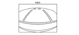
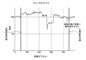
ところで、従来、駐車枠検出装置においては、図27の入力画像に示すように、駐車場101のコンクリートの灰色の路面102に黄色やオレンジ色等で描かれた駐車枠線103にあっては、横方向に直線の計測ラインL上でラインプロファイル(輝度変化)を測定した場合に、図28のラインプロファイル(輝度変化)に示すように、路面102と左側駐車枠線・右側駐車枠線に明確な輝度(予め設定された閾値を超える程度の輝度)の差が無いため(この例として、黄色やオレンジ色の駐車枠線103は、灰色の路面102よりも輝度が低い)、駐車枠線103の抽出ができない問題があった。
また、図29には、駐車枠線のエッジを検出した従来例を示すが、エッジが十分に検出されていないことがわかる。
更に、上記の特許文献1では、駐車枠線が白線で描かれていると定義し、また、上記の特許文献2では、駐車枠線のエッジの検出において、「画像処理部は、カメラ画像データのエッジ強度やエッジ形状と、予め求めておいた駐車枠線を示すエッジ強度やエッジ形状とを比較して、エッジを検出する」としているため、予め求めていない未知の駐車枠線の抽出には対応することができないという不都合があった。
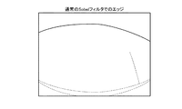
更にまた、図30に示す通常のSobelフィルタだけでは、駐車枠線のエッジを十分に検出することができなかった。
By the way, in the conventional parking frame detection device, as shown in the input image of FIG. 27, in the
FIG. 29 shows a conventional example in which the edge of the parking frame line is detected, but it is understood that the edge is not sufficiently detected.
Furthermore, in the above-mentioned
Furthermore, the edge of the parking frame line could not be detected sufficiently with only the ordinary Sobel filter shown in FIG.
そこで、この発明の目的は、駐車枠線のエッジの検出の際の閾値の決定手段(適応制御的なもの)を不要とし、処理を簡素化して、駐車枠線の両端に生じるエッジを路面の模様、影、照明等の影響を極力排除して信頼性を高くし、路面と駐車枠線との輝度差が少ない場合にも、安定した駐車枠の検出を行うことができる駐車枠検出装置を提供することにある。 Therefore, an object of the present invention is to eliminate the need for threshold value determination means (adaptive control type) when detecting the edge of the parking frame line, simplify the processing, and remove edges generated at both ends of the parking frame line on the road surface. A parking frame detection device that eliminates the effects of patterns, shadows, lighting, etc. as much as possible to increase reliability, and can stably detect parking frames even when there is little difference in brightness between the road surface and parking frame lines It is to provide.
この発明は、車両周囲を撮像する撮像手段と、この撮像手段により撮像した画像から駐車枠を検出する制御手段とを設けた駐車枠検出装置において、前記制御手段は、前記撮像手段により撮像した画像のRGB信号に基づいて前記画像上の黄色系部分を抽出する黄色系抽出手段と、この黄色系抽出手段により抽出された黄色系部分の画素の輝度に予め設定された値を加算する輝度加算手段とを備え、この輝度加算手段により予め設定された値を加算された画像から駐車枠を検出することを特徴とする。 The present invention relates to a parking frame detection apparatus provided with an imaging means for imaging the periphery of a vehicle and a control means for detecting a parking frame from an image captured by the imaging means, wherein the control means is an image captured by the imaging means. A yellow color extracting means for extracting a yellow color portion on the image based on the RGB signal, and a luminance adding means for adding a preset value to the luminance of the pixel of the yellow color portion extracted by the yellow color extraction means And a parking frame is detected from an image added with a preset value by the luminance adding means.
この発明の駐車枠検出装置は、駐車枠線のエッジの検出の際の閾値の決定手段(適応制御的なもの)を不要とし、処理を簡素化して、駐車枠線の両端に生じるエッジを路面の模様、影、照明等の影響を極力排除して信頼性を高くし、路面と駐車枠線との輝度差が少ない場合にも、安定した駐車枠の検出を行うことができる。 The parking frame detection device of the present invention eliminates the need for threshold value determination means (adaptive control type) when detecting the edge of the parking frame line, simplifies the processing, and detects the edges generated at both ends of the parking frame line on the road surface. Even when the influence of the pattern, shadow, lighting, etc. is eliminated as much as possible to increase reliability and the difference in brightness between the road surface and the parking frame line is small, stable parking frame detection can be performed.
この発明は、駐車枠線のエッジの検出の際の閾値の決定手段(適応制御的なもの)を不要とし、処理を簡素化して、駐車枠線の両端に生じるエッジを路面の模様、影、照明等の影響を極力排除して信頼性を高くし、路面と駐車枠線との輝度差が少ない場合にも、安定した駐車枠の検出を行う目的を、撮像した画像の輝度信号と色差信号とからRGB信号へ変換し、このRGB信号に基づいて画像上の黄色系部分を抽出し、この黄色系部分の画素の輝度に予め設定された値を加算し、この加算された画像から駐車枠を検出して実現するものである。 The present invention eliminates the need for threshold determination means (adaptive control type) when detecting the edge of the parking frame line, simplifies the processing, and removes the edges generated at both ends of the parking frame line from the road surface pattern, shadow, The luminance signal and color difference signal of the captured image are used for the purpose of stable parking frame detection even when the luminance difference between the road surface and the parking frame line is small by eliminating the influence of lighting etc. as much as possible. Are converted into RGB signals, a yellow portion on the image is extracted based on the RGB signals, a preset value is added to the luminance of the pixels of the yellow portion, and a parking frame is added from the added image. It is realized by detecting.
図1〜図23は、この発明の実施例1を示すものである。
図3において、1は車両、2は駐車場である。
この駐車場2は、コンクリートであり、灰色の路面3を有する。
この駐車場2の路面3には、駐車枠(駐車スペース)4が区画されている。
この駐車枠4は、車両1の駐車範囲を区画する駐車枠線5として、長手方向の平行な左側駐車枠線(黄色線又はオレンジ色線)6・右側駐車枠線(黄色線又はオレンジ色線)7と、この左側駐車枠線6・右側駐車枠線7の左前側端部・右前側端部とを繋いで左側駐車枠線6・右側駐車枠線7に対して直交する短手方向の前側駐車枠線(黄色線又はオレンジ色線)8とで、形成される。
また、駐車枠4には、後方部で、輪止めとして、左右の輪止め9・10が直列で短手方向に配設されている。
1 to 23
In FIG. 3, 1 is a vehicle and 2 is a parking lot.
The parking lot 2 is made of concrete and has a
A parking frame (parking space) 4 is defined on the
The
In addition, the
車両1には、駐車枠検出装置11が搭載される。
この駐車枠検出装置11は、図2に示すように、車両周囲を撮像する超広角の撮像手段(カメラ)12と、この撮像手段12に連絡した画像記録手段13と、この画像記録手段13に連絡した制御手段14とを備えている。
撮像手段12は、車両1の後部に取り付けた超広角のバックカメラ等の撮像機器からなり、車両周囲を撮像する。
画像記録手段13は、ビデオデコーダ等の記録機器からなり、撮像手段12により撮像した画像を記録するとともに制御手段14に出力する。
A parking
As shown in FIG. 2, the parking
The imaging means 12 is composed of an imaging device such as a super-wide-angle back camera attached to the rear part of the
The
制御手段14は、撮像手段12により撮像した画像から駐車枠線5を抽出して駐車枠4を検出するものであって、撮像手段12により撮像した画像の輝度信号と色差信号とからRGB(レッド グリーン ブルー)信号へ変換するRGB変換手段14Aと、撮像手段12により撮像した画像のRGB信号に基づいて前記画像上の黄色系部分を抽出する黄色系抽出手段14Bと、この黄色系抽出手段14Bにより抽出された黄色系部分の画素の輝度に予め設定された値を加算する輝度加算手段14Cとを備え、この輝度加算手段14Cにより予め設定された値を加算された画像から駐車枠4を検出する。
また、前記黄色系抽出手段14Bは、RGB変換手段14Aにより変換されたRGB信号のR値がB値よりも大きく、かつ、G値がB値よりも大きく、かつ、R値からB値を減算した値が予め設定された値よりも大きい画素を黄色系部分として抽出する。
The
Further, the yellow color extracting means 14B is such that the R value of the RGB signal converted by the
次に、この実施例に係る黄色やオレンジ色の駐車枠線5の抽出のために色情報を併せて用いる方法を説明する。
一般に、従来の図27のような灰色の路面102と黄色の駐車枠線103との輝度情報に顕著な差が無く、色情報のみ異なる場合に、隣接画素との色情報の違いを検出し、同一色の領域の抽出を行う手法が知られている。
しかし、実際の屋外の環境では、日光や照明等の条件により、例えば、暗所では、黄色でも、茶色に近い色に見え、また、明るい時は、白色に近い色となる。このため、撮像手段にて撮影された画像よりRの成分、Gの成分、Bの成分に分離して映像信号を確認しても、駐車枠線をきれいに抽出することが困難である。
例えば、夜間、周囲が暗い中で駐車枠線の一部に照明が当たっている場合、撮像手段のオートゲインコントロール等の影響により、R成分が飽和することがあるため、Rの成分、Gの成分、Bの成分の比率等は一定しない。
また、黄色は、理想的には、(R、G、B)=(255、212、0)であるが、実際の映像では、B値が、R値、G値に比べ極端に小さくなることは少ない。このため、単に事前に設定した色情報のみを用いて黄色の駐車枠線のエッジを抽出しようとすると、難しいものである。
例として、図27のラインプロファイル(輝度変化)をR値、G値、B値について計測したものを、図4に示す。
この図4において、左側駐車枠線・右側駐車枠線以外では、R値、G値、B値が略一致しているが、左側駐車枠線・右側駐車枠線では、R値とG値とB値の大小関係(R値が最も大きく、次いで、G値、B値が最も小さい)は同じであるが、その比や値は一定しておらず、また、R値、G値、B値、それぞれに範囲を設けることで、黄色系の色を抽出することは困難であることが確認できる。そのため、一定範囲のR値、G値、B値等の条件を用いて黄色の駐車枠線を抽出することは、困難である。
そこで、黄色やオレンジ色の駐車枠線であるので、R値とG値とはB値よりも大きいという条件と、R値とB値との差が第一の閾値以上であることを条件とした駐車枠線の抽出のための補正手法を提案する。
Next, a method of using color information together for extracting the yellow or
In general, when there is no significant difference in luminance information between the
However, in an actual outdoor environment, depending on conditions such as sunlight and lighting, for example, in a dark place, it looks yellow or even a color close to brown, and when it is bright, it becomes a color close to white. For this reason, it is difficult to extract the parking frame line neatly even if the video signal is confirmed after being separated into an R component, a G component, and a B component from the image captured by the imaging unit.
For example, when a part of a parking frame line is illuminated at night when the surroundings are dark, the R component may be saturated due to the influence of auto gain control of the imaging means, etc. The ratio of the component and the component of B is not constant.
Also, yellow is ideally (R, G, B) = (255, 212, 0), but in an actual video, the B value is extremely smaller than the R value and the G value. There are few. For this reason, it is difficult to extract the edge of the yellow parking frame line using only color information set in advance.
As an example, FIG. 4 shows the line profile (luminance change) of FIG. 27 measured for the R value, G value, and B value.
In FIG. 4, the R value, the G value, and the B value are substantially the same except for the left parking frame line and the right parking frame line. However, in the left parking frame line and the right parking frame line, the R value and the G value are The B value magnitude relationship (R value is largest, then G value, B value is smallest) is the same, but the ratio and value are not constant, and R value, G value, B value By providing a range for each, it can be confirmed that it is difficult to extract a yellowish color. Therefore, it is difficult to extract a yellow parking frame line using conditions such as a certain range of R value, G value, and B value.
Therefore, since the parking frame line is yellow or orange, the condition that the R value and the G value are larger than the B value, and the condition that the difference between the R value and the B value is greater than or equal to the first threshold value. We propose a correction method for extracting the parking frame line.
ここで、図4に示すように、オレンジ色の駐車枠線にて、R>B、R>G、G>Bであることがわかる。
この条件により、先ず、R>B、G>Bを条件として、駐車枠線を抽出することを考える。
R>Gを使用しないのは、理想的には、黄色は、(R、G、B)=(255、212、0)であり、R>Gであるが、R=Gや、R<Gの領域でも黄色く見える場合が存在するため、ここでは、除外する。
例えば、図4における左右の駐車枠線上のR値、G値、B値を確認すると、B値は零(0)に近い値となっておらず、「170」程度の高い値になっていることがわかる。これは、図25では、画面全体が明るく白っぽいことから、R値、G値、B値のそれぞれの値に白色側でバイアスがかかった状態となっているためである。
また、R>B、G>Bの条件のみでは、白色、灰色、黒色等で、略R値、G値、B値が等しい色の領域にて、誤った領域が抽出されるため、問題がある。
そこで、図27におけるR値、G値、B値毎に分離した画像のうち、R値とB値に関するものと、その差分画像を、図5〜図7に示す。
図7では、駐車枠線の部分が周囲に比べ白っぽくなっていることがわかる。
そこで、図7中の直線(横方向)の計測ラインL上のラインプロファイル(輝度変化)を計測すると、図8のようになっていることがわかる。
Here, as shown in FIG. 4, it is understood that R> B, R> G, and G> B in the orange parking frame line.
Based on these conditions, first, it is considered to extract a parking frame line on condition that R> B and G> B.
R> G is not used. Ideally, yellow is (R, G, B) = (255, 212, 0) and R> G, but R = G or R <G This area is excluded here because it may appear yellow even in the area of.
For example, when the R value, the G value, and the B value on the left and right parking frame lines in FIG. 4 are confirmed, the B value is not close to zero (0) and is a high value of about “170”. I understand that. This is because, in FIG. 25, since the entire screen is bright and whitish, the R value, G value, and B value are biased on the white side.
Also, under the conditions of R> B and G> B only, an erroneous region is extracted in a region of white, gray, black, etc., with colors having substantially the same R value, G value, and B value. is there.
Therefore, among the images separated for each of the R value, G value, and B value in FIG. 27, those relating to the R value and the B value and the difference image thereof are shown in FIGS.
In FIG. 7, it can be seen that the portion of the parking frame line is whitish compared to the surrounding area.
Therefore, when the line profile (luminance change) on the measurement line L in the straight line (lateral direction) in FIG. 7 is measured, it can be seen that FIG. 8 is obtained.
この図8では、左右の駐車枠線の部分に、輝度値50程度のピークP・Pが現れていることがわかる。
そこで、差分結果としての|R−B|(絶対値)が第一の閾値よりも大きいという条件を追加し、駐車枠線の抽出を行う。
先に、R>Bという条件があるため、|R−B|>(第一の閾値)、又は、|R−B|≧(第一の閾値)とすることも可能である。
ここで、第一の閾値を「15」とした場合に、図25に、R>B、G>B、|R−B|>(第一の閾値)での判定処理を適用した。この抽出結果を、図9に示す。
この図9では、一部異なった箇所も抽出されているが、直線状ではないため、後のハフ変換等の直線認識処理や孤立点除去にて排除される。
ここで、上記の条件、R>B、G>B、|R−B|>(第一の閥値)を、一般的なコンクリートの路面に白線が描かれている場合について適用すると、図10(A)、図10(B)のようになる。
In FIG. 8, it can be seen that peaks P and P having a luminance value of about 50 appear in the left and right parking frame portions.
Therefore, a condition that | R−B | (absolute value) as a difference result is larger than the first threshold is added, and a parking frame line is extracted.
Since there is a condition of R> B first, | R−B |> (first threshold value) or | R−B | ≧ (first threshold value) can be set.
Here, when the first threshold value is “15”, the determination processing with R> B, G> B, and | R−B |> (first threshold value) is applied to FIG. 25. The extraction result is shown in FIG.
In FIG. 9, a part that is partially different is also extracted, but is not linear, and is eliminated by subsequent straight line recognition processing such as Hough transform or isolated point removal.
Here, when the above conditions, R> B, G> B, | R−B |> (first threshold value) are applied to a case where a white line is drawn on a general concrete road surface, FIG. (A) and FIG. 10 (B) are obtained.
この図10(B)より、このような手法では、白線が抽出できない(白線の検出には影響しない)ことがわかる。
しかし、白線の場合は、従来手法等で、隣接画素との輝度値の比較等の処理にてエッジの抽出が可能である。黄色系の駐車枠線についても、白線と同様の処理でエッジ抽出が可能なように工夫を行う。
黄色系の駐車枠線が従来の白線に適用したエッジの抽出手法にてエッジの抽出が行えない理由は、図28に示したように、駐車枠線と背景(路面)の間の輝度差が少ないことに起因している。
つまり、黄色系の駐車枠線が周囲に比べ十分に明るく(輝度値が高い)なれば、従来と同様の輝度値を用いたエッジ検出が適用できる。
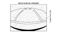
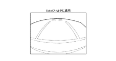
そこで、この実施例では、図11のように、抽出された黄色系の駐車枠線の輝度値(YCbCrにおけるY値)に一定の値を加算する。ここでは、エッジ検出処理を、隣接画素値との差分により行う。
例として、その閾値を「10」としたときの3倍程度の「30」を、輝度値に加算する。これは、図8に示したように、この実施例によって抽出される黄色系の駐車枠線は、その輝度値が一定ではなくピークP・Pを持つため、第一の閾値以上となった領域全てを周囲(路面)に対して十分に明るくするためである。
輝度値を加算した結果を、図11に示す。この図11を用いて隣接画素値との差分を用いたエッジ抽出結果を、図12に示す。
この図12より、図29と比較して駐車枠線のエッジが検出できていることが確認できる。なお、この場合、具体的な各閾値は、使用する撮像手段(カメラ)、画像記録機器(ビデオデコーダ)の特性等により変化するため、それらに合わせて調整が必要である。
From FIG. 10B, it can be seen that such a method cannot extract a white line (does not affect the detection of the white line).
However, in the case of a white line, an edge can be extracted by a process such as comparison of luminance values with adjacent pixels by a conventional method or the like. The yellow parking frame line is also devised so that the edge can be extracted by the same process as the white line.
The reason why the yellow parking frame line cannot be extracted by the edge extraction method applied to the conventional white line is that the luminance difference between the parking frame line and the background (road surface) is as shown in FIG. This is due to the fact that there are few.
That is, if the yellow parking frame line is sufficiently brighter (the brightness value is higher) than the surroundings, edge detection using the same brightness value as in the past can be applied.
Therefore, in this embodiment, as shown in FIG. 11, a certain value is added to the luminance value (Y value in YCbCr) of the extracted yellow parking frame line. Here, the edge detection process is performed based on the difference from the adjacent pixel value.
As an example, “30”, which is about three times the threshold value “10”, is added to the luminance value. This is because, as shown in FIG. 8, the yellow parking frame line extracted by this embodiment has a peak value P / P rather than a constant luminance value, so that the region is equal to or higher than the first threshold value. This is to make everything bright enough for the surroundings (road surface).
The result of adding the luminance values is shown in FIG. FIG. 12 shows an edge extraction result using a difference from an adjacent pixel value using FIG.
From FIG. 12, it can be confirmed that the edge of the parking frame line can be detected as compared with FIG. In this case, the specific threshold values vary depending on the characteristics of the imaging means (camera) to be used, the image recording device (video decoder), etc., and need to be adjusted accordingly.
この実施例に係る検出処理において、図10(A)、図10(B)に示した白色の駐車枠線に適用した場合のエッジ検出結果を、図13に示す。この図13では、エッジ検出に悪影響が無いことが確認できる。
ここで、R>B、G>B、|R−B|>(第一の閥値)という条件は、黄色から赤色にかけての色を含む領域が抽出することとなる。通常、駐車枠線として路面に赤い線が描かれていることは稀なため、上記の条件で目的を達成できるが、赤色が抽出されることで不具合が生じる場合は、|R−G|<(第2の閾値)の条件を設けても良い。これは、黄色ではR値とG値が略等しく、赤色に近づくにつれて、R値がG値に対し大きくなることを利用したものである。
FIG. 13 shows an edge detection result when the detection process according to this embodiment is applied to the white parking frame line shown in FIGS. 10 (A) and 10 (B). In FIG. 13, it can be confirmed that there is no adverse effect on edge detection.
Here, the conditions of R> B, G> B, and | R−B |> (first threshold value) result in the extraction of a region including colors from yellow to red. Usually, since it is rare that a red line is drawn on the road surface as a parking frame line, the purpose can be achieved under the above conditions, but if a problem occurs due to the extraction of red, | R−G | < A condition (second threshold) may be provided. This uses the fact that the R value and the G value are substantially equal in yellow, and that the R value increases with respect to the G value as it approaches red.
次に、この実施例に係る駐車枠の検出についてを、以下にさらに具体的に説明する。
撮像手段12より出力されるNTSC信号を画像記録機器13にて、ITU−R BT.601(国際電気通信連合 無線通信部門)等の規格にあったデジタル信号に変換する。画像記録機器13のデコーダからの出力信号は、一般に、YCbCrとなっている。このYCbCr信号は、輝度信号Yと、色差信号Cb、Crとからなる。
ここで、先に挙げた条件、R>B、G>B、|R−B|>(第一の閾値)を適用するために、YCbCr信号よりRGB信号への変換を行う。
このRGB信号への変換式は、
ITU−R BT.601より、
R=Y+1.40200*Cr
G=Y−0.34414*Cb−0.71414*Cr
B=Y+1.77200*Cb
である。
また、ITU−R BT.601より、YCbCr信号の値は、デジタル8bitで表されるが、0〜255ではなく、Yは16〜235、CbCrは16〜240、一方、RGB信号は0〜255で表されるため、フルスケールに対する変換が必要である。
この実施例では、必ずしも正確なRGB値が必要ではなく、RGB値の大小関係やR値とB値との差が検出できれば良いため、厳密に、YCbCr信号からRGB信号への変換の必要がなく、より簡略化した変換でかまわない。
例えば、
R=Y+1.5Cr
G=Y−0.25Cb−0.75Cr
B=Y+1.5Cb
とし、第一の閾値を「15」程度としても、同様の結果が得られる。
上記のように、式を簡略化することにより、係数を「0.5」や「0.25」、「0.75」、「1.5」等にすることができるため、また、ビットシフトと加算のみで演算ができるため、処理に時間のかかる除算を使用しなくても良いメリットがある。
また、RGB信号と異なり、YCbCr信号では、各画素の輝度値Yに対し、色差Cb、Crは隣接画素と共通として扱うため、Cb0、Y0、Cr0、Y1、Cb1、Y2のように出力されるため、Cb0、Y0、Cr0、Y1の単位で取り扱う必要がある。Y1はY0と共通のCr0を用いるが、Cbは、Y0と共通ではなく、Y1の次に出力されるCb1を使用する。このため、RGB信号への変換及び黄色系の駐車枠線の抽出処理は、Cb0、Y0、Cr0について行い、その結果を受けて、輝度値の加算処理をY0、Y1に対して共通に行う。
Y0、Y1が共に、輝度値の加算を行わないと、後のエッジ検出処理にてY0とY1との間に本来無いエッジが抽出されてしまう問題が生じる。
しかし、Y0、Y1が共に、輝度値の加算を行うことにより、黄色系の領域全ての輝度値が高くなるため、図12に示すように、その輪郭にエッジが検出されることとなる。
なお、上記の処理は、Cb0、Y0、Cr0とCr0、Y1、Cb1のように、厳密に行ってもよい。
Next, the detection of the parking frame according to this embodiment will be described more specifically below.
The NTSC signal output from the imaging means 12 is transmitted to the ITU-R BT. 601 (International Telecommunication Union Radiocommunication Sector), etc. The output signal from the decoder of the
Here, in order to apply the above-described conditions, R> B, G> B, | R−B |> (first threshold value), conversion from the YCbCr signal to the RGB signal is performed.
The conversion formula to this RGB signal is
ITU-R BT. From 601
R = Y + 1.40200 * Cr
G = Y−0.34414 * Cb−0.71414 * Cr
B = Y + 1.77200 * Cb
It is.
Also, ITU-R BT. From 601, the value of the YCbCr signal is represented by digital 8 bits, but it is not 0-255, but Y is 16-235, CbCr is 16-240, while the RGB signal is represented by 0-255. Conversion to scale is required.
In this embodiment, accurate RGB values are not necessarily required, and it is only necessary to detect the magnitude relationship of RGB values and the difference between the R value and the B value. Therefore, it is not necessary to strictly convert the YCbCr signal to the RGB signal. A simpler conversion can be used.
For example,
R = Y + 1.5Cr
G = Y-0.25Cb-0.75Cr
B = Y + 1.5Cb
Even if the first threshold is set to about “15”, the same result can be obtained.
As described above, by simplifying the equation, the coefficient can be set to “0.5”, “0.25”, “0.75”, “1.5”, etc. Therefore, there is an advantage that it is not necessary to use division that takes time for processing.
Unlike the RGB signal, the YCbCr signal is output as Cb0, Y0, Cr0, Y1, Cb1, and Y2 because the color differences Cb and Cr are handled in common with the adjacent pixels with respect to the luminance value Y of each pixel. Therefore, it is necessary to handle in units of Cb0, Y0, Cr0, Y1. Y1 uses Cr0 which is common to Y0, but Cb is not common to Y0 and uses Cb1 output next to Y1. For this reason, conversion to RGB signals and yellow parking frame line extraction processing are performed for Cb0, Y0, and Cr0, and in response to the result, luminance value addition processing is performed in common for Y0 and Y1.
If luminance values are not added to both Y0 and Y1, there is a problem that an edge that is not originally between Y0 and Y1 is extracted in the subsequent edge detection processing.
However, by adding luminance values for both Y0 and Y1, the luminance values of all yellow areas are increased, so that an edge is detected in the contour as shown in FIG.
In addition, you may perform said process exactly like Cb0, Y0, Cr0 and Cr0, Y1, Cb1.
また、隣接画素との差分によりエッジを抽出する理由について、以下のように、考案過程を併せて説明する。
従来手法の処理例として、白線両端微分値強調フィルタを用いた方法を以下に示す。これは、画像の微分を求め、白線両端微分値強調フィルタを用いて道路の白線幅と同じ幅を持つ白線の抽出を行っている。
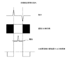
ここで、微分は差分で置き換え可能であるので、図14(A)の差分オペレータを用いて差分画像を得る。
白線両端微分値強調フィルタは、道路白線幅(画素数)と同じ幅を持つオペレータであり、図14(B)に示すように、オペレータの幅の中央で符号が反転する。
以上の処理により、図15のような結果が得られる。よって、適切な閾値を選択することにより、道路上の白線と同じ幅を持つ特徴のみを抽出することができる。この閾値の選択には、判別分析法等を用いる。
従来技術で用いられている微分(差分)処理については、同様に走査線方向(画面横方向)での差分処理とする。
しかし、白線両端微分値強調フィルタを用いるためには、画像(走査線)を一度記憶手段(メモリ)に記録する必要があるため、その分のリソースが必要となる。また、白線両端微分値強調フィルタを用いると、図15のように、閾値のレベルが変動するため、画像の各位置に応じて閾値を適応制御する必要がある。そのためには、判別分析法等の処理が必要となるが、これらの処理は、非常に重く、また、並列処理する場合も膨大なリソースが必要となる。
そこで、「差分画像は、すぐ隣の画素との差分であり、隣接画素と当該画素の明るさ(照明条件)が大きく異なることは稀である」(例外:影によるエッジ)こと、また、一般に、駐車枠に引かれた白線等の駐車枠線は、運転者が識別しやすいよう、路面とコントラストがはっきりしていると考えられるため、閾値は一定値とすることとした。
図16〜図19には、処理前の画像及び閾値を「1」、「10」、「20」としたときのエッジ検出結果を示す。この場合、エッジの極性による区別なく(白→黒、黒→白)全て表示している。
図17の閾値「1」では、細かなテクスチャ(凹凸にライトが反射)によるエッジによる影響が見られるが、図18の閾値「10」、図19の閾値「20」では、良好な結果が得られている。
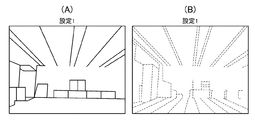
ここで、輝度変化による影響を確認するため、図18の閾値「10」にて、レンズの絞りを変化させたときの結果を、図20〜図22に示す。この図20〜図22では、ダイナミックレンジの1/4程度の暗さまでは対応可能であることがわかる。
ここで、図22の「設定3」の場合、画像奥の壁に近づくにつれ、エッジの検出ができなくなっているが、仮に閾値を「5」まで下げた場合、エッジの検出はできるが、ノイズによる影響が大きくなってしまう(図23参照)。このことより、この手法の閾値の決定に判別分析法を用いても効果が少ないことが、確認できる。
Further, the reason for extracting the edge based on the difference from the adjacent pixel will be described together with the idea process as follows.
As a processing example of the conventional method, a method using a white line double-ended differential value enhancement filter is shown below. In this method, the differentiation of the image is obtained, and a white line having the same width as the white line width of the road is extracted using a white line both-end differential value enhancement filter.
Here, since differentiation can be replaced with a difference, a difference image is obtained using the difference operator of FIG.
The white line both end differential value enhancement filter is an operator having the same width as the road white line width (number of pixels), and the sign is inverted at the center of the operator width as shown in FIG.
With the above processing, a result as shown in FIG. 15 is obtained. Therefore, by selecting an appropriate threshold, only features having the same width as the white line on the road can be extracted. A discriminant analysis method or the like is used for selection of the threshold value.
Similarly, the differential (difference) processing used in the conventional technology is the differential processing in the scanning line direction (screen horizontal direction).
However, in order to use the white line both-end differential value emphasis filter, it is necessary to once record an image (scanning line) in a storage means (memory), so that resource is required. Further, when the white line both-end differential value emphasis filter is used, the threshold level fluctuates as shown in FIG. 15. Therefore, it is necessary to adaptively control the threshold according to each position of the image. For this purpose, processing such as discriminant analysis is required. However, these processing are very heavy, and enormous resources are required even in parallel processing.
Therefore, “the difference image is the difference between the adjacent pixels, and it is rare that the brightness (illumination condition) of the adjacent pixels and the pixel is greatly different” (exception: edge by shadow), and generally Since the parking frame line such as the white line drawn on the parking frame is considered to have a clear contrast with the road surface so that the driver can easily identify it, the threshold value is set to a constant value.
16 to 19 show the edge detection results when the images before processing and the threshold values are “1”, “10”, and “20”. In this case, all are displayed (white → black, black → white) regardless of the polarity of the edge.
The threshold “1” in FIG. 17 shows the influence of the edge due to the fine texture (the light is reflected on the unevenness). However, the threshold “10” in FIG. 18 and the threshold “20” in FIG. It has been.
Here, in order to confirm the influence of the luminance change, the results when the lens aperture is changed at the threshold value “10” in FIG. 18 are shown in FIGS. In FIGS. 20 to 22, it can be seen that it is possible to cope with darkness of about ¼ of the dynamic range.
Here, in the case of “Setting 3” in FIG. 22, the edge cannot be detected as it approaches the wall at the back of the image. However, if the threshold value is lowered to “5”, the edge can be detected, but the noise can be detected. Will increase the influence (see FIG. 23). From this, it can be confirmed that even if the discriminant analysis method is used to determine the threshold value of this method, the effect is small.
次に、この実施例に係る駐車枠検出の制御を、図1のフローチャートに基づいて説明する。
図1に示すように、制御手段14でプログラムが開始すると(ステップA01)、撮像手段12が車両後方の画像を撮像し、この撮像手段12により撮像された画像を記録し、そして、その画像の信号としての映像信号(YCbCr)を入力し(ステップA02)、RGB信号に変換する(ステップA03)。
そして、RGB信号のR値がB値よりも大きく、かつ、G値がB値よりも大きいか否かを判断する(ステップA04)。
このステップA04がYESの場合には、|R−B|>第一の閾値か否かを判断する(ステップA05)。
このステップA05がYESの場合には、輝度値へ予め設定された一定の値を加算する(ステップA06)。
このステップA06の処理後、前記ステップA04がNOの場合、又は、前記ステップA05がNOの場合には、プログラムをエンドとする(ステップA07)。
Next, parking frame detection control according to this embodiment will be described based on the flowchart of FIG.
As shown in FIG. 1, when the program is started by the control means 14 (step A01), the image pickup means 12 picks up an image behind the vehicle, records the image picked up by the image pickup means 12, and A video signal (YCbCr) as a signal is input (step A02) and converted into an RGB signal (step A03).
Then, it is determined whether the R value of the RGB signal is larger than the B value and the G value is larger than the B value (step A04).
If this step A04 is YES, it is determined whether or not | R−B |> first threshold value (step A05).
If this step A05 is YES, a predetermined value is added to the luminance value (step A06).
After step A06, if step A04 is NO, or if step A05 is NO, the program is ended (step A07).
図24、図25は、この発明の実施例2を示すものである。
この実施例2においては、上述の実施例1と同一機能を果たす箇所には、同一符号を付して説明する。
上述の実施例1の駐車枠検出装置1においては、画像記録手段13のビデオデコーダからの出力信号は、YCbCrとなっている。しかし、ビデオデコーダによっては、RGB出力となっているものもある。
図25に示すように、この実施例2の駐車枠検出装置1においては、画像記録手段13のビデオデコーダからの出力信号は、RGBとなっている。
従って、制御手段14では、撮像手段12により撮像した画像のRGB信号に基づいて前記画像上の黄色系部分を抽出する黄色系抽出手段14Bと、撮像手段12により撮像した画像のRGB信号からYCbCr信号へ変換するYCbCr変換手段14Dと、このYCbCr変換手段14Dにより変換された画像に対して黄色系抽出手段14Bにより抽出された黄色系部分の画素の輝度に予め設定された値を加算する輝度加算手段14Cとを備え、この輝度加算手段14Cにより予め設定された値を加算された画像から駐車枠4を検出する。
24 and 25 show Embodiment 2 of the present invention.
In the second embodiment, portions that perform the same functions as those of the first embodiment will be described with the same reference numerals.
In the parking
As shown in FIG. 25, in the parking
Therefore, the control means 14 extracts a yellowish-colored extraction means 14B for extracting a yellowish-colored portion on the image based on the RGB signals of the image taken by the imaging means 12, and a YCbCr signal from the RGB signals of the image taken by the imaging means 12. YCbCr converting means 14D for converting to YCbCr, and luminance adding means for adding a preset value to the luminance of the yellow portion pixel extracted by the yellow extracting means 14B to the image converted by the YCbCr converting means
次に、この実施例2に係る駐車枠検出の制御を、図24のフローチャートに基づいて説明する。
図24に示すように、制御手段14においてプログラムがスタートすると(ステップB01)、撮像手段12が車両後方の画像を撮像し、この撮像手段12により撮像された画像を記録し、そして、その画像の信号としての映像信号(RGB)を入力する(ステップB02)。
そして、このRGB信号のR値がB値よりも大きく、かつ、G値がB値よりも大きいか否かを判断する(ステップB03)。
このステップB03がYESの場合には、|R−B|>第一の閾値か否かを判断する(ステップB04)。
このステップB04がYESの場合には、YCbCr信号に変換し(ステップB05)、輝度値へ予め設定された一定の値を加算する(ステップB06)。
このステップB06の処理後、前記ステップB03がNOの場合、又は、前記ステップB04がNOの場合には、プログラムをエンドとする(ステップB07)。
Next, parking frame detection control according to the second embodiment will be described based on the flowchart of FIG.
As shown in FIG. 24, when the program is started in the control means 14 (step B01), the image pickup means 12 picks up an image behind the vehicle, records the image picked up by the image pickup means 12, and A video signal (RGB) as a signal is input (step B02).
Then, it is determined whether or not the R value of the RGB signal is larger than the B value and the G value is larger than the B value (step B03).
If this step B03 is YES, it is determined whether or not | R−B |> first threshold value (step B04).
If this step B04 is YES, it is converted into a YCbCr signal (step B05), and a predetermined value is added to the luminance value (step B06).
After step B06, if the step B03 is NO or if the step B04 is NO, the program is ended (step B07).
以上、この発明の実施例について説明してきたが、上述の実施例の構成を請求項毎に当てはめて説明する。
先ず、請求項1に記載の発明において、制御手段14は、撮像手段12により撮像した画像のRGB信号に基づいて前記画像上の黄色系部分を抽出する黄色系抽出手段14Bと、この黄色系抽出手段14Bにより抽出された黄色系部分の画素の輝度に予め設定された値を加算する輝度加算手段14Cとを備え、この輝度加算手段14Cにより予め設定された値を加算された画像から駐車枠を検出する。
これにより、コンクリートの路面3に黄色やオレンジ色で描かれた駐車枠線5を抽出することができる。さらに、白色で描かれた駐車枠線に対する処理と区別することなく、従来のエッジ検出により駐車枠4を検出することができる。
請求項2に記載の発明において、黄色系抽出手段14Bは、RGB信号のR値がB値よりも大きく、かつ、G値がB値よりも大きく、かつ、R値からB値を減算した値が予め設定された値よりも大きい画素を黄色系部分として抽出する。
これにより、コンクリートの路面3上に描かれた黄色やオレンジ色の駐車枠線5を精度よく抽出することができる。
Although the embodiments of the present invention have been described above, the configuration of the above-described embodiments will be described for each claim.
First, in the first aspect of the present invention, the
Thereby, the
In the invention according to claim 2, the yellow color extracting means 14B is a value obtained by subtracting the B value from the R value and the R value of the RGB signal is larger than the B value, the G value is larger than the B value. A pixel having a value larger than a preset value is extracted as a yellowish portion.
Thereby, the yellow or orange
図26は、この発明の変形例を示すものである。
この変形例では、差分によるエッジの検出ではなく、通常のSobelファイル等にも適用できる。つまり、図30の通常のSobelファイルだけでは、エッジを確認できないが、図26では、Sobelファイルにこの実施例に係る検出方法を用いることにより、駐車枠線のエッジを検出できていることがわかる。
FIG. 26 shows a modification of the present invention.
This modification can be applied not only to edge detection based on a difference but also to a normal Sobel file. That is, the edge cannot be confirmed only with the normal Sobel file in FIG. 30, but in FIG. 26, it can be seen that the edge of the parking frame line can be detected by using the detection method according to this embodiment in the Sobel file. .
この発明の駐車枠検出装置は、運転者に適切な画像を提供させるものであり、各種車両に適用できる。 The parking frame detection device according to the present invention allows a driver to provide an appropriate image and can be applied to various vehicles.
1 車両
2 駐車場
3 駐車場の路面
4 駐車枠(駐車スペース)
5 駐車枠線
6 左側駐車枠線
7 右側駐車枠線
8 前側駐車枠線
11 駐車枠検出装置
12 撮像手段
13 映像記録機器
14 制御手段
14A RGB変換手段
14B 黄色系抽出手段
14C 輝度加算手段
1 Vehicle 2
DESCRIPTION OF
Claims (2)
この撮像手段により撮像した画像から駐車枠を検出する制御手段とを設けた駐車枠検出装置において、前記制御手段は、前記撮像手段により撮像した画像のRGB信号に基づいて前記画像上の黄色系部分を抽出する黄色系抽出手段と、この黄色系抽出手段により抽出された黄色系部分の画素の輝度に予め設定された値を加算する輝度加算手段とを備え、この輝度加算手段により予め設定された値を加算された画像から駐車枠を検出することを特徴とする駐車枠検出装置。 Imaging means for imaging the surroundings of the vehicle;
In the parking frame detection apparatus provided with a control unit for detecting a parking frame from an image captured by the imaging unit, the control unit is configured to display a yellowish portion on the image based on an RGB signal of the image captured by the imaging unit. And a luminance adding means for adding a preset value to the luminance of the pixels of the yellow portion extracted by the yellow extracting means. The luminance adding means A parking frame detection device for detecting a parking frame from an image to which a value is added.
Priority Applications (1)
| Application Number | Priority Date | Filing Date | Title |
|---|---|---|---|
| JP2011039363A JP2012176641A (en) | 2011-02-25 | 2011-02-25 | Detection apparatus for parking frame |
Applications Claiming Priority (1)
| Application Number | Priority Date | Filing Date | Title |
|---|---|---|---|
| JP2011039363A JP2012176641A (en) | 2011-02-25 | 2011-02-25 | Detection apparatus for parking frame |
Publications (1)
| Publication Number | Publication Date |
|---|---|
| JP2012176641A true JP2012176641A (en) | 2012-09-13 |
Family
ID=46978824
Family Applications (1)
| Application Number | Title | Priority Date | Filing Date |
|---|---|---|---|
| JP2011039363A Withdrawn JP2012176641A (en) | 2011-02-25 | 2011-02-25 | Detection apparatus for parking frame |
Country Status (1)
| Country | Link |
|---|---|
| JP (1) | JP2012176641A (en) |
Cited By (20)
| Publication number | Priority date | Publication date | Assignee | Title |
|---|---|---|---|---|
| WO2014083816A1 (en) * | 2012-11-27 | 2014-06-05 | 日産自動車株式会社 | Driving assistance device |
| JP2015121954A (en) * | 2013-12-24 | 2015-07-02 | 株式会社デンソー | Luminance value calculation device and traffic lane detection system |
| JP2015219774A (en) * | 2014-05-19 | 2015-12-07 | 本田技研工業株式会社 | Lane mark recognition device |
| EP2927060A4 (en) * | 2012-11-27 | 2016-03-30 | Clarion Co Ltd | On-vehicle image processing device |
| CN110335322A (en) * | 2019-07-09 | 2019-10-15 | 成都理工大学 | Roads recognition method and road Identification device based on image |
| US10475210B2 (en) | 2015-06-18 | 2019-11-12 | Nec Solution Innovators, Ltd. | Image processing device, image processing method, and computer-readable recording medium |
| JP2020095621A (en) * | 2018-12-14 | 2020-06-18 | 株式会社デンソーテン | Image processing device and image processing method |
| JP2020095624A (en) * | 2018-12-14 | 2020-06-18 | 株式会社デンソーテン | Image processing device and image processing method |
| JP2020095626A (en) * | 2018-12-14 | 2020-06-18 | 株式会社デンソーテン | Image processing device and image processing method |
| US10796172B2 (en) | 2018-12-14 | 2020-10-06 | Denso Ten Limited | Image processing device and image processing method |
| US10949686B2 (en) | 2018-12-14 | 2021-03-16 | Denso Ten Limited | Image processing device and image processing method |
| CN112767425A (en) * | 2020-12-30 | 2021-05-07 | 智车优行科技(北京)有限公司 | Parking space detection method and device based on vision |
| US11145041B2 (en) | 2018-12-14 | 2021-10-12 | Denso Ten Limited | Image processing device and method predicting areas in which to search for parking space delimiting lines |
| US11157757B2 (en) | 2018-12-14 | 2021-10-26 | Denso Ten Limited | Image processing device and image processing method |
| US11170235B2 (en) | 2018-12-14 | 2021-11-09 | Denso Ten Limited | Image processing device and image processing method |
| US11182627B2 (en) | 2018-12-14 | 2021-11-23 | Denso Ten Limited | Image processing device and image processing method |
| US11250290B2 (en) | 2018-12-14 | 2022-02-15 | Denso Ten Limited | Image processing device and image processing method |
| US11256933B2 (en) | 2018-12-14 | 2022-02-22 | Denso Ten Limited | Image processing device and image processing method |
| US11373416B2 (en) | 2018-12-14 | 2022-06-28 | Denso Ten Limited | Image processing device and image processing method |
| JP7338398B2 (en) | 2019-10-21 | 2023-09-05 | 株式会社アイシン | Vehicle image processing device |
-
2011
- 2011-02-25 JP JP2011039363A patent/JP2012176641A/en not_active Withdrawn
Cited By (27)
| Publication number | Priority date | Publication date | Assignee | Title |
|---|---|---|---|---|
| EP2927060A4 (en) * | 2012-11-27 | 2016-03-30 | Clarion Co Ltd | On-vehicle image processing device |
| JP5900649B2 (en) * | 2012-11-27 | 2016-04-06 | 日産自動車株式会社 | Driving assistance device |
| WO2014083816A1 (en) * | 2012-11-27 | 2014-06-05 | 日産自動車株式会社 | Driving assistance device |
| JP2015121954A (en) * | 2013-12-24 | 2015-07-02 | 株式会社デンソー | Luminance value calculation device and traffic lane detection system |
| JP2015219774A (en) * | 2014-05-19 | 2015-12-07 | 本田技研工業株式会社 | Lane mark recognition device |
| US10475210B2 (en) | 2015-06-18 | 2019-11-12 | Nec Solution Innovators, Ltd. | Image processing device, image processing method, and computer-readable recording medium |
| US11182627B2 (en) | 2018-12-14 | 2021-11-23 | Denso Ten Limited | Image processing device and image processing method |
| US11373416B2 (en) | 2018-12-14 | 2022-06-28 | Denso Ten Limited | Image processing device and image processing method |
| JP2020095624A (en) * | 2018-12-14 | 2020-06-18 | 株式会社デンソーテン | Image processing device and image processing method |
| JP2020095626A (en) * | 2018-12-14 | 2020-06-18 | 株式会社デンソーテン | Image processing device and image processing method |
| US10796172B2 (en) | 2018-12-14 | 2020-10-06 | Denso Ten Limited | Image processing device and image processing method |
| US10949686B2 (en) | 2018-12-14 | 2021-03-16 | Denso Ten Limited | Image processing device and image processing method |
| JP7359541B2 (en) | 2018-12-14 | 2023-10-11 | 株式会社デンソーテン | Image processing device and image processing method |
| US11100342B2 (en) | 2018-12-14 | 2021-08-24 | Denso Ten Limited | Image processing device and image processing method |
| US11138450B2 (en) | 2018-12-14 | 2021-10-05 | Denso Ten Limited | Image processing device and image processing method |
| US11145041B2 (en) | 2018-12-14 | 2021-10-12 | Denso Ten Limited | Image processing device and method predicting areas in which to search for parking space delimiting lines |
| US11157757B2 (en) | 2018-12-14 | 2021-10-26 | Denso Ten Limited | Image processing device and image processing method |
| US11170235B2 (en) | 2018-12-14 | 2021-11-09 | Denso Ten Limited | Image processing device and image processing method |
| JP7236857B2 (en) | 2018-12-14 | 2023-03-10 | 株式会社デンソーテン | Image processing device and image processing method |
| US11195032B2 (en) | 2018-12-14 | 2021-12-07 | Denso Ten Limited | Image processing device and image processing method detecting vehicle parking space |
| US11250290B2 (en) | 2018-12-14 | 2022-02-15 | Denso Ten Limited | Image processing device and image processing method |
| US11256933B2 (en) | 2018-12-14 | 2022-02-22 | Denso Ten Limited | Image processing device and image processing method |
| JP2020095621A (en) * | 2018-12-14 | 2020-06-18 | 株式会社デンソーテン | Image processing device and image processing method |
| CN110335322A (en) * | 2019-07-09 | 2019-10-15 | 成都理工大学 | Roads recognition method and road Identification device based on image |
| CN110335322B (en) * | 2019-07-09 | 2024-03-01 | 成都理工大学 | Road recognition method and road recognition device based on image |
| JP7338398B2 (en) | 2019-10-21 | 2023-09-05 | 株式会社アイシン | Vehicle image processing device |
| CN112767425A (en) * | 2020-12-30 | 2021-05-07 | 智车优行科技(北京)有限公司 | Parking space detection method and device based on vision |
Similar Documents
| Publication | Publication Date | Title |
|---|---|---|
| JP2012176641A (en) | Detection apparatus for parking frame | |
| CN112887693B (en) | Image purple border elimination method, equipment and storage medium | |
| US8077199B2 (en) | Target position identifying apparatus | |
| JP5996970B2 (en) | In-vehicle imaging device | |
| US8614746B2 (en) | Image processing apparatus and method of noise reduction | |
| CN107580163A (en) | A kind of twin-lens black light camera | |
| US9936172B2 (en) | Signal processing device, signal processing method, and signal processing program for performing color reproduction of an image | |
| CN111784605B (en) | Image noise reduction method based on region guidance, computer device and computer readable storage medium | |
| JP2006121713A (en) | Enhancing contrast | |
| CN111161188B (en) | Method for reducing image color noise, computer device and readable storage medium | |
| JP5814799B2 (en) | Image processing apparatus and image processing method | |
| CN105190687A (en) | Image processing device and image processing method | |
| CN105389786B (en) | Image processing method and device | |
| JP2007164737A (en) | Color-identifying method | |
| CN112907497B (en) | Image fusion method and image fusion device | |
| CN111861893B (en) | Method, system, equipment and computer medium for eliminating false color edges of image | |
| US9860456B1 (en) | Bayer-clear image fusion for dual camera | |
| CN105335979A (en) | Image processing method and apparatus | |
| KR101840754B1 (en) | Brightness section unit image quality compensating system and method | |
| US20190057492A1 (en) | Method and image processing device for detecting a portion of an image | |
| JP5510468B2 (en) | License plate color determination device, computer program, and license plate color determination method | |
| JP2012008845A (en) | Image processor | |
| JP6825299B2 (en) | Information processing equipment, information processing methods and programs | |
| KR101720771B1 (en) | Digital photographing apparatus, method for controlling the same, and recording medium storing program to execute the method | |
| WO2015141860A1 (en) | Image processing apparatus, imaging apparatus, image processing program, and image processing method |
Legal Events
| Date | Code | Title | Description |
|---|---|---|---|
| A300 | Application deemed to be withdrawn because no request for examination was validly filed |
Free format text: JAPANESE INTERMEDIATE CODE: A300 Effective date: 20140513 |