JP2012174948A - Solid electrolytic capacitor and method for manufacturing the same - Google Patents
Solid electrolytic capacitor and method for manufacturing the same Download PDFInfo
- Publication number
- JP2012174948A JP2012174948A JP2011036581A JP2011036581A JP2012174948A JP 2012174948 A JP2012174948 A JP 2012174948A JP 2011036581 A JP2011036581 A JP 2011036581A JP 2011036581 A JP2011036581 A JP 2011036581A JP 2012174948 A JP2012174948 A JP 2012174948A
- Authority
- JP
- Japan
- Prior art keywords
- layer
- coupling agent
- silane coupling
- amino group
- solid electrolyte
- Prior art date
- Legal status (The legal status is an assumption and is not a legal conclusion. Google has not performed a legal analysis and makes no representation as to the accuracy of the status listed.)
- Pending
Links
Images


Landscapes
- Laminated Bodies (AREA)
Abstract
Description
本発明は、固体電解コンデンサ及びその製造方法に関する。 The present invention relates to a solid electrolytic capacitor and a method for manufacturing the same.
弁作用金属またはその合金から形成される陽極と、陽極の表面に形成される誘電体層と、ホスホン酸基を有するカップリング剤を用いて誘電体層を表面処理することにより形成されるカップリング剤層と、カップリング剤層の上に形成される導電性高分子層と、導電性高分子層の上に形成される陰極層とを備えることで、静電容量が高く、かつ等価直列抵抗(ESR)及び漏れ電流が小さい固体電解コンデンサの技術が特許文献1に開示されている。
Coupling formed by surface treatment of an anode formed from a valve action metal or an alloy thereof, a dielectric layer formed on the surface of the anode, and a coupling agent having a phosphonic acid group By providing an agent layer, a conductive polymer layer formed on the coupling agent layer, and a cathode layer formed on the conductive polymer layer, the capacitance is high and the equivalent series resistance is high.
特許文献1では、カップリング剤層と導電性高分子層の密着力の向上によりESRが低減されているが、カップリング剤層の上の導電性高分子層の形成条件については充分考慮されていないために、低ESR化が充分ではないという課題がある。
In
従って本発明の目的は、シランカップリング剤層と固体電解質層の密着力を増加させることでESRをより低減した固体電解コンデンサ及びその製造方法を提供することにある。 Accordingly, an object of the present invention is to provide a solid electrolytic capacitor in which ESR is further reduced by increasing the adhesion between the silane coupling agent layer and the solid electrolyte layer, and a method for manufacturing the same.
多孔質体の弁作用金属からなる陽極導体表面に誘電体層を形成する工程と、アミノ基を持つシランカップリング剤の溶液を塗布し乾燥して前記アミノ基を持つシランカップリング剤層を形成する工程と、ポリアニオンを含有する導電性高分子分散液を塗布し乾燥して固体電解質層を形成する工程を含む固体電解コンデンサの製造方法により上記課題を解決する。 A step of forming a dielectric layer on the surface of the anode conductor made of a valve metal of a porous body and a solution of a silane coupling agent having an amino group are applied and dried to form a silane coupling agent layer having the amino group. The above-described problems are solved by a solid electrolytic capacitor manufacturing method including a step of applying a conductive polymer dispersion containing a polyanion and drying to form a solid electrolyte layer.
アミノ基を持つシランカップリング剤層とシランカップリング剤層上にポリアニオンからなる導電性高分子分散液を用いて固体電解質層を形成することによって、アミノ基を持つシランカップリング剤層のカチオンと導電性高分子分散液中のポリアニオン間に静電的作用が発生し、シランカップリング剤層と固体電解質層の密着力を増大させることができる。 By forming a solid electrolyte layer using a silane coupling agent layer having an amino group and a conductive polymer dispersion composed of a polyanion on the silane coupling agent layer, the cation of the silane coupling agent layer having an amino group An electrostatic action is generated between the polyanions in the conductive polymer dispersion, and the adhesion between the silane coupling agent layer and the solid electrolyte layer can be increased.
すなわち、固体電解質層形成時にポリアニオンからなる導電性高分子分散液の導電性高分子がアミノ基を持つシランカップリング剤層に密着することにより、密着性に優れた第一の固体電解質層を形成することが可能となり、ESRに優れた固体電解コンデンサを得ることができる。 In other words, when the solid electrolyte layer is formed, the conductive polymer of the conductive polymer dispersion composed of polyanions adheres to the silane coupling agent layer having an amino group, thereby forming a first solid electrolyte layer having excellent adhesion. Therefore, a solid electrolytic capacitor excellent in ESR can be obtained.
また、多孔質体の弁作用金属からなる陽極導体表面に誘電体層を形成する工程と、前記誘電体層表面に第1の固体電解質層を形成する工程と、アミノ基を持つシランカップリング剤の溶液を塗布し乾燥して前記アミノ基を持つシランカップリング剤層を形成する工程と、ポリアニオンを含有する導電性高分子分散液を塗布し乾燥して第2の固体電解質層を形成する工程を含む固体電解コンデンサの製造方法によっても上記課題を解決できる。 A step of forming a dielectric layer on the surface of an anode conductor made of a valve metal of a porous body; a step of forming a first solid electrolyte layer on the surface of the dielectric layer; and a silane coupling agent having an amino group A step of applying and drying the solution to form a silane coupling agent layer having an amino group, and a step of applying and drying a conductive polymer dispersion containing a polyanion to form a second solid electrolyte layer The above problem can also be solved by a method of manufacturing a solid electrolytic capacitor including
誘電体層とシランカップリング剤層の間に第1の固体電解質を設けることで誘電体層表面の凹凸を第1の固体電解質で平滑化し、シランカップリング剤層の表面積が減少するため、シランカップリング剤層によるESRへの影響をさらに小さくすることができる。 By providing the first solid electrolyte between the dielectric layer and the silane coupling agent layer, unevenness on the surface of the dielectric layer is smoothed by the first solid electrolyte, and the surface area of the silane coupling agent layer is reduced. The influence on the ESR by the coupling agent layer can be further reduced.
なお、前記ポリアニオンを含有する導電性高分子分散液は、ピロール、チオフェン、またはアニリン、もしくはピロール、チオフェン、またはアニリンの誘導体を少なくとも1種以上含む重合体を含有し、前記ポリアニオンの含有する質量が前記重合体の2倍以上であることが望ましい。 The conductive polymer dispersion containing the polyanion contains pyrrole, thiophene, or aniline, or a polymer containing at least one derivative of pyrrole, thiophene, or aniline, and the polyanion contains a mass. It is desirable that the amount is at least twice that of the polymer.
前記ポリアニオンの含有する質量を前記重合体の2倍以上とすることで後述のゼータ電位を下げることができ、固体電解質層とシランカップリング剤層の間の密着力を増大させることができる。 By setting the mass contained in the polyanion to be twice or more that of the polymer, the zeta potential described later can be lowered, and the adhesion between the solid electrolyte layer and the silane coupling agent layer can be increased.
また、多孔質体の弁作用金属からなる陽極導体表面に誘電体層を形成する工程と、アミノ基を持つシランカップリング剤の溶液を塗布し乾燥して前記アミノ基を持つシランカップリング剤層を形成する工程と、ゼータ電位が負の導電性高分子分散液を塗布し乾燥して固体電解質層を形成する工程を含む固体電解コンデンサの製造方法であってもよい。 A step of forming a dielectric layer on the surface of the anode conductor made of a porous valve-acting metal; and a silane coupling agent layer having an amino group by applying and drying a solution of a silane coupling agent having an amino group. And a solid electrolytic capacitor manufacturing method including a step of applying a conductive polymer dispersion having a negative zeta potential and drying to form a solid electrolyte layer.
ゼータ電位が負、望ましくは‐50mV以下の導電性高分子分散液を用いて形成することによって、アミノ基を持つシランカップリング剤層のカチオンと導電性高分子分散液の導電性高分子の間に静電的作用が発生し、固体電解質層とシランカップリング剤層の間の密着力を増大させることができる。 By using a conductive polymer dispersion having a negative zeta potential, preferably -50 mV or less, between the cation of the silane coupling agent layer having an amino group and the conductive polymer of the conductive polymer dispersion. An electrostatic action is generated on the surface, and the adhesion between the solid electrolyte layer and the silane coupling agent layer can be increased.
また、多孔質体の弁作用金属からなる陽極導体表面に誘電体層を形成する工程と、前記誘電体層表面に第1の固体電解質層を形成する工程と、アミノ基を持つシランカップリング剤の溶液を塗布し乾燥して前記アミノ基を持つシランカップリング剤層を形成する工程と、ゼータ電位が負の導電性高分子分散液を塗布し乾燥して第2の固体電解質層を形成する工程を含む固体電解コンデンサの製造方法であってもよい。 A step of forming a dielectric layer on the surface of an anode conductor made of a valve metal of a porous body; a step of forming a first solid electrolyte layer on the surface of the dielectric layer; and a silane coupling agent having an amino group A step of forming a silane coupling agent layer having an amino group, and applying and drying a conductive polymer dispersion having a negative zeta potential to form a second solid electrolyte layer. The manufacturing method of the solid electrolytic capacitor including a process may be sufficient.
また、多孔質体の弁作用金属からなる陽極導体と、前記陽極導体の表面に形成された誘電体層と、前記誘電体層の表面に形成されたアミノ基を持つシランカップリング剤層と、前記シランカップリング剤層の表面に形成されたポリアニオンを含む導電性高分子層からなる固体電解質層を備えた固体電解コンデンサであってもよい。 Further, an anode conductor made of a porous valve action metal, a dielectric layer formed on the surface of the anode conductor, a silane coupling agent layer having an amino group formed on the surface of the dielectric layer, It may be a solid electrolytic capacitor provided with a solid electrolyte layer made of a conductive polymer layer containing a polyanion formed on the surface of the silane coupling agent layer.
また、多孔質体の弁作用金属からなる陽極導体と、前記陽極導体の表面に形成された誘電体層と、前記誘電体層の表面に形成された導電性高分子層からなる第1の固体電解質層と、記第1の固体電解質層の表面に形成されたアミノ基を持つシランカップリング剤層と、前記シランカップリング剤層の表面に形成されたポリアニオンを含む導電性高分子層からなる第2の固体電解質層を備えた固体電解コンデンサであってもよい。 Also, a first solid comprising an anode conductor made of a valve metal of a porous body, a dielectric layer formed on the surface of the anode conductor, and a conductive polymer layer formed on the surface of the dielectric layer. An electrolyte layer; a silane coupling agent layer having an amino group formed on the surface of the first solid electrolyte layer; and a conductive polymer layer containing a polyanion formed on the surface of the silane coupling agent layer. It may be a solid electrolytic capacitor provided with a second solid electrolyte layer.
なお、前記アミノ基を持つシランカップリング剤が3−(2−アミノエチルアミノ)プロピルジメトキシメチルシラン,3−(2−アミノエチルアミノ)プロピルトリエトキシシラン,3−(2−アミノエチルアミノ)プロピルトリメトキシシラン,3−アミノプロピルジエトキシメチルシラン,3−アミノプロピルトリエトキシシラン,3−アミノプロピルトリメトキシシランのいずれかであることが望ましい。 The amino group-containing silane coupling agent is 3- (2-aminoethylamino) propyldimethoxymethylsilane, 3- (2-aminoethylamino) propyltriethoxysilane, 3- (2-aminoethylamino) propyl. It is desirable that any one of trimethoxysilane, 3-aminopropyldiethoxymethylsilane, 3-aminopropyltriethoxysilane, and 3-aminopropyltrimethoxysilane.
また、前記シランカップリング剤層の厚みは、層間の密着力を維持し、ESRへ影響しないよう、300nm以下(0を含まず)であることが望ましい。 The thickness of the silane coupling agent layer is desirably 300 nm or less (not including 0) so as to maintain the adhesion between the layers and not affect the ESR.
本発明により、シランカップリング剤層と固体電解質層の密着力を増加させることで、固体電解コンデンサのESRをより低減することができる。 According to the present invention, the ESR of the solid electrolytic capacitor can be further reduced by increasing the adhesion between the silane coupling agent layer and the solid electrolyte layer.
次に本発明の実施形態について図面を参照して説明する。 Next, embodiments of the present invention will be described with reference to the drawings.
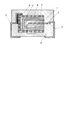
図1は本発明における固体電解コンデンサの断面図であり、図2、図3は図1における破線部分の拡大図である。 FIG. 1 is a cross-sectional view of a solid electrolytic capacitor according to the present invention, and FIGS. 2 and 3 are enlarged views of broken lines in FIG.
図1、図2に示すように、多孔質体の弁作用金属からなる陽極導体1と、その陽極導体1の表面に形成された誘電体層2を有し、その誘電体層2の表面にアミノ基を持つシランカップリング剤層9を形成する。
As shown in FIG. 1 and FIG. 2, an
続いて、ポリアニオンからなる導電性高分子分散液に浸漬し、引き上げた後に乾燥することで固体電解質層10を形成する。
Subsequently, the
固体電解質層10形成後、グラファイト層51と銀層52よりなる陰極層5を形成する。次に、陰極層5とリードフレーム71を導電性接着剤6で接着し、陽極リード3とリードフレーム72を溶接し、リードフレーム71、72を除く素子の露出部をモールド形成することで外装樹脂8を形成し、固体電解コンデンサを得る。
After the formation of the
アミノ基を持つシランカップリング剤層9はアミノ基を持つシランカップリング剤を含む溶液中に浸漬した後、乾燥させる。これにより、誘電体層2の表面にアミノ基を持つシランカップリング剤層9が形成される。シランカップリング剤層9形成に用いられるアミノ基を持つシランカップリング剤としては3−(2−アミノエチルアミノ)プロピルジメトキシメチルシラン,3−(2−アミノエチルアミノ)プロピルトリエトキシシラン,3−(2−アミノエチルアミノ)プロピルトリメトキシシラン,3−アミノプロピルジエトキシメチルシラン,3−アミノプロピルトリエトキシシラン,3−アミノプロピルトリメトキシシランが好ましい。ここで、アミノ基を持つシランカップリング剤を溶解させる溶媒としては水のみでも、水と水に可溶な有機溶媒を含む混和溶媒のどちらでも良い。
The silane
固体電解質層10形成に用いられる導電性高分子分散液は、ピロール、チオフェン、アニリンおよびその誘導体を少なくとも1種以上含む重合体と溶媒を主として構成されている。重合体としては、特にピロール、3,4−エチレンジオキシチオフェン、およびその誘導体を含むことが好ましい。ドーパントとしては、例えばナフタレンスルホン酸、ベンゼンスルホン酸、スチレンスルホン酸およびその誘導体からなるスルホン酸系化合物が好ましい。その中でもポリスチレンスルホン酸が特に好ましい。なお、ドーパントとなるポリアニオンの量はピロール、チオフェン、アニリンおよびその誘導体を少なくとも1種以上含む重合体に対して2倍以上の質量となることで、固体電解質層とシランカップリング剤層の間の密着力を増大させることができるため望ましい。
The conductive polymer dispersion used for forming the
溶媒としては水のみでも、水に可溶な有機溶媒とを含む混和溶媒のどちらでも良い。有機溶媒としては、ジメチルスルホルムアミド、ジメチルアセトアミド、ジメチルスルホキシド、エチレングリコール、グリセリン、ソルビトール等の極性溶媒が好ましい。 As the solvent, either water alone or a mixed solvent containing an organic solvent soluble in water may be used. As the organic solvent, polar solvents such as dimethylsulfuramide, dimethylacetamide, dimethylsulfoxide, ethylene glycol, glycerin and sorbitol are preferable.
尚、図3のように、誘電体層2と前記アミノ基を持つシランカップリング剤層9の間に導電性高分子からなる固体電解質層11が形成されていても良い。固体電解質層11は、化学重合法または電解重合法または導電性高分子分散液を塗布し乾燥する方法のいずれか一種以上の方法で形成されることで、多孔質体の一部を充填する。また、固体電解質層11はピロール、チオフェン、アニリンおよびその誘導体を少なくとも1種含む重合体を含有することが好ましい。加えて、ドーパントとしてはスルホン酸系化合物が好ましい。
As shown in FIG. 3, a
以下、本発明を実施例に基づきさらに具体的に説明するが、本発明はこれらの実施例のみに限定されるものではない。 EXAMPLES Hereinafter, although this invention is demonstrated further more concretely based on an Example, this invention is not limited only to these Examples.
(実施例1)
図2に示す断面構造の固体電解コンデンサを以降の手順で作成した。タンタル粉末を用いた縦3.5mm、横3.0mm、厚さ1.5mmの直方体に陽極リード3としてタンタルワイヤーが埋め込まれたプレス体を焼結し、タンタル焼結体すなわち陽極導体1を作製した。この焼結体をリン酸水溶液中で陽極酸化を行い、誘電体層2を形成した。
Example 1
A solid electrolytic capacitor having a cross-sectional structure shown in FIG. 2 was prepared by the following procedure. A tantalum sintered body, that is, an
次に、3−アミノプロピルトリメトキシシランの5質量%水溶液に誘電体層2で被覆された陽極導体1を浸漬し、120℃、60分乾燥することでアミノ基を持つシランカップリング剤層9を形成した。この時のアミノ基を持つシランカップリング剤層9の厚みは50nmであった。
Next, the
その後、ポリスチレンスルホン酸がポリ3,4−エチレンジオキシチオフェンにドーピングしている導電性高分子を水溶液中に分散させた溶液に浸漬し、一定の速度で引き上げた後に125℃で20分乾燥することで固体電解質層10を形成した。導電性高分子分散液中のポリスチレンスルホン酸の質量はポリ3,4−エチレンジオキシチオフェンに対して3倍である。この時、導電性高分子分散液のゼータ電位は−70mVであった。尚、ゼータ電位は電気泳動光散乱法によって測定を行った。
Thereafter, the conductive polymer doped with poly3,4-ethylenedioxythiophene with polystyrene sulfonic acid is immersed in a solution dispersed in an aqueous solution, pulled up at a constant rate, and then dried at 125 ° C. for 20 minutes. Thus, the
次に、導電性ペーストとしてグラファイトペーストと銀ペーストを使用して陰極層5を形成し、導電性接着剤6や溶接などを用いて陰極層5および陽極リード3それぞれにリードフレーム71、72を接続した後に全体を外装樹脂8でモールド外装し、固体電解コンデンサを得た。
Next, the
(実施例2)
図2に示す断面構造の固体電解コンデンサを以降の手順で作成した。陽極導体1に誘電体層2を実施例1と同様に形成し、次に3−アミノプロピルトリメトキシシランの50質量%水溶液に浸漬し、120℃、60分乾燥することで厚み500nmのシランカップリング剤層9を形成し、実施例1と同様に固体電解質層10を形成した。シランカップリング剤層9の厚みは500nmであった。
(Example 2)
A solid electrolytic capacitor having a cross-sectional structure shown in FIG. 2 was prepared by the following procedure. A
(実施例3)
図2に示す断面構造の固体電解コンデンサを以降の手順で作成した。実施例1の場合と同様に陽極導体1に誘電体層2、シランカップリング剤層9を形成した。次にポリスチレンスルホン酸がポリ3,4−エチレンジオキシチオフェンにドーピングしている導電性高分子を水溶液中に分散させた溶液であり、ポリスチレンスルホン酸の質量はポリ3,4−エチレンジオキシチオフェンと等量である導電性高分子分散液に浸漬し、一定の速度で引き上げた後に125℃で20分乾燥することで固体電解質層10を形成した。導電性高分子分散液のゼータ電位は−30mVであった。
(Example 3)
A solid electrolytic capacitor having a cross-sectional structure shown in FIG. 2 was prepared by the following procedure. In the same manner as in Example 1, a
その後、実施例1と同様に陰極層5を形成し、以降は実施例1と同様に固体電解コンデンサを作製した。
Thereafter, the
(実施例4)
図3に示す断面構造の固体電解コンデンサを以降の手順で作成した。実施例1の場合と同様に陽極導体1に誘電体層2を形成した。次に、酸化剤であるペルオキソ二硫酸アンモニウムを15質量%、1,3,6−ナフタレントリスルホン酸を15質量%含む水溶液に、誘電体層2で被覆された陽極導体1を浸漬し、さらに室温で保持して3,4−エチレンジオキシチオフェンに浸漬し、さらに室温で30分保持して3,4−エチレンジオキシチオフェンの重合を行った。これら一連の重合操作を3回繰り返して、ポリ3,4−エチレンジオキシチオフェンからなる固体電解質層11を形成した。その後、エタノールで未反応有機物の除去を行い、室温で保持して乾燥した。
Example 4
A solid electrolytic capacitor having a cross-sectional structure shown in FIG. 3 was prepared by the following procedure. In the same manner as in Example 1, the
次に、シランカップリング剤層9、固体電解質層10を実施例1と同様に形成し、以降は実施例1と同様に固体電解コンデンサを作製した。
Next, a silane
(比較例1)
実施例1の場合と同様に誘電体層2を形成した。次に、固体電解質層10を実施例1と同様に形成し、以降は実施例1と同様に固体電解コンデンサを作製した。 すなわち、図2に示す断面構造の固体電解コンデンサのシランカップリング剤層9が設けられていない構造となる。
(Comparative Example 1)
A
(比較例2)
実施例1の場合と同様に誘電体層2を形成した。次に、アミノ基を持たないシランカップリング剤プロピルトリメトキシシランの5質量%水溶液に浸漬し、120℃、60分乾燥することでアミノ基を持たないシランカップリング剤層9を形成した。その後、実施例1と同様に、固体電解質層10を形成し、以降は実施例1と同様に固体電解コンデンサを作製した。すなわち、図2に示す断面構造の固体電解コンデンサとなる。
(Comparative Example 2)
A
(比較例3)
実施例3の場合と同様に誘電体層2、固体電解質層11を形成した。次に、アミノ基を持たないシランカップリング剤層9を比較例2と同様に形成した。その後、実施例1と同様に、固体電解質層10を形成し、以降は実施例1と同様に固体電解コンデンサを作製した。すなわち、図3に示す断面構造の固体電解コンデンサとなる。
(Comparative Example 3)
In the same manner as in Example 3, the
実施例1〜4及び比較例1〜3の条件でそれぞれ作製した固体電解コンデンサについて電気特性を測定した。測定項目はESRである。ESRは交流インピーダンスブリッジ法により測定している。ESRは印加した基準信号の周波数が100kHz、電圧が1Vrms、DCバイアスは1.5Vとしている。固体電解コンデンサの特性値を、表1に示す。 Electrical characteristics of the solid electrolytic capacitors produced under the conditions of Examples 1 to 4 and Comparative Examples 1 to 3 were measured. The measurement item is ESR. ESR is measured by the AC impedance bridge method. In the ESR, the frequency of the applied reference signal is 100 kHz, the voltage is 1 Vrms, and the DC bias is 1.5V. Table 1 shows the characteristic values of the solid electrolytic capacitor.

表1において、比較例1の固体電解コンデンサはESRが36mΩであったのに対し、実施例1はESRが30mΩと低くなった。これは第一の固体電解質層の密着性向上によるESRの低減であることが分かる。また、アミノ基を持たないシランカップリング剤層を形成した比較例2のESRが34mΩあったのに対し、本発明の実施例1のESRが30mΩであったため、アミノ基を持ったシランカップリング剤を用いることによって静電的作用が発生し、密着性に優れた固体電解層が形成されることが分かる。 In Table 1, the solid electrolytic capacitor of Comparative Example 1 had an ESR of 36 mΩ, while Example 1 had an ESR as low as 30 mΩ. This shows that the ESR is reduced by improving the adhesion of the first solid electrolyte layer. Further, the ESR of Comparative Example 2 in which a silane coupling agent layer having no amino group was 34 mΩ, whereas the ESR of Example 1 of the present invention was 30 mΩ, so that the silane coupling having an amino group was performed. It can be seen that by using the agent, an electrostatic action is generated and a solid electrolytic layer having excellent adhesion is formed.
次に、アミノ基を持つシランカップリング剤層の厚みが500nmの実施例2の固体電解コンデンサはESRが35mΩであった。この値はESRとしては高く、アミノ基を持つシランカップリング剤層が厚すぎたものと考えられる。 Next, the solid electrolytic capacitor of Example 2 in which the thickness of the silane coupling agent layer having an amino group was 500 nm had an ESR of 35 mΩ. This value is high as ESR, and it is considered that the silane coupling agent layer having an amino group was too thick.
また、ポリスチレンスルホン酸の質量がポリ3,4−エチレンジオキシチオフェンと等量の導電性高分子分散液を用いた実施例3は、アミノ基を持たないシランカップリング剤層を形成した比較例2よりも低くなったものの、ポリスチレンスルホン酸の質量がポリ3,4−エチレンジオキシチオフェンに対して3倍である導電性高分子分散液を用いた実施例1よりESRが高くなった。これより、ポリスチレンスルホン酸の質量がポリ3,4−エチレンジオキシチオフェンに対して2倍以上の導電性高分子分散液でより大きな静電的作用が発生し、密着性に優れた第一の固体電解層が形成されることが分かる。 Further, Example 3 using a conductive polymer dispersion in which the mass of polystyrene sulfonic acid is equal to that of poly3,4-ethylenedioxythiophene is a comparative example in which a silane coupling agent layer having no amino group is formed. Although lower than 2, the ESR was higher than that in Example 1 using the conductive polymer dispersion in which the mass of polystyrene sulfonic acid was 3 times that of poly3,4-ethylenedioxythiophene. As a result, a larger electrostatic action is generated in the conductive polymer dispersion having a polystyrene sulfonic acid mass twice or more that of poly3,4-ethylenedioxythiophene, and the first excellent in adhesion. It can be seen that a solid electrolytic layer is formed.
また、実施例4及び比較例3について、アミノ基を持つシランカップリング剤層を形成した実施例4はアミノ基を持たないシランカップリング剤層を形成した比較例3に比べ低いESRを示した。従って、固体電解質層11を誘電体層2とシランカップリング剤層9の間に設けると、ESRをより減少させることができることが分かる。
Moreover, about Example 4 and Comparative Example 3, Example 4 which formed the silane coupling agent layer which has an amino group showed low ESR compared with Comparative Example 3 which formed the silane coupling agent layer which does not have an amino group. . Therefore, it can be seen that ESR can be further reduced by providing the
1 陽極導体
2 誘電体層
3 陽極リード
4、10、11 固体電解質層
5 陰極層
51 グラファイト層
52 銀層
6 導電性接着剤
8 外装樹脂
9 シランカップリング剤層
71、72 リードフレーム
DESCRIPTION OF
Claims (9)
Priority Applications (1)
| Application Number | Priority Date | Filing Date | Title |
|---|---|---|---|
| JP2011036581A JP2012174948A (en) | 2011-02-23 | 2011-02-23 | Solid electrolytic capacitor and method for manufacturing the same |
Applications Claiming Priority (1)
| Application Number | Priority Date | Filing Date | Title |
|---|---|---|---|
| JP2011036581A JP2012174948A (en) | 2011-02-23 | 2011-02-23 | Solid electrolytic capacitor and method for manufacturing the same |
Publications (2)
| Publication Number | Publication Date |
|---|---|
| JP2012174948A true JP2012174948A (en) | 2012-09-10 |
| JP2012174948A5 JP2012174948A5 (en) | 2013-11-14 |
Family
ID=46977553
Family Applications (1)
| Application Number | Title | Priority Date | Filing Date |
|---|---|---|---|
| JP2011036581A Pending JP2012174948A (en) | 2011-02-23 | 2011-02-23 | Solid electrolytic capacitor and method for manufacturing the same |
Country Status (1)
| Country | Link |
|---|---|
| JP (1) | JP2012174948A (en) |
Cited By (22)
| Publication number | Priority date | Publication date | Assignee | Title |
|---|---|---|---|---|
| JP2014148631A (en) * | 2013-02-04 | 2014-08-21 | Nec Tokin Corp | Conductive polymer solution and method for producing the same, conductive polymer, and solid electrolytic capacitor |
| KR20150039580A (en) * | 2013-10-02 | 2015-04-10 | 에이브이엑스 코포레이션 | Solid electrolytic capacitor for use under high temperature and humidity conditions |
| WO2017022204A1 (en) * | 2015-07-31 | 2017-02-09 | パナソニックIpマネジメント株式会社 | Electrolytic capacitor and method for producing same |
| WO2017127267A1 (en) | 2016-01-18 | 2017-07-27 | Avx Corporation | Solid electroltyic capacitor with improved leakage current |
| WO2018053060A1 (en) * | 2016-09-15 | 2018-03-22 | Avx Corporation | Solid electrolytic capacitor with improved leakage current |
| WO2018075329A1 (en) * | 2016-10-18 | 2018-04-26 | Avx Corporation | Solid electrolytic capacitor with improved performance at high temperatures and voltages |
| WO2018089960A1 (en) * | 2016-11-14 | 2018-05-17 | Avx Corporation | Medical device containing a solid electrolytic capacitor |
| KR20190058539A (en) * | 2016-10-18 | 2019-05-29 | 에이브이엑스 코포레이션 | Solid electrolyte capacitor assembly |
| US10622160B2 (en) | 2017-03-06 | 2020-04-14 | Avx Corporation | Solid electrolytic capacitor assembly |
| US10679795B2 (en) | 2015-06-30 | 2020-06-09 | Panasonic Intellectual Property Management Co., Ltd. | Electrolytic capacitor and method for manufacturing same |
| US10741333B2 (en) | 2016-10-18 | 2020-08-11 | Avx Corporation | Solid electrolytic capacitor with improved leakage current |
| US10770238B2 (en) | 2017-07-03 | 2020-09-08 | Avx Corporation | Solid electrolytic capacitor assembly with hydrophobic coatings |
| WO2021119088A1 (en) * | 2019-12-10 | 2021-06-17 | Avx Corporation | Tantalum capacitor with increased stability |
| WO2021119065A1 (en) * | 2019-12-10 | 2021-06-17 | Avx Corporation | Solid electrolytic capacitor containing a pre-coat and intrinsically conductive polymer |
| US11114250B2 (en) | 2018-08-10 | 2021-09-07 | Avx Corporation | Solid electrolytic capacitor formed from conductive polymer particles |
| US11183342B2 (en) | 2018-08-10 | 2021-11-23 | Avx Corporation | Solid electrolytic capacitor containing polyaniline |
| US11257628B2 (en) | 2017-07-03 | 2022-02-22 | KYOCERA AVX Components Corporation | Solid electrolytic capacitor containing a nanocoating |
| US11462366B2 (en) | 2018-08-10 | 2022-10-04 | KYOCERA AVX Components Corporation | Solid electrolytic capacitor containing an intrinsically conductive polymer |
| US11631548B2 (en) | 2020-06-08 | 2023-04-18 | KYOCERA AVX Components Corporation | Solid electrolytic capacitor containing a moisture barrier |
| US11670461B2 (en) | 2019-09-18 | 2023-06-06 | KYOCERA AVX Components Corporation | Solid electrolytic capacitor for use at high voltages |
| US11837415B2 (en) | 2021-01-15 | 2023-12-05 | KYOCERA AVX Components Corpration | Solid electrolytic capacitor |
| US11955294B2 (en) | 2018-12-11 | 2024-04-09 | KYOCERA AVX Components Corporation | Solid electrolytic capacitor containing an intrinsically conductive polymer |
Citations (3)
| Publication number | Priority date | Publication date | Assignee | Title |
|---|---|---|---|---|
| JP2006140443A (en) * | 2004-10-15 | 2006-06-01 | Sanyo Electric Co Ltd | Solid electrolytic capacitor and method of manufacturing the same |
| JP2009009999A (en) * | 2007-06-26 | 2009-01-15 | Shin Etsu Polymer Co Ltd | Capacitor and manufacturing method thereof |
| JP2010103489A (en) * | 2008-09-29 | 2010-05-06 | Sanyo Electric Co Ltd | Solid electrolytic capacitor |
-
2011
- 2011-02-23 JP JP2011036581A patent/JP2012174948A/en active Pending
Patent Citations (3)
| Publication number | Priority date | Publication date | Assignee | Title |
|---|---|---|---|---|
| JP2006140443A (en) * | 2004-10-15 | 2006-06-01 | Sanyo Electric Co Ltd | Solid electrolytic capacitor and method of manufacturing the same |
| JP2009009999A (en) * | 2007-06-26 | 2009-01-15 | Shin Etsu Polymer Co Ltd | Capacitor and manufacturing method thereof |
| JP2010103489A (en) * | 2008-09-29 | 2010-05-06 | Sanyo Electric Co Ltd | Solid electrolytic capacitor |
Cited By (52)
| Publication number | Priority date | Publication date | Assignee | Title |
|---|---|---|---|---|
| JP2014148631A (en) * | 2013-02-04 | 2014-08-21 | Nec Tokin Corp | Conductive polymer solution and method for producing the same, conductive polymer, and solid electrolytic capacitor |
| KR20150039580A (en) * | 2013-10-02 | 2015-04-10 | 에이브이엑스 코포레이션 | Solid electrolytic capacitor for use under high temperature and humidity conditions |
| JP2015073097A (en) * | 2013-10-02 | 2015-04-16 | エイヴィーエックス コーポレイション | Solid electrolytic capacitor for use under high temperature and high humidity condition |
| CN110459406A (en) * | 2013-10-02 | 2019-11-15 | Avx公司 | For the solid electrolytic capacitor under the conditions of high-temperature high-humidity |
| KR102244980B1 (en) * | 2013-10-02 | 2021-04-27 | 에이브이엑스 코포레이션 | Solid electrolytic capacitor for use under high temperature and humidity conditions |
| US10679795B2 (en) | 2015-06-30 | 2020-06-09 | Panasonic Intellectual Property Management Co., Ltd. | Electrolytic capacitor and method for manufacturing same |
| CN107851517A (en) * | 2015-07-31 | 2018-03-27 | 松下知识产权经营株式会社 | Electrolytic capacitor and its manufacture method |
| JP2022002340A (en) * | 2015-07-31 | 2022-01-06 | パナソニックIpマネジメント株式会社 | Electrolytic capacitor and method for manufacturing the same |
| JP7203309B2 (en) | 2015-07-31 | 2023-01-13 | パナソニックIpマネジメント株式会社 | Electrolytic capacitor and manufacturing method thereof |
| JPWO2017022204A1 (en) * | 2015-07-31 | 2018-05-24 | パナソニックIpマネジメント株式会社 | Electrolytic capacitor and manufacturing method thereof |
| CN107851517B (en) * | 2015-07-31 | 2020-05-19 | 松下知识产权经营株式会社 | Electrolytic capacitor and method for manufacturing the same |
| WO2017022204A1 (en) * | 2015-07-31 | 2017-02-09 | パナソニックIpマネジメント株式会社 | Electrolytic capacitor and method for producing same |
| US10475590B2 (en) | 2015-07-31 | 2019-11-12 | Panasonic Intellectual Property Management Co., Ltd. | Electrolytic capacitor and method for producing same |
| EP3405965A4 (en) * | 2016-01-18 | 2019-09-25 | AVX Corporation | Solid electrolytic capacitor with improved leakage current |
| JP2019505993A (en) * | 2016-01-18 | 2019-02-28 | エイブイエックス コーポレイション | Solid electrolytic capacitor with improved leakage current |
| US10186382B2 (en) | 2016-01-18 | 2019-01-22 | Avx Corporation | Solid electrolytic capacitor with improved leakage current |
| IL260177A (en) * | 2016-01-18 | 2018-07-31 | Avx Corp | Solid electrolytic capacitor with improved leakage current |
| JP7398867B2 (en) | 2016-01-18 | 2023-12-15 | キョーセラ・エイブイエックス・コンポーネンツ・コーポレーション | Solid electrolytic capacitor with improved leakage current |
| WO2017127267A1 (en) | 2016-01-18 | 2017-07-27 | Avx Corporation | Solid electroltyic capacitor with improved leakage current |
| US11056286B2 (en) | 2016-09-15 | 2021-07-06 | Avx Corporation | Solid electrolytic capacitor with improved leakage current |
| US10763046B2 (en) | 2016-09-15 | 2020-09-01 | Avx Corporation | Solid electrolytic capacitor with improved leakage current |
| WO2018053060A1 (en) * | 2016-09-15 | 2018-03-22 | Avx Corporation | Solid electrolytic capacitor with improved leakage current |
| US10892095B2 (en) | 2016-10-18 | 2021-01-12 | Avx Corporation | Solid electrolytic capacitor assembly |
| KR102397418B1 (en) * | 2016-10-18 | 2022-05-12 | 교세라 에이브이엑스 컴포넌츠 코포레이션 | Solid Electrolytic Capacitor Assemblies |
| WO2018075329A1 (en) * | 2016-10-18 | 2018-04-26 | Avx Corporation | Solid electrolytic capacitor with improved performance at high temperatures and voltages |
| KR102449758B1 (en) | 2016-10-18 | 2022-09-30 | 교세라 에이브이엑스 컴포넌츠 코포레이션 | Solid electrolytic capacitor with improved performance at high temperatures and voltages |
| KR20220109477A (en) * | 2016-10-18 | 2022-08-04 | 교세라 에이브이엑스 컴포넌츠 코포레이션 | Solid electrolytic capacitor with improved performance at high temperatures and voltages |
| JP2019537281A (en) * | 2016-10-18 | 2019-12-19 | エイブイエックス コーポレイション | Solid electrolytic capacitors with improved performance at high temperatures and voltages |
| US11387047B2 (en) | 2016-10-18 | 2022-07-12 | KYOCERA AVX Components Corporation | Solid electrolytic capacitor with improved performance at high temperatures and voltages |
| US10741333B2 (en) | 2016-10-18 | 2020-08-11 | Avx Corporation | Solid electrolytic capacitor with improved leakage current |
| CN109891536A (en) * | 2016-10-18 | 2019-06-14 | 阿维科斯公司 | The solid electrolytic capacitor being had improved properties under high-temperature and voltage |
| JP7055140B2 (en) | 2016-10-18 | 2022-04-15 | キョーセラ・エイブイエックス・コンポーネンツ・コーポレーション | Solid electrolytic capacitors with improved performance at high temperatures and voltages |
| US11170942B2 (en) | 2016-10-18 | 2021-11-09 | Avx Corporation | Solid electrolytic capacitor with improved leakage current |
| KR20190058539A (en) * | 2016-10-18 | 2019-05-29 | 에이브이엑스 코포레이션 | Solid electrolyte capacitor assembly |
| WO2018089960A1 (en) * | 2016-11-14 | 2018-05-17 | Avx Corporation | Medical device containing a solid electrolytic capacitor |
| US10737101B2 (en) | 2016-11-14 | 2020-08-11 | Avx Corporation | Medical device containing a solid electrolytic capacitor |
| US10622160B2 (en) | 2017-03-06 | 2020-04-14 | Avx Corporation | Solid electrolytic capacitor assembly |
| US11257628B2 (en) | 2017-07-03 | 2022-02-22 | KYOCERA AVX Components Corporation | Solid electrolytic capacitor containing a nanocoating |
| US10770238B2 (en) | 2017-07-03 | 2020-09-08 | Avx Corporation | Solid electrolytic capacitor assembly with hydrophobic coatings |
| US11791106B2 (en) | 2018-08-10 | 2023-10-17 | KYOCERA AVX Components Corporation | Solid electrolytic capacitor containing polyaniline |
| US11114250B2 (en) | 2018-08-10 | 2021-09-07 | Avx Corporation | Solid electrolytic capacitor formed from conductive polymer particles |
| US11183342B2 (en) | 2018-08-10 | 2021-11-23 | Avx Corporation | Solid electrolytic capacitor containing polyaniline |
| US11462366B2 (en) | 2018-08-10 | 2022-10-04 | KYOCERA AVX Components Corporation | Solid electrolytic capacitor containing an intrinsically conductive polymer |
| US11756746B2 (en) | 2018-08-10 | 2023-09-12 | KYOCERA AVX Components Corporation | Solid electrolytic capacitor containing an intrinsically conductive polymer |
| US11955294B2 (en) | 2018-12-11 | 2024-04-09 | KYOCERA AVX Components Corporation | Solid electrolytic capacitor containing an intrinsically conductive polymer |
| US11670461B2 (en) | 2019-09-18 | 2023-06-06 | KYOCERA AVX Components Corporation | Solid electrolytic capacitor for use at high voltages |
| WO2021119088A1 (en) * | 2019-12-10 | 2021-06-17 | Avx Corporation | Tantalum capacitor with increased stability |
| US11776759B2 (en) | 2019-12-10 | 2023-10-03 | KYOCER AVX Components Corporation | Tantalum capacitor with increased stability |
| US11823846B2 (en) | 2019-12-10 | 2023-11-21 | KYOCERA AVX Components Corporation | Solid electrolytic capacitor containing a pre-coat and intrinsically conductive polymer |
| WO2021119065A1 (en) * | 2019-12-10 | 2021-06-17 | Avx Corporation | Solid electrolytic capacitor containing a pre-coat and intrinsically conductive polymer |
| US11631548B2 (en) | 2020-06-08 | 2023-04-18 | KYOCERA AVX Components Corporation | Solid electrolytic capacitor containing a moisture barrier |
| US11837415B2 (en) | 2021-01-15 | 2023-12-05 | KYOCERA AVX Components Corpration | Solid electrolytic capacitor |
Similar Documents
| Publication | Publication Date | Title |
|---|---|---|
| JP2012174948A (en) | Solid electrolytic capacitor and method for manufacturing the same | |
| JP6790156B2 (en) | A dispersion containing a mixture of a conductive polymer having a chain-bound counterion for use in a capacitor anode and a conductive polymer having a non-chain-bonded counterion. | |
| TWI478189B (en) | Solid electrolytic capacitor and method of manufacturing thereof | |
| US8724296B2 (en) | Solid electrolytic capacitor and fabrication method thereof | |
| US8083920B2 (en) | Method for manufacturing solid electrolytic capacitor | |
| US8206467B2 (en) | Method for manufacturing a solid electrolytic capacitor | |
| JP4787967B2 (en) | Electrolytic capacitor element and manufacturing method thereof | |
| JP2012043958A (en) | Solid electrolytic capacitor and manufacturing method thereof | |
| US7940515B2 (en) | Solid electrolytic capacitor | |
| JP2011181611A (en) | Solid electrolytic capacitor and manufacturing method of the same | |
| JP5543001B2 (en) | Electrolytic capacitor manufacturing method | |
| JP2013074032A (en) | Method for manufacturing solid electrolytic capacitor | |
| KR102104424B1 (en) | Method for manufacturing solid electrolytic capacitor, and solid electrolytic capacitor | |
| JP5895136B2 (en) | Electrolytic capacitor manufacturing method | |
| JP2012244077A (en) | Method for manufacturing solid electrolytic capacitor | |
| JP2014027040A (en) | Conductive polymer dispersion liquid for manufacturing solid electrolytic capacitor and solid electrolytic capacitor manufactured using the same | |
| US9048024B2 (en) | Solid electrolytic capacitor and method for producing the same | |
| JPWO2015198547A1 (en) | Electrolytic capacitor manufacturing method | |
| JP2014011222A (en) | Conductive polymer dispersion for manufacturing solid electrolytic capacitor and solid electrolytic capacitor manufactured by using the same | |
| US8513123B2 (en) | Method of manufacturing solid electrolytic capacitor | |
| US9818550B2 (en) | Solid electrolytic capacitor manufacturing method and solid electrolytic capacitor | |
| JPWO2015198546A1 (en) | Electrolytic capacitor manufacturing method | |
| JP2017222795A (en) | Conductive polymer dispersion liquid and method for producing solid electrolytic capacitor using the same | |
| JP5965100B2 (en) | Solid electrolytic capacitor and manufacturing method thereof | |
| JP4891140B2 (en) | Manufacturing method of solid electrolytic capacitor |
Legal Events
| Date | Code | Title | Description |
|---|---|---|---|
| A521 | Written amendment |
Free format text: JAPANESE INTERMEDIATE CODE: A523 Effective date: 20131001 |
|
| A621 | Written request for application examination |
Free format text: JAPANESE INTERMEDIATE CODE: A621 Effective date: 20131106 |
|
| A977 | Report on retrieval |
Free format text: JAPANESE INTERMEDIATE CODE: A971007 Effective date: 20140627 |
|
| A131 | Notification of reasons for refusal |
Free format text: JAPANESE INTERMEDIATE CODE: A131 Effective date: 20140709 |
|
| A02 | Decision of refusal |
Free format text: JAPANESE INTERMEDIATE CODE: A02 Effective date: 20150225 |