JP2012172910A - System for operating indoor environmental control device - Google Patents
System for operating indoor environmental control device Download PDFInfo
- Publication number
- JP2012172910A JP2012172910A JP2011035368A JP2011035368A JP2012172910A JP 2012172910 A JP2012172910 A JP 2012172910A JP 2011035368 A JP2011035368 A JP 2011035368A JP 2011035368 A JP2011035368 A JP 2011035368A JP 2012172910 A JP2012172910 A JP 2012172910A
- Authority
- JP
- Japan
- Prior art keywords
- indoor environment
- annotation
- display
- devices
- control unit
- Prior art date
- Legal status (The legal status is an assumption and is not a legal conclusion. Google has not performed a legal analysis and makes no representation as to the accuracy of the status listed.)
- Withdrawn
Links
Images


Landscapes
- Air Conditioning Control Device (AREA)
Abstract
Description
本発明は、空調機器、暖房機器、加湿器、照明器具といった室内環境調整用機器の操作システムに関するものである。 The present invention relates to an operation system for an indoor environment adjusting device such as an air conditioner, a heater, a humidifier, and a lighting fixture.
室内環境は、空調機器、暖房機器、加湿器、照明器具といった複数の機器で調整されるが、これらの各機器のリモート制御を個別に行う場合、各機器毎にリモートコントローラが必要となり、その操作もきわめて煩わしいことになる。 The indoor environment is adjusted by multiple devices such as air conditioners, heating devices, humidifiers, and lighting fixtures. When remote control of these devices is performed individually, a remote controller is required for each device. Will be very annoying.
このために特開2007−192472号公報(特許文献1)において、複数の機器を単一の制御手段の制御下におき、単一の制御手段に対する操作だけで複数の機器を制御できるようにしたものが提案されている。しかし、制御する機器が増えたり、同種の機器が複数存在する場合、操作対象となる機器を特定することが困難となる。 For this reason, in Japanese Patent Application Laid-Open No. 2007-192472 (Patent Document 1), a plurality of devices are placed under the control of a single control means, and a plurality of devices can be controlled only by an operation on the single control means. Things have been proposed. However, when the number of devices to be controlled increases or there are a plurality of devices of the same type, it is difficult to specify the device to be operated.
特開2000−253123号公報には、多機能携帯電話を複数の機器のリモートコントローラとして利用する案が示されているが、このものにおいても、制御する機器が増えたり、同種の機器が複数存在すると、操作対象となる機器を特定することが困難となる。 Japanese Patent Laid-Open No. 2000-253123 discloses a plan to use a multi-function mobile phone as a remote controller for a plurality of devices. However, even in this case, the number of devices to be controlled increases or there are a plurality of similar devices. Then, it becomes difficult to specify a device to be operated.
本発明はこのような点に鑑みなされたものであって、室内環境調整用機器が複数あっても各機器を的確に制御することができる室内環境調整用機器の操作システムを提供することを課題とするものである。 This invention is made in view of such a point, Comprising: Even if there exist multiple equipment for indoor environment adjustment, it is a subject to provide the operation system of the equipment for indoor environment adjustment which can control each apparatus exactly It is what.
本発明は、室内環境調整用の機器に対する操作手段であって、上記機器との間で通信を行う通信手段と室内撮影のためのカメラとカメラで映した画像を表示するディスプレーとを備えている携帯機器と、上記ディスプレーに表示された画像中に映っている機器の像を上記機器に対応付ける特定手段とを有しており、上記携帯機器は、上記ディスプレーに表示された画像中に映っている機器の像に、上記特定手段で特定された機器に関する操作画面をアノテーションとして重ね合わせて表示するものであり、且つ、上記アノテーションに対して加えられた操作の情報を上記特定された機器に対して送信するものであることに特徴を有している。 The present invention is an operation means for a device for adjusting the indoor environment, and includes communication means for communicating with the device, a camera for indoor shooting, and a display for displaying an image projected by the camera. It has a portable device and a specific means for associating the device image shown in the image displayed on the display with the device, and the portable device appears in the image displayed on the display. An operation screen related to the device specified by the specifying means is superimposed on the image of the device and displayed as an annotation, and operation information added to the annotation is displayed for the specified device. It is characterized by being transmitted.
室内環境情報を検知する室内環境センサを備えており、上記携帯機器は室内環境センサから得られる室内環境情報をアノテーションとしてディスプレーに上記操作画面アノテーションと共に表示するものとしてもよく、更には複数の室内環境調整用の機器を集中制御する制御ユニットを備えており、携帯機器は該制御ユニットを通じて各室内環境調整用の機器に対する操作を行うものであってもよい。 An indoor environment sensor for detecting indoor environment information may be provided, and the portable device may display the indoor environment information obtained from the indoor environment sensor as an annotation on the display together with the operation screen annotation. A control unit that centrally controls the devices for adjustment may be provided, and the portable device may operate each indoor environment adjustment device through the control unit.
本発明においては、室内に同一手段の機器が複数ある場合でも、機器とその操作の対応関係がディスプレーの画面上で明確になるために、その直感性によってユーザーの操作性を向上させることができる。 In the present invention, even when there are a plurality of devices of the same means in the room, the correspondence between the devices and their operations is clarified on the display screen, so that the user's operability can be improved by the intuition. .
以下、本発明を実施の形態の一例について説明すると、図3は本発明に係る操作システムの全体を示しており、図中の11〜15はいずれも室内環境調整用機器であって、ここではサーキュレーションファン11、床暖房機器12、エアコン(空調機器)13、照明器具14,15を例として示している。また、ここにおけるサーキュレーションファン11には室外(屋外)温度センサ21、天井近傍温度センサ22、床面近傍温度センサ23、壁面温度センサ24、湿度センサ25が室内環境用センサとして接続されており、床暖房機器12には床温度センサ26が室内環境用センサとして接続されている。
Hereinafter, an example of an embodiment of the present invention will be described. FIG. 3 shows the entire operation system according to the present invention, and 11 to 15 in the figure are all indoor environment adjusting devices. A
そして本例においては、上記の室内環境調整用機器11〜15は、連繋制御ユニット3に接続されて、連繋制御ユニット3側からの制御で各室内環境調整用機器11〜15の動作を制御することができるものとなっている。また連繋制御ユニット3は、後述する携帯機器1にAR(Augmented Reality,拡張現実感)を提供するために、接続されている各室内環境調整用機器11〜15の動作状態や操作に関するアノテーション(エアタグとも称される)4の生成用データを有するとともに、携帯機器1との間の通信のための通信手段33を備えている。
And in this example, said indoor environment adjustment apparatus 11-15 is connected to the
図中31は連繋制御ユニット3が備える操作コントローラであり、該操作コントローラ31を操作することで、各室内環境調整用機器11〜15を個別に操作することができる。なお、ここにおける連繋制御ユニット3は、例えば室内暖房に際して、エアコン13と床暖房機器12とを室内環境に応じて連繋させた状態で制御する機能や、人体センサ35による人の有無の検知出力に応じて機器11〜15の動作を制御する機能なども備えているが、この点についての説明は省略する。操作コントローラ31に室温・湿度センサ等の室内環境用センサ32を設けておくようにしてもよい。
In the figure,
そして、本操作システムにおいては、上記連繋制御ユニット3と通信手段を介して接続される携帯機器1を備えている。この携帯機器1は、少なくともカメラとタッチパネル型のディスプレー10とを備えるとともに、上記連繋制御ユニット3との間で通信を行うための通信手段を備えたもので、これらカメラやディスプレーや通信手段を制御する携帯機器1中の演算手段は、カメラで撮影している画像を上記ディスプレー10に表示するとともに上記連繋制御ユニット3から送られてくるアノテーション生成用データを基に作成したアノテーション4を上記画像に重ね合わせて表示することができるものとなっている。
And in this operation system, the
上記通信手段としては、Bluetooth(登録商標)等の公知の双方向無線通信手段を好適に用いることができるが、有線通信手段を用いてもよい。また、携帯機器1としては、多機能携帯電話を好適に用いることができる。
As the communication means, known bidirectional wireless communication means such as Bluetooth (registered trademark) can be suitably used, but wired communication means may be used. In addition, as the
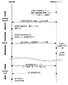
次に動作に基づいて本発明の操作システムにおける操作について説明する。図1及び図2は携帯機器1と連繋制御ユニット3との間の通信についてのフローであって、図1は初期設定時のフローを、図2は通常使用時のフローを示している。
Next, an operation in the operation system of the present invention will be described based on the operation. FIGS. 1 and 2 are flows for communication between the
まず初期設定について説明すると、携帯機器1と連繋制御ユニット3との間での通信を確保した状態において、携帯機器1のカメラで室内の様子をカメラで映して、ディスプレー10に表示された画像中で制御したい機器11〜15、例えばエアコン13が映っている箇所をポイントする。
First, the initial setting will be described. In a state in which communication between the
このポイント操作により、携帯機器1における演算手段は、連繋制御ユニット3に対して連繋制御ユニット3が認識している室内環境調整用機器11〜15の機器リストを要求する。この要求を受けて連繋制御ユニット3は携帯機器1に対して機器リストを送信する。機器リストを受信した携帯機器1において、操作者が機器リストが表示される機器選択画面を選択し、さらにさきほどポイントしたものがエアコン13であることを指定すれば、さきほどポイントした位置にある機器がエアコン13であることを認識するとともに、該エアコン13を選択したこと及びエアコン13についての操作用画面生成用データの送信要求を連繋制御ユニット3側に送る。これを受けて連繋制御ユニット3はエアコン13についての操作用画面生成用データを携帯機器1に送るものであり、このデータを受けた携帯型ユニット1における演算手段は、選択した機器であるエアコン13の操作画面(アノテーション4)を生成して、ディスプレー10上のさきほどポイントした位置と関連付けて表示する。この状態を図4に示す。
By this point operation, the calculation means in the
なお、操作用画面生成用データとは、図4に示しているようなアノテーション4を生成するのに必要なデータであり、たとえば動作モードの種類(冷房、暖房)、各モードで操作するレベル範囲(暖房は18℃〜30℃等)、必要な場合はグラフィックデータである。
Note that the operation screen generation data is data necessary to generate the
上記操作を室内にある機器分だけ繰り返すことで、ディスプレー10に映っている各機器の特定を行う。なお、この一連の操作を一度行えば、画像認識処理と組み合わせることで、画面上に映っているものと機器11〜15との関連付けがなされて次回以降の初期設定を省略することができるようにしておくことが望ましい。
By repeating the above operation for the devices in the room, each device shown on the
機器11〜15が映っている画像を携帯機器1内に保存するとともに、この保存画像に対する機器11〜15との関連付け情報も携帯機器1内に保存し、機器操作に際して上記保存画像を呼び出せば、機器11〜15との関連付け情報も読み込まれ、連繋制御ユニット3との通信で機器情報を受けてディスプレー10に表示している画像中の対応する箇所に対応する機器のアノテーション4を表示できるようにしてもよい。上記初期設定操作そのものも保存画像に対する操作で行うようにしてもよい。
When the images showing the
次に図2に基づいて通常時の操作フローについて説明すると、前述の各機器の特定がなされているとともに、機器11〜15が運転されている時、連繋制御ユニット3は運転されている機器の運転状況概要表示画面の生成用データを携帯機器1に送信する。これを受けて携帯機器1ではディスプレー10上の画像に上記生成用データを基に作成したアノテーション4,4を図5に示すように各機器毎に対応付けて表示する。この時、室内環境センサから得られたデータを基に平均室温等の環境情報についてのアノテーション44も画面に表示することが好ましい。操作や運転状態のアノテーション4と環境情報についてのアノテーション44とを実際の視覚画面上で同時に表示することで、状況に応じた操作がより容易に且つ直感的に行うことができるものとなる。また、この点からも、室内に複数の機器がある場合、これら機器が全て映っている画像を用いることが好ましい。
Next, the normal operation flow will be described with reference to FIG. 2. When each of the above-described devices is specified, and when the
上記のアノテーション4,44が表示されている状態で例えば床暖房機器12の運転設定を変更したい場合には、画面上の床暖房機器12についてのアノテーション4をポイントすることで床暖房機器12を選択すれば、携帯機器1の演算手段は画面上に床暖房機器12の操作画面であるアノテーション4を図6に示すように表示する。そしてアノテーション4として表示された操作画面上で温度設定の変更指示をポイント等のタッチ操作によって行えば、携帯機器1の演算手段は対応する床暖房操作コマンドを連繋制御ユニット3に送信し、連繋制御ユニット3は受けたコマンドに応じた制御信号を床暖房機器12に送る。
For example, when it is desired to change the operation setting of the
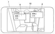
画面上において画像中に映っている機器と対応付けられているアノテーション4に対して操作を加えることで該当する機器の操作を行うことができるものであり、このために図7に示すように、同種の機器が複数(図示例では照明器具が2つ)ある場合でも、画像中で指定した照明器具に対する操作が該当照明器具に対してなされることになるために、取り違えたりすることなく操作を行うことができる。
By operating the
さらには、図5に示す画面がディスプレー10に表示されている状態において、環境情報についてのアノテーション44は、一定間隔(たとえば5分)で携帯機器1から送信される室内環境送信リクエストに応じて連繋制御ユニット3から携帯機器1に送られる室内環境状態送信により、漸次更新されるようにしておく。アノテーション44は、単に温度や湿度を表示するだけでなく、温湿度や風速などの諸要因から求められる室内トータルの快適度指標、例えばPMV、ET、SET等の指標も表示するものであることが好ましい。照明についても感性的な温熱感に寄与するために、照明情報についても触れるものであってもよい。
Furthermore, in the state where the screen shown in FIG. 5 is displayed on the
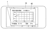
また、ディスプレー10に表示されている環境情報についてのアノテーション44をポイントすれば、図8に示すように、環境情報の詳細が画面上にアノテーション45として、或いは別画面として表示されるようにしておくことが好ましく、この環境情報詳細については、過去の状況も判る形態の表示がなされるものが好ましい。
If the
画像上のどこにどの機器があるのかの機器特定を上記実施例では初期設定時に操作者が手動選択で行うものを示したが、携帯機器1内に各機器11〜15についての形状データを登録しておき、該形状データを利用した画像認識処理によって各機器11〜15を画像中から特定するようにしてもよい。また、対象となる室内環境調整用機器11〜15の特定のための画像認識処理を連繋制御ユニット3側で行うようにしてもよい。この場合、カメラで撮影した画像は通信手段を介して連繋制御ユニット3側にも送って処理を行わせることになる。
In the above embodiment, the device is manually selected at the time of initial setting in order to identify the device where the device is on the image. However, the shape data for each
機器形状による画像認識で機器を特定するのではなく、各機器毎に異なる光学的マーカーを付しておき、該マーカーを画像認識することで機器が特定されるものとしてもよく、さらには携帯機器1に備えたコンパスや傾斜センサ等と、連繋制御ユニット3側に予め記憶させた各機器の位置情報とを用いて機器を特定するものであってもよい。そしてこれらを組み合わせて機器の特定を行うようにしてもよく、このために機器の特定をどのように行うかに関して何ら限定するものではない。
Instead of specifying a device by image recognition based on the device shape, a different optical marker may be attached to each device, and the device may be specified by image recognition of the marker, and further, a portable device. 1 may be used to specify a device using the compass, the tilt sensor, and the like included in 1 and the position information of each device stored in advance on the
このほか、携帯機器1は連繋制御ユニット3を通じて各機器11〜15の制御を行うことになるものを示したが、携帯機器1が各機器11〜15と直接通信を行うことで、各機器11〜15の状態を認識したり各機器11〜15の動作を制御したりするものであってもよい。もっとも、各機器の状態や室内温度環境等を携帯機器1で取得する場合、各機器11〜15やセンサから個別に取得すると、通信対象となる機器11〜15やセンサが増えて通信トラフィックの増大が発生するために、センシング情報を一元管理する機器(本例における連繋制御ユニット3)と通信を行うことで各センシングデータを一度に取得した方がより効率的である。
In addition, although the
また、携帯機器1として指先でポイント操作等を行うことができるタッチパネル型のディスプレー10を備えたものを示したが、画面上に表示されるマウスカーソルを利用してポイント操作等を行うものであってもよい。
Moreover, although the thing provided with the
1 携帯機器
3 連繋制御ユニット
4 アノテーション
10 ディスプレー
11〜15 室内環境調整用機器
21〜26 室内環境用センサ
DESCRIPTION OF
Claims (3)
上記携帯機器は、上記ディスプレーに表示された画像中に映っている機器の像に、上記特定手段で特定された機器に関する操作画面をアノテーションとして重ね合わせて表示するものであり、且つ、上記アノテーションに対して加えられた操作の情報を上記特定された機器に対して送信するものであることを特徴とする室内環境調整用機器の操作システム。 A portable device comprising a communication means for communicating with the device for indoor environment adjustment, a communication means for communicating with the device, a camera for indoor shooting, and a display for displaying an image projected by the camera; Specific means for associating the image of the device shown in the image displayed on the display with the device,
The portable device displays an operation screen related to the device specified by the specifying means as an annotation on the image of the device shown in the image displayed on the display, and displays the annotation on the annotation. An operation system for an indoor environment adjusting device, characterized in that information on an operation added to the device is transmitted to the specified device.
Priority Applications (1)
| Application Number | Priority Date | Filing Date | Title |
|---|---|---|---|
| JP2011035368A JP2012172910A (en) | 2011-02-22 | 2011-02-22 | System for operating indoor environmental control device |
Applications Claiming Priority (1)
| Application Number | Priority Date | Filing Date | Title |
|---|---|---|---|
| JP2011035368A JP2012172910A (en) | 2011-02-22 | 2011-02-22 | System for operating indoor environmental control device |
Publications (1)
| Publication Number | Publication Date |
|---|---|
| JP2012172910A true JP2012172910A (en) | 2012-09-10 |
Family
ID=46975982
Family Applications (1)
| Application Number | Title | Priority Date | Filing Date |
|---|---|---|---|
| JP2011035368A Withdrawn JP2012172910A (en) | 2011-02-22 | 2011-02-22 | System for operating indoor environmental control device |
Country Status (1)
| Country | Link |
|---|---|
| JP (1) | JP2012172910A (en) |
Cited By (9)
| Publication number | Priority date | Publication date | Assignee | Title |
|---|---|---|---|---|
| JP2013174384A (en) * | 2012-02-24 | 2013-09-05 | Mitsubishi Electric Corp | Air conditioner |
| WO2014162975A1 (en) * | 2013-04-01 | 2014-10-09 | ダイキン工業株式会社 | Operating system and operating method for air-conditioning device |
| JP2014206904A (en) * | 2013-04-15 | 2014-10-30 | オリンパス株式会社 | Wearable device, program and display control method of wearable device |
| JP2014206291A (en) * | 2013-04-10 | 2014-10-30 | ダイキン工業株式会社 | Terminal device and air conditioning unit |
| WO2016162952A1 (en) * | 2015-04-07 | 2016-10-13 | 三菱電機株式会社 | Air conditioner maintenance support system |
| WO2017006479A1 (en) * | 2015-07-09 | 2017-01-12 | 三菱電機株式会社 | Display apparatus, control apparatus, state display method, and program |
| CN109073252A (en) * | 2016-05-11 | 2018-12-21 | 三菱电机株式会社 | Air-conditioning visualization system |
| JPWO2018055759A1 (en) * | 2016-09-26 | 2019-04-25 | 三菱電機株式会社 | Air conditioning remote controller |
| KR102438774B1 (en) * | 2021-03-15 | 2022-09-01 | 주식회사 휴마스터 | Controller for air conditioning system and operation method thereof |
-
2011
- 2011-02-22 JP JP2011035368A patent/JP2012172910A/en not_active Withdrawn
Cited By (21)
| Publication number | Priority date | Publication date | Assignee | Title |
|---|---|---|---|---|
| JP2013174384A (en) * | 2012-02-24 | 2013-09-05 | Mitsubishi Electric Corp | Air conditioner |
| WO2014162975A1 (en) * | 2013-04-01 | 2014-10-09 | ダイキン工業株式会社 | Operating system and operating method for air-conditioning device |
| JP2014202366A (en) * | 2013-04-01 | 2014-10-27 | ダイキン工業株式会社 | Air conditioner operation system and air conditioner operation method |
| CN105102898A (en) * | 2013-04-01 | 2015-11-25 | 大金工业株式会社 | Operating system and operating method for air-conditioning device |
| JP2014206291A (en) * | 2013-04-10 | 2014-10-30 | ダイキン工業株式会社 | Terminal device and air conditioning unit |
| JP2014206904A (en) * | 2013-04-15 | 2014-10-30 | オリンパス株式会社 | Wearable device, program and display control method of wearable device |
| US10571145B2 (en) | 2015-04-07 | 2020-02-25 | Mitsubishi Electric Corporation | Maintenance support system for air conditioners |
| JPWO2016162952A1 (en) * | 2015-04-07 | 2017-07-13 | 三菱電機株式会社 | Maintenance support system for air conditioners |
| CN107407490A (en) * | 2015-04-07 | 2017-11-28 | 三菱电机株式会社 | The maintenance support system of air conditioner |
| CN107407490B (en) * | 2015-04-07 | 2020-02-21 | 三菱电机株式会社 | Maintenance support system for air conditioner |
| WO2016162952A1 (en) * | 2015-04-07 | 2016-10-13 | 三菱電機株式会社 | Air conditioner maintenance support system |
| WO2017006479A1 (en) * | 2015-07-09 | 2017-01-12 | 三菱電機株式会社 | Display apparatus, control apparatus, state display method, and program |
| US10928085B2 (en) | 2016-05-11 | 2021-02-23 | Mitsubishi Electric Corporation | Air conditioning visualization system |
| CN109073252A (en) * | 2016-05-11 | 2018-12-21 | 三菱电机株式会社 | Air-conditioning visualization system |
| CN109073252B (en) * | 2016-05-11 | 2021-07-20 | 三菱电机株式会社 | Air conditioner visualization system |
| EP3457042A4 (en) * | 2016-05-11 | 2019-05-01 | Mitsubishi Electric Corporation | Air conditioning visualization system |
| CN109804205A (en) * | 2016-09-26 | 2019-05-24 | 三菱电机株式会社 | Idle call remote controler |
| US10907851B2 (en) | 2016-09-26 | 2021-02-02 | Mitsubishi Electric Corporation | Air-conditioning remote controller |
| CN109804205B (en) * | 2016-09-26 | 2021-02-26 | 三菱电机株式会社 | Remote controller for air conditioner |
| JPWO2018055759A1 (en) * | 2016-09-26 | 2019-04-25 | 三菱電機株式会社 | Air conditioning remote controller |
| KR102438774B1 (en) * | 2021-03-15 | 2022-09-01 | 주식회사 휴마스터 | Controller for air conditioning system and operation method thereof |
Similar Documents
| Publication | Publication Date | Title |
|---|---|---|
| JP2012172910A (en) | System for operating indoor environmental control device | |
| JP5327756B2 (en) | Blower system | |
| KR102121785B1 (en) | Air-conditioner controlling direction of the wind using artificial intelligence by instructed position and method of controlling thereof | |
| JP6104143B2 (en) | Device control system and device control method | |
| KR102507254B1 (en) | Home automation system using real-time indoor image | |
| US10754161B2 (en) | Apparatus control system | |
| US10928085B2 (en) | Air conditioning visualization system | |
| JP2009010728A (en) | Camera setting support device | |
| WO2016157675A1 (en) | Control system, control method, and control program | |
| JP7377333B2 (en) | air conditioner | |
| JP2011185471A (en) | Air conditioner and its program | |
| JPWO2016129085A1 (en) | Air conditioning system | |
| JP6790249B2 (en) | Air conditioners, air conditioners, air conditioners and programs | |
| JP6362677B2 (en) | Controller, home system, environmental control method, and program | |
| JP6400325B2 (en) | Indoor unit controller, air conditioner equipped with the same, and control method for indoor unit controller | |
| JP2014139745A (en) | Equipment management system, equipment management device, equipment management method and program | |
| KR20120079539A (en) | Control method for air conditioning apparatus | |
| JP2012156834A (en) | Remote controller and program | |
| JP6933013B2 (en) | Air conditioner controller and air conditioner system | |
| JP2014164346A5 (en) | Device management system and portable terminal | |
| US20130137466A1 (en) | Handheld electronic device and remote control method | |
| WO2018029825A1 (en) | Remote controller for air conditioner | |
| JP2017219247A (en) | Air conditioner control device | |
| WO2022054201A1 (en) | Air conditioning system, air conditioning method, and air conditioning program | |
| WO2020174886A1 (en) | Evaluation system, space design assistance system, evaluation method, and program |
Legal Events
| Date | Code | Title | Description |
|---|---|---|---|
| A300 | Withdrawal of application because of no request for examination |
Free format text: JAPANESE INTERMEDIATE CODE: A300 Effective date: 20140513 |