JP2012163431A - Visible light communication device, visible light communication method and program - Google Patents
Visible light communication device, visible light communication method and program Download PDFInfo
- Publication number
- JP2012163431A JP2012163431A JP2011023813A JP2011023813A JP2012163431A JP 2012163431 A JP2012163431 A JP 2012163431A JP 2011023813 A JP2011023813 A JP 2011023813A JP 2011023813 A JP2011023813 A JP 2011023813A JP 2012163431 A JP2012163431 A JP 2012163431A
- Authority
- JP
- Japan
- Prior art keywords
- data
- transmission
- visible light
- reception
- delay time
- Prior art date
- Legal status (The legal status is an assumption and is not a legal conclusion. Google has not performed a legal analysis and makes no representation as to the accuracy of the status listed.)
- Granted
Links
Images


Landscapes
- Optical Communication System (AREA)
Abstract
Description
本発明の実施形態は、可視光を利用したデータ通信を実現する可視光通信装置に関する。 Embodiments described herein relate generally to a visible light communication apparatus that implements data communication using visible light.
近年、LED(発光ダイオード)を使用するLED照明が普及されつつある。このLED照明は応答特性や制御特性が優れているため、可視光通信への利用が推進されている。 In recent years, LED lighting using LEDs (light emitting diodes) is becoming widespread. Since this LED illumination has excellent response characteristics and control characteristics, its use for visible light communication is promoted.
可視光通信は、LED照明機器などから発光される照明光(可視光)を搬送波(キャリア)として、送信データで変調することによりデータ通信を実現する通信方法である。即ち、可視光通信は、可視光に送信データを重畳して送信するデータ通信方法である。 Visible light communication is a communication method for realizing data communication by modulating illumination data (visible light) emitted from an LED lighting device or the like with a carrier wave. That is, visible light communication is a data communication method in which transmission data is superimposed on visible light and transmitted.
LED照明機器などの照明機器は、建物内や道路等に多数設置されている。従って、新たに可視光の発光設備を準備することなく、既存の照明機器を利用して可視光通信を容易に実現することが可能である。 Many lighting devices such as LED lighting devices are installed in buildings or on roads. Therefore, it is possible to easily realize visible light communication using an existing lighting device without newly preparing a light emitting facility for visible light.
LED照明を利用した可視光通信は、電波による通信方式とは異なり、送信元であるLED照明の方向などを目視で確認することが可能である。さらに、送信元から受信位置(受信装置の位置)までの距離を目視により推測することも可能である。この距離を高精度に求めることが可能であれば、可視光通信の利用分野によっては有用である。 Visible light communication using LED illumination is capable of visually confirming the direction of LED illumination as a transmission source, unlike a communication method using radio waves. Furthermore, it is possible to visually estimate the distance from the transmission source to the reception position (the position of the reception device). If this distance can be obtained with high accuracy, it is useful depending on the field of use of visible light communication.
そこで、可視光通信の送受信装置間の距離を高精度に算出する可視光通信装置を実現することが求められる。 Therefore, it is required to realize a visible light communication device that calculates a distance between transmission / reception devices of visible light communication with high accuracy.
本実施形態によれば、可視光通信装置は、受信手段と、遅延時間算出手段と、距離算出手段とを備えた構成である。受信手段は、可視光に重畳された送信データを受信する。遅延時間算出手段は、前記送信データの送信時間に対する前記受信手段での受信時間の遅延時間を示す遅延時間データを算出する。距離算出手段は、前記遅延時間データに基づいて、前記送信データの送信位置と受信位置との距離を示す距離データを算出する。 According to this embodiment, the visible light communication apparatus includes a receiving unit, a delay time calculating unit, and a distance calculating unit. The receiving means receives transmission data superimposed on visible light. The delay time calculation means calculates delay time data indicating a delay time of the reception time at the reception means with respect to the transmission time of the transmission data. The distance calculation means calculates distance data indicating a distance between the transmission position and the reception position of the transmission data based on the delay time data.
以下図面を参照して、実施形態を説明する。 Embodiments will be described below with reference to the drawings.
[第1の実施形態]
図1は、本実施形態の可視光通信システムの構成を示す図である。
[First Embodiment]
FIG. 1 is a diagram illustrating a configuration of a visible light communication system according to the present embodiment.
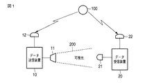
図1に示すように、可視光通信システムは、データ送信装置10及びデータ受信装置20から構成されている。本実施形態の可視光通信システムは、例えば車両と道路上の照明灯との可視光通信を行なうシステムや、船舶と灯台との可視光通信を行なうシステムなどに適用できる。
As shown in FIG. 1, the visible light communication system includes a
データ送信装置10は、LED(発光ダイオード)素子を使用するLED照明器11からの可視光200を搬送波としてデータ(可視光データと表記する場合がある)を送信する。ここで、データ送信装置10は、可視光200である搬送波にデジタルの送信データを直接重畳させるベースバンド方式の可視光送信を行なう。データ送信装置10は、例えば、LED照明器11を有する道路上の照明灯に組み込まれている。
The
また、データ受信装置20は、フォトセンサやCMOSセンサ等の受光素子21により可視光200を受信し、可視光200に重畳されている送信データを復調して出力する。データ受信装置20は、例えば、道路上を走行する車両に搭載されている。
The
本実施形態では、データ送信装置10及びデータ受信装置20はそれぞれ、GPS(global positioning system)人工衛星100が発信しているGPS信号を受信するGPS受信器12,22を有する。データ送信装置10及びデータ受信装置20はそれぞれ、GPS受信器12,22により受信したGPS信号に含まれる高精度の時計データを取得する。即ち、データ送信装置10及びデータ受信装置20はそれぞれ、GPS信号の時計データに同期して送受信動作を実行する。
In the present embodiment, each of the
(データ送信装置とデータ受信装置)
図3は、データ送信装置10の要部を示すブロック図である。
(Data transmission device and data reception device)
FIG. 3 is a block diagram illustrating a main part of the
データ送信装置10は、時計処理部13と、同期タイミング生成部14と、送信データ作成部15と、変調部16と、送信データ出力部17と、LED駆動部18と、電源部19とを有する。
The
時計処理部13は時計回路を含み、GPS受信器12により受信したGPS信号から時計データを抽出し、当該時計データに基づいて時計回路から出力される時計データを調整して出力する。同期タイミング生成部14は、時計処理部13から出力される時計データに基づいて同期送信タイミング信号を生成する。送信データ出力部17は、同期送信タイミング信号に同期して、データ受信装置20との間で予め設定される送信タイミングで、送信データ(可視光データ)をLED駆動部18に出力する。
The
送信データ作成部15は、例えば図示しないサーバから転送された送信データTDから所定の送信データフレームを作成する。変調部16は、送信データ作成部15により作成された送信データフレームを可視光通信用に変調した送信データ(可視光データ)を出力する。
The transmission
LED駆動部18は、送信データ出力部17から予め設定された送信タイミングで出力される送信データ(可視光データ)に応じてLED照明器11の駆動電流を制御する。これにより、LED照明器11は、送信データTD(可視光データ)を重畳した可視光200を発光する。電源部19は、LED駆動部18及びそれ以外の要素13〜17に対して電源を供給する。
The LED drive unit 18 controls the drive current of the
図4は、データ受信装置20の要部を示すブロック図である。
FIG. 4 is a block diagram showing a main part of the
データ受信装置20は、時計処理部23と、同期遅延算出部24と、距離算出部25と、復調部26と、データ出力部27と、データ入力部28と、電気信号変換部29と、電源部30とを有する。
The
時計処理部23は時計回路を含み、GPS受信器22により受信したGPS信号から時計データを抽出し、当該時計データに基づいて時計回路から出力される時計データを調整して出力する。同期遅延算出部24は、時計データに基づいて予め設定される送信タイミング(GPS受信同期信号GS)と、データ入力部28から出力されるデータ信号の受信タイミングとを比較し、その遅延時間Tを算出する。
The
距離算出部25は、同期遅延算出部24により算出される遅延時間Tに基づいて、データ送信装置10とデータ受信装置20との距離を算出し、その距離データDDを出力する。同期遅延算出部24及び距離算出部25は、マイクロプロセッサ及びソフトウェアから構成されている。
The
電気信号変換部29は、受光素子21により受光される可視光200を電気信号に変換する。データ入力部28は、電気信号変換部29からの電気信号に対する波形整形処理やノイズ除去処理などの信号処理を実行し、可視光データ(送信データ)を復元するためのデータ信号を抽出する。復調部26は、データ入力部28からのデータ信号から可視光データ(送信データ)を復調する。データ出力部27は、復調部26により復調された送信データから、例えば文字や画像等の所定のフォーマットの受信データRDに変換して出力する。電源部30は、電気信号変換部29及びそれ以外の要素23〜28に対して電源を供給する。
The
(送受信動作と距離算出処理)
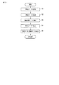
以下、図2のタイミングチャート及び図5のフローチャートを参照して、本実施形態のデータ送受信動作と距離算出処理を説明する。
(Transmission / reception operation and distance calculation processing)
Hereinafter, with reference to the timing chart of FIG. 2 and the flowchart of FIG.
まず、データ送信装置10は、LED照明器11から送信データTD(可視光データ)を重畳した可視光200を発光する。このとき、データ送信装置10は、前述したように、GPS信号の時計データに基づいて生成される同期送信タイミング信号に同期し、データ受信装置20との間で予め設定される送信タイミングで送信データ(可視光データ)を送信する。
First, the
一方、データ受信装置20は、受光素子21により送信された可視光200を受信し、データ入力部28により可視光データ(送信データ)を復元するためのデータ信号を抽出する。即ち、図5に示すように、データ受信装置20は、GPS信号の時計データに同期した可視光データを受信する(ステップS1)。データ受信装置20は、復調部26により可視光データ(送信データTD)を復調し、データ出力部27から受信データRDを出力する(ステップS2)。
On the other hand, the
ここで、本実施形態では、データ送信装置10及びデータ受信装置20はそれぞれ、GPS受信器12、22からの高精度の時計データに同期して送信及び受信動作を実行している。データ送信装置10は、GPS信号の時計データに基づいて、データ受信装置20との間で予め設定される送信タイミングで送信データ(可視光データ)を送信する。
Here, in the present embodiment, the
データ受信装置20では、同期遅延算出部24は、図2に示すように、GPS信号の時計データに基づいて予め設定される送信タイミングをGPS受信同期信号GSとして取得する。これにより、同期遅延算出部24は、図2に示すように、送信タイミング(GPS受信同期信号GS)と、実際の受信タイミング(可視光同期受信データRD)との遅延時間Tを示す遅延時間データを算出する(ステップS3)。
In the
さらに、データ受信装置20では、距離算出部25は、同期遅延算出部24により算出される遅延時間Tに基づいて、データ送信装置10とデータ受信装置20との距離を算出する(ステップS4)。具体的には、距離算出部25は、計算式「遅延時間T×空間伝播速度C=距離(m)」により、その距離データDDを算出する。ここで、空間伝播速度Cとは、可視光200の伝播速度である。
Further, in the
以上のようにして本実施形態の可視光通信システムによれば、データ受信装置20は、データ送信装置10から送信された送信データTD(可視光データ)に対応する受信データRDと共に、距離データDDを算出して出力する(ステップS5)。この距離データDDは、データ送信装置10とデータ受信装置20との距離を示すデータである。
As described above, according to the visible light communication system of the present embodiment, the
本実施形態の可視光通信システムを、例えば車両と道路上の照明灯との可視光通信を行なうシステムに適用した場合に、車両に搭載されたデータ受信装置20は、移動中の車両と可視光データを送信する照明灯との距離を出力できる。照明灯に設けられたデータ送信装置10は、可視光データにより照明灯の位置情報を送信できる。このため、移動中の車両は、照明灯の位置(固定位置)に対する距離の変化をリアルタイムで認識することが可能となり、例えば照明灯の位置まで到達できる時間を把握できる。このような効果については、本実施形態の可視光通信システムを、例えば船舶と灯台との可視光通信を行なうシステムに適用した場合でも同様である。
When the visible light communication system of the present embodiment is applied to, for example, a system that performs visible light communication between a vehicle and an illuminating lamp on a road, the
また、本実施形態の可視光通信システムを、例えば複数の車両間での可視光通信を行なうシステムに適用した場合に、車両間の距離の変化をリアルタイムで出力できる。従って、例えば距離データDDにより、相互間の接近距離が許容範囲を超えたことを検知して、車両の速度を自動的に低下させる衝突回避用システムを構築することが可能である。このような衝突回避用システムが車両に搭載されていれば、車両間の衝突回避を実現できる。 Moreover, when the visible light communication system of this embodiment is applied to a system that performs visible light communication between a plurality of vehicles, for example, a change in the distance between the vehicles can be output in real time. Therefore, for example, it is possible to construct a collision avoidance system that automatically reduces the vehicle speed by detecting that the approaching distance exceeds the allowable range based on the distance data DD. If such a collision avoidance system is mounted on a vehicle, collision avoidance between the vehicles can be realized.
なお、本実施形態において、送受信装置10,20においてGPS信号に基づいて同期する時計データを使用する場合について説明したが、GPS信号の代わりに電波時計データを利用しても良い。但し、一般的に、電波時計データは、GPS信号に含まれる時計データと比較して精度が低い。
In the present embodiment, the case where the transmitting / receiving
また、データ送信装置10は、データを送信する場合に、予め予告的に次の送信時間を示す送信時間データを送信データに付加してもよい。これにより、データ受信装置20は、送信タイミングを正確に取得することが可能となる。
Further, when transmitting data, the
[第2の実施形態]
図6は、本実施形態の可視光通信システムの構成を示す図である。
[Second Embodiment]
FIG. 6 is a diagram illustrating a configuration of the visible light communication system according to the present embodiment.
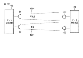
図6に示すように、本実施形態の可視光通信システムは、一方(便宜的にA側)のデータ送受信装置40Aと、他方(便宜的にB側)のデータ送受信装置40Bとから構成されている。
As shown in FIG. 6, the visible light communication system according to the present embodiment is composed of one (for convenience, A side) data transmission /
A側のデータ送受信装置40Aは、LED(発光ダイオード)素子を使用するLED照明器41Aからの可視光300Aを搬送波としてデータ(可視光データ)を送信する。また、A側のデータ送受信装置40Aは、フォトセンサやCMOSセンサ等の受光素子42Aにより可視光300Bを受信し、可視光300Bに重畳されている送信データを復調して出力する。
The A-side data transmitting / receiving
同様に、B側のデータ送受信装置40Bは、LED(発光ダイオード)素子を使用するLED照明器41Bからの可視光300Bを搬送波としてデータ(可視光データ)を送信する。また、B側のデータ送受信装置40Bは、フォトセンサやCMOSセンサ等の受光素子42Bにより可視光300Aを受信し、可視光300Aに重畳されている送信データを復調して出力する。
Similarly, the data transmission /
(データ送受信装置)
図8は、データ送受信装置40A,40Bの要部を示すブロック図である。両者は、同一構成であるため、便宜的にA側のデータ送受信装置40Aの場合について説明する。
(Data transceiver)
FIG. 8 is a block diagram showing a main part of the data transmitting / receiving
図8に示すように、データ送受信装置40Aは、送信データ作成部43Aと、変調部44Aと、送信データ出力部45Aと、LED駆動部46Aと、遅延時間算出部47Aと、距離算出部48Aと、電気信号変換部49Aと、データ入力部50Aと、復調部51Aと、受信データ出力部52Aと、遅延制御部53Aとを有する。
As shown in FIG. 8, the data transmitting / receiving
送信データ作成部43Aは、例えば図示しないサーバから転送された送信データTD-Aから所定の送信データフレームを作成する。変調部44Aは、送信データ作成部43Aにより作成された送信データフレームを可視光通信用に変調した送信データ(可視光データ)を出力する。送信データ出力部45Aは、変調部44Aにより変調された送信データまたは後述する返信データをLED駆動部46Aに出力する。返信データの場合には、送信データ出力部45Aは、遅延制御部53Aの制御に基づいて、データ受信後の予め設定された固定遅延時間を介して返信データをLED駆動部46Aに出力する。
For example, the transmission
LED駆動部46Aは、送信データ出力部45Aからの送信データ又は返信データに応じてLED照明器41Aの駆動電流を制御する。これにより、LED照明器41Aは、送信データ又は返信データを重畳した可視光300Aを発光する。電気信号変換部49Aは、受光素子42Aにより可視光300Bを受光し、その受光信号を電気信号に変換する。
The
データ入力部50Aは、電気信号変換部49Aからの電気信号に対する波形整形処理やノイズ除去処理などの信号処理を実行し、可視光データ(送信データ)を復元するためのデータ信号を抽出する。復調部51Aは、データ入力部50Aからのデータ信号から可視光データ(送信データ)を復調する。受信データ出力部52Aは、復調部51Aにより復調された送信データから、例えば文字や画像等の所定のフォーマットの受信データRD-Aに変換して出力する。
The
遅延時間算出部47Aは、送信データ出力部45Aからのデータ送信タイミングと、データ入力部50Aからの受信タイミング(返信データ)との遅延時間(送受信遅延時間T)を算出する。距離算出部48Aは、遅延時間算出部47Aにより算出される送受信遅延時間Tに基づいて、データ送受信装置40Bとの距離を算出し、その距離データDDを出力する。なお、遅延時間算出部47A及び距離算出部48Aは、マイクロプロセッサ及びソフトウェアから構成されている。
The delay
(送受信動作と距離算出処理)
以下、図7のタイミングチャート及び図9のフローチャートを参照して、本実施形態のデータ送受信動作と距離算出処理を説明する。
(Transmission / reception operation and distance calculation processing)
Hereinafter, the data transmission / reception operation and the distance calculation process of this embodiment will be described with reference to the timing chart of FIG. 7 and the flowchart of FIG.
図7に示すように、データ送受信装置40Aは、LED照明器41Aから発光される可視光300Aに重畳した送信データTD-Aを送信する(ステップS11)。他方のデータ送受信装置40Bは、データ送受信装置40Aから送信された可視光300Aを受光素子42Bにより受信し、送信データTD-Aを復調して受信データRD-Bを出力する(図8を参照)。この場合、図7に示すように、送信データTD-Aの送信タイミングと、受信データRD-Bの受信タイミングとは、空間光伝播速度に応じた空間遅延時間zを有する。
As shown in FIG. 7, the data transmitter /
本実施形態では、他方のデータ送受信装置40Bは、受信データRD-Bに応じた返信データを送信データ作成部(43B)により作成し、LED照明器41Bから発光される可視光300Bに重畳した送信データTD-Bとして送信する。このとき、返信データ(送信データTD-B)は、遅延制御部(53B)の制御に基づいて、データ受信後の予め設定された固定遅延時間tだけ遅延して送信される。
In the present embodiment, the other data transmission /
一方のデータ送受信装置40Aは、データ送受信装置40Bから送信された可視光300Bを受光素子42Aにより受信し、返信データ(送信データTD-B)を復調して受信データRD-Aとして出力する(ステップS12)。ここで、図7に示すように、データ送受信装置40Aでは、遅延時間算出部47Aは、送信データTD-Aの送信タイミングと返信データ(受信データRD-A)の受信タイミングとの送受信遅延時間Tを算出する(ステップS13)。即ち、最初に一方のデータ送受信装置40Aからデータ送信した時点から、他方のデータ送受信装置40Bからの返信データを受信した時点までの送受信遅延時間Tを計測する。
One data transmitter /
次に、データ送受信装置40Aでは、距離算出部48Aは、遅延時間算出部47Aにより算出される送受信遅延時間Tに基づいて、データ送受信装置40Bとの距離を算出する(ステップS14)。具体的には、距離算出部48Aは、計算式「(送受信遅延時間T−固定値円時間t)/2×空間伝播速度C=距離(m)」により、その距離データDDを算出する。即ち、予め決められた固定遅延時間tを除いた時間が、データ送受信装置40Aからデータ送受信装置40Bまでの送信遅延時間と、その逆方向の返信遅延時間となる。従って、往復のデータ通信遅延時間を求めて、この1/2の値と空間光伝播速度Cから、データ送受信装置40A,40B間の距離を求めることができる。この場合、データ送受信装置40A,40Bの各内部における電気信号の処理遅延時間等を考慮して、通信遅延時間を補正することで距離を高精度に算出することが可能となる。
Next, in the data transmission /
以上のようにして本実施形態の可視光通信システムによれば、データ送受信装置40A,40Bはそれぞれ、受信データRD-A,RD-B共に、相手側との距離を示す距離データDDを出力する(ステップS15)。即ち、データ送受信装置40A,40Bはそれぞれ、最初にデータを送信した送信タイミングと、相手側からの返信データの受信タイミングとの送受信遅延時間に基づいて、相互間の距離を示す距離データDDを算出できる。
As described above, according to the visible light communication system of the present embodiment, the data transmitting / receiving
本実施形態の可視光通信システムを、それぞれデータ送受信装置を搭載する車両間で可視光通信を行なうシステムに適用すれば、移動中の各車両はそれぞれ、相互間の距離の変化をリアルタイムで認識することが可能となる。これにより、相互間の接近距離が許容範囲を超えたことを検知して、車両の速度を自動的に低下させる衝突回避用システムを構築することが可能である。このような衝突回避用システムが車両に搭載されていれば、車両間の衝突回避を実現できる。 If the visible light communication system of the present embodiment is applied to a system that performs visible light communication between vehicles each equipped with a data transmitting / receiving device, each moving vehicle recognizes a change in distance between each other in real time. It becomes possible. Accordingly, it is possible to construct a collision avoidance system that detects that the approach distance between the vehicles exceeds the allowable range and automatically reduces the speed of the vehicle. If such a collision avoidance system is mounted on a vehicle, collision avoidance between the vehicles can be realized.
なお、データ送受信装置40A(または40B)は、最初にデータを送信する場合に、予め予告的に次の送信時間を示す送信時間データを送信データに付加してもよい。これにより、データ送受信装置40B(または40A)は、返信データを送信するタイミングを安定化させることが可能となる。
Note that when transmitting data for the first time, the data transmitting / receiving
[第3の実施形態]
図10は、本実施形態の可視光通信システムの構成を示す図である。
[Third Embodiment]
FIG. 10 is a diagram illustrating a configuration of the visible light communication system according to the present embodiment.
図10に示すように、可視光通信システムは、データ送信装置60及びデータ受信装置80から構成されている。データ送信装置10は、LED(発光ダイオード)素子を使用するLED照明器61からの可視光400を搬送波として送信データを変調して送信する。また、データ送信装置10は、並行して音波発生器62からも音波500を搬送波として送信データを変調して送信する。
As shown in FIG. 10, the visible light communication system includes a
データ受信装置80は、フォトセンサやCMOSセンサ等の受光素子81により可視光400を受信し、可視光400に重畳されている送信データ(可視光データ)を復調して出力する。また、データ受信装置80は、マイクロホン等を受音素子82により音波500を受信し、音波500に重畳されている音波データを復調して出力する。
The
(データ送信装置とデータ受信装置)
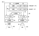
図12は、データ送信装置60の要部を示すブロック図である。
(Data transmission device and data reception device)
FIG. 12 is a block diagram illustrating a main part of the
データ送信装置60は、送信データ作成部63,65と、変調部64,66と、送信データ出力部67,69と、LED駆動部68と、音波駆動部70とを有する。送信データ作成部63は、例えば図示しないサーバから転送された可視光送信データTDから所定の送信データフレームを作成する。一方、送信データ作成部65は、図示しないサーバから転送された音波送信データSTから送信データフレームを作成する。
The
変調部64は、送信データ作成部63により作成された送信データフレーム(可視光送信データTD)を変調し、送信データ出力部67に出力する。変調部66は、送信データ作成部65により作成された送信データフレーム(音波送信データST)を変調し、送信データ出力部69に出力する。送信データ出力部67,69は、可視光データ(可視光400)と音波データ(音波500)を同時に出力させるために、出力同期部71からの同期信号に同期して動作する。
The
LED駆動部68は、送信データ出力部67から出力される可視光送信データ(送信データTDの変調データ)に応じてLED照明器61の駆動電流を制御する。これにより、LED照明器61は、可視光送信データを重畳した可視光400を発光する。音波駆動部70は、送信データ出力部69から出力される音波送信データ(送信データSTの変調データ)に応じてスピーカまたは超音波発生器等の音波発生器62を駆動制御する。これにより、音波発生器62は、音波送信データを重畳した音波500を発生する。
The
図13は、データ受信装置80の要部を示すブロック図である。
FIG. 13 is a block diagram showing a main part of the
データ受信装置80は、電気信号変換部83と、データ入力部84と、復調部85と、データ出力部86とを有する。電気信号変換部83は、受光素子81により受光される可視光400を電気信号に変換する。データ入力部84は、電気信号変換部83からの電気信号に対する波形整形処理やノイズ除去処理などの信号処理を実行し、可視光データを復元するためのデータ信号を抽出する。復調部85は、データ入力部84からのデータ信号から可視光データ(送信データTD)を復調する。データ出力部86は、復調部85により復調された送信データから、例えば文字や画像等の所定のフォーマットの受信データ(可視光受信データ)RDに変換して出力する。
The
一方、データ受信装置80は、電気信号変換部87と、データ入力部88と、復調部89と、データ出力部90とを有する。電気信号変換部87は、マイクロホン等の受音素子82により音波500を受信し、その音波信号を電気信号に変換する。データ入力部88は、音波信号(電気信号)に対する波形整形処理やノイズ除去処理などの信号処理を実行し、音波データを復元するためのデータ信号を抽出する。復調部89は、データ入力部88からのデータ信号から音波データ(送信データST)を復調する。データ出力部90は、復調部89により復調された送信データから、例えば文字や画像等の所定のフォーマットの受信データ(音波受信データ)SRに変換して出力する。
On the other hand, the
さらに、データ受信装置80は、遅延時間算出部91及び距離算出部92を有する。遅延時間算出部91は、データ入力部84からの可視光データの受信タイミングと、データ入力部88からの音波データの受信タイミングとの遅延時間Tを算出する。距離算出部25は、遅延時間算出部91により算出される遅延時間Tに基づいて、データ送信装置60とデータ受信装置80との距離を算出し、その距離データDDを出力する。なお、遅延時間算出部91及び距離算出部92は、マイクロプロセッサ及びソフトウェアから構成されている。
Further, the
(送受信動作と距離算出処理)
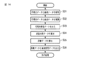
以下、図11のタイミングチャート及び図14のフローチャートを参照して、本実施形態のデータ送受信動作と距離算出処理を説明する。
(Transmission / reception operation and distance calculation processing)
Hereinafter, the data transmission / reception operation and the distance calculation process of this embodiment will be described with reference to the timing chart of FIG. 11 and the flowchart of FIG.
まず、データ送信装置60は、LED照明器61から可視光データ(送信データTD)を重畳した可視光400を送信する。ここで、同時タイミングで、データ送信装置60は、音波発生器62からも音波500を搬送波として音波データ(送信データST)を送信する。
First, the
一方、データ受信装置20は、受光素子81により送信された可視光400を受信し、また受音素子82により音波500を受信する(ステップS21)。データ受信装置20は、復調部85,89により、可視光送信データおよび音波データを復調する(ステップS22)。さらに、データ受信装置20は、データ出力部86から可視光受信データRDを出力する(ステップS23)。
On the other hand, the
図11に示すように、遅延時間算出部91は、可視光受信データRDの受信タイミングと、音波受信データSRの受信タイミングとの遅延時間Tを算出する(ステップS24)。即ち、可視光受信データRD及び音波受信データSRは、データ送信装置60から同時の送信タイミングで送信された可視光データ及び音波データを復調したものである。
As illustrated in FIG. 11, the delay
距離算出部92は、算出された遅延時間Tに基づいて、データ送信装置60とデータ受信装置80との距離を算出する(ステップS25)。具体的には、距離算出部92は、計算式「遅延時間T×音波伝播速度P=距離(m)」により、その距離データDDを算出する。ここで、音波伝播速度Pとは、音波500の伝播速度である。データ受信装置80は、距離データDDと音波受信データSRを出力する(ステップS26)。ここで、音波受信データSRは、可視光受信データRDと比較して、遅延時間Tだけ遅れて出力される。
The
以上のようにして本実施形態の可視光通信システムによれば、可視光400の空間光伝播速度Cに対して、音波500の空間伝播速度Pは極めて遅いため、その伝播速度差から距離を算出することができる。この場合、さらに算出した距離データDDから空間光伝播速度Cの遅延分を補正することで、距離データDDを高精度で算出できる。
As described above, according to the visible light communication system of the present embodiment, the spatial propagation speed P of the
なお、本実施形態において、音波発生器62から発生する音波500は、超音波などのように聴音できない周波数の音波でも良い。
In the present embodiment, the
また、本実施形態の可視光通信システムでは、可視光送信データ(TD)と音波送信データ(ST)は、同時タイミングで送信される同一内容のデータである。本実施形態の変形例として、音波送信データ(ST)は、可視光送信データ(TD)のデータ内容を通知するデータでも良い。本変形例の可視光通信システムであれば、例えば、データ送信装置60から案内情報を可視光送信データ(TD)として配信するシステムに適用した場合に、ユーザは携帯型機器に組み込まれたデータ受信装置80で受信する音波により、可視光送信データ(TD)として配信される案内情報の内容を音声で認識できる。
Moreover, in the visible light communication system of this embodiment, visible light transmission data (TD) and sound wave transmission data (ST) are the data of the same content transmitted at the same timing. As a modification of the present embodiment, the sound wave transmission data (ST) may be data notifying the data content of the visible light transmission data (TD). In the case of the visible light communication system according to the present modification, for example, when applied to a system that distributes guide information as visible light transmission data (TD) from the
本発明のいくつかの実施形態を説明したが、これらの実施形態は、例として提示したものであり、発明の範囲を限定することは意図していない。これら新規な実施形態は、その他の様々な形態で実施されることが可能であり、発明の要旨を逸脱しない範囲で、種々の省略、置き換え、変更を行うことができる。これら実施形態やその変形は、発明の範囲や要旨に含まれるとともに、特許請求の範囲に記載された発明とその均等の範囲に含まれる。 Although several embodiments of the present invention have been described, these embodiments are presented by way of example and are not intended to limit the scope of the invention. These novel embodiments can be implemented in various other forms, and various omissions, replacements, and changes can be made without departing from the scope of the invention. These embodiments and modifications thereof are included in the scope and gist of the invention, and are included in the invention described in the claims and the equivalents thereof.
10…データ送信装置、11…LED照明器、12…GPS受信器、
20…データ受信装置、21…受光素子、22…GPS受信器、
40A…データ送受信装置、41A…LED照明器、42A…受光素子、
40B…データ送受信装置、41B…LED照明器、42B…受光素子、
60…データ送信装置、61…LED照明器、62…音波発生器、
80…データ受信装置、81…受光素子、82…受音素子。
10 ... Data transmission device, 11 ... LED illuminator, 12 ... GPS receiver,
20 ... Data receiver, 21 ... Light receiving element, 22 ... GPS receiver,
40A ... Data transmitting / receiving device, 41A ... LED illuminator, 42A ... Light receiving element,
40B ... Data transmitting / receiving device, 41B ... LED illuminator, 42B ... Light receiving element,
60 ... Data transmission device, 61 ... LED illuminator, 62 ... Sound wave generator,
80: Data receiving device, 81: Light receiving element, 82: Sound receiving element.
Claims (11)
前記送信データの送信時間に対する前記受信手段での受信時間の遅延時間を示す遅延時間データを算出する遅延時間算出手段と、
前記遅延時間データに基づいて、前記送信データの送信位置と受信位置との距離を示す距離データを算出する距離算出手段と
を具備したことを特徴とする可視光通信装置。 Receiving means for receiving transmission data superimposed on visible light;
A delay time calculating means for calculating delay time data indicating a delay time of a reception time at the receiving means with respect to a transmission time of the transmission data;
A visible light communication apparatus comprising distance calculation means for calculating distance data indicating a distance between a transmission position and a reception position of the transmission data based on the delay time data.
前記遅延時間算出手段は、
前記送信時間を示す送信時間データ及び前記時間データに基づいて前記受信時間を示す受信時間データを取得し、
前記送信時間データと受信時間データを使用して前記遅延時間データを算出するように構成されていることを特徴とする請求項1に記載の可視光通信装置。 Having synchronization time acquisition means for acquiring time data for synchronizing with the transmission time from the outside,
The delay time calculating means includes
Obtaining transmission time data indicating the transmission time and reception time data indicating the reception time based on the time data,
The visible light communication apparatus according to claim 1, wherein the delay time data is calculated using the transmission time data and the reception time data.
GPSまたは電波時計システムから発信される時間信号を受信し、当該時間信号から前記時間データを生成するように構成されていることを特徴とする請求項2に記載の可視光通信装置。 The synchronization time acquisition means includes
The visible light communication apparatus according to claim 2, wherein the visible light communication apparatus is configured to receive a time signal transmitted from a GPS or a radio clock system and generate the time data from the time signal.
前記遅延時間算出手段は、
前記受信手段により前記送信データに対する返信データを受信した場合に、前記送信データの送信時間に対する前記返信データの受信時間の遅延時間を示す遅延時間データを算出するように構成されていることを特徴とする請求項1に記載の可視光通信装置。 Having transmission means for transmitting transmission data superimposed on visible light;
The delay time calculating means includes
When receiving the reply data for the transmission data by the receiving means, the delay time data indicating a delay time of the reception time of the reply data with respect to the transmission time of the transmission data is calculated. The visible light communication apparatus according to claim 1.
前記遅延時間データに基づいて、前記送信データの送信位置と前記送信データに対する前記返信データの送信位置との距離を示す距離データを算出するように構成されていることを特徴とする請求項4に記載の可視光通信装置。 The distance calculating means includes
The distance data indicating the distance between the transmission position of the transmission data and the transmission position of the reply data with respect to the transmission data is calculated based on the delay time data. The visible light communication apparatus described.
前記送信データの送信タイミングと同一タイミングで送信される音波データを受信する音波データ受信手段と、
前記可視光受信手段の受信タイミングと前記音波データ受信手段受信タイミングとの遅延時間を示す遅延時間データを算出する遅延時間算出手段と、
前記遅延時間データに基づいて、前記送信データの送信位置と受信位置との距離を示す距離データを算出する距離算出手段と
を具備したことを特徴とする可視光通信装置。 Visible light data receiving means for receiving transmission data superimposed on visible light;
Sound wave data receiving means for receiving sound wave data transmitted at the same timing as the transmission timing of the transmission data;
A delay time calculating means for calculating delay time data indicating a delay time between the reception timing of the visible light receiving means and the sound wave data receiving means;
A visible light communication apparatus comprising distance calculation means for calculating distance data indicating a distance between a transmission position and a reception position of the transmission data based on the delay time data.
前記遅延時間データ及び前記音波データを搬送する音波の空間音波伝播速度に基づいて、前記距離データを算出するように構成されていることを特徴とする請求項6に記載の可視光通信装置。 The distance calculating means includes
The visible light communication apparatus according to claim 6, wherein the distance data is calculated based on a spatial sound wave propagation speed of a sound wave carrying the delay time data and the sound wave data.
前記可視光通信装置の受信動作と前記データ送信装置の送信動作の同期時間を取得するための同期時間取得手段を有し、
前記可視光通信装置の前記遅延時間算出手段は、
前記同期時間取得手段により取得される前記データ送信装置の送信時間と前記可視光通信装置の受信時間との遅延時間を示す遅延時間データを算出するように構成されている可視光通信システム。 A visible light communication system comprising: the visible light communication device according to claim 1; and a data transmission device that transmits transmission data superimposed on visible light to the visible light communication device.
A synchronization time acquisition means for acquiring a synchronization time of the reception operation of the visible light communication device and the transmission operation of the data transmission device;
The delay time calculating means of the visible light communication device is
A visible light communication system configured to calculate delay time data indicating a delay time between a transmission time of the data transmission device acquired by the synchronization time acquisition means and a reception time of the visible light communication device.
前記第1及び第2の可視光送受信装置はそれぞれ、
前記受信手段により前記送信データに対する返信データを受信した場合に、前記送信データの送信時間に対する前記返信データの受信時間の遅延時間を示す遅延時間データを算出する遅延時間算出手段と、
前記遅延時間データに基づいて、前記送信データの送信位置と受信位置との距離を示す距離データを算出する距離算出手段と
を具備したことを特徴とする可視光通信システム。 A visible light communication system comprising first and second visible light transmission / reception devices including transmission means for transmitting transmission data superimposed on visible light and reception means for receiving the transmission data,
The first and second visible light transmitting / receiving devices are respectively
A delay time calculation means for calculating delay time data indicating a delay time of the reception time of the reply data with respect to a transmission time of the transmission data when the reception data is received by the reception means;
A visible light communication system comprising distance calculation means for calculating distance data indicating a distance between a transmission position and a reception position of the transmission data based on the delay time data.
前記送信データの送信時間に対する前記受信手段での受信時間の遅延時間を示す遅延時間データを算出する処理と、
前記遅延時間データに基づいて、前記送信データの送信位置と受信位置との距離を示す距離データを算出する処理と
を実行する可視光通信方法。 A visible light communication method applied to a visible light communication device having a receiving means for receiving transmission data superimposed on visible light,
A process of calculating delay time data indicating a delay time of a reception time at the reception unit with respect to a transmission time of the transmission data;
A visible light communication method for executing distance data indicating a distance between a transmission position and a reception position of the transmission data based on the delay time data.
前記送信データの送信時間に対する前記受信手段での受信時間の遅延時間を示す遅延時間データを算出する手段と、
前記遅延時間データに基づいて、前記送信データの送信位置と受信位置との距離を示す距離データを算出する手段と
して動作させるプログラム。 A program executed by a computer incorporated in a visible light communication device having a receiving means for receiving transmission data superimposed on visible light,
Means for calculating delay time data indicating a delay time of a reception time at the reception means with respect to a transmission time of the transmission data;
A program that operates as means for calculating distance data indicating a distance between a transmission position and a reception position of the transmission data based on the delay time data.
Priority Applications (1)
| Application Number | Priority Date | Filing Date | Title |
|---|---|---|---|
| JP2011023813A JP5579094B2 (en) | 2011-02-07 | 2011-02-07 | Visible light communication apparatus, visible light communication system, and visible light communication method |
Applications Claiming Priority (1)
| Application Number | Priority Date | Filing Date | Title |
|---|---|---|---|
| JP2011023813A JP5579094B2 (en) | 2011-02-07 | 2011-02-07 | Visible light communication apparatus, visible light communication system, and visible light communication method |
Publications (2)
| Publication Number | Publication Date |
|---|---|
| JP2012163431A true JP2012163431A (en) | 2012-08-30 |
| JP5579094B2 JP5579094B2 (en) | 2014-08-27 |
Family
ID=46842959
Family Applications (1)
| Application Number | Title | Priority Date | Filing Date |
|---|---|---|---|
| JP2011023813A Expired - Fee Related JP5579094B2 (en) | 2011-02-07 | 2011-02-07 | Visible light communication apparatus, visible light communication system, and visible light communication method |
Country Status (1)
| Country | Link |
|---|---|
| JP (1) | JP5579094B2 (en) |
Cited By (5)
| Publication number | Priority date | Publication date | Assignee | Title |
|---|---|---|---|---|
| KR101574509B1 (en) | 2014-11-24 | 2015-12-04 | 서울과학기술대학교 산학협력단 | The apparatus of muti data between marine object and ocean floor object with network zone |
| JP2016092670A (en) * | 2014-11-07 | 2016-05-23 | ヤマハ株式会社 | Transmitter |
| JP2017536059A (en) * | 2014-09-18 | 2017-11-30 | シソフト デ メキシコ,エス.エー.デ シー.ブイ. | Design and configuration of a system for two-way communication of digital data through visible light spectrum in unconfined media |
| JPWO2016194720A1 (en) * | 2015-06-05 | 2018-03-22 | ソニーセミコンダクタソリューションズ株式会社 | Signal processing apparatus and method, information processing apparatus and method, and program |
| CN113965259A (en) * | 2021-10-26 | 2022-01-21 | 中国矿业大学 | Single-base-station integrated communication and positioning integrated system based on visible light wireless transmission |
Citations (2)
| Publication number | Priority date | Publication date | Assignee | Title |
|---|---|---|---|---|
| JP2010107237A (en) * | 2008-10-28 | 2010-05-13 | Panasonic Electric Works Co Ltd | Navigation system |
| JP2010117212A (en) * | 2008-11-12 | 2010-05-27 | Toshiba Corp | Radio communications system, radio terminal, and radio base station apparatus |
-
2011
- 2011-02-07 JP JP2011023813A patent/JP5579094B2/en not_active Expired - Fee Related
Patent Citations (2)
| Publication number | Priority date | Publication date | Assignee | Title |
|---|---|---|---|---|
| JP2010107237A (en) * | 2008-10-28 | 2010-05-13 | Panasonic Electric Works Co Ltd | Navigation system |
| JP2010117212A (en) * | 2008-11-12 | 2010-05-27 | Toshiba Corp | Radio communications system, radio terminal, and radio base station apparatus |
Cited By (6)
| Publication number | Priority date | Publication date | Assignee | Title |
|---|---|---|---|---|
| JP2017536059A (en) * | 2014-09-18 | 2017-11-30 | シソフト デ メキシコ,エス.エー.デ シー.ブイ. | Design and configuration of a system for two-way communication of digital data through visible light spectrum in unconfined media |
| JP2016092670A (en) * | 2014-11-07 | 2016-05-23 | ヤマハ株式会社 | Transmitter |
| KR101574509B1 (en) | 2014-11-24 | 2015-12-04 | 서울과학기술대학교 산학협력단 | The apparatus of muti data between marine object and ocean floor object with network zone |
| JPWO2016194720A1 (en) * | 2015-06-05 | 2018-03-22 | ソニーセミコンダクタソリューションズ株式会社 | Signal processing apparatus and method, information processing apparatus and method, and program |
| CN113965259A (en) * | 2021-10-26 | 2022-01-21 | 中国矿业大学 | Single-base-station integrated communication and positioning integrated system based on visible light wireless transmission |
| CN113965259B (en) * | 2021-10-26 | 2022-11-11 | 中国矿业大学 | Single-base-station integrated communication and positioning integrated system based on visible light wireless transmission |
Also Published As
| Publication number | Publication date |
|---|---|
| JP5579094B2 (en) | 2014-08-27 |
Similar Documents
| Publication | Publication Date | Title |
|---|---|---|
| JP5579094B2 (en) | Visible light communication apparatus, visible light communication system, and visible light communication method | |
| RU2419104C2 (en) | Method and system to locate moving transport facilities | |
| US20120293373A1 (en) | Rtls system using tdo | |
| CA3023588A1 (en) | Positioning system | |
| US20200271780A1 (en) | Underwater acoustic tracking and two way messaging system | |
| DE602006020999D1 (en) | RFID SYSTEMS AND METHOD WITH INFRARED LOCALIZATION | |
| GB2497244A (en) | Method and apparatus for extending the coverage for positioning capability for a mobile receiver | |
| WO2007064726A3 (en) | Position determining apparatus and related method | |
| NZ584728A (en) | Positioning system using indoor transmitter | |
| JP2008538818A5 (en) | ||
| DE602004026547D1 (en) | INTEGRATED GPS INERTIA SYSTEM | |
| RU2010125205A (en) | METHOD AND DEVICE FOR PASSIVE LOCATION OF RADIO SIGNAL TRANSMITTERS | |
| US10732598B2 (en) | Method for the transformation of position information into a local coordinates system | |
| US10077985B2 (en) | Wireless positioning system, wireless positioning terminal, and point information transmitter | |
| EP2555439A4 (en) | Method and apparatus for generating reference signal | |
| CN104703274B (en) | Pseudo satellite, pseudolite wireless location method, system and device in a kind of band | |
| WO2017145789A1 (en) | Positioning device, communication device and positioning system | |
| US20220026518A1 (en) | System for localization of sound sources | |
| RU2012137774A (en) | DATA TRANSMISSION DEVICE, METHOD FOR MANAGING DATA TRANSFER AND DATA TRANSFER SYSTEM | |
| CN104320847A (en) | Low-power-consumption positioning method and system based on adjacency sensing and mobile base station | |
| JP2011117880A (en) | Wide area position specifying system | |
| JP2014042115A5 (en) | Short message communication terminal | |
| Akiyama et al. | Time synchronization method using visible light communication for smartphone localization | |
| JP2013149038A (en) | Transmitter and receiver | |
| KR101623452B1 (en) | System for estimating indoor position of ship |
Legal Events
| Date | Code | Title | Description |
|---|---|---|---|
| A621 | Written request for application examination |
Free format text: JAPANESE INTERMEDIATE CODE: A621 Effective date: 20130226 |
|
| RD04 | Notification of resignation of power of attorney |
Free format text: JAPANESE INTERMEDIATE CODE: A7424 Effective date: 20131205 |
|
| RD04 | Notification of resignation of power of attorney |
Free format text: JAPANESE INTERMEDIATE CODE: A7424 Effective date: 20131212 |
|
| RD04 | Notification of resignation of power of attorney |
Free format text: JAPANESE INTERMEDIATE CODE: A7424 Effective date: 20131219 |
|
| RD04 | Notification of resignation of power of attorney |
Free format text: JAPANESE INTERMEDIATE CODE: A7424 Effective date: 20131226 |
|
| RD04 | Notification of resignation of power of attorney |
Free format text: JAPANESE INTERMEDIATE CODE: A7424 Effective date: 20140109 |
|
| A131 | Notification of reasons for refusal |
Free format text: JAPANESE INTERMEDIATE CODE: A131 Effective date: 20140304 |
|
| A521 | Written amendment |
Free format text: JAPANESE INTERMEDIATE CODE: A523 Effective date: 20140422 |
|
| TRDD | Decision of grant or rejection written | ||
| A01 | Written decision to grant a patent or to grant a registration (utility model) |
Free format text: JAPANESE INTERMEDIATE CODE: A01 Effective date: 20140610 |
|
| A61 | First payment of annual fees (during grant procedure) |
Free format text: JAPANESE INTERMEDIATE CODE: A61 Effective date: 20140708 |
|
| LAPS | Cancellation because of no payment of annual fees |