JP2012160328A - Lighting apparatus - Google Patents
Lighting apparatus Download PDFInfo
- Publication number
- JP2012160328A JP2012160328A JP2011018833A JP2011018833A JP2012160328A JP 2012160328 A JP2012160328 A JP 2012160328A JP 2011018833 A JP2011018833 A JP 2011018833A JP 2011018833 A JP2011018833 A JP 2011018833A JP 2012160328 A JP2012160328 A JP 2012160328A
- Authority
- JP
- Japan
- Prior art keywords
- lighting
- circuit
- led light
- light sources
- series
- Prior art date
- Legal status (The legal status is an assumption and is not a legal conclusion. Google has not performed a legal analysis and makes no representation as to the accuracy of the status listed.)
- Pending
Links
Images


Landscapes
- Circuit Arrangement For Electric Light Sources In General (AREA)
Abstract
Description
本発明は、光源であるLED(発光ダイオード)を直列に接続した照明器具に関するものである。 The present invention relates to a lighting fixture in which LEDs (light emitting diodes) as light sources are connected in series.
従来より、複数個のLEDが直列に接続されている照明器具では、複数個のうちのいずれか少なくとも1個のLEDが断線で故障して無負荷状態になると、直列回路の一部が開放になる。このため、他の直列に接続されたLEDも同時に全て消灯してしまうという問題があった。
この対策として、全てのLEDに対して、LEDと一対にして個々に断線検出回路を設けることが行われている(例えば、特許文献1参照)。
Conventionally, in a lighting fixture in which a plurality of LEDs are connected in series, if at least one of the plurality of LEDs fails due to disconnection and becomes unloaded, a part of the series circuit is opened. Become. For this reason, there is a problem that all other LEDs connected in series are also extinguished simultaneously.
As a countermeasure, a disconnection detection circuit is provided for each LED as a pair with each LED (see, for example, Patent Document 1).
図9に示すように、特許文献1に記載の照明器具100では、複数個のLED101A、101B、…、101Nが直列に接続され、定電流源102に接続されている。各LED101A、101B…101Nには、各々に、電流迂回回路103A、103B…103N、保持回路104A、104B…104N、断線検出回路105A、105B…105Nが接続されている。
As shown in FIG. 9, in the
すなわち、LED101A、101B、…、101Nのいずれかの断線を検出した断線検出回路105A、105B…105Nの出力を、対応する保持回路104A、104B…104Nがそれを保持し、電流迂回回路103A、103B…103Nを導通さるようにした。
これにより、電流が故障したLED101A、101B、…、101Nの代わりに、対応する電流迂回回路103A、103B…103Nを流れるので、断線故障が他のLED101A、101B、…、101Nの発光に影響を及ぼさない。
That is, the output of the
This causes the current to flow through the corresponding
しかしながら、前述した特許文献1に記載の照明器具のように、LEDと一対にして個々に断線検出回路を設けると、回路構成が複雑になるとともに部品点数の増加から、コストアップを招くという問題があった。 However, when the disconnection detection circuit is individually provided as a pair with the LED as in the lighting apparatus described in Patent Document 1 described above, there is a problem that the circuit configuration becomes complicated and the cost increases due to an increase in the number of parts. there were.
本発明は、従来の問題を解決するためになされたもので、部品点数を増加させることなく簡単な回路構成で断線時に全てのLEDが消灯するのを防止できる照明器具を提供することを目的とする。 The present invention has been made to solve the conventional problems, and an object of the present invention is to provide a lighting apparatus that can prevent all LEDs from being turned off at the time of disconnection with a simple circuit configuration without increasing the number of parts. To do.
本発明の照明器具は、昇圧チョッパ回路と、前記昇圧チョッパ回路に接続され、LED光源を点灯させる複数の点灯回路と、を有し、前記各点灯回路は、少なくとも2つの異なる数のLED光源が直列に接続されたものである。 The lighting fixture of the present invention includes a boost chopper circuit and a plurality of lighting circuits connected to the boost chopper circuit and lighting the LED light source, and each lighting circuit includes at least two different numbers of LED light sources. They are connected in series.
また、本発明の照明器具は、前記複数の点灯回路のうちの少なくとも一つが、直列接続された前記LED光源に印加される電圧が入力電源電圧よりも高い第1の点灯回路であり、少なくとももう一つの点灯回路が、直列接続された前記LED光源に印加される電圧が入力電源電圧よりも低い第2の点灯回路であり、前記各点灯回路の無負荷を検出する検出回路を有するとともに、前記検出回路が無負荷を検出したときには、前記昇圧チョッパ回路を停止させるものである。 In the lighting fixture of the present invention, at least one of the plurality of lighting circuits is a first lighting circuit in which a voltage applied to the LED light sources connected in series is higher than an input power supply voltage, and at least another One lighting circuit is a second lighting circuit in which a voltage applied to the LED light sources connected in series is lower than an input power supply voltage, and includes a detection circuit that detects no load of each of the lighting circuits, and When the detection circuit detects no load, the boost chopper circuit is stopped.
さらに、本発明の照明器具は、前記複数の点灯回路のうちの少なくとも一つが、直列接続された前記LED光源に印加される電圧が入力電源電圧よりも高い第1の点灯回路であり、少なくとももう一つの点灯回路が、直列接続された前記LED光源に印加される電圧が入力電源電圧よりも低い第2の点灯回路であり、前記各点灯回路の無負荷を検出する検出回路を有するとともに、前記検出回路が無負荷を検出したときには、前記昇圧チョッパ電圧を前記第1の点灯回路が動作できなくなる電圧まで降圧するものである。 Furthermore, in the lighting fixture of the present invention, at least one of the plurality of lighting circuits is a first lighting circuit in which a voltage applied to the LED light sources connected in series is higher than an input power supply voltage, and at least another One lighting circuit is a second lighting circuit in which a voltage applied to the LED light sources connected in series is lower than an input power supply voltage, and includes a detection circuit that detects no load of each of the lighting circuits, and When the detection circuit detects no load, the step-up chopper voltage is stepped down to a voltage at which the first lighting circuit cannot operate.
本発明は、昇圧チョッパ回路で昇圧した電源に、複数のLED光源が異なる数で直列接続された点灯回路を複数設けることで、複数の点灯回路を一括で制御できる。また、電源部に関しては、同じ回路構成を複数設けなくてもよくなり、回路部品点数を削減できるという効果を有する照明器具を提供できる。 The present invention can collectively control a plurality of lighting circuits by providing a plurality of lighting circuits in which a plurality of LED light sources are connected in series with different numbers in a power source boosted by a boost chopper circuit. Moreover, regarding the power supply unit, it is not necessary to provide a plurality of the same circuit configurations, and it is possible to provide a luminaire having an effect of reducing the number of circuit components.
(第1実施形態)
以下、本発明に係る第1実施形態の照明器具について、図面を用いて説明する。
なお、以下の説明においては、照明器具を被取付面に取り付けて下方を照明する場合について説明する。従って、上(上方、上側等)は天井面側を意味し、下(下方、下側等)は床面側を意味する。
(First embodiment)
Hereinafter, the lighting fixture of 1st Embodiment which concerns on this invention is demonstrated using drawing.
In addition, in the following description, the case where a lighting fixture is attached to a to-be-attached surface and the downward direction is illuminated is demonstrated. Therefore, upper (upper, upper, etc.) means the ceiling surface side, and lower (lower, lower, etc.) means the floor surface side.
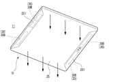
図1に示すように、本発明に係る第1実施形態の照明器具10は、被取付面である天井面11等に取り付けられて主に下方を照明するのに適する。
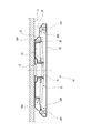
図2および図3に示すように、照明器具10は、天井面11に取り付けられている引っ掛けシーリング12に取り付けるための取付金具21を中央に有する、例えば正方形の板状の器具本体20を有する。
As shown in FIG. 1, the
As shown in FIGS. 2 and 3, the
器具本体20の上側(すなわち、天井面11側)には、LEDユニット30であるアッパーユニット30A、上枠24および上パネル23が設けられている。
また、器具本体20の下側(すなわち、照明方向側)には、LEDユニット30であるロアーユニット30B、反射部材である反射板26が設けられており、反射板26の下方には、受けた光を拡散する透光性のパネル25が取り付けられる。
LEDユニット30は、後述するように、直列に接続された複数個のLED光源31(図5参照)を有する。
なお、器具本体20の下面で反射板26との間には、LEDユニット30を点灯制御する制御部22が設けられている。
An
In addition, a
As will be described later, the
A
図4に示すように、アッパーユニット30Aは、器具本体20の上側において、四方外向きに設けられている。
また、ロアーユニット30Bは、器具本体20の下側において、2カ所に各々2個ずつ設けられており、内側へ光を照射するようになっている。
As shown in FIG. 4, the
Further, two
図2および図3に示したように、ロアーユニット30Bの下方には、パネル25が着脱可能に取り付けられる。パネル25は、照射された光を拡散するものであり、複数箇所に、光透過率が低いパネルカバー251が設けられている。
図1に示すように、パネルカバー251は、パネル25において器具本体20の中心に対して対称な端部付近の対向する2辺に沿って設けられている。
また、パネルカバー251は、ロアーユニット30Bが設けられている位置(図5参照)の下方に対応して設けられており、下方からロアーユニット30Bの影がパネル25に映らないようになっている。
As shown in FIGS. 2 and 3, the
As shown in FIG. 1, the
The
図5に示すように、制御部22に収容されている光源点灯用回路40は、直流電源部である昇圧チョッパ回路42、点灯制御部43および検出回路44を有する。
昇圧チョッパ回路42は、器具本体20の取付金具21を天井面11の引っ掛けシーリング12に取り付けることにより、天井面11の裏に配線されている商用電源13に電気的に接続される。
As illustrated in FIG. 5, the light
The step-up
点灯回路としての複数の点灯制御部43には、各々複数のLED光源31が直列に接続されたLED回路32が接続される。
すなわち、点灯制御部43は、第1の点灯制御部43A、第2の点灯制御部43Bおよび第3の点灯制御部43Cを有し、第1の点灯制御部43Aには第1のLED回路32A、第2の点灯制御部43Bには第2のLED回路32B、第3の点灯制御部43Cには第3のLED回路32Cが接続される。
An
That is, the
図5に示す例では、第1のLED回路32Aは、多数(例えば60粒)のLED光源31が直列に接続されて負荷容量が最も大きく、印加される電圧が入力電源電圧よりも高いDC140V以上が必要である。
第2の点灯制御部43Bは、中程度の数(例えば40粒)のLED光源31が直列に接続されて負荷容量が中程度で、印加される電圧は入力電源電圧よりも低いDC140V以下でよい。
第3の点灯制御部43Cは、小数(例えば10粒)のLED光源31が直列に接続されて負荷容量が小さく、印加される電圧は入力電源電圧よりも低いDC140V以下でよい。
In the example shown in FIG. 5, the
In the second
In the third
次に、図6に示すように、いずれかのLED光源31が切れて、検出回路44が対応する点灯制御部43の無負荷を検出したときには、昇圧チョッパ回路42に停止信号を送って、昇圧チョッパ回路44を停止させる。
これにより、点灯制御部43のうち、LED光源31の電圧(VF)の合計が入力電源電圧(DC140V)以上必要な第1の点灯回路43Aのみが停止する。
すなわち、昇圧チョッパ回路42で昇圧された電圧で点灯していた第1の点灯回路43Aに接続されている第1のLED回路32Aのみが消灯する。
そして、その他の第2の点灯回路制御部43Bおよび第3の点灯制御部43Cは、接続されるLED光源31の電圧(VF)の合計が入力電源電圧(DC140V)以下となっているので、昇圧チョッパ回路42を停止させても入力電源電圧で点灯を継続する。
Next, as shown in FIG. 6, when any
Thereby, only the
That is, only the
The other second lighting
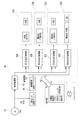
図7には、前述した照明器具10に適用した具体例が示されている。すなわち、LEDユニット30に白色LED光源31Aおよび電球色LED光源31Bを用いた場合が示されている。
白色LED光源31Aと電球色LED光源31Bとは、別経路で各々直列に接続されている。従って、白色LED光源31Aの光量と電球色LED光源31Bの光量との比率を変えることにより、光色の調整が可能となっている。
FIG. 7 shows a specific example applied to the
The white
第1のLED回路32Aは、全部で60粒のLED光源31が直列に接続されており、負荷容量が最も大きく、図5および図6で前述した第1の点灯制御部43Aに接続される。
また、第2のLED回路32Bは、全部で40粒のLED光源31が直列に接続されており、第1のLED回路32Aについで負荷容量が大きく、図5および図6で前述した第2の点灯制御部43Bに接続される。
The
Further, the
また、第3のLED回路32Cは、全部で10粒のLED光源31が直列に接続されており、最も負荷容量が小さい部類に属する。このため、図5および図6で前述した第3の点灯制御部43Cに接続される。
さらに、第4のLED回路32Dは、全部で5粒のLED光源31が直列に接続されており、最も負荷容量が小さい部類に属する。このため、図5および図6で前述した第3の点灯制御部43Cに接続される。
なお、第4のLED回路32Dはテレビ視聴時に適するものであり、第3のLED回路32Cとは別個に制御する必要があるので、第3の点灯制御部43Cをもう一つ別個に設けるのが望ましい。
In addition, the
Furthermore, the
Note that the
図7において、検出回路(制御電源回路ブロック)44がいずれかの点灯制御部43の無負荷を検出したときには、昇圧チョッパ回路42(PFC回路ブロック)に信号を送って、昇圧チョッパ回路42を停止させる。
これにより、点灯制御部43のうち、LED光源31の電圧(VF)の合計が入力電源電圧(DC140V)以上必要な第1の点灯回路43Aのみが停止する。
すなわち、昇圧チョッパ回路42で昇圧された電圧で点灯していた第1の点灯回路43Aに接続されている第1のLED回路32Aのみが停止して、第1のLED回路32AのLED光源31が消灯する。
そして、その他の第2の点灯回路制御部43Bおよび第3の点灯制御部43Cは、接続されるLED光源31の電圧(VF)の合計が入力電源電圧(DC140V)以下となるので、昇圧チョッパ回路42を停止させても入力電源電圧で点灯を継続する。
In FIG. 7, when the detection circuit (control power circuit block) 44 detects no load of any
Thereby, only the
That is, only the
The other second lighting
以上、説明した本発明に係る第1実施形態の照明器具10によれば、昇圧チョッパ回路42で昇圧した電源に、複数のLED光源31が異なる数で直列接続された点灯制御部43を複数設けることで、同じ粒数用の回路を複数設ける必要がなくなる。これにより、回路部品点数を削減できるとともに、複数の点灯制御部43を一括で制御できる。
また、電源部に関しては、同じ回路構成を複数設けなくてもよくなり、回路部品点数を削減できる。
As described above, according to the
Further, regarding the power supply unit, it is not necessary to provide a plurality of the same circuit configurations, and the number of circuit components can be reduced.
また、検出回路44が、LED光源31が無負荷若しくは過電圧となった異常を検出すると、昇圧チョッパ回路42を停止させる。
これにより、点灯制御部43のうち、LED光源31の電圧(VF)の合計が入力電源電圧(DC140V)以上必要な第1の点灯制御部43Aのみが停止する。
すなわち、昇圧チョッパ回路42で昇圧された電圧で点灯していた第1の点灯制御部43Aに接続されている複数のLED光源31のみが消灯する。
その他の点灯制御部(43B、43C)は、接続されるLED光源31の電圧(VF)の合計が入力電源電圧(DC140V)以下となるので、昇圧チョッパ回路42を停止させても入力電源電圧で点灯を継続できる。
これにより、LED光源31が無負荷若しくは過電圧となった異常を検出したときでも、全てのLED光源31が消灯するのを回避できる。また、入力電源電圧で点灯できる第2の点灯回路43Bに接続されたLED光源31が消灯していた場合には、ある範囲まで、不具合のあるLED回路32を検出しやすくなる。
Further, when the
Thereby, only the 1st
That is, only the plurality of
In the other lighting control units (43B, 43C), since the sum of the voltages (VF) of the
Thereby, even when the abnormality which the
(第2実施形態)
次に、本発明に係る第2実施形態の照明器具について説明する。
なお、前述した第1実施形態にかかる照明器具10と共通する部位には同じ符号を付して、重複する説明を省略することとする。
(Second Embodiment)
Next, the lighting fixture of 2nd Embodiment which concerns on this invention is demonstrated.
In addition, the same code | symbol is attached | subjected to the site | part which is common in the
図8に示すように、第2実施形態の照明器具10Bでは、検出回路44がいずれかの点灯制御部43の無負荷を検出したときには、昇圧チョッパ電圧を第1の点灯制御部43Aが動作できなくなる電圧まで降圧するものである。
As shown in FIG. 8, in the
以上、説明した本発明に係る第2実施形態の照明器具10Bによれば、点灯制御部43のうち、LED光源31の電圧(VF)の合計が入力電源電圧(DC140V)以上必要な第1の点灯制御部43Aのみが停止する。
すなわち、昇圧チョッパ回路42で昇圧された電圧で点灯していた第1の点灯制御部43Aに接続されている第1のLED回路32AのLED光源31のみが消灯する。
その他の点灯制御部43は、接続されるLED光源31の電圧(VF)の合計が入力電源電圧(DC140V)以下となる第2の点灯制御部43B、第3の点灯制御部43Cとしておくことにより、昇圧チョッパ回路42を降圧しても入力電源電圧で点灯を継続できる。
これにより、LED光源31が無負荷若しくは過電圧となった異常を検出したときでも、全てのLED光源31が消灯するのを回避できる。また、入力電源電圧で点灯できる第2の点灯制御部43Bや第3の点灯制御部43Cに接続されたLED光源31が消灯していた場合には、ある範囲まで、不具合のあるLEDユニットを検出しやすくなる。
As mentioned above, according to the
That is, only the
The other
Thereby, even when the abnormality which the
なお、本発明の照明器具は、前述した各実施形態に限定されるものでなく、適宜な変形、改良等が可能である。
例えば、前述した実施形態において、アッパーユニット30Aおよびロアーユニット30Bの配置、本数、搭載するLED光源31の粒数等は、例示したものに限らず、他のものにも適用可能である。
In addition, the lighting fixture of this invention is not limited to each embodiment mentioned above, A suitable deformation | transformation, improvement, etc. are possible.
For example, in the embodiment described above, the arrangement and number of the
また、前述した実施形態においては、第1の点灯制御部43A、第2の点灯制御部43B、第3の点灯制御部43Cを各々1個ずつ設けた場合を例示したが、個数は限定するものではなく、複数個設けることもできる。
In the above-described embodiment, the case where one each of the first
10,10B 照明器具
31 LED光源
42 昇圧チョッパ回路
43 点灯制御部(点灯回路)
43A 第1の点灯制御部(第1の点灯回路)
43B 第2の点灯制御部(第2の点灯回路)
44 検出回路
10,
43A 1st lighting control part (1st lighting circuit)
43B 2nd lighting control part (2nd lighting circuit)
44 Detection circuit
Claims (3)
LED光源を点灯させる複数の点灯回路と、を有し、
前記各点灯回路には少なくとも2つの異なる数のLED光源が直列に接続された照明器具。 A boost chopper circuit;
A plurality of lighting circuits for lighting the LED light source,
A lighting fixture in which at least two different numbers of LED light sources are connected in series to each lighting circuit.
前記複数の点灯回路のうちの少なくとも一つが、直列接続された前記LED光源に印加される電圧が入力電源電圧よりも高い第1の点灯回路であり、
少なくとももう一つの点灯回路が、直列接続された前記LED光源に印加される電圧が入力電源電圧よりも低い第2の点灯回路であり、
前記各点灯回路の無負荷を検出する検出回路を有するとともに、
前記検出回路が無負荷を検出したときには、前記昇圧チョッパ回路を停止させる照明器具。 The lighting fixture according to claim 1,
At least one of the plurality of lighting circuits is a first lighting circuit in which a voltage applied to the LED light sources connected in series is higher than an input power supply voltage,
At least another lighting circuit is a second lighting circuit in which a voltage applied to the LED light sources connected in series is lower than an input power supply voltage;
While having a detection circuit for detecting no load of each lighting circuit,
A lighting fixture that stops the step-up chopper circuit when the detection circuit detects no load.
前記複数の点灯回路のうちの少なくとも一つが、直列接続された前記LED光源に印加される電圧が入力電源電圧よりも高い第1の点灯回路であり、
少なくとももう一つの点灯回路が、直列接続された前記LED光源に印加される電圧が入力電源電圧よりも低い第2の点灯回路であり、
前記各点灯回路の無負荷を検出する検出回路を有するとともに、
前記検出回路が無負荷を検出したときには、前記昇圧チョッパ電圧を前記第1の点灯回路が動作できなくなる電圧まで降圧する照明器具。 The lighting fixture according to claim 1,
At least one of the plurality of lighting circuits is a first lighting circuit in which a voltage applied to the LED light sources connected in series is higher than an input power supply voltage,
At least another lighting circuit is a second lighting circuit in which a voltage applied to the LED light sources connected in series is lower than an input power supply voltage;
While having a detection circuit for detecting no load of each lighting circuit,
A lighting fixture that steps down the boost chopper voltage to a voltage at which the first lighting circuit cannot operate when the detection circuit detects no load.
Priority Applications (1)
| Application Number | Priority Date | Filing Date | Title |
|---|---|---|---|
| JP2011018833A JP2012160328A (en) | 2011-01-31 | 2011-01-31 | Lighting apparatus |
Applications Claiming Priority (1)
| Application Number | Priority Date | Filing Date | Title |
|---|---|---|---|
| JP2011018833A JP2012160328A (en) | 2011-01-31 | 2011-01-31 | Lighting apparatus |
Publications (1)
| Publication Number | Publication Date |
|---|---|
| JP2012160328A true JP2012160328A (en) | 2012-08-23 |
Family
ID=46840705
Family Applications (1)
| Application Number | Title | Priority Date | Filing Date |
|---|---|---|---|
| JP2011018833A Pending JP2012160328A (en) | 2011-01-31 | 2011-01-31 | Lighting apparatus |
Country Status (1)
| Country | Link |
|---|---|
| JP (1) | JP2012160328A (en) |
Cited By (1)
| Publication number | Priority date | Publication date | Assignee | Title |
|---|---|---|---|---|
| CN105873297A (en) * | 2016-06-02 | 2016-08-17 | 李广元 | Light control circuit and lamp applying light control circuit |
Citations (6)
| Publication number | Priority date | Publication date | Assignee | Title |
|---|---|---|---|---|
| JP2007529872A (en) * | 2004-03-15 | 2007-10-25 | カラー・キネティックス・インコーポレーテッド | Power control method and apparatus |
| JP2008130513A (en) * | 2006-11-24 | 2008-06-05 | Matsushita Electric Works Ltd | Led lighting circuit and illumination fixture using it |
| JP2008130295A (en) * | 2006-11-17 | 2008-06-05 | Matsushita Electric Works Ltd | Led lighting circuit and illumination fixture using it |
| JP2008243641A (en) * | 2007-03-28 | 2008-10-09 | Mitsubishi Electric Corp | Lighting device, display device, guide light device, and illuminating apparatus |
| JP2008258428A (en) * | 2007-04-05 | 2008-10-23 | Sharp Corp | Driving circuit of white led for illumination, illuminator with the same, and electronic device |
| JP2010011608A (en) * | 2008-06-26 | 2010-01-14 | Mitsumi Electric Co Ltd | Semiconductor integrated circuit for power supply control |
-
2011
- 2011-01-31 JP JP2011018833A patent/JP2012160328A/en active Pending
Patent Citations (6)
| Publication number | Priority date | Publication date | Assignee | Title |
|---|---|---|---|---|
| JP2007529872A (en) * | 2004-03-15 | 2007-10-25 | カラー・キネティックス・インコーポレーテッド | Power control method and apparatus |
| JP2008130295A (en) * | 2006-11-17 | 2008-06-05 | Matsushita Electric Works Ltd | Led lighting circuit and illumination fixture using it |
| JP2008130513A (en) * | 2006-11-24 | 2008-06-05 | Matsushita Electric Works Ltd | Led lighting circuit and illumination fixture using it |
| JP2008243641A (en) * | 2007-03-28 | 2008-10-09 | Mitsubishi Electric Corp | Lighting device, display device, guide light device, and illuminating apparatus |
| JP2008258428A (en) * | 2007-04-05 | 2008-10-23 | Sharp Corp | Driving circuit of white led for illumination, illuminator with the same, and electronic device |
| JP2010011608A (en) * | 2008-06-26 | 2010-01-14 | Mitsumi Electric Co Ltd | Semiconductor integrated circuit for power supply control |
Cited By (1)
| Publication number | Priority date | Publication date | Assignee | Title |
|---|---|---|---|---|
| CN105873297A (en) * | 2016-06-02 | 2016-08-17 | 李广元 | Light control circuit and lamp applying light control circuit |
Similar Documents
| Publication | Publication Date | Title |
|---|---|---|
| JP6216713B2 (en) | Flat panel lighting system and drive circuit | |
| US9338845B2 (en) | LED arrangement | |
| WO2013039811A1 (en) | Solid-state lighting apparatus and methods using current diversion controlled by lighting device bias states | |
| US20070236946A1 (en) | Lighting Assembly Having An Integrated Solid-State Light Emitting Device | |
| WO2011039690A1 (en) | Modular luminaire and lighting system | |
| US9775214B2 (en) | Battery backup system for LED luminaire | |
| JP5799242B2 (en) | Lighting device and lighting fixture | |
| EP2838318A1 (en) | Lighting circuit and luminiare | |
| JP2011222123A (en) | Lighting device | |
| JP2012243458A (en) | Lighting device and lighting fixture | |
| KR200483092Y1 (en) | Scalable LED lighting device | |
| JP5598660B2 (en) | Power supply device and lighting device | |
| JP5756914B2 (en) | Lighting device | |
| JP2012160328A (en) | Lighting apparatus | |
| US20140159579A1 (en) | Lighting module and lighting apparatus using lighting module | |
| JP2015103354A (en) | Lighting device and a luminaire including the lighting device | |
| JP5881415B2 (en) | Lighting device | |
| JP5615198B2 (en) | Elevator car interior lighting equipment | |
| JP2010257872A (en) | Illumination device | |
| JP2014089888A (en) | Led lighting device | |
| EP2922368B1 (en) | Multi-color interior aircraft light unit and passenger transport vehicle comprising the same | |
| JP5771771B2 (en) | Lighting apparatus and lighting apparatus using the same | |
| JP5599331B2 (en) | lighting equipment | |
| JP4971101B2 (en) | Light-emitting diode dimming system | |
| JP6300073B2 (en) | Lighting system |
Legal Events
| Date | Code | Title | Description |
|---|---|---|---|
| A621 | Written request for application examination |
Free format text: JAPANESE INTERMEDIATE CODE: A621 Effective date: 20131113 |
|
| RD04 | Notification of resignation of power of attorney |
Free format text: JAPANESE INTERMEDIATE CODE: A7424 Effective date: 20131225 |
|
| A131 | Notification of reasons for refusal |
Free format text: JAPANESE INTERMEDIATE CODE: A131 Effective date: 20140715 |
|
| A521 | Written amendment |
Free format text: JAPANESE INTERMEDIATE CODE: A523 Effective date: 20140908 |
|
| A711 | Notification of change in applicant |
Free format text: JAPANESE INTERMEDIATE CODE: A711 Effective date: 20141008 |
|
| A131 | Notification of reasons for refusal |
Free format text: JAPANESE INTERMEDIATE CODE: A131 Effective date: 20141202 |
|
| A521 | Written amendment |
Free format text: JAPANESE INTERMEDIATE CODE: A523 Effective date: 20150114 |
|
| RD02 | Notification of acceptance of power of attorney |
Free format text: JAPANESE INTERMEDIATE CODE: A7422 Effective date: 20150119 |
|
| A02 | Decision of refusal |
Free format text: JAPANESE INTERMEDIATE CODE: A02 Effective date: 20150407 |