JP2012147937A - Laser therapy apparatus, laser therapy system and assessment method - Google Patents
Laser therapy apparatus, laser therapy system and assessment method Download PDFInfo
- Publication number
- JP2012147937A JP2012147937A JP2011008733A JP2011008733A JP2012147937A JP 2012147937 A JP2012147937 A JP 2012147937A JP 2011008733 A JP2011008733 A JP 2011008733A JP 2011008733 A JP2011008733 A JP 2011008733A JP 2012147937 A JP2012147937 A JP 2012147937A
- Authority
- JP
- Japan
- Prior art keywords
- laser
- state
- end portion
- tissue
- laser catheter
- Prior art date
- Legal status (The legal status is an assumption and is not a legal conclusion. Google has not performed a legal analysis and makes no representation as to the accuracy of the status listed.)
- Pending
Links
Images


Classifications
-
- A—HUMAN NECESSITIES
- A61—MEDICAL OR VETERINARY SCIENCE; HYGIENE
- A61B—DIAGNOSIS; SURGERY; IDENTIFICATION
- A61B18/00—Surgical instruments, devices or methods for transferring non-mechanical forms of energy to or from the body
- A61B18/18—Surgical instruments, devices or methods for transferring non-mechanical forms of energy to or from the body by applying electromagnetic radiation, e.g. microwaves
- A61B18/20—Surgical instruments, devices or methods for transferring non-mechanical forms of energy to or from the body by applying electromagnetic radiation, e.g. microwaves using laser
-
- A—HUMAN NECESSITIES
- A61—MEDICAL OR VETERINARY SCIENCE; HYGIENE
- A61N—ELECTROTHERAPY; MAGNETOTHERAPY; RADIATION THERAPY; ULTRASOUND THERAPY
- A61N5/00—Radiation therapy
- A61N5/06—Radiation therapy using light
- A61N5/0613—Apparatus adapted for a specific treatment
-
- A—HUMAN NECESSITIES
- A61—MEDICAL OR VETERINARY SCIENCE; HYGIENE
- A61B—DIAGNOSIS; SURGERY; IDENTIFICATION
- A61B18/00—Surgical instruments, devices or methods for transferring non-mechanical forms of energy to or from the body
- A61B18/18—Surgical instruments, devices or methods for transferring non-mechanical forms of energy to or from the body by applying electromagnetic radiation, e.g. microwaves
- A61B18/20—Surgical instruments, devices or methods for transferring non-mechanical forms of energy to or from the body by applying electromagnetic radiation, e.g. microwaves using laser
- A61B18/22—Surgical instruments, devices or methods for transferring non-mechanical forms of energy to or from the body by applying electromagnetic radiation, e.g. microwaves using laser the beam being directed along or through a flexible conduit, e.g. an optical fibre; Couplings or hand-pieces therefor
- A61B18/24—Surgical instruments, devices or methods for transferring non-mechanical forms of energy to or from the body by applying electromagnetic radiation, e.g. microwaves using laser the beam being directed along or through a flexible conduit, e.g. an optical fibre; Couplings or hand-pieces therefor with a catheter
-
- A—HUMAN NECESSITIES
- A61—MEDICAL OR VETERINARY SCIENCE; HYGIENE
- A61M—DEVICES FOR INTRODUCING MEDIA INTO, OR ONTO, THE BODY; DEVICES FOR TRANSDUCING BODY MEDIA OR FOR TAKING MEDIA FROM THE BODY; DEVICES FOR PRODUCING OR ENDING SLEEP OR STUPOR
- A61M25/00—Catheters; Hollow probes
- A61M25/01—Introducing, guiding, advancing, emplacing or holding catheters
-
- A—HUMAN NECESSITIES
- A61—MEDICAL OR VETERINARY SCIENCE; HYGIENE
- A61N—ELECTROTHERAPY; MAGNETOTHERAPY; RADIATION THERAPY; ULTRASOUND THERAPY
- A61N5/00—Radiation therapy
- A61N5/06—Radiation therapy using light
- A61N5/0601—Apparatus for use inside the body
-
- A—HUMAN NECESSITIES
- A61—MEDICAL OR VETERINARY SCIENCE; HYGIENE
- A61N—ELECTROTHERAPY; MAGNETOTHERAPY; RADIATION THERAPY; ULTRASOUND THERAPY
- A61N5/00—Radiation therapy
- A61N5/06—Radiation therapy using light
- A61N5/0613—Apparatus adapted for a specific treatment
- A61N5/062—Photodynamic therapy, i.e. excitation of an agent
-
- A—HUMAN NECESSITIES
- A61—MEDICAL OR VETERINARY SCIENCE; HYGIENE
- A61B—DIAGNOSIS; SURGERY; IDENTIFICATION
- A61B18/00—Surgical instruments, devices or methods for transferring non-mechanical forms of energy to or from the body
- A61B2018/00315—Surgical instruments, devices or methods for transferring non-mechanical forms of energy to or from the body for treatment of particular body parts
- A61B2018/00345—Vascular system
- A61B2018/00351—Heart
-
- A—HUMAN NECESSITIES
- A61—MEDICAL OR VETERINARY SCIENCE; HYGIENE
- A61B—DIAGNOSIS; SURGERY; IDENTIFICATION
- A61B18/00—Surgical instruments, devices or methods for transferring non-mechanical forms of energy to or from the body
- A61B2018/00636—Sensing and controlling the application of energy
- A61B2018/00642—Sensing and controlling the application of energy with feedback, i.e. closed loop control
- A61B2018/00648—Sensing and controlling the application of energy with feedback, i.e. closed loop control using more than one sensed parameter
-
- A—HUMAN NECESSITIES
- A61—MEDICAL OR VETERINARY SCIENCE; HYGIENE
- A61B—DIAGNOSIS; SURGERY; IDENTIFICATION
- A61B90/00—Instruments, implements or accessories specially adapted for surgery or diagnosis and not covered by any of the groups A61B1/00 - A61B50/00, e.g. for luxation treatment or for protecting wound edges
- A61B90/06—Measuring instruments not otherwise provided for
- A61B2090/064—Measuring instruments not otherwise provided for for measuring force, pressure or mechanical tension
- A61B2090/065—Measuring instruments not otherwise provided for for measuring force, pressure or mechanical tension for measuring contact or contact pressure
-
- A—HUMAN NECESSITIES
- A61—MEDICAL OR VETERINARY SCIENCE; HYGIENE
- A61B—DIAGNOSIS; SURGERY; IDENTIFICATION
- A61B5/00—Measuring for diagnostic purposes; Identification of persons
- A61B5/06—Devices, other than using radiation, for detecting or locating foreign bodies ; determining position of probes within or on the body of the patient
Landscapes
- Health & Medical Sciences (AREA)
- Life Sciences & Earth Sciences (AREA)
- Engineering & Computer Science (AREA)
- Biomedical Technology (AREA)
- Public Health (AREA)
- Veterinary Medicine (AREA)
- Animal Behavior & Ethology (AREA)
- General Health & Medical Sciences (AREA)
- Nuclear Medicine, Radiotherapy & Molecular Imaging (AREA)
- Physics & Mathematics (AREA)
- Surgery (AREA)
- Radiology & Medical Imaging (AREA)
- Pathology (AREA)
- Heart & Thoracic Surgery (AREA)
- Medical Informatics (AREA)
- Otolaryngology (AREA)
- Electromagnetism (AREA)
- Optics & Photonics (AREA)
- Biophysics (AREA)
- Molecular Biology (AREA)
- Pulmonology (AREA)
- Anesthesiology (AREA)
- Hematology (AREA)
- Radiation-Therapy Devices (AREA)
- Laser Surgery Devices (AREA)
- Media Introduction/Drainage Providing Device (AREA)
Abstract
Description
本発明は、レーザカテーテルを使って被治療組織に対して治療するレーザ治療装置、レーザ治療システム及びこれらの装置やシステムに適用可能な判別方法に関する。 The present invention relates to a laser treatment apparatus, a laser treatment system, and a discrimination method applicable to these apparatuses and systems for treating a treated tissue using a laser catheter.
頻脈性不整脈の一種として、心房細動が知られている。心房細動は、肺静脈と左心房との接合部付近に電気パルスを発生する異常興奮部位が出現し、この電気パルスの刺激によって左心房が細かく振動及び収縮することにより発生する。 Atrial fibrillation is known as a type of tachyarrhythmia. Atrial fibrillation occurs when an abnormal excitation site that generates an electric pulse appears near the junction between the pulmonary vein and the left atrium, and the left atrium vibrates and contracts finely by stimulation of the electric pulse.
心房細動治療法として、発明者らは、光線力学的治療(Photodynamic Therapy、以下「PDT」と記述する。)を適用することを提案してきた(例えば、特許文献1参照。)。PDTでは、光感受性薬剤が取り込まれた心筋組織にレーザカテーテルを用いて励起光を照射して、一重項酸素を発生させる。酸化力の強い一重項酸素は、異常興奮部位を取り囲む心筋組織に傷害を与えて、異常興奮部位から左心房への電気パルスの伝導を遮断(ブロック)する電気伝導ブロックを形成する。この結果、異常興奮部位と左心房との間の電気伝導が遮断され、左心房の異常な振動及び収縮が抑制される。 As an atrial fibrillation treatment method, the inventors have proposed to apply photodynamic therapy (hereinafter referred to as “PDT”) (for example, refer to Patent Document 1). In PDT, singlet oxygen is generated by irradiating myocardial tissue into which a photosensitizing agent has been incorporated with excitation light using a laser catheter. Singlet oxygen having strong oxidizing power damages the myocardial tissue surrounding the abnormally excited site, and forms an electrical conduction block that blocks (blocks) the conduction of electrical pulses from the abnormally excited site to the left atrium. As a result, electrical conduction between the abnormal excitation site and the left atrium is blocked, and abnormal vibration and contraction of the left atrium are suppressed.
光感受性薬剤は、特定の組織に選択的に集積する性質を持つ。そこで、一般には、患者に光感受性薬剤を投与してから所定時間(例えば8〜48時間)経過後、治療組織の光感受性薬剤濃度が高く他の組織や血中の光感受性薬剤濃度が低い状態、いわゆる光感受性薬剤のコントラストがついた状態となってから励起光を照射する。また、近年、光感受性薬剤の集積性を利用せず、光感受性薬剤が血液によって被治療組織にデリバリーされた時点で励起光を照射するPDTも提案されている。 Photosensitive drugs have the property of selectively accumulating in specific tissues. Therefore, in general, after a predetermined time (for example, 8 to 48 hours) has elapsed since the photosensitizing agent was administered to the patient, the photosensitizing agent concentration in the treated tissue is high and the photosensitizing agent concentration in other tissues or blood is low. The excitation light is irradiated after the contrast of the so-called photosensitizing agent is obtained. In recent years, a PDT that irradiates excitation light when the photosensitive drug is delivered to the tissue to be treated by blood without using the accumulation property of the photosensitive drug has been proposed.
循環器系疾患治療の分野では、安全性と確実性を担保するため、励起光を出射するレーザカテーテルの先端部の組織に対する接触状態を判別することは重要である。特許文献2及び3には、先端部の組織に対する接触状態を検出する技術が記載されている。特許文献2では、接触時の先端部の変形を戻り光より推定し、それにより先端部の組織に対する接触状態を検出している。特許文献3では、先端部に圧力センサを設け、それにより先端部の組織に対する接触状態を検出している。
In the field of cardiovascular disease treatment, in order to ensure safety and certainty, it is important to determine the contact state of the tip of the laser catheter that emits excitation light to the tissue.
本発明者らの知見によれば、レーザカテーテルの先端部が組織に埋没するほどの過度な押し付けは、術中の患者への負担が大きくなる上に、術後の副作用にも大きく関与することが判明している。しかし、特許文献2及び3に記載された技術を用いることで、レーザカテーテルの先端部が組織にかかっている圧力を評価することは可能であるが、埋没状態における圧力値の評価基準を設けない限り、医師等の施術者が埋没状態を認識するのは難しい。しかも、埋没状態と圧力値との関係は、すべての患者について一律に定められるものではなく、そこには個体差が存在するとも考えられる。また、特許文献2及び3に記載された技術では、圧力センサ等の治療には必要のないデバイスを実装する必要があるため、レーザカテーテルの構造が複雑化する。
According to the knowledge of the present inventors, excessive pressing to such an extent that the tip of the laser catheter is buried in the tissue increases the burden on the patient during the operation and may greatly contribute to side effects after the operation. It turns out. However, by using the techniques described in
以上のような事情に鑑み、本発明の目的は、レーザカテーテルの先端部が組織に対する埋没状態も含めた接触状態を判別することが可能なレーザ治療装置、レーザ治療システム及び判別方法を提供することにある。
本発明の別の目的は、そのような判別を簡単な構成で実現することができるレーザ治療装置、レーザ治療システム及び判別方法を提供することにある。
In view of the circumstances as described above, an object of the present invention is to provide a laser treatment apparatus, a laser treatment system, and a discrimination method capable of discriminating a contact state including a buried state of a tip of a laser catheter with respect to a tissue. It is in.
Another object of the present invention is to provide a laser treatment apparatus, a laser treatment system, and a discrimination method capable of realizing such discrimination with a simple configuration.
上記目的を達成するため、本発明の一形態に係るレーザ治療装置は、接続部と、出射部と、光学的状態検出部と、電気的状態検出部と、判別部とを有する。 In order to achieve the above object, a laser treatment apparatus according to an aspect of the present invention includes a connection unit, an emission unit, an optical state detection unit, an electrical state detection unit, and a determination unit.
接続部は、第1の端部及び第2の端部を有し、前記第1の端部の先端面よりレーザ光を出入射し、前記第1の端部の外周の軸方向に沿って設けられた電極を有するレーザカテーテルの前記第2の端部が接続される。
出射部は、前記接続部に接続された第2の端部にレーザ光を出射する。
光学的状態検出部は、前記接続部に接続された第2の端部からの戻り光を入射し、前記入射した戻り光の光学的状態を検出する。
電気的状態検出部は、前記接続部に接続された第2の端部を介して前記電極の電気的状態を検出する。
The connecting portion has a first end portion and a second end portion, and laser light enters and exits from the front end surface of the first end portion, along the axial direction of the outer periphery of the first end portion. The second end of a laser catheter having an electrode provided is connected.
The emission unit emits laser light to the second end connected to the connection unit.
The optical state detection unit receives return light from the second end connected to the connection unit, and detects an optical state of the incident return light.
The electrical state detection unit detects the electrical state of the electrode through the second end connected to the connection unit.
判別部は、前記検出された光学的状態及び前記電気的状態に基づき、前記第1の端部と前記レーザカテーテルを使って治療される被治療組織との接触状態を判別する。 The discriminating unit discriminates a contact state between the first end and the tissue to be treated using the laser catheter based on the detected optical state and the electrical state.
ここで、本発明は、前記光学的状態検出部は、前記入射した戻り光の強度を検出するものであり、前記電気的状態検出部は、前記電極の電位を検出するものであり、前記判別部は、前記検出された光強度が弱く、前記検出された電位が低いときには、前記第1の端部と前記被治療組織との接触状態が正常であると判別し、前記検出された光強度が弱く、前記検出された電位が高いときには、前記第1の端部が前記被治療組織に埋没していると判別し、前記検出された光強度が強く、前記検出された電位が高いときには、前記レーザカテーテルが被治療組織に対して沿うように接触した状態であると判別するように構成してもよい。 Here, in the present invention, the optical state detection unit detects the intensity of the incident return light, and the electrical state detection unit detects a potential of the electrode. A unit determines that the contact state between the first end and the tissue to be treated is normal when the detected light intensity is low and the detected potential is low, and the detected light intensity Is weak and the detected potential is high, it is determined that the first end is buried in the tissue to be treated, the detected light intensity is strong, and when the detected potential is high, You may comprise so that it may discriminate | determine that the said laser catheter is the state which contacted with respect to the to-be-treated tissue.
本発明では、レーザカテーテルからの戻り光の光学的状態を検出することに加えて、レーザカテーテルの第1の端部の外周の軸方向に沿って設けられた電極の電気的状態を検出することで、レーザカテーテルの先端部(第1の端部)が組織に対する埋没状態も含めた接触状態を判別することができる。また、電極は本来治療に用いられるものであり、圧力センサ等の治療には必要のないデバイスを実装する必要がないので、埋没状態も含めた接触状態の判別を簡単な構成で実現することができる。
本発明の一形態に係るレーザ治療システムは、レーザカテーテルと、接続部と、出射部と、光学的状態検出部と、電気的状態検出部と、判別部とを有する。
In the present invention, in addition to detecting the optical state of the return light from the laser catheter, detecting the electrical state of the electrodes provided along the axial direction of the outer periphery of the first end of the laser catheter Thus, it is possible to determine the contact state including the buried state of the tip (first end) of the laser catheter with respect to the tissue. In addition, since electrodes are originally used for treatment and there is no need to mount devices that are not necessary for treatment such as pressure sensors, it is possible to realize contact state discrimination including an embedded state with a simple configuration. it can.
A laser treatment system according to an aspect of the present invention includes a laser catheter, a connection unit, an emission unit, an optical state detection unit, an electrical state detection unit, and a determination unit.
レーザカテーテルは、第1の端部及び第2の端部を有し、前記第1の端部の先端面よりレーザ光を出入射し、前記第1の端部の外周に前記第1の端部の軸方向に沿って設けられた電極を有する。
接続部は、前記レーザカテーテルの第2の端部が接続される。
出射部は、前記接続部に接続された第2の端部にレーザ光を出射する。
光学的状態検出部は、前記接続部に接続された第2の端部からの戻り光を入射し、前記入射した戻り光の光学的状態を検出する。
電気的状態検出部は、前記接続部に接続された第2の端部を介して前記電極の電気的状態を検出する。
The laser catheter has a first end and a second end, a laser beam enters and exits from a distal end surface of the first end, and the first end is disposed on an outer periphery of the first end. And an electrode provided along the axial direction of the portion.
The connecting portion is connected to the second end of the laser catheter.
The emission unit emits laser light to the second end connected to the connection unit.
The optical state detection unit receives return light from the second end connected to the connection unit, and detects an optical state of the incident return light.
The electrical state detection unit detects the electrical state of the electrode through the second end connected to the connection unit.
判別部は、前記検出された光学的状態及び前記電気的状態に基づき、前記第1の端部と前記レーザカテーテルを使って治療される被治療組織との接触状態を判別する。
ここで、本発明は、前記レーザカテーテルに設けられた電極は、リング状の電極で構成してもよい。
The discriminating unit discriminates a contact state between the first end and the tissue to be treated using the laser catheter based on the detected optical state and the electrical state.
Here, in the present invention, the electrode provided on the laser catheter may be a ring-shaped electrode.
本発明の一形態に係る判別方法は、第1の端部及び第2の端部を有し、前記第1の端部の先端面よりレーザ光を出入射し、前記第1の端部の外周に前記第1の端部の軸方向に沿って設けられた電極を有するレーザカテーテルの前記第2の端部にレーザ光を出射し、前記第2の端部からの戻り光を入射して前記入射した戻り光の光学的状態を検出すると共に、前記電極の電気的状態を検出し、前記検出された光学的状態及び前記電気的状態に基づき、前記第1の端部と前記レーザカテーテルを使って治療される被治療組織との接触状態を判別する。 A determination method according to an aspect of the present invention includes a first end and a second end, a laser beam is emitted from a front end surface of the first end, and the first end is A laser beam is emitted to the second end of the laser catheter having an electrode provided on the outer periphery along the axial direction of the first end, and a return light from the second end is incident. An optical state of the incident return light is detected, and an electrical state of the electrode is detected. Based on the detected optical state and the electrical state, the first end portion and the laser catheter are connected to each other. The contact state with the treated tissue to be treated is discriminated.
本発明では、レーザカテーテルの先端部が組織に対する埋没状態も含めた接触状態を判別することができ、また埋没状態も含めた接触状態の判別を簡単な構成で実現することができる。 In the present invention, it is possible to determine the contact state including the embedded state of the tip of the laser catheter including the embedded state, and it is possible to realize the determination of the contact state including the embedded state with a simple configuration.
以下、図面を参照しながら、本発明の実施形態を説明する。本実施形態では、レーザ装置として光線力学的治療装置(以下「PDT装置」と記述する。)を用いるものとして説明する。
[システム全体の構成]
図1は、本発明の一実施形態に係るPDT装置を含めた治療システム全体を示す模式図である。
Hereinafter, embodiments of the present invention will be described with reference to the drawings. In the present embodiment, description will be made assuming that a photodynamic therapy device (hereinafter referred to as “PDT device”) is used as the laser device.
[Entire system configuration]
FIG. 1 is a schematic diagram showing an entire treatment system including a PDT apparatus according to an embodiment of the present invention.
PDT装置1は、PDT装置本体100と、PDT装置本体100に接続されたチューブ200と、チューブ200の先端に設けられたコネクタ(接続部)210とを有する。
The
チューブ200は、中空の柔らかい管であり、内蔵する装置付属光ファイバ201(図3参照。)を介して光を伝送可能であり、また内蔵する装置付属電気配線202(図3参照。)を介してレーザカテーテル300の先端部における電位の計測等が可能である。
コネクタ210には、レーザカテーテル300が着脱可能に接続される。
The
The
患者2には、光感受性薬剤が投与される。静脈注射により投与した場合、投与された光感受性薬剤は血液中に拡散し、さらに心筋組織等の組織に拡散する。光感受性薬剤は、静脈注射により治療に必要な分量を一括投与したり、点滴により継続的に投与したり、経口から一括又は継続的に投与したり、局所投与してもよい。光感受性薬剤とは、光の特定波長を吸収して励起し、蛍光を発する薬剤である。例えば、タラポルフィンナトリウム(レザフィリン(登録商標)、明治製菓株式会社)という薬剤がある。この薬剤のQ帯吸収波長は664nm前後に存在するため、この薬剤の励起光源としては、例えば600−800nm、好ましくは660−680nm、さらに好ましくは664±2nmを用いる。
図2は、心臓に挿入されたレーザカテーテルを示す模式図である。
FIG. 2 is a schematic view showing a laser catheter inserted into the heart.
レーザカテーテル300は、患者2の大腿静脈又は頸静脈を通して、心臓10の右心房14に挿入される。右心房14に到達したレーザカテーテル300は、中隔を貫通し左心房13に導かれる。
[PDT装置本体の構成]
図3は、PDT装置本体を示すブロック図である。
The
[Configuration of PDT device body]
FIG. 3 is a block diagram showing the PDT apparatus main body.
PDT装置本体100は、光源110と、光学系120と、光学的状態検出部130と、電位検出部135と、心電取得部140と、制御部150と、記憶部160と、表示部170と、操作部180とを有する。
The PDT apparatus
光源110は、光感受性薬剤の励起光を出力する。光源110が出力する光の波長は、光感受性薬剤のQ帯の吸収波長と等しい。例えばQ帯吸収波長が664nm前後の光感受性薬剤が用いられるとき、光源110として発振波長600−800nm、好ましくは660−680nm、さらに好ましくは664±2nmの半導体レーザが使用される。光源110が出力した励起光(レーザ光)は、光学系120によりレーザカテーテル300に入射する。
The
光学系120は、光源110が発する励起光を、装置付属光ファイバ201を介してコネクタ210に接続されたレーザカテーテル300に入射する。光学系120は、励起光が照射された光感受性薬剤が発する蛍光(戻り光)をレーザカテーテル300から取り出し、光学的状態検出部130に入射する。光学系120は、ショートパスフィルタ121と、第1のレンズ122と、偏光ビームスプリッタ(Polarizing Beam Splitter、以下「PBS」と記述する。)123と、ロングパスフィルタ124と、第2のレンズ125とを有する。
The
ショートパスフィルタ121は、カットオン波長670nmの短波長透過フィルタであり、レーザ光の長波側の輻射をカットする。光源110からの励起光は蛍光観察波長域(ピーク波長よりも長波側)に輻射成分をもつ。そこで、励起光の長波側の輻射成分を、レーザカテーテル300に集光する前段階でカットする。ショートパスフィルタ121を透過した励起光は、第1のレンズ122に入射する。
The
第1のレンズ122は、ショートパスフィルタ121より入射した励起光をレーザカテーテル300の一端面に集光する。また、第1のレンズ122は、レーザカテーテル300の先端部からの蛍光をPBS123に集光する。なお、光源110からの励起光の一部は、装置付属光ファイバ201のPDT装置本体100側端面や、コネクタ210内や、レーザカテーテル300の先端部で反射して正反射光としてPBS123に入射する。これら正反射光は、蛍光の検出にあたりノイズとなる。
The
PBS123は、第1のレンズ122より入射した光のうち、偏向の違いを利用してチューブ200内の光ファイバの端面で反射した正反射光を透過させて検出せずに、蛍光とその他の端面における正反射光を反射して検出器へと導く。PBS123を透過した蛍光は、ロングパスフィルタ124に入射する。
The
ロングパスフィルタ124は、PBS123より入射した光のうち、コネクタ210内及びレーザカテーテル300の先端部で反射した正反射光を透過せずに、蛍光のみを透過して検出器へと導く。ロングパスフィルタ124を透過した蛍光は、第2のレンズ125に入射する。
第2のレンズ125は、ロングパスフィルタ124より入射した蛍光を光学的状態検出部130に集光する。
The
The
光学的状態検出部130は、例えばリニアイメージセンサーであり、光学系120より入射した蛍光を分光検出する。すなわち、光学的状態検出部130は、励起波長の光と励起波長の光より長い光である光感受性薬剤の蛍光を検出する。光学的状態検出部130は、検出した蛍光の強度を電気信号として制御部150に出力する。
The optical
電位検出部135は、レーザカテーテル300の先端部における第1の電極に対する第2の電極(後述する。)の電位を検出する。電位検出部135は、検出した電位を電気信号として制御部150に出力する。
The
心電取得部140には、電極コード(図示せず)を介して電極パッド141が接続される。心電取得部140は、患者2に装着された電極パッド141と電極コードとを介して患者2の心電信号を取得し、取得した心電信号を制御部150に供給する。
制御部150は、PDT装置1内の各部を制御する。
An
The
制御部150は、光学的状態検出部130及び電位検出部135より取得した電気信号をもとに、レーザカテーテル300の組織に対する埋没状態も含めた接触状態を判別する。
The
制御部150は、光学的状態検出部130より取得した電気信号と心電取得部140より取得した心電信号とをもとに、電気伝導ブロックの形成の有無を判別する。
制御部150は、埋没状態も含めた接触状態の判別結果の情報を表示するための表示命令を出力する。
記憶部160は、不揮発性メモリであり、例えばフラッシュメモリ、HDD(Hard Disk Drive)、その他の固体メモリに設定される。
The
The
The
表示部170は、例えば液晶表示器等を用いた表示デバイスである。表示部170は、制御部150から表示命令を取得すると、表示命令に含まれる表示情報に基き、例えば埋没状態も含めた接触状態の判別結果に関する情報等を表示画面に表示する。
The
操作部180は、施術者からの入力操作による命令を受け付け、受け付けた命令を制御部150に出力する。命令とは、例えば、光源110が出力する励起光のオン・オフや強度の切り替え等に関する命令である。励起光の強度は、少なくとも、組織や血液に対し低侵襲な低パワー(例えば、光出力1mW以下)の第1の強度と、第1の強度のおよそ1000倍程度の強さの高パワーの第2の強度との2種類を選択可能である。第1の強度は、治療前に、薬剤濃度やレーザカテーテル300の接触状態をモニターする際に選択される。第2の強度は、実際の治療を行う際に選択される。
[レーザカテーテルの構成]
図4は、レーザカテーテルの外観を示す図であり、図5は、図4に示したレーザカテーテルの先端部の一部断面図、図6は、図5のA−A断面図である。
The
[Configuration of laser catheter]
4 is a view showing the appearance of the laser catheter, FIG. 5 is a partial cross-sectional view of the distal end portion of the laser catheter shown in FIG. 4, and FIG. 6 is a cross-sectional view taken along line AA of FIG.
レーザカテーテル300は、先端部(第1の端部)の端面から励起光を出射する。レーザカテーテル300は、カテーテルチューブ310と、第1の端部311と、第2の端部312と、支持部320と、光ファイバ330と、光学ウィンドウ340と、複数の電極351、352と、配線353とを有する。
The
カテーテルチューブ310は、中空の柔らかい管であり、患者2の心臓10の心筋組織の内壁に導かれる。カテーテルチューブ310は、光ファイバ330及び配線353を内蔵する。カテーテルチューブ310は、両端に第1の端部311と第2の端部312とを有する。
The
支持部320は、レーザカテーテル300の第1の端部311に設けられている。支持部320は、光ファイバ330及び光学ウィンドウ340をカテーテルチューブ310に対して保持する。第1の端部311である支持部320は、支持部320の外周に、その軸方向(図中X方向)に所定の間隔tを有するように複数の電極351、352が設けられている。複数の電極351、352は、例えばPtからなり、リング状の形状を有する。複数の電極351、352のうち一方の電極351は、例えば支持部320の最先端部まで位置している。電極351は、支持部320の端面部まで及んでいてもよい。逆に、電極351は、支持部320の最先端部と僅かに間隔を有していてもよい。例えば、複数の電極351、352のうち一方の電極351は、他方の電極352よりも幅が広く、また複数の電極351、352間の間隔tは、2mm程度とされている。複数の電極351、352間の間隔tやその他の寸法は、レーザカテーテル300の第1の端部311が組織に埋没したときに複数の電極351、352がそれぞれ組織に接触するが、例えばその際の第1の電極に対する第2の電極の電位の変化が検出できればよい。
The
複数の電極351、352は、それぞれの配線353を介して第2の端部312において装置付属電気配線202に接続され、PDT装置本体100の電位検出部135に接続される。例えば、電位検出部135は、心筋組織に接触した電極から、心筋組織の電位情報を検出している。また、電位検出部135は、電極351に所定の電圧を印加し、電極352の電位を検出することで、一対の電極351、352間の電位差を検出してもよい。電極352が組織に接触していないときには、検出される電極352に電位は低く、電極352が組織に接触していないときには、検出される電極352に電位は高い。
The plurality of
光ファイバ330は、例えば、コア径133μm且つ外形500μmやコア径200μm且つ外形350μmなどの1本の石英製ステップインデックスファイバである。光ファイバ330は、PDT装置1からの励起光を伝送する。光ファイバ330は、先端から、伝送した励起光を照射光301として光学ウィンドウ340へ出射する。照射光301のビーム径は、光ファイバ330の開口(NA)で定まる角度で増大する。光ファイバ330の先端は、この照射光301のビーム径が適切に増大するように加工される。光ファイバ330は、励起光が照射された組織に取り込まれた光感受性薬剤が発した蛍光をPDT装置1に伝送する。
The
光学ウィンドウ340は、レーザカテーテル300の先端部の最外部に光ファイバ330の先端と光学的に連続して設けられる。光学ウィンドウ340は、固形の透明材料、例えばBK7等の硝子材料からなる。光学ウィンドウ340は、光ファイバ330の先端から出射した照射光301を透過させる。光学ウィンドウ340は、光感受性薬剤が発した蛍光を光ファイバ330の先端に集光する。
[PDT装置の動作]
次に、以上のように構成されたPDT装置1の動作について説明する。
PDT装置1の動作の説明は、以下の順序で行うものとする。
(1)PDTの準備
(2)接触モニター動作
The
[Operation of PDT device]
Next, the operation of the
The operation of the
(1) Preparation of PDT (2) Contact monitor operation
接触モニター動作では、光源110は第1の強度で励起光を出力し、制御部150は光学的状態検出部130が検出する蛍光強度及び電位検出部135が検出する電位をもとにレーザカテーテル300の組織内壁に対する埋没状態も含めた接触状態を判別する。
(3)レーザ治療実施動作
In the contact monitoring operation, the
(3) Laser treatment operation
レーザ治療実施動作では、光源110は第2の強度で励起光を出力し、実際のレーザ治療が実施される。この動作においても、接触モニター動作と同様に、レーザカテーテル300の組織内壁に対する埋没状態も含めた接触状態を判別している。
以下では、これらの動作をさらに詳細に説明する。
[(1)PDTの準備]
In the laser treatment execution operation, the
In the following, these operations will be described in more detail.
[(1) Preparation for PDT]
まず、医師等の施術者により、レーザカテーテル300が患者2の大腿静脈又は頸静脈を通して心臓10に挿入される。レーザカテーテル300の先端部は、左心房13の心筋組織11内壁の肺静脈12近傍に配置される(図2参照)。
続いて、施術者により、各種レファレンスデータを参考に、患者2に光感受性薬剤が投与される。
[(2)接触モニター動作]
続いて、接触モニター動作が行われる。
図7は、レーザカテーテルの接触状態を示す模式図である。
First, an operator such as a doctor inserts the
Subsequently, the practitioner administers a photosensitive drug to the
[(2) Contact monitor operation]
Subsequently, a contact monitoring operation is performed.
FIG. 7 is a schematic diagram showing a contact state of the laser catheter.
レーザカテーテル300は、発光部位としての先端部(第1の端部)が心筋組織11の内壁に垂直に接触するように配置されるのが望ましい(図7(a)参照、以下「垂直接触状態」と記述する。)。これは、レーザカテーテル300の先端部から心房内血液15を排除して心房内血液15中の光感受性薬剤の活性化を抑えるためである。また、レーザカテーテル300の先端部を組織に直接接触させることで組織に存在している光感受性薬剤を選択的に活性化するためである。
The
しかしながら、実際には、レーザカテーテル300の先端部は、心筋組織11の内壁に垂直ではなく、図7(b)に示すように傾いて接触する場合がある。図7(c)に示すようにレーザカテーテル300の先端部は、心筋組織11の内壁に埋没する場合もあり、図7(d)に示すように傾いて埋没する場合もある。図7(e)に示すように、レーザカテーテル300の先端部は、心筋組織11の内壁に接触すらしない場合もある。
However, in actuality, the distal end portion of the
特に、図7(c)、(d)に示すように、レーザカテーテル300の先端部が心筋組織11の内壁に埋没した場合には、レーザカテーテル300の先端部を心筋組織11の内壁に過度な押し付けをしていることになる。このような過度な押し付けは、術中の患者への負担が大きくなる上に、術後の副作用にも大きく関与する。そこで、本実施形態における接触モニター動作では、制御部150が光学的状態検出部130が検出する蛍光強度及び電位検出部135が検出する電位をもとにレーザカテーテル300の組織内壁に対する埋没状態も含めた接触状態を判別している。
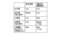
図8は、検出される蛍光強度及び電位と図7(a)〜(e)に示した接触状態との関係を示す表である。
In particular, as shown in FIGS. 7C and 7D, when the tip of the
FIG. 8 is a table showing the relationship between the detected fluorescence intensity and potential and the contact states shown in FIGS.
図7(a)に示すように、レーザカテーテル300の先端部が心筋組織11の内壁に垂直に接触している場合には、血液(薬剤濃度が組織よりも高い)が先端部と心筋組織11の内壁との間でほぼ排除されているため、光学的状態検出部130が検出する蛍光強度は弱い。この場合、電極352が組織に接触していないため、電位検出部135が検出する電極352の電位は低い。
As shown in FIG. 7A, when the tip of the
図7(b)に示すように、レーザカテーテル300の先端部が心筋組織11の内壁に斜めに接触している場合には、血液が先端部と心筋組織11の内壁との間に少し介在するため、光学的状態検出部130が検出する蛍光強度は中程度である。この場合、電極352が組織に接触していないため、電位検出部135が検出する電極352の電位は低い。
As shown in FIG. 7B, when the distal end portion of the
図7(c)に示すように、レーザカテーテル300の先端部が心筋組織11の内壁に垂直に埋没している場合には、血液が先端部と心筋組織11の内壁との間でほぼ排除されているため、光学的状態検出部130が検出する蛍光強度は弱い。この場合、電極352が組織に接触しているため、電位検出部135が検出する電極352の電位は高い。
As shown in FIG. 7C, when the distal end portion of the
図7(d)に示すように、レーザカテーテル300の先端部が心筋組織11の内壁に斜めに埋没している場合には、血液が先端部と心筋組織11の内壁との間でほぼ排除されているため、光学的状態検出部130が検出する蛍光強度は弱い。この場合、電極352が組織に少し接触しているため、電位検出部135が検出する電極352の電位は中程度から高いものとなる。
As shown in FIG. 7D, when the distal end portion of the
いずれにしても、レーザカテーテル300の先端部が心筋組織11の内壁に埋没している場合には、電位検出部135が検出する電極352の電位は低くはないので、電位検出部135が電極352の電位は低くはないことを検出することで、埋没の判別が可能である。
In any case, when the distal end portion of the
図7(e)に示すように、レーザカテーテル300の先端部が心筋組織11の内壁に接触していないときには、血液が先端部にほぼ存在しているため、光学的状態検出部130が検出する蛍光強度は強い。この場合、電極352が組織に接触している場合には、電位検出部135が検出する電極352の電位は高く、電極352が組織に少し接触していない場合には、電位検出部135が検出する電極352の電位は低い。いずれにしても、レーザカテーテル300の先端部が心筋組織11の内壁に接触していないときには、光学的状態検出部130が検出する蛍光強度は強いので、光学的状態検出部130が蛍光強度が強いことを検出することで、カテーテルが心筋組織に対して沿うように接触した状態の判別が可能である。また電位検出部135の情報だけでは、(e)の状態(電極352が心筋組織に接触している状態)と(c)と(d)の差異がわからないが、蛍光強度の情報を組み合わせることで、先端部の状態を判別することができる。
As shown in FIG. 7E, when the distal end portion of the
制御部150は、光学的状態検出部130及び電位検出部135より取得した電気信号をもとに、レーザカテーテル300の組織に対する埋没状態も含めた接触状態、すなわち上記の図7(a)〜(e)のうちいずれかの状態にあるかを判別する。例えば、制御部150は、図7(c)〜(e)の状態にあるときは、表示部170に所定の警告を表示する。その際に、制御部150は、図7(c)(d)と(e)とを区別するように表示してもよい。これにより、医師等の施術者は、埋没状態にあることを認識することができ、心筋組織に対する過剰な力を軽減することができる。従って、副作用の低減を図ることができ、患者の負担軽減にもつながり、更に周囲臓器への影響を防ぐことができる。なお、表示部への表示ではなく、所定の報知音によって医師等の施術者へ報知してもよい。施術者は、レーザカテーテル300に設けられたハンドピース等(図示せず。)を操作することにより、レーザカテーテル300の先端部の組織に対する接触状態を変更することができる。
[(3)レーザ治療実施動作]
Based on the electrical signals acquired from the optical
[(3) Laser treatment operation]
施術者は、操作部180を操作して高パワーの第2の強度での励起光出力命令を制御部150に入力する。制御部150は、励起光出力命令を取得すると、光源110に第2の強度での励起光出力命令を出力する。光源110は、制御部150より励起光出力命令を取得すると、第2の強度で励起光を出力する。光源110が出力した励起光は、光学系120及びレーザカテーテル300を介して組織に照射され、光線力学的治療が実施される。
The practitioner operates the
この動作においても、接触モニター動作と同様に、レーザカテーテル300の組織内壁に対する埋没状態も含めた接触状態を判別している。すなわち、制御部150は、光学的状態検出部130及び電位検出部135より取得した電気信号をもとに、レーザカテーテル300の組織に対する埋没状態も含めた接触状態、すなわち上記の図7(a)〜(e)のうちいずれかの状態にあるかを判別する。表示部170に所定の警告を表示する。これにより、上記と同様に、医師等の施術者は、埋没状態にあることを認識することができ、心筋組織に対する過剰な力を軽減することができる。
Also in this operation, as in the contact monitoring operation, the contact state including the embedded state of the
本実施形態においては、複数の電極351、352は本来治療(例えば簡易的な治療効果や接触状態の判別など)に用いられるものであり、圧力センサ等の治療には必要のないデバイスを実装する必要がないので、埋没状態も含めた接触状態の判別を簡単な構成で実現することができる。
本発明に係る実施形態は、以上説明した実施形態に限定されず、他の種々の形態が考えられる。
In the present embodiment, the plurality of
The embodiment according to the present invention is not limited to the above-described embodiment, and various other forms are conceivable.
上記実施形態では、レーザカテーテル300をPDT装置1のコネクタ210に着脱可能に接続したが、レーザカテーテル300をPDT装置1に一体に設けてもよい。
In the above embodiment, the
上記実施形態では、PDT装置本体100にチューブ200を設け、チューブ200の先端にコネクタ210を設けたが、コネクタ210をPDT装置本体100に設けてもよい。
上記実施形態では、検出する光学的状態として蛍光強度を例にして説明したが、光学的状態としては例えば組織と血液の(励起光の)拡散反射光強度の差異等を用いてもよい。
上記実施形態では、検出する電気的状態として電位を例にして説明したらが、電気的状態としては例えば抵抗等を用いてもよい。
上記実施形態では、2本の電極351、352を例にして説明したが、電極は1本であってもよく、また3本以上であってもよい。
上記実施形態では、電極をリング状にした形状を例にして説明したが、櫛歯状や鋸歯状の形状であってもよい。
In the above embodiment, the
In the above-described embodiment, the fluorescence intensity is described as an example of the optical state to be detected. However, as the optical state, for example, a difference in diffuse reflected light intensity between tissue and blood (excitation light) may be used.
In the above-described embodiment, the electric state to be detected has been described by taking a potential as an example.
In the above embodiment, two
In the above-described embodiment, the shape in which the electrode is formed in a ring shape has been described as an example. However, the shape may be a comb-tooth shape or a saw-tooth shape.
1 光線力学的治療(Photodynamic Therapy、PDT)装置
100 PDT装置本体
110 光源(出射部)
130 光学的状態検出部
135 電位検出部(電気的状態検出部)
150 制御部(判別部)
210 コネクタ(接続部)
300 レーザカテーテル
311 第1の端部
312 第2の端部
351、352 電極
1 Photodynamic Therapy (PDT)
130
150 Control unit (discrimination unit)
210 Connector (connection part)
300
Claims (5)
前記接続部に接続された第2の端部にレーザ光を出射する出射部と、
前記接続部に接続された第2の端部からの戻り光を入射し、前記入射した戻り光の光学的状態を検出する光学的状態検出部と、
前記接続部に接続された第2の端部を介して前記電極の電気的状態を検出する電気的状態検出部と、
前記検出された光学的状態及び前記電気的状態に基づき、前記第1の端部と前記レーザカテーテルを使って治療される被治療組織との接触状態を判別する判別部と
を具備するレーザ治療装置。 A first end portion and a second end portion are provided, laser light enters and exits from a front end surface of the first end portion, and an axial direction of the first end portion is provided on an outer periphery of the first end portion. A connecting portion to which the second end of the laser catheter having an electrode provided along the line is connected;
An emission part that emits laser light to a second end connected to the connection part;
An optical state detection unit that receives return light from the second end connected to the connection unit and detects an optical state of the incident return light; and
An electrical state detection unit that detects an electrical state of the electrode through a second end connected to the connection unit;
A laser treatment apparatus comprising: a determination unit configured to determine a contact state between the first end and a tissue to be treated using the laser catheter based on the detected optical state and the electrical state; .
前記光学的状態検出部は、前記入射した戻り光の強度を検出するものであり、
前記電気的状態検出部は、前記電極の電位を検出するものであり、
前記判別部は、前記検出された光強度が弱く、前記検出された電位が低いときには、前記第1の端部と前記被治療組織との接触状態が正常であると判別し、前記検出された光強度が弱く、前記検出された電位が高いときには、前記第1の端部が前記被治療組織に埋没していると判別し、前記検出された光強度が強く、前記検出された電位が高いときには、前記レーザカテーテルが被治療組織に対して沿うように接触した状態であると判別する
レーザ治療装置。 The laser treatment apparatus according to claim 1,
The optical state detection unit detects the intensity of the incident return light,
The electrical state detection unit detects the potential of the electrode,
The discriminating unit discriminates that the contact state between the first end and the tissue to be treated is normal when the detected light intensity is weak and the detected potential is low, and the detected state is detected. When the light intensity is weak and the detected potential is high, it is determined that the first end is buried in the tissue to be treated, and the detected light intensity is strong and the detected potential is high. Sometimes, the laser treatment apparatus determines that the laser catheter is in contact with the tissue to be treated.
前記レーザカテーテルの第2の端部が接続される接続部と、
前記接続部に接続された第2の端部にレーザ光を出射する出射部と、
前記接続部に接続された第2の端部からの戻り光を入射し、前記入射した戻り光の光学的状態を検出する光学的状態検出部と、
前記接続部に接続された第2の端部を介して前記電極の電気的状態を検出する電気的状態検出部と、
前記検出された光学的状態及び前記電気的状態に基づき、前記第1の端部と前記レーザカテーテルを使って治療される被治療組織との接触状態を判別する判別部と
を具備するレーザ治療システム。 A first end portion and a second end portion are provided, laser light enters and exits from a front end surface of the first end portion, and an axial direction of the first end portion is provided on an outer periphery of the first end portion. A laser catheter having an electrode provided along;
A connection to which a second end of the laser catheter is connected;
An emission part that emits laser light to a second end connected to the connection part;
An optical state detection unit that receives return light from the second end connected to the connection unit and detects an optical state of the incident return light; and
An electrical state detection unit that detects an electrical state of the electrode through a second end connected to the connection unit;
A laser treatment system comprising: a discriminating unit for discriminating a contact state between the first end and a tissue to be treated using the laser catheter based on the detected optical state and the electrical state; .
前記レーザカテーテルに設けられた電極は、それぞれ、リング状の電極である
レーザ治療システム。 The laser treatment system according to claim 3,
Each of the electrodes provided on the laser catheter is a ring-shaped electrode.
前記第2の端部からの戻り光を入射して前記入射した戻り光の光学的状態を検出すると共に、前記電極の電気的状態を検出し、
前記検出された光学的状態及び前記電気的状態に基づき、前記第1の端部と前記レーザカテーテルを使って治療される被治療組織との接触状態を判別する
判別方法。 A first end portion and a second end portion are provided, laser light enters and exits from a front end surface of the first end portion, and an axial direction of the first end portion is provided on an outer periphery of the first end portion. A laser beam is emitted to the second end of the laser catheter having an electrode provided along
Injecting return light from the second end and detecting the optical state of the incident return light, and detecting the electrical state of the electrode,
A determination method of determining a contact state between the first end and a tissue to be treated using the laser catheter based on the detected optical state and the electrical state.
Priority Applications (7)
| Application Number | Priority Date | Filing Date | Title |
|---|---|---|---|
| JP2011008733A JP2012147937A (en) | 2011-01-19 | 2011-01-19 | Laser therapy apparatus, laser therapy system and assessment method |
| US13/976,801 US20130289672A1 (en) | 2011-01-19 | 2011-12-22 | Laser therapy apparatus, laser therapy system, and determination method |
| PCT/JP2011/007230 WO2012098623A1 (en) | 2011-01-19 | 2011-12-22 | Laser therapy apparatus, laser therapy system and assessment method |
| SG2013053483A SG191947A1 (en) | 2011-01-19 | 2011-12-22 | Laser therapy appratus, laser therapy system, and determination method |
| KR1020137018102A KR20140022784A (en) | 2011-01-19 | 2011-12-22 | Laser therapy apparatus, laser therapy system and assessment method |
| CN2011800649986A CN103328043A (en) | 2011-01-19 | 2011-12-22 | Laser therapy apparatus, laser therapy system and assessment method |
| EP11856316.2A EP2666516A4 (en) | 2011-01-19 | 2011-12-22 | Laser therapy apparatus, laser therapy system and assessment method |
Applications Claiming Priority (1)
| Application Number | Priority Date | Filing Date | Title |
|---|---|---|---|
| JP2011008733A JP2012147937A (en) | 2011-01-19 | 2011-01-19 | Laser therapy apparatus, laser therapy system and assessment method |
Publications (1)
| Publication Number | Publication Date |
|---|---|
| JP2012147937A true JP2012147937A (en) | 2012-08-09 |
Family
ID=46515276
Family Applications (1)
| Application Number | Title | Priority Date | Filing Date |
|---|---|---|---|
| JP2011008733A Pending JP2012147937A (en) | 2011-01-19 | 2011-01-19 | Laser therapy apparatus, laser therapy system and assessment method |
Country Status (7)
| Country | Link |
|---|---|
| US (1) | US20130289672A1 (en) |
| EP (1) | EP2666516A4 (en) |
| JP (1) | JP2012147937A (en) |
| KR (1) | KR20140022784A (en) |
| CN (1) | CN103328043A (en) |
| SG (1) | SG191947A1 (en) |
| WO (1) | WO2012098623A1 (en) |
Cited By (2)
| Publication number | Priority date | Publication date | Assignee | Title |
|---|---|---|---|---|
| WO2015012116A1 (en) | 2013-07-26 | 2015-01-29 | 株式会社アライ・メッドフォトン研究所 | Medical device and light-emitting probe mounting kit for medical device |
| WO2015068758A1 (en) | 2013-11-07 | 2015-05-14 | 株式会社アライ・メッドフォトン研究所 | Medical instrument and light-ray treatment device |
Families Citing this family (11)
| Publication number | Priority date | Publication date | Assignee | Title |
|---|---|---|---|---|
| US20100114081A1 (en) | 2008-11-05 | 2010-05-06 | Spectranetics | Biasing laser catheter: monorail design |
| US8702773B2 (en) | 2008-12-17 | 2014-04-22 | The Spectranetics Corporation | Eccentric balloon laser catheter |
| JP5635282B2 (en) * | 2010-03-15 | 2014-12-03 | ソニー株式会社 | Discriminator |
| CN104066368B (en) | 2011-09-22 | 2017-02-22 | 乔治华盛顿大学 | Systems and methods for visualizing ablated tissue |
| US9795466B2 (en) * | 2012-05-30 | 2017-10-24 | Klox Technologies Inc. | Phototherapy devices and methods |
| CN105744883B (en) | 2013-11-20 | 2022-03-01 | 乔治华盛顿大学 | System and method for hyperspectral analysis of cardiac tissue |
| WO2016069754A1 (en) * | 2014-10-29 | 2016-05-06 | The Spectranetics Corporation | Laser energy delivery devices including laser transmission detection systems and methods |
| US10492863B2 (en) | 2014-10-29 | 2019-12-03 | The Spectranetics Corporation | Laser energy delivery devices including laser transmission detection systems and methods |
| AU2015343258B2 (en) | 2014-11-03 | 2020-07-16 | 460Medical, Inc. | Systems and methods for lesion assessment |
| CN107427213B (en) * | 2014-11-03 | 2021-04-16 | 460医学股份有限公司 | System and method for evaluation of contact quality |
| USD775728S1 (en) | 2015-07-02 | 2017-01-03 | The Spectranetics Corporation | Medical device handle |
Citations (5)
| Publication number | Priority date | Publication date | Assignee | Title |
|---|---|---|---|---|
| JPS61154682A (en) * | 1984-12-28 | 1986-07-14 | 株式会社 日本医用レ−ザ−研究所 | Irradiation of medical laser |
| JPS63127654U (en) * | 1987-02-16 | 1988-08-22 | ||
| JPH01140690A (en) * | 1987-10-03 | 1989-06-01 | Telemit Electron Gmbh | Method and apparatus of treating material with laser |
| JPH02102674A (en) * | 1988-10-12 | 1990-04-16 | Matsushita Electric Ind Co Ltd | Medical laser device |
| JPH03139346A (en) * | 1989-10-17 | 1991-06-13 | Messerschmitt Boelkow Blohm Gmbh <Mbb> | Laser device for surgical application |
Family Cites Families (10)
| Publication number | Priority date | Publication date | Assignee | Title |
|---|---|---|---|---|
| US5350375A (en) * | 1993-03-15 | 1994-09-27 | Yale University | Methods for laser induced fluorescence intensity feedback control during laser angioplasty |
| US8540704B2 (en) * | 1999-07-14 | 2013-09-24 | Cardiofocus, Inc. | Guided cardiac ablation catheters |
| US8182433B2 (en) | 2005-03-04 | 2012-05-22 | Endosense Sa | Medical apparatus system having optical fiber load sensing capability |
| CA2535276A1 (en) * | 2006-02-06 | 2007-08-06 | John Kennedy | Therapy device and system and method for reducing harmful exposure to electromagnetic radiation |
| EP2037822A4 (en) | 2006-06-30 | 2015-10-07 | Atheromed Inc | Atherectomy devices and methods |
| CN101594827B (en) * | 2006-11-30 | 2012-09-05 | 学校法人庆应义墪 | Apparatus for blocking abnormal electrical conduction using photodynamic therapy (pdt) |
| JP3984280B1 (en) | 2006-11-30 | 2007-10-03 | 株式会社サイエンスラボラトリーズ | CHEMICALLY MODIFIED FULLERENE AND METHOD FOR PRODUCING THE SAME, PROTON CONDUCTIVE MEMBRANE CONTAINING CHEMICALLY MODIFIED FULLERENE |
| US8366652B2 (en) * | 2007-08-17 | 2013-02-05 | The Invention Science Fund I, Llc | Systems, devices, and methods including infection-fighting and monitoring shunts |
| EP2254463B1 (en) * | 2008-04-02 | 2020-05-27 | St. Jude Medical, Atrial Fibrillation Division, Inc. | Photodynamic-based myocardial mapping device |
| JP5635282B2 (en) * | 2010-03-15 | 2014-12-03 | ソニー株式会社 | Discriminator |
-
2011
- 2011-01-19 JP JP2011008733A patent/JP2012147937A/en active Pending
- 2011-12-22 SG SG2013053483A patent/SG191947A1/en unknown
- 2011-12-22 WO PCT/JP2011/007230 patent/WO2012098623A1/en active Application Filing
- 2011-12-22 KR KR1020137018102A patent/KR20140022784A/en not_active Application Discontinuation
- 2011-12-22 CN CN2011800649986A patent/CN103328043A/en active Pending
- 2011-12-22 EP EP11856316.2A patent/EP2666516A4/en not_active Withdrawn
- 2011-12-22 US US13/976,801 patent/US20130289672A1/en not_active Abandoned
Patent Citations (5)
| Publication number | Priority date | Publication date | Assignee | Title |
|---|---|---|---|---|
| JPS61154682A (en) * | 1984-12-28 | 1986-07-14 | 株式会社 日本医用レ−ザ−研究所 | Irradiation of medical laser |
| JPS63127654U (en) * | 1987-02-16 | 1988-08-22 | ||
| JPH01140690A (en) * | 1987-10-03 | 1989-06-01 | Telemit Electron Gmbh | Method and apparatus of treating material with laser |
| JPH02102674A (en) * | 1988-10-12 | 1990-04-16 | Matsushita Electric Ind Co Ltd | Medical laser device |
| JPH03139346A (en) * | 1989-10-17 | 1991-06-13 | Messerschmitt Boelkow Blohm Gmbh <Mbb> | Laser device for surgical application |
Cited By (2)
| Publication number | Priority date | Publication date | Assignee | Title |
|---|---|---|---|---|
| WO2015012116A1 (en) | 2013-07-26 | 2015-01-29 | 株式会社アライ・メッドフォトン研究所 | Medical device and light-emitting probe mounting kit for medical device |
| WO2015068758A1 (en) | 2013-11-07 | 2015-05-14 | 株式会社アライ・メッドフォトン研究所 | Medical instrument and light-ray treatment device |
Also Published As
| Publication number | Publication date |
|---|---|
| WO2012098623A1 (en) | 2012-07-26 |
| KR20140022784A (en) | 2014-02-25 |
| EP2666516A1 (en) | 2013-11-27 |
| US20130289672A1 (en) | 2013-10-31 |
| CN103328043A (en) | 2013-09-25 |
| EP2666516A4 (en) | 2014-11-05 |
| SG191947A1 (en) | 2013-08-30 |
Similar Documents
| Publication | Publication Date | Title |
|---|---|---|
| WO2012098623A1 (en) | Laser therapy apparatus, laser therapy system and assessment method | |
| US9950187B2 (en) | System and method for therapy and diagnosis comprising optical components for distribution of radiation | |
| JP5719159B2 (en) | Evaluation device | |
| JP5635282B2 (en) | Discriminator | |
| JP2014221117A (en) | Therapy progress degree monitoring device and method for therapy progress degree monitoring | |
| JP5736116B2 (en) | Calculation device | |
| US20230210378A1 (en) | System and Method for Distributing Radiation for Diagnostics |
Legal Events
| Date | Code | Title | Description |
|---|---|---|---|
| A621 | Written request for application examination |
Free format text: JAPANESE INTERMEDIATE CODE: A621 Effective date: 20131224 |
|
| A131 | Notification of reasons for refusal |
Free format text: JAPANESE INTERMEDIATE CODE: A131 Effective date: 20141202 |
|
| A02 | Decision of refusal |
Free format text: JAPANESE INTERMEDIATE CODE: A02 Effective date: 20150331 |