JP2012147642A - Charger - Google Patents
Charger Download PDFInfo
- Publication number
- JP2012147642A JP2012147642A JP2011006179A JP2011006179A JP2012147642A JP 2012147642 A JP2012147642 A JP 2012147642A JP 2011006179 A JP2011006179 A JP 2011006179A JP 2011006179 A JP2011006179 A JP 2011006179A JP 2012147642 A JP2012147642 A JP 2012147642A
- Authority
- JP
- Japan
- Prior art keywords
- charging
- cable
- cooling
- current
- charging current
- Prior art date
- Legal status (The legal status is an assumption and is not a legal conclusion. Google has not performed a legal analysis and makes no representation as to the accuracy of the status listed.)
- Granted
Links
Images


Classifications
-
- B—PERFORMING OPERATIONS; TRANSPORTING
- B60—VEHICLES IN GENERAL
- B60L—PROPULSION OF ELECTRICALLY-PROPELLED VEHICLES; SUPPLYING ELECTRIC POWER FOR AUXILIARY EQUIPMENT OF ELECTRICALLY-PROPELLED VEHICLES; ELECTRODYNAMIC BRAKE SYSTEMS FOR VEHICLES IN GENERAL; MAGNETIC SUSPENSION OR LEVITATION FOR VEHICLES; MONITORING OPERATING VARIABLES OF ELECTRICALLY-PROPELLED VEHICLES; ELECTRIC SAFETY DEVICES FOR ELECTRICALLY-PROPELLED VEHICLES
- B60L3/00—Electric devices on electrically-propelled vehicles for safety purposes; Monitoring operating variables, e.g. speed, deceleration or energy consumption
- B60L3/04—Cutting off the power supply under fault conditions
-
- B—PERFORMING OPERATIONS; TRANSPORTING
- B60—VEHICLES IN GENERAL
- B60L—PROPULSION OF ELECTRICALLY-PROPELLED VEHICLES; SUPPLYING ELECTRIC POWER FOR AUXILIARY EQUIPMENT OF ELECTRICALLY-PROPELLED VEHICLES; ELECTRODYNAMIC BRAKE SYSTEMS FOR VEHICLES IN GENERAL; MAGNETIC SUSPENSION OR LEVITATION FOR VEHICLES; MONITORING OPERATING VARIABLES OF ELECTRICALLY-PROPELLED VEHICLES; ELECTRIC SAFETY DEVICES FOR ELECTRICALLY-PROPELLED VEHICLES
- B60L53/00—Methods of charging batteries, specially adapted for electric vehicles; Charging stations or on-board charging equipment therefor; Exchange of energy storage elements in electric vehicles
- B60L53/10—Methods of charging batteries, specially adapted for electric vehicles; Charging stations or on-board charging equipment therefor; Exchange of energy storage elements in electric vehicles characterised by the energy transfer between the charging station and the vehicle
- B60L53/14—Conductive energy transfer
- B60L53/16—Connectors, e.g. plugs or sockets, specially adapted for charging electric vehicles
-
- B—PERFORMING OPERATIONS; TRANSPORTING
- B60—VEHICLES IN GENERAL
- B60L—PROPULSION OF ELECTRICALLY-PROPELLED VEHICLES; SUPPLYING ELECTRIC POWER FOR AUXILIARY EQUIPMENT OF ELECTRICALLY-PROPELLED VEHICLES; ELECTRODYNAMIC BRAKE SYSTEMS FOR VEHICLES IN GENERAL; MAGNETIC SUSPENSION OR LEVITATION FOR VEHICLES; MONITORING OPERATING VARIABLES OF ELECTRICALLY-PROPELLED VEHICLES; ELECTRIC SAFETY DEVICES FOR ELECTRICALLY-PROPELLED VEHICLES
- B60L53/00—Methods of charging batteries, specially adapted for electric vehicles; Charging stations or on-board charging equipment therefor; Exchange of energy storage elements in electric vehicles
- B60L53/10—Methods of charging batteries, specially adapted for electric vehicles; Charging stations or on-board charging equipment therefor; Exchange of energy storage elements in electric vehicles characterised by the energy transfer between the charging station and the vehicle
- B60L53/14—Conductive energy transfer
- B60L53/18—Cables specially adapted for charging electric vehicles
-
- B—PERFORMING OPERATIONS; TRANSPORTING
- B60—VEHICLES IN GENERAL
- B60L—PROPULSION OF ELECTRICALLY-PROPELLED VEHICLES; SUPPLYING ELECTRIC POWER FOR AUXILIARY EQUIPMENT OF ELECTRICALLY-PROPELLED VEHICLES; ELECTRODYNAMIC BRAKE SYSTEMS FOR VEHICLES IN GENERAL; MAGNETIC SUSPENSION OR LEVITATION FOR VEHICLES; MONITORING OPERATING VARIABLES OF ELECTRICALLY-PROPELLED VEHICLES; ELECTRIC SAFETY DEVICES FOR ELECTRICALLY-PROPELLED VEHICLES
- B60L53/00—Methods of charging batteries, specially adapted for electric vehicles; Charging stations or on-board charging equipment therefor; Exchange of energy storage elements in electric vehicles
- B60L53/30—Constructional details of charging stations
- B60L53/302—Cooling of charging equipment
-
- B—PERFORMING OPERATIONS; TRANSPORTING
- B60—VEHICLES IN GENERAL
- B60L—PROPULSION OF ELECTRICALLY-PROPELLED VEHICLES; SUPPLYING ELECTRIC POWER FOR AUXILIARY EQUIPMENT OF ELECTRICALLY-PROPELLED VEHICLES; ELECTRODYNAMIC BRAKE SYSTEMS FOR VEHICLES IN GENERAL; MAGNETIC SUSPENSION OR LEVITATION FOR VEHICLES; MONITORING OPERATING VARIABLES OF ELECTRICALLY-PROPELLED VEHICLES; ELECTRIC SAFETY DEVICES FOR ELECTRICALLY-PROPELLED VEHICLES
- B60L53/00—Methods of charging batteries, specially adapted for electric vehicles; Charging stations or on-board charging equipment therefor; Exchange of energy storage elements in electric vehicles
- B60L53/30—Constructional details of charging stations
- B60L53/305—Communication interfaces
-
- B—PERFORMING OPERATIONS; TRANSPORTING
- B60—VEHICLES IN GENERAL
- B60L—PROPULSION OF ELECTRICALLY-PROPELLED VEHICLES; SUPPLYING ELECTRIC POWER FOR AUXILIARY EQUIPMENT OF ELECTRICALLY-PROPELLED VEHICLES; ELECTRODYNAMIC BRAKE SYSTEMS FOR VEHICLES IN GENERAL; MAGNETIC SUSPENSION OR LEVITATION FOR VEHICLES; MONITORING OPERATING VARIABLES OF ELECTRICALLY-PROPELLED VEHICLES; ELECTRIC SAFETY DEVICES FOR ELECTRICALLY-PROPELLED VEHICLES
- B60L2240/00—Control parameters of input or output; Target parameters
- B60L2240/10—Vehicle control parameters
- B60L2240/36—Temperature of vehicle components or parts
-
- B—PERFORMING OPERATIONS; TRANSPORTING
- B60—VEHICLES IN GENERAL
- B60L—PROPULSION OF ELECTRICALLY-PROPELLED VEHICLES; SUPPLYING ELECTRIC POWER FOR AUXILIARY EQUIPMENT OF ELECTRICALLY-PROPELLED VEHICLES; ELECTRODYNAMIC BRAKE SYSTEMS FOR VEHICLES IN GENERAL; MAGNETIC SUSPENSION OR LEVITATION FOR VEHICLES; MONITORING OPERATING VARIABLES OF ELECTRICALLY-PROPELLED VEHICLES; ELECTRIC SAFETY DEVICES FOR ELECTRICALLY-PROPELLED VEHICLES
- B60L2240/00—Control parameters of input or output; Target parameters
- B60L2240/40—Drive Train control parameters
- B60L2240/52—Drive Train control parameters related to converters
- B60L2240/529—Current
-
- B—PERFORMING OPERATIONS; TRANSPORTING
- B60—VEHICLES IN GENERAL
- B60L—PROPULSION OF ELECTRICALLY-PROPELLED VEHICLES; SUPPLYING ELECTRIC POWER FOR AUXILIARY EQUIPMENT OF ELECTRICALLY-PROPELLED VEHICLES; ELECTRODYNAMIC BRAKE SYSTEMS FOR VEHICLES IN GENERAL; MAGNETIC SUSPENSION OR LEVITATION FOR VEHICLES; MONITORING OPERATING VARIABLES OF ELECTRICALLY-PROPELLED VEHICLES; ELECTRIC SAFETY DEVICES FOR ELECTRICALLY-PROPELLED VEHICLES
- B60L2240/00—Control parameters of input or output; Target parameters
- B60L2240/60—Navigation input
- B60L2240/66—Ambient conditions
- B60L2240/665—Light intensity
-
- Y—GENERAL TAGGING OF NEW TECHNOLOGICAL DEVELOPMENTS; GENERAL TAGGING OF CROSS-SECTIONAL TECHNOLOGIES SPANNING OVER SEVERAL SECTIONS OF THE IPC; TECHNICAL SUBJECTS COVERED BY FORMER USPC CROSS-REFERENCE ART COLLECTIONS [XRACs] AND DIGESTS
- Y02—TECHNOLOGIES OR APPLICATIONS FOR MITIGATION OR ADAPTATION AGAINST CLIMATE CHANGE
- Y02T—CLIMATE CHANGE MITIGATION TECHNOLOGIES RELATED TO TRANSPORTATION
- Y02T10/00—Road transport of goods or passengers
- Y02T10/60—Other road transportation technologies with climate change mitigation effect
- Y02T10/70—Energy storage systems for electromobility, e.g. batteries
-
- Y—GENERAL TAGGING OF NEW TECHNOLOGICAL DEVELOPMENTS; GENERAL TAGGING OF CROSS-SECTIONAL TECHNOLOGIES SPANNING OVER SEVERAL SECTIONS OF THE IPC; TECHNICAL SUBJECTS COVERED BY FORMER USPC CROSS-REFERENCE ART COLLECTIONS [XRACs] AND DIGESTS
- Y02—TECHNOLOGIES OR APPLICATIONS FOR MITIGATION OR ADAPTATION AGAINST CLIMATE CHANGE
- Y02T—CLIMATE CHANGE MITIGATION TECHNOLOGIES RELATED TO TRANSPORTATION
- Y02T10/00—Road transport of goods or passengers
- Y02T10/60—Other road transportation technologies with climate change mitigation effect
- Y02T10/7072—Electromobility specific charging systems or methods for batteries, ultracapacitors, supercapacitors or double-layer capacitors
-
- Y—GENERAL TAGGING OF NEW TECHNOLOGICAL DEVELOPMENTS; GENERAL TAGGING OF CROSS-SECTIONAL TECHNOLOGIES SPANNING OVER SEVERAL SECTIONS OF THE IPC; TECHNICAL SUBJECTS COVERED BY FORMER USPC CROSS-REFERENCE ART COLLECTIONS [XRACs] AND DIGESTS
- Y02—TECHNOLOGIES OR APPLICATIONS FOR MITIGATION OR ADAPTATION AGAINST CLIMATE CHANGE
- Y02T—CLIMATE CHANGE MITIGATION TECHNOLOGIES RELATED TO TRANSPORTATION
- Y02T10/00—Road transport of goods or passengers
- Y02T10/60—Other road transportation technologies with climate change mitigation effect
- Y02T10/72—Electric energy management in electromobility
-
- Y—GENERAL TAGGING OF NEW TECHNOLOGICAL DEVELOPMENTS; GENERAL TAGGING OF CROSS-SECTIONAL TECHNOLOGIES SPANNING OVER SEVERAL SECTIONS OF THE IPC; TECHNICAL SUBJECTS COVERED BY FORMER USPC CROSS-REFERENCE ART COLLECTIONS [XRACs] AND DIGESTS
- Y02—TECHNOLOGIES OR APPLICATIONS FOR MITIGATION OR ADAPTATION AGAINST CLIMATE CHANGE
- Y02T—CLIMATE CHANGE MITIGATION TECHNOLOGIES RELATED TO TRANSPORTATION
- Y02T90/00—Enabling technologies or technologies with a potential or indirect contribution to GHG emissions mitigation
- Y02T90/10—Technologies relating to charging of electric vehicles
- Y02T90/12—Electric charging stations
-
- Y—GENERAL TAGGING OF NEW TECHNOLOGICAL DEVELOPMENTS; GENERAL TAGGING OF CROSS-SECTIONAL TECHNOLOGIES SPANNING OVER SEVERAL SECTIONS OF THE IPC; TECHNICAL SUBJECTS COVERED BY FORMER USPC CROSS-REFERENCE ART COLLECTIONS [XRACs] AND DIGESTS
- Y02—TECHNOLOGIES OR APPLICATIONS FOR MITIGATION OR ADAPTATION AGAINST CLIMATE CHANGE
- Y02T—CLIMATE CHANGE MITIGATION TECHNOLOGIES RELATED TO TRANSPORTATION
- Y02T90/00—Enabling technologies or technologies with a potential or indirect contribution to GHG emissions mitigation
- Y02T90/10—Technologies relating to charging of electric vehicles
- Y02T90/14—Plug-in electric vehicles
-
- Y—GENERAL TAGGING OF NEW TECHNOLOGICAL DEVELOPMENTS; GENERAL TAGGING OF CROSS-SECTIONAL TECHNOLOGIES SPANNING OVER SEVERAL SECTIONS OF THE IPC; TECHNICAL SUBJECTS COVERED BY FORMER USPC CROSS-REFERENCE ART COLLECTIONS [XRACs] AND DIGESTS
- Y02—TECHNOLOGIES OR APPLICATIONS FOR MITIGATION OR ADAPTATION AGAINST CLIMATE CHANGE
- Y02T—CLIMATE CHANGE MITIGATION TECHNOLOGIES RELATED TO TRANSPORTATION
- Y02T90/00—Enabling technologies or technologies with a potential or indirect contribution to GHG emissions mitigation
- Y02T90/10—Technologies relating to charging of electric vehicles
- Y02T90/16—Information or communication technologies improving the operation of electric vehicles
Landscapes
- Engineering & Computer Science (AREA)
- Power Engineering (AREA)
- Transportation (AREA)
- Mechanical Engineering (AREA)
- Life Sciences & Earth Sciences (AREA)
- Sustainable Development (AREA)
- Sustainable Energy (AREA)
- Protection Of Static Devices (AREA)
- Charge And Discharge Circuits For Batteries Or The Like (AREA)
- Secondary Cells (AREA)
Abstract
Description
本発明は、充電装置にかかり、特に、ハイブリッド自動車や電気自動車に搭載された蓄電池を充電する充電装置に関する。 The present invention relates to a charging device, and more particularly, to a charging device that charges a storage battery mounted on a hybrid vehicle or an electric vehicle.
特許文献1に記載の技術では、電気自動車の充電ケーブルを巻き取る充電ケーブル収納装置をガレージの壁に設けることが記載されている。 In the technique described in Patent Document 1, it is described that a charging cable storage device for winding a charging cable of an electric vehicle is provided on a wall of a garage.
特許文献1に記載の技術では、ケーブル収納装置がガレージの壁に設けられているので、充電する際には、ケーブルを引き出して直ぐに充電できるため、利便的である。 In the technique described in Patent Document 1, since the cable storage device is provided on the wall of the garage, when charging, the cable can be pulled out and charged immediately, which is convenient.
しかしながら、ケーブルが全て引き出されずに、内部に巻かれた状態で充電を行うと、ケーブルの温度が上昇して、ケーブルの被覆等で使用される樹脂の劣化等を招くため、改善の余地がある。 However, if charging is performed in a state where the cable is not drawn out and wound inside, there is room for improvement because the temperature of the cable rises and the resin used for covering the cable is deteriorated. .
本発明は、上記事実を考慮して成されたもので、ケーブルが内部に巻かれた状態でも弊害を招くことなく充電が可能な充電装置を提供することを目的とする。 The present invention has been made in consideration of the above-described facts, and an object of the present invention is to provide a charging device that can be charged without causing adverse effects even when a cable is wound inside.
上記目的を達成するために請求項1に記載の建物は、蓄電池を充電する際に使用される充電ケーブルを巻き取って収納する収納手段と、前記収納手段に巻き取られた前記充電ケーブルの温度、または蓄電池の充電電流を検出する検出手段と、蓄電池を充電する際に充電電流を制御する充電電流制御手段と、前記検出手段の検出結果に基づいて、前記充電ケーブルが発熱している可能性がある場合に、充電電流を低下するように前記充電電流制御手段を制御する制御手段と、を備えることを特徴としている。 In order to achieve the above object, the building according to claim 1 includes a storage unit that winds and stores a charging cable used when charging a storage battery, and a temperature of the charging cable that is wound around the storage unit. Or a detecting means for detecting the charging current of the storage battery, a charging current control means for controlling the charging current when charging the storage battery, and the charging cable may generate heat based on the detection result of the detecting means. And a control means for controlling the charging current control means so as to reduce the charging current.
請求項1に記載の発明によれば、充電ケーブルによって蓄電池を充電することができ、該充電ケーブルは、巻き取って収納手段に収納される。 According to the first aspect of the present invention, the storage battery can be charged by the charging cable, and the charging cable is wound up and stored in the storing means.
充電ケーブルを収納手段から全て引き出さずに、巻き取られた状態で充電を行うと、充電ケーブルが発熱して、上述したように、充電ケーブルの被覆材の劣化等の弊害を招く。 If charging is performed in a state where the charging cable is wound without being pulled out from the storage means, the charging cable generates heat, and as described above, the charging cable covering material is deteriorated.
そこで、検出手段では、収納手段に巻き取られた充電ケーブルの温度、または蓄電池の充電電流が検出される。なお、充電電流からある程度の充電ケーブルの温度を検出することができるので、温度または充電電流を検出する。 Therefore, the detection means detects the temperature of the charging cable wound around the storage means or the charging current of the storage battery. Since a certain temperature of the charging cable can be detected from the charging current, the temperature or the charging current is detected.
また、充電電流制御手段では、蓄電池を充電する際の充電電流が制御される。 The charging current control means controls the charging current when charging the storage battery.
そして、制御手段では、検出手段の検出結果に基づいて、充電ケーブルが発熱している可能性がある場合(例えば、予め定めた基準値以上の温度または予め定めた基準値以上の電流値が検出された場合に充電ケーブルが発熱している可能性がある)に、充電電流を低下するように充電電流制御手段が制御される。すなわち、充電電流が低下されることによって、充電ケーブルの発熱が抑制されて充電ケーブルが冷却されることになるので、発熱等による弊害を防止することができる。従って、ケーブルが内部に巻かれた状態でも弊害を招くことなく充電を行うことができる。 Then, the control unit detects that the charging cable may generate heat based on the detection result of the detection unit (for example, a temperature that is equal to or higher than a predetermined reference value or a current value that is equal to or higher than a predetermined reference value is detected). In this case, the charging cable may be generating heat), and the charging current control means is controlled so as to reduce the charging current. That is, when the charging current is reduced, heat generation of the charging cable is suppressed and the charging cable is cooled, so that adverse effects due to heat generation and the like can be prevented. Therefore, charging can be performed without causing any harmful effects even when the cable is wound inside.
なお、検出手段は、請求項2に記載の発明のように、充電ケーブルまたは収納手段の充電ケーブルを巻き取る巻取部に設けられた温度センサを適用することができる。 In addition, the temperature sensor provided in the winding-up part which winds up the charging cable or the charging cable of a storage means is applicable to a detection means like the invention of Claim 2.
また、充電ケーブルを含む収納手段は、請求項3に記載の発明のように、建物内に設けるようにしてもよい。これによって、収納手段が人為的に損傷されることを防止することができると共に、太陽光の光や熱による劣化も軽減される。 The storage means including the charging cable may be provided in the building as in the invention described in claim 3. As a result, the storage means can be prevented from being artificially damaged, and deterioration due to sunlight and heat can be reduced.
また、請求項4に記載の発明のように、ケーブルを冷却するための冷却手段を更に備えて、制御手段が、検出手段の検出結果に基づいて、充電ケーブルが発熱している可能性がある場合に、冷却手段によって充電ケーブルを冷却するように冷却手段を更に制御するようにしてもよい。この場合、制御手段は、請求項5に記載の発明のように、冷却手段による充電ケーブルの冷却によって充電ケーブルの冷却が不十分な場合(例えば、予め定めた基準温度以下にならない場合や、温度の低下速度が予め定めた速度より遅い場合、温度が下がらない場合等)に、充電電流を低下するように充電電流制御手段を制御するようにしてもよい。 Further, as in the invention described in claim 4, there is a possibility that a cooling means for cooling the cable is further provided, and the control means may generate heat on the charging cable based on the detection result of the detecting means. In this case, the cooling unit may be further controlled so that the charging cable is cooled by the cooling unit. In this case, the control means, as in the invention described in claim 5, is a case where cooling of the charging cable is insufficient due to cooling of the charging cable by the cooling means (for example, when the temperature does not fall below a predetermined reference temperature, The charging current control means may be controlled so as to decrease the charging current when the decrease rate of the battery is slower than a predetermined rate or when the temperature does not decrease.
また、請求項6に記載の発明のように、収納手段に巻き取られたケーブルを引き出す引出手段を更に備えて、制御手段が、検出手段の検出結果に基づいて、充電ケーブルが発熱している可能性がある場合に、引出手段によって充電ケーブルを収納手段から引き出すように引出手段を更に制御するようにしてもよい。この場合、制御手段は、請求項7に記載の発明のように、引出手段による充電ケーブルの引き出しによる充電ケーブルの冷却が不十分な場合に、充電電流を低下するように充電電流制御手段を制御するようにしてもよい。 Further, as in the sixth aspect of the present invention, the battery pack further includes a drawing unit that pulls out the cable wound up by the storage unit, and the control unit generates heat based on the detection result of the detection unit. When there is a possibility, the drawing means may be further controlled so that the charging cable is pulled out from the storage means by the drawing means. In this case, the control means controls the charging current control means so as to reduce the charging current when the charging cable is not sufficiently cooled by the drawing-out of the charging cable by the drawing-out means as in the invention described in claim 7. You may make it do.
なお、本発明は請求項8に記載の発明のように、蓄電池を充電する際に使用される充電ケーブルを巻き取って収納する収納手段と、前記収納手段に巻き取られた前記充電ケーブルの温度、または蓄電池の充電電流を検出する検出手段と、前記充電ケーブルを冷却する複数種類の冷却手段と、前記検出手段の検出結果に基づいて、前記充電ケーブルが発熱している可能性がある場合に、前記複数の冷却手段を段階的に作動するように前記複数の冷却手段を制御する制御手段と、を備える構成としてもよい。 In the present invention, as in the invention described in claim 8, the storage means for winding and storing the charging cable used when charging the storage battery, and the temperature of the charging cable wound around the storage means Or when there is a possibility that the charging cable is generating heat based on the detection means for detecting the charging current of the storage battery, a plurality of types of cooling means for cooling the charging cable, and the detection result of the detecting means. And a control means for controlling the plurality of cooling means so as to operate the plurality of cooling means in a stepwise manner.
以上説明したように本発明によれば、充電ケーブルを冷却することができるので、充電ケーブルが内部に巻かれた状態でも弊害を招くことなく充電を行うことができる、という効果がある。 As described above, according to the present invention, since the charging cable can be cooled, there is an effect that charging can be performed without causing any harmful effects even when the charging cable is wound inside.
以下、図面を参照して本発明の実施の形態の一例を詳細に説明する。 Hereinafter, an example of an embodiment of the present invention will be described in detail with reference to the drawings.
(第1実施形態)
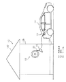
図1は、本発明の第1実施形態に係わる充電装置を備えた建物を示す図である。
(First embodiment)
FIG. 1 is a view showing a building including a charging apparatus according to the first embodiment of the present invention.
図1に示すように、建物12は、基礎12Aと、この基礎12A上に設けられた建物部分12Bと、該建物部分12Bの上に設置された屋根部分12Cと、によって構成されている。なお、上記建物12は、ユニット工法によって構築されたユニット住宅でもよいし、それ以外の軸組工法等による住宅でもよく、更に住宅以外の用途の建物でもよい。
As shown in FIG. 1, the
建物12には、電気自動車やハイブリッド自動車等の自動車14に搭載された蓄電池を充電するための充電装置10が設けられている。充電装置10は、例えば、建物12内に設けられており、建物12に隣接して自動車14を停車し、自動車14に搭載された蓄電池を充電することが可能とされている。建物12内に充電装置10を設けることにより、充電装置10収納部26(図2)等が人為的に損傷されることを防止することができると共に、太陽光の光や熱による劣化も軽減することができる。
The
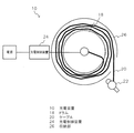
図2は、本発明の第1実施形態に係わる充電装置10の概略構成を示す図である。
FIG. 2 is a diagram showing a schematic configuration of the
充電装置10は、充電のための電力供給を行うケーブル20、及び自動車14と接続するためのプラグ22を備えている。
The
ケーブル20は、ドラム18に巻き取られた状態で収納部26内に収納可能され、充電する際には、収納部26から必要に応じて引き出されて、自動車14の蓄電池と接続するための接続部16とプラグ22とを接続して充電を行うようになっている。
The
また、ケーブル20は、図示しない巻き取りモータを駆動することにより、ドラム18に巻き取ることが可能とされている。
The
ケーブル20が引き出されて、プラグ22が自動車14の接続部16と接続され、充電を開始すると、充電制御装置24によって充電が制御されて自動車14に搭載された蓄電池の充電が行われる。
When the
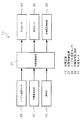
図3は、本発明の第1実施形態に係わる充電装置の制御系の構成を示すブロック図である。 FIG. 3 is a block diagram showing the configuration of the control system of the charging apparatus according to the first embodiment of the present invention.
充電装置10は、図3に示すように、充電制御装置24、充電電流制御部36、ケーブル温度センサ28、充電量検出部30、操作部32、及び巻取モータ34を備えており、充電制御装置24によって充電装置10全体が統括的に制御される。
As shown in FIG. 3, the
充電制御装置24は、充電電流制御部36を制御して自動車14に搭載された蓄電池を充電する際の電流を制御する。
The
ケーブル温度センサ28は、充電装置10のドラム18に巻き取られたケーブル20の温度を測定し、測定結果を充電装置10に出力する。ケーブル温度センサ28は、ドラム18またはケーブル20の表面に熱電対等のセンサを設けるようにしてもよいし、ケーブル20の抵抗変化を検出することにより温度変化を検出するようにしてもよい。
The
充電量検出部30は、プラグ22に接続された自動車14に搭載された蓄電池の充電量が検出され、検出結果が充電制御装置24に出力される。充電制御装置24は、充電量検出部30の検出結果に基づいて充電電流制御部36を制御して充電を行う。例えば、蓄電池の残量が空に近い状態の場合には、定格の最大電流で充電を開始し、充電量が所定値まで達したら電流値を下げて充電する等の制御を行う。
The charge
操作部32は、充電装置10の各種操作を行うための操作ボタンや表示部等を備えている。例えば、操作ボタンとしては、充電を開始するための充電開始ボタンや、充電を強制終了させるための充電終了ボタン、ケーブルをドラム18に巻き取るためのケーブル巻取ボタン等の操作ボタンを備えている。なお、充電開始は、充電開始ボタンの操作によって開始してもよいし、プラグ22が自動車14に接続された時点で開始するようにしてもよい。
The
巻取モータ34は、ドラム18を回転駆動し、ケーブル20をドラム18に巻き取る。例えば、操作部32の操作によってケーブル20の巻き取りが指示された場合には、巻取モータ34を作動してドラム18にケーブル20を巻き取る。また、巻取モータ34の負荷(例えば、電流値等)が所定以上の負荷になったところで充電制御装置24の制御によって巻き取りを停止するようになっている。
The winding
ところで、充電装置10は、自動車14に搭載された蓄電池を充電する際に、ケーブル20がドラム18から全て引き出されずに、ドラム18に巻き取られた状態で充電を開始した場合には、電流がケーブル20を流れることによって発熱する。当該発熱は、ケーブル20の表面の被覆材の材料が樹脂を使用することが多いため、樹脂の劣化等を招くため、好ましくない。
By the way, when charging the storage battery mounted on the
そこで、本実施形態では、充電制御装置24は、ケーブル温度センサ28の検出結果が予め定めた基準値以上の温度の場合には、充電電流制御部36を制御して、充電電流の電流値を下げて充電を行う。すなわち、充電時の電流を下げることによってケーブル20の発熱を抑制してケーブル20を冷却することができる。なお、充電時の電流を下げる際には、予め定めた電流値に下げるようしてもよいし、予め定めた値だけ電流値を下げるようにしてもよい。
Therefore, in the present embodiment, when the detection result of the
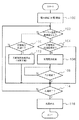
続いて、上述のように構成された本発明の第1実施形態に係わる充電装置10で行われ充電時の処理について説明する。図4は、本発明の第1実施形態に係わる充電装置10の充電制御装置24で行われる処理の流れの一例を示すフローチャートである。
Next, processing at the time of charging performed by the charging
プラグ22が自動車14の接続部16に接続され、充電を行う際には、まず、ステップ100では、充電制御装置24が充電電流制御部36を制御することによって、自動車14に搭載された蓄電池へケーブル20を介して電力供給が開始されてステップ102へ移行する。
When the
ステップ102では、ケーブル温度センサ28の検出結果に基づいて、ケーブル20の温度が予め定めた基準値以上か否かが充電制御装置24によって判定され、該判定が肯定された場合にはステップ104へ移行し、否定された場合にはステップ110へ移行する。
In
ステップ104では、充電電流低減処理中か否かが充電制御装置24によって判定される。該判定は、後段の処理で充電電流を低減する処理が既に行われているか否かを判定し、該判定が否定された場合にはステップ106へ移行し、肯定された場合にはステップ114へ移行する。
In
ステップ106では、充電電流低減処理が行われてステップ108へ移行する。すなわち、充電制御装置24が充電電流制御部36を制御することによって、現在に充電電流より小さい電流値で充電するように制御が行われる。これによって、ケーブル20を流れる電流が減少し、ケーブル20の発熱が抑制される。
In
ステップ108では、5分経過したか否かが充電制御装置24によって判定され、該判定が肯定されるまで待機してステップ110へ移行する。なお、本実施形態では、5分待機するものとして説明するが、5分に限るものではなく、充電電流低減処理による効果が現れる時間を予め定め、当該時間を待機すればよい。
In
一方、ケーブル20の温度が基準値以下と判定され、ステップ110へ移行すると、充電電流低減処理中か否かが充電制御装置24によって判定される。該判定は、上述のステップ106の処理で充電電流を低減する処理が行われているか否かを判定し、該判定が肯定された場合にはステップ112へ移行し、否定された場合にはステップ114へ移行する。
On the other hand, when it is determined that the temperature of the
ステップ112では、充電電流低減処理が停止されて通常の電流値に戻して充電を行うように充電電流制御部36を充電制御装置24が制御してステップ114へ移行する。
In step 112, the charging
ステップ114では、充電終了か否かが充電制御装置24によって判定される。該判定は、例えば、充電量検出部30によって満充電が検出されたか否かを判定したり、操作部32によって充電停止が指示されたか否かを判定し、該判定が否定された場合にはステップ102に戻って上述の処理が繰り返され、判定が肯定された場合にはステップ116へ移行する。
In
ステップ116では、充電制御装置24が充電電流制御部36を制御することによって、充電が停止されて一連の処理を終了する。
In
このように、本実施形態に係わる充電装置10では、ケーブル20が全て引き出されずにドラム18に巻き取られて、ケーブル20の温度が上昇しても、充電電流を下げて充電を行うようにしたので、ケーブル20の発熱を抑制することができ、ケーブル20の熱劣化等を抑制することができる。
As described above, in the charging
(第2実施形態)
続いて、本発明の第2実施形態に係わる充電装置について説明する。図5は、本発明の第2実施形態に係わる充電装置の概略構成を示す図である。なお、第1実施形態と同一構成については同一符号を付して説明する。
(Second Embodiment)
Then, the charging device concerning 2nd Embodiment of this invention is demonstrated. FIG. 5 is a diagram showing a schematic configuration of a charging apparatus according to the second embodiment of the present invention. In addition, about the same structure as 1st Embodiment, the same code | symbol is attached | subjected and demonstrated.
本実施形態における充電装置11についても第1実施形態と同様に、建物12内に設けられて自動車14に搭載された蓄電池を充電する。
Similarly to the first embodiment, the charging
充電装置11は、充電のための電力供給を行うケーブル20、及び自動車14と接続するためのプラグ22を備えている。
The charging
ケーブル20は、ドラム18に巻き取られた状態で収納部26内に収納可能され、充電する際には、収納部26から必要に応じて引き出されて、自動車14の蓄電池と接続するための接続部16とプラグ22とを接続して充電を行うようになっている。
The
また、ケーブル20は、図示しない巻き取りモータを駆動することにより、ドラム18に巻き取ることが可能とされている。
The
ケーブル20が引き出されて、プラグ22が自動車の接続部16と接続され、充電を開始すると、充電制御装置25によって充電電流が制御されて自動車に搭載された蓄電池の充電が行われる。
When the
さらに、本実施形態では、ドラム18内に冷却ファン38が設けられており、ドラム18内からドラム18に巻き取られたケーブル20に向かって冷却風を発生することが可能とされている。すなわち、冷却ファン38を作動することによって、ケーブル20に送風して冷却することが可能とされている。
Furthermore, in this embodiment, a cooling
なお、図5では、複数(4つ)の冷却ファン38を設ける例を示すが、これに限るものではなく、1つでもよいし、4つ以外の複数でもよい。
FIG. 5 shows an example in which a plurality of (four) cooling
図6は、本発明の第2実施形態に係わる充電装置の制御系の構成を示すブロック図である。なお、第1実施形態と同一構成については同一符号を付して説明する。 FIG. 6 is a block diagram showing the configuration of the control system of the charging apparatus according to the second embodiment of the present invention. In addition, about the same structure as 1st Embodiment, the same code | symbol is attached | subjected and demonstrated.
充電装置11は、図6に示すように、充電制御装置25、充電電流制御部36、ケーブル温度センサ28、充電量検出部30、操作部32、巻取モータ34、及び冷却ファン38を備えており、充電制御装置25によって充電装置11全体が統括的に制御される。
As shown in FIG. 6, the charging
充電制御装置25は、充電電流制御部36を制御して自動車14に搭載された蓄電池を充電する際の電流を制御する。
The charging
ケーブル温度センサ28は、充電装置10のドラム18に巻き取られたケーブル20の温度を測定し、測定結果を充電装置10に出力する。ケーブル温度センサ28は、ドラム18またはケーブル20の表面に熱電対等のセンサを設けるようにしてもよいし、ケーブル20の抵抗変化を検出することにより温度変化を検出するようにしてもよい。
The
充電量検出部30は、プラグ22に接続された自動車14に搭載された蓄電池の充電量が検出され、検出結果が充電制御装置25に出力される。充電制御装置25は、充電量検出部30の検出結果に基づいて充電電流制御部36を制御して充電を行う。例えば、蓄電池の残量が空に近い状態の場合には、定格の最大電流で充電を開始し、充電量が所定値まで達したら電流値を下げて充電する等の制御を行う。
The charge
操作部32は、充電装置11の各種操作を行うための操作ボタンや表示部等を備えている。例えば、操作ボタンとしては、充電を開始するための充電開始ボタンや、充電を強制終了させるための充電終了ボタン、ケーブルをドラム18に巻き取るためのケーブル巻取ボタン等の操作ボタンを備えている。なお、充電開始は、充電開始ボタンの操作によって開始してもよいし、プラグ22が自動車14に接続された時点で開始するようにしてもよい。
The
巻取モータ34は、ドラム18を回転駆動し、ケーブル20をドラム18に巻き取る。例えば、操作部32の操作によってケーブル20の巻き取りが指示された場合には、巻取モータ34を作動してドラム18にケーブル20を巻き取る。また、巻取モータ34の負荷(例えば、電流値等)が所定以上の負荷になったところで充電制御装置25の制御によって巻き取りを停止するようになっている。
The winding
また、冷却ファン38は、充電制御装置25の制御によって作動及び停止が制御可能とされており、充電制御装置25は、ケーブル20の温度上昇を抑制するために冷却ファン38の作動を制御するようになっている。
The cooling
充電装置11は、自動車14に搭載された蓄電池を充電する際に、ケーブル20がドラム18から全て引き出されずに、ドラム18に巻き取られた状態で充電を開始した場合には、電流がケーブル20を流れることによって発熱し、第1実施形態で説明したように、当該発熱は、樹脂の劣化等を招くため、好ましくない。
When charging the storage battery mounted on the
そこで、本実施形態では、第1実施形態と同様に、充電電流制御部36を制御して充電電流を低減する処理を行うことによりケーブル20の温度上昇を抑制する機能を備えている。また、本実施形態では、充電電流低減処理を行う前に、冷却ファン38を作動してケーブル20を冷却するようにしている。すなわち、2つの冷却制御を備えて、2つの冷却制御を段階的に行う構成とされている。なお、本実施形態では、2つの冷却制御を段階的に行うものとして説明するが、2つの冷却制御を同時に行うようにしてもよい。
Therefore, in the present embodiment, similarly to the first embodiment, the charging
続いて、上述のように構成された本発明の第2実施形態に係わる充電装置11で行われ充電時の処理について説明する。図7は、本発明の第2実施形態に係わる充電装置11の充電制御装置25で行われる処理の流れの一例を示すフローチャートである。
Next, a process at the time of charging performed by the charging
プラグ22が自動車14の接続部16に接続され、充電を行う際には、まず、ステップ200では、充電制御装置25が充電電流制御部36を制御することによって、自動車14に搭載された蓄電池へケーブル20を介して電力供給が開始されてステップ202へ移行する。
When the
ステップ202では、ケーブル温度センサ28の検出結果に基づいて、ケーブル20の温度が予め定めた基準値以上か否かが充電制御装置25によって判定され、該判定が肯定された場合にはステップ204へ移行し、否定された場合にはステップ218へ移行する。
In
ステップ204では、冷却ファン38が既に後段の処理によって作動されているか否かが充電制御装置25によって判定され、該判定が否定された場合にはステップ206へ移行し、肯定された場合にはステップ212へ移行する。
In
ステップ206では、冷却ファン38が作動されてステップ208へ移行する。すなわち、ケーブル20が基準値以上の温度になった場合には、冷却ファン38が作動されることにより、冷却される。
In
ステップ208では、5分経過したか否かが充電制御装置25によって判定され、該判定が肯定されるまで待機してステップ210へ移行する。なお、本実施形態では、5分待機するものとして説明するが、5分に限るものではなく、冷却ファン38作動による効果が現れる時間を予め定め、当該時間を待機すればよい。
In
ステップ210では、ケーブル温度センサ28の検出結果に基づいて、ケーブル20の温度が予め定めた基準値以上か否かが充電制御装置25によって再び判定され、該判定が肯定された場合にはステップ212へ移行し、否定された場合にはステップ218へ移行する。
In
ステップ212では、充電電流低減処理中か否かが充電制御装置25によって判定される。該判定は、後段の処理で充電電流を低減する処理が既に行われているか否かを判定し、該判定が否定された場合にはステップ214へ移行し、肯定された場合にはステップ222へ移行する。
In
ステップ214では、充電電流低減処理が行われてステップ216へ移行する。すなわち、充電制御装置25が充電電流制御部36を制御することによって、現在に充電電流より小さい電流値で充電するように制御が行われる。これによって、ケーブル20を流れる電流が減少し、ケーブル20の発熱が抑制される。
In
ステップ216では、5分経過したか否かが充電制御装置25によって判定され、該判定が肯定されるまで待機してステップ222へ移行する。なお、本実施形態では、5分待機するものとして説明するが、5分に限るものではなく、充電電流低減処理による効果が現れる時間を予め定め、当該時間を待機すればよい。
In
一方、ステップ202において、ケーブル20の温度が基準値以下と判定され、ステップ218へ移行すると、温度低下処理中か否かが充電制御装置25によって判定される。該判定は、上述のステップ206やステップ214によってケーブル20の温度を低下させる処理が行われているか否かを判定し、該判定が肯定された場合にはステップ220へ移行し、否定された場合にはステップ222へ移行する。
On the other hand, in
ステップ220では、温度低下処理が停止されてステップ222へ移行する。すなわち、冷却ファン38が作動している場合には、充電制御装置25の制御によって、冷却ファン38が停止され、充電電流を低下させる処理が行われている場合には、充電制御装置25の制御によって充電電流低減処理が停止されて通常の電流値に戻して充電を行うように制御される。
In
ステップ222では、充電終了か否かが充電制御装置25によって判定される。該判定は、例えば、充電量検出部30によって満充電が検出されたか否かを判定したり、操作部32によって充電停止が指示されたか否かを判定し、該判定が否定された場合にはステップ202に戻って上述の処理が繰り返され、判定が肯定された場合にはステップ224へ移行する。
In
ステップ224では、充電制御装置25が充電電流制御部36を制御することによって、充電が停止されて一連の処理を終了する。
In
このように、本実施形態に係わる充電装置11では、ケーブル20が全て引き出されずにドラム18に巻き取られて、ケーブル20の温度が上昇しても、基準値以上の温度になった場合には冷却ファン38を作動して冷却し、それでも冷却しきれない場合には、第1実施形態と同様に、充電電流を低下させるように制御するので、ケーブル20の発熱を抑制することができ、ケーブル20の熱劣化等を抑制することができる。
As described above, in the charging
また、充電電流低下処理よりも冷却ファン38の作動を優先するようにしたことにより、充電電流が下がることによって充電時間が長くなってしまう弊害を抑制することができる。
In addition, since the operation of the cooling
なお、第2実施形態では、冷却ファン38によるケーブル20の冷却と、充電電流の低下によるケーブル20の冷却とを段階的に行うようにしたが、同時に行うようにしてもよい。
In the second embodiment, the cooling of the
(第3実施形態)
続いて、本発明の第3実施形態に係わる充電装置について説明する。図8は、本発明の第3実施形態に係わる充電装置の概略構成を示す図である。なお、第1実施形態と同一構成については同一符号を付して説明する。
(Third embodiment)
Then, the charging device concerning 3rd Embodiment of this invention is demonstrated. FIG. 8 is a diagram showing a schematic configuration of a charging apparatus according to the third embodiment of the present invention. In addition, about the same structure as 1st Embodiment, the same code | symbol is attached | subjected and demonstrated.
本実施形態における充電装置13についても第1実施形態と同様に、建物12内に設けられて自動車14に搭載された蓄電池を充電する。
Similarly to the first embodiment, the charging
充電装置13は、充電のための電力供給を行うケーブル20、及び自動車14と接続するためのプラグ22を備えている。
The charging
ケーブル20は、ドラム18に巻き取られた状態で収納部26内に収納可能され、充電する際には、収納部26から必要に応じて引き出されて、自動車14の蓄電池と接続するための接続部16とプラグ22とを接続して充電を行うようになっている。
The
また、ケーブル20は、図示しない巻き取りモータを駆動することにより、ドラム18に巻き取ることが可能とされている。
The
ケーブル20が引き出されて、プラグ22が自動車の接続部16と接続され、充電を開始すると、充電制御装置27によって充電電流が制御されて自動車に搭載された蓄電池の充電が行われる。
When the
さらに、本実施形態では、ケーブル20を強制的に引き出す引出装置40が設けられている。
Further, in the present embodiment, a
引出装置40は、一対のローラ42を有して、ローラ42を回転させることによって、ドラム18に巻き取られたケーブル20を引き出すことが可能とされている。本実施形態では、ケーブル20を引出装置40によって強制的に全て引き出すことによってドラム18内で発熱してしまうことを防止することができるようにしている。
The
図9は、本発明の第3実施形態に係わる充電装置13の制御系の構成を示すブロック図である。なお、第1実施形態と同一構成については同一符号を付して説明する。
FIG. 9 is a block diagram showing the configuration of the control system of the charging
充電装置13は、図9に示すように、充電制御装置27、充電電流制御部36、ケーブル温度センサ28、充電量検出部30、操作部32、巻取モータ34、及び引出モータ44を備えており、充電制御装置27によって充電装置13全体が統括的に制御される。
As shown in FIG. 9, the charging
充電制御装置27は、充電電流制御部36を制御して自動車14に搭載された蓄電池を充電する際の電流を制御する。
The charging
ケーブル温度センサ28は、充電装置10のドラム18に巻き取られたケーブル20の温度を測定し、測定結果を充電装置10に出力する。ケーブル温度センサ28は、ドラム18またはケーブル20の表面に熱電対等のセンサを設けるようにしてもよいし、ケーブル20の抵抗変化を検出することにより温度変化を検出するようにしてもよい。
The
充電量検出部30は、プラグ22に接続された自動車14に搭載された蓄電池の充電量が検出され、検出結果が充電制御装置27に出力される。充電制御装置27は、充電量検出部30の検出結果に基づいて充電電流制御部36を制御して充電を行う。例えば、蓄電池の残量が空に近い状態の場合には、定格の最大電流で充電を開始し、充電量が所定値まで達したら電流値を下げて充電する等の制御を行う。
The charge
操作部32は、充電装置13の各種操作を行うための操作ボタンや表示部等を備えている。例えば、操作ボタンとしては、充電を開始するための充電開始ボタンや、充電を強制終了させるための充電終了ボタン、ケーブルをドラム18に巻き取るためのケーブル巻取ボタン等の操作ボタンを備えている。なお、充電開始は、充電開始ボタンの操作によって開始してもよいし、プラグ22が自動車14に接続された時点で開始するようにしてもよい。
The
巻取モータ34は、ドラム18を回転駆動し、ケーブル20をドラム18に巻き取る。例えば、操作部32の操作によってケーブル20の巻き取りが指示された場合には、巻取モータ34を作動してドラム18にケーブル20を巻き取る。また、巻取モータ34の負荷(例えば、電流値等)が所定以上の負荷になったところで充電制御装置27の制御によって巻き取りを停止するようになっている。
The winding
また、引出モータ44は、上述の引出装置40の一対のローラ42を駆動する。本実施形態ででは、引出モータ44は、ドラム18に巻き取られたケーブル20を引き出す方向に一対のローラ42を駆動する。これによってドラム18に巻き取れたケーブル20を強制的に引き出すことができる。なお、引出モータ44が駆動された場合には、所定の負荷(例えば、引出モータ44を駆動する電流値が所定値以上)が検出された場合には、ケーブル20が全て引き出されたものとして停止する。
The drawing
充電装置13は、自動車14に搭載された蓄電池を充電する際に、ケーブル20がドラム18から全て引き出されずに、ドラム18に巻き取られた状態で充電を開始した場合には、電流がケーブル20を流れることによって発熱し、第1実施形態で説明したように、当該発熱は、樹脂の劣化等を招くため、好ましくない。
When charging the storage battery mounted on the
そこで、本実施形態では、第1実施形態と同様に、充電電流制御部36を制御して充電電流を低減する処理を行うことによりケーブル20の温度上昇を抑制する機能を備えている。また、本実施形態では、充電電流低減処理を行う前に、ドラム18に巻き取られているケーブル20を引出装置40によって強制的に引き出して放熱しやすくするようにしている。すなわち、2つの冷却制御を備えて、2つの冷却制御を段階的に行う構成とされている。なお、本実施形態では、2つの冷却制御を段階的に行うものとして説明するが、2つの冷却制御を同時に行うようにしてもよい。
Therefore, in the present embodiment, similarly to the first embodiment, the charging
続いて、上述のように構成された本発明の第3実施形態に係わる充電装置13で行われ充電時の処理について説明する。図10は、本発明の第3実施形態に係わる充電装置13の充電制御装置27で行われる処理の流れの一例を示すフローチャートである。なお、第2実施形態と共通処理が多いため、第2実施形態と同一処理については同一符号を付して説明する。
Next, the charging process performed by the charging
プラグ22が自動車14の接続部16に接続され、充電を行う際には、まず、ステップ200では、充電制御装置27が充電電流制御部36を制御することによって、自動車14に搭載された蓄電池へケーブル20を介して電力供給が開始されてステップ202へ移行する。
When the
ステップ202では、ケーブル温度センサ28の検出結果に基づいて、ケーブル20の温度が予め定めた基準値以上か否かが充電制御装置27によって判定され、該判定が肯定された場合にはステップ205へ移行し、否定された場合にはステップ218へ移行する。
In
ステップ205では、後段の処理によって引出装置40が作動されてケーブル20が既に引き出されているか否かが充電制御装置27によって判定され、該判定が否定された場合にはステップ207へ移行し、肯定された場合にはステップ212へ移行する。
In
ステップ207では、充電制御装置27によって引出モータ44が制御されて引出装置40の一対のローラ42が駆動されることにより、ドラム18に巻き取られたケーブル20が強制的に引き出されてステップ208へ移行する。すなわち、ケーブル20が基準値以上の温度になった場合には、ドラム18に巻き取られたケーブル20が強制的に引き出されることによって、放熱し易くなり、冷却される。
In
ステップ208では、5分経過したか否かが充電制御装置27によって判定され、該判定が肯定されるまで待機してステップ210へ移行する。なお、本実施形態では、5分待機するものとして説明するが、5分に限るものではなく、冷却ファン38作動による効果が現れる時間を予め定め、当該時間を待機すればよい。
In
ステップ210では、ケーブル温度センサ28の検出結果に基づいて、ケーブル20の温度が予め定めた基準値以上か否かが充電制御装置27によって再び判定され、該判定が肯定された場合にはステップ212へ移行し、否定された場合にはステップ218へ移行する。
In
ステップ212では、充電電流低減処理中か否かが充電制御装置27によって判定される。該判定は、後段の処理で充電電流を低減する処理が既に行われているか否かを判定し、該判定が否定された場合にはステップ214へ移行し、肯定された場合にはステップ222へ移行する。
In
ステップ214では、充電電流低減処理が行われてステップ216へ移行する。すなわち、充電制御装置27が充電電流制御部36を制御することによって、現在に充電電流より小さい電流値で充電するように制御が行われる。これによって、ケーブル20を流れる電流が減少し、ケーブル20の発熱が抑制される。
In
ステップ216では、5分経過したか否かが充電制御装置27によって判定され、該判定が肯定されるまで待機してステップ222へ移行する。なお、本実施形態では、5分待機するものとして説明するが、5分に限るものではなく、充電電流低減処理による効果が現れる時間を予め定め、当該時間を待機すればよい。
In
一方、ステップ202において、ケーブル20の温度が基準値以下と判定され、ステップ218へ移行すると、温度低下処理中か否かが充電制御装置27によって判定される。該判定は、上述のステップ207やステップ214によってケーブル20の温度を低下させる処理が行われているか否かを判定し、該判定が肯定された場合にはステップ220へ移行し、否定された場合にはステップ222へ移行する。
On the other hand, in
ステップ220では、温度低下処理が停止されてステップ222へ移行する。すなわち、ケーブル20が強制的に引き出されている場合には、引出装置40によって引き出した分だけ巻き取るように巻取モータ34を作動してドラム18にケーブル20を巻き取り、充電電流を低下させる処理が行われている場合には、充電制御装置27の制御によって充電電流低減処理が停止されて通常の電流値に戻して充電を行うように制御される。なお、ケーブル20が引出装置40によって強制的に引き出されている場合にはそのまま引き出されたままとしてもよい。
In
ステップ222では、充電終了か否かが充電制御装置27によって判定される。該判定は、例えば、充電量検出部30によって満充電が検出されたか否かを判定したり、操作部32によって充電停止が指示されたか否かを判定し、該判定が否定された場合にはステップ202に戻って上述の処理が繰り返され、判定が肯定された場合にはステップ224へ移行する。
In
ステップ224では、充電制御装置27が充電電流制御部36を制御することによって、充電が停止されて一連の処理を終了する。
In
このように、本実施形態に係わる充電装置13では、ケーブル20が全て引き出されずにドラム18に巻き取られて、ケーブル20の温度が上昇しても、基準値以上の温度になった場合には引出装置40によって強制的にケーブル20をドラム18から引き出して冷却し、それでも冷却しきれない場合には、第1実施形態と同様に、充電電流を低下させるように制御するので、ケーブル20の発熱を抑制することができ、ケーブル20の熱劣化等を抑制することができる。
As described above, in the charging
また、充電電流低下処理よりも引出装置40によるケーブル20の引き出し動作を優先するようにしたことにより、充電電流が下がることによって充電時間が長くなってしまう弊害を抑制することができる。
In addition, since the drawing operation of the
なお、第3実施形態では、引出装置40のケーブル20の引き出しによる冷却と、充電電流の低下によるケーブル20の冷却とを段階的に行うようにしたが、同時に行うようにしてもよい。
In the third embodiment, the cooling by pulling out the
また、上記の各実施形態におけるケーブル20を冷却するための構成は、適宜備えて段階的に制御するようにしてもよい。すなわち、充電電流低下によるケーブル20の冷却、冷却ファン38による冷却、及び引出装置40によるケーブル20の引き出しによる冷却のうち少なくとも1つの冷却方法を備えて、段階的に冷却を行うようにしてもよい。
The configuration for cooling the
また、上記の各実施形態では、ケーブル20を冷却する方法として、充電電流低下による冷却、冷却ファンによる冷却、及び引出装置40によるケーブル20の引き出しによる冷却を一例として挙げて説明したが、これに限るものではなく、他の冷却手段を適用するようにしてもよい。例えば、水冷でケーブル20を冷却する等の冷却手段を適用するようにしてもよい。
In each of the above embodiments, the method of cooling the
また、上記の各実施形態では、ケーブル20の温度を監視して、冷却制御を行う例を説明したが、これに限るものではなく、ケーブル20の温度の代わりに、充電電流制御部36によって充電電流を監視して充電電流が所定値以上に上昇した場合に、ケーブル20の温度が上昇する可能性が高いので、充電電流低下による冷却や、冷却ファン38による冷却、引出装置40によるケーブル20の引き出しによる冷却等のケーブル20を冷却するための処理を実行するようにしてもよい。
Further, in each of the above embodiments, the example in which the temperature of the
また、第2実施形態及び第3実施形態では、ケーブル20の温度が基準値以上の場合にケーブル20を冷却するように制御した後に、予め定めた基準温度以下にならない場合、すなわちケーブル20の冷却が不十分な場合に、充電電流を低下する処理を行うようにしたが、冷却が不十分な場合の定義づけとしては、予め定めた基準温度以下にならない場合の他に、温度の低下速度が予め定めた速度より遅い場合や、温度が下がらない場合(温度が上昇する場合を含む)等を適用することができるが、本発明の趣旨を逸脱しない範囲で適宜変更可能である。また、温度の低下速度が予め定めた速度より遅いか否かの判断は、予め定めた高温状態と予め定めた低温状態とで異なるようにしてもよい。高温状態>低温状態として、ケーブル20の冷却が不十分な場合の定義付けとして、温度の低下速度が高温状態の方が速いことを基準として設定してもよい。また、ケーブル20の温度が基準値以上という設定も、変更できるように手動、又は自動で設定できるようにしてもよい。この場合には、例えば、ケーブル20の温度が基準値以上の高温状態を高い温度で設定する場合は充電電流低下による充電時間の過度な延長を抑制できる。また、上記ケーブル20の温度の基準値も季節に応じて変更できるように、例えば、夏場は低く、冬場は高く手動、又は自動で変更できるように設定してもよい。
Further, in the second embodiment and the third embodiment, when the
また、第2実施形態及び第3実施形態におけるステップ208とステップ216の時間は、異なる時間に設定してもよい。例えば、ステップ216の方が、ステップ208より時間が短くなるように設定してもよい。そうすることで、段階的に冷却を行う場合に2段目以降の冷却手段を不必要に長時間作動させることを低減でき、ステップ214の場合のように、充電電流を低下させる処理を2段目以降の冷却手段として適用する場合には、充電時間の過度な延長を抑制することができる。
Moreover, you may set the time of
その他、前記段階的に冷却手段を作動させて、その後、所定の時間経過(例えば、冷却手段による冷却を開始して合計の時間でもよいし、2段目以降の冷却手段による冷却を開始した特定時間でもよい。)しても、冷却が不十分と判断された場合には、充電装置による充電を継続せずに緊急停止するようにしてもよいし、或いは、冷却されるまで充電を一旦停止した後に冷却後に充電を再開するようにしてもよい。 In addition, the cooling means is actuated stepwise, and then a predetermined time has elapsed (for example, the cooling means may start cooling and the total time may be used, or the cooling by the second and subsequent cooling means may be specified) However, if it is determined that the cooling is insufficient, the charging may be stopped without continuing the charging by the charging device, or the charging is temporarily stopped until the cooling is performed. Then, after cooling, charging may be resumed.
10、11、13 充電装置
12 建物
18 ドラム
20 ケーブル
24、25、27 充電制御装置
26 収納部
28 ケーブル温度センサ
36 充電電流制御部
38 冷却ファン
40 引出装置
44 引出モータ
DESCRIPTION OF
Claims (8)
前記収納手段に巻き取られた前記充電ケーブルの温度、または蓄電池の充電電流を検出する検出手段と、
蓄電池を充電する際に充電電流を制御する充電電流制御手段と、
前記検出手段の検出結果に基づいて、前記充電ケーブルが発熱している可能性がある場合に、充電電流を低下するように前記充電電流制御手段を制御する制御手段と、
を備えた充電装置。 Storage means for winding and storing a charging cable used when charging the storage battery; and
Detecting means for detecting the temperature of the charging cable wound around the storage means or the charging current of the storage battery;
Charging current control means for controlling the charging current when charging the storage battery;
Control means for controlling the charging current control means so as to reduce the charging current when there is a possibility that the charging cable is generating heat based on the detection result of the detecting means;
A charging device.
前記収納手段に巻き取られた前記充電ケーブルの温度、または蓄電池の充電電流を検出する検出手段と、
前記充電ケーブルを冷却する複数種類の冷却手段と、
前記検出手段の検出結果に基づいて、前記充電ケーブルが発熱している可能性がある場合に、前記複数の冷却手段を段階的に作動するように前記複数の冷却手段を制御する制御手段と、
を備えた充電装置。 Storage means for winding and storing a charging cable used when charging the storage battery; and
Detecting means for detecting the temperature of the charging cable wound around the storage means or the charging current of the storage battery;
A plurality of types of cooling means for cooling the charging cable;
Control means for controlling the plurality of cooling means so as to operate the plurality of cooling means stepwise when there is a possibility that the charging cable is generating heat based on the detection result of the detection means;
A charging device.
Priority Applications (1)
| Application Number | Priority Date | Filing Date | Title |
|---|---|---|---|
| JP2011006179A JP5743562B2 (en) | 2011-01-14 | 2011-01-14 | Charger |
Applications Claiming Priority (1)
| Application Number | Priority Date | Filing Date | Title |
|---|---|---|---|
| JP2011006179A JP5743562B2 (en) | 2011-01-14 | 2011-01-14 | Charger |
Publications (2)
| Publication Number | Publication Date |
|---|---|
| JP2012147642A true JP2012147642A (en) | 2012-08-02 |
| JP5743562B2 JP5743562B2 (en) | 2015-07-01 |
Family
ID=46790611
Family Applications (1)
| Application Number | Title | Priority Date | Filing Date |
|---|---|---|---|
| JP2011006179A Active JP5743562B2 (en) | 2011-01-14 | 2011-01-14 | Charger |
Country Status (1)
| Country | Link |
|---|---|
| JP (1) | JP5743562B2 (en) |
Cited By (9)
| Publication number | Priority date | Publication date | Assignee | Title |
|---|---|---|---|---|
| JP2012196120A (en) * | 2011-03-03 | 2012-10-11 | Panasonic Corp | Charge cable for electric propulsion vehicle |
| US8981731B1 (en) | 2013-10-24 | 2015-03-17 | Panasonic Intellectual Property Corporation Of America | Charger and electronic apparatus system |
| JP2015089337A (en) * | 2013-10-31 | 2015-05-07 | 本田技研工業株式会社 | Methods and systems for charging electric vehicle |
| US9071058B2 (en) | 2013-07-19 | 2015-06-30 | Panasonic Intellectual Property Corporation Of America | Charger and electronic apparatus system |
| CN104953639A (en) * | 2014-03-31 | 2015-09-30 | 深圳市浪尖设计有限公司 | Automatic charging pile |
| EP3257701A3 (en) * | 2016-06-15 | 2017-12-27 | Dr. Ing. h.c. F. Porsche AG | Loading device for an energy storage device of an electric vehicle |
| JP2019140827A (en) * | 2018-02-13 | 2019-08-22 | トヨタ自動車株式会社 | Vehicle power control device |
| CN112644319A (en) * | 2020-12-23 | 2021-04-13 | 襄阳弗洛达科技有限公司 | Temperature control system based on household car charging detection |
| EP4207543A1 (en) * | 2021-12-31 | 2023-07-05 | VOITAS Innovations GmbH | Charging device for charging electrical energy storages |
Families Citing this family (2)
| Publication number | Priority date | Publication date | Assignee | Title |
|---|---|---|---|---|
| CN107139759B (en) * | 2017-05-28 | 2018-06-19 | 南通欧贝黎新能源电力股份有限公司 | A kind of solar recharging stake device |
| CN110239378B (en) * | 2019-07-04 | 2022-03-25 | 广州顺充新能源有限公司 | Control method for self-adaptive current output of alternating current charging pile |
Citations (14)
| Publication number | Priority date | Publication date | Assignee | Title |
|---|---|---|---|---|
| JPH0196478U (en) * | 1987-12-18 | 1989-06-27 | ||
| JPH0883640A (en) * | 1994-09-13 | 1996-03-26 | Osami Watanabe | Cord reel device with fire preventing switch mechanism |
| JPH08119540A (en) * | 1994-10-28 | 1996-05-14 | Matsushita Electric Ind Co Ltd | Cord reel device with outlet part |
| JPH1174001A (en) * | 1997-09-01 | 1999-03-16 | Shin Kobe Electric Mach Co Ltd | Charging method for lead-acid battery |
| JP2000115915A (en) * | 1998-09-30 | 2000-04-21 | Harness Syst Tech Res Ltd | Connector device for electric vehicle charging |
| JP2003244832A (en) * | 2002-02-15 | 2003-08-29 | Mitsubishi Motors Corp | Electric automobile |
| JP2004303629A (en) * | 2003-03-31 | 2004-10-28 | Daiwa House Ind Co Ltd | Structure of embedded type outlet |
| JP2008252986A (en) * | 2007-03-29 | 2008-10-16 | Toyota Motor Corp | Charging cable and charging system |
| JP2008545601A (en) * | 2005-05-31 | 2008-12-18 | グレート スタッフ インコーポレイテッド | Improved reel and reel housing |
| WO2009091745A2 (en) * | 2008-01-14 | 2009-07-23 | Aerovironment | Sliding conductor transmission cable |
| JP2010052861A (en) * | 2008-08-26 | 2010-03-11 | Panasonic Electric Works Co Ltd | Code set for charging electric vehicle |
| US20100084500A1 (en) * | 2008-10-03 | 2010-04-08 | Inman Anthony D | Cord reel |
| JP2010110055A (en) * | 2008-10-28 | 2010-05-13 | Panasonic Electric Works Co Ltd | Charging cable for electric vehicle |
| JP2010110051A (en) * | 2008-10-28 | 2010-05-13 | Panasonic Electric Works Co Ltd | Charging system |
-
2011
- 2011-01-14 JP JP2011006179A patent/JP5743562B2/en active Active
Patent Citations (15)
| Publication number | Priority date | Publication date | Assignee | Title |
|---|---|---|---|---|
| JPH0196478U (en) * | 1987-12-18 | 1989-06-27 | ||
| JPH0883640A (en) * | 1994-09-13 | 1996-03-26 | Osami Watanabe | Cord reel device with fire preventing switch mechanism |
| JPH08119540A (en) * | 1994-10-28 | 1996-05-14 | Matsushita Electric Ind Co Ltd | Cord reel device with outlet part |
| JPH1174001A (en) * | 1997-09-01 | 1999-03-16 | Shin Kobe Electric Mach Co Ltd | Charging method for lead-acid battery |
| JP2000115915A (en) * | 1998-09-30 | 2000-04-21 | Harness Syst Tech Res Ltd | Connector device for electric vehicle charging |
| JP2003244832A (en) * | 2002-02-15 | 2003-08-29 | Mitsubishi Motors Corp | Electric automobile |
| JP2004303629A (en) * | 2003-03-31 | 2004-10-28 | Daiwa House Ind Co Ltd | Structure of embedded type outlet |
| JP2008545601A (en) * | 2005-05-31 | 2008-12-18 | グレート スタッフ インコーポレイテッド | Improved reel and reel housing |
| JP2008252986A (en) * | 2007-03-29 | 2008-10-16 | Toyota Motor Corp | Charging cable and charging system |
| WO2009091745A2 (en) * | 2008-01-14 | 2009-07-23 | Aerovironment | Sliding conductor transmission cable |
| JP2011510602A (en) * | 2008-01-14 | 2011-03-31 | エアロバイロメント | Sliding conductor power transmission cable |
| JP2010052861A (en) * | 2008-08-26 | 2010-03-11 | Panasonic Electric Works Co Ltd | Code set for charging electric vehicle |
| US20100084500A1 (en) * | 2008-10-03 | 2010-04-08 | Inman Anthony D | Cord reel |
| JP2010110055A (en) * | 2008-10-28 | 2010-05-13 | Panasonic Electric Works Co Ltd | Charging cable for electric vehicle |
| JP2010110051A (en) * | 2008-10-28 | 2010-05-13 | Panasonic Electric Works Co Ltd | Charging system |
Cited By (11)
| Publication number | Priority date | Publication date | Assignee | Title |
|---|---|---|---|---|
| JP2012196120A (en) * | 2011-03-03 | 2012-10-11 | Panasonic Corp | Charge cable for electric propulsion vehicle |
| US9071058B2 (en) | 2013-07-19 | 2015-06-30 | Panasonic Intellectual Property Corporation Of America | Charger and electronic apparatus system |
| US8981731B1 (en) | 2013-10-24 | 2015-03-17 | Panasonic Intellectual Property Corporation Of America | Charger and electronic apparatus system |
| US9407101B2 (en) | 2013-10-24 | 2016-08-02 | Panasonic Intellectual Property Corporation Of America | Charger and electronic apparatus system |
| JP2015089337A (en) * | 2013-10-31 | 2015-05-07 | 本田技研工業株式会社 | Methods and systems for charging electric vehicle |
| CN104953639A (en) * | 2014-03-31 | 2015-09-30 | 深圳市浪尖设计有限公司 | Automatic charging pile |
| EP3257701A3 (en) * | 2016-06-15 | 2017-12-27 | Dr. Ing. h.c. F. Porsche AG | Loading device for an energy storage device of an electric vehicle |
| JP2019140827A (en) * | 2018-02-13 | 2019-08-22 | トヨタ自動車株式会社 | Vehicle power control device |
| JP6992567B2 (en) | 2018-02-13 | 2022-01-13 | トヨタ自動車株式会社 | Vehicle power control device |
| CN112644319A (en) * | 2020-12-23 | 2021-04-13 | 襄阳弗洛达科技有限公司 | Temperature control system based on household car charging detection |
| EP4207543A1 (en) * | 2021-12-31 | 2023-07-05 | VOITAS Innovations GmbH | Charging device for charging electrical energy storages |
Also Published As
| Publication number | Publication date |
|---|---|
| JP5743562B2 (en) | 2015-07-01 |
Similar Documents
| Publication | Publication Date | Title |
|---|---|---|
| JP5743562B2 (en) | Charger | |
| KR101679927B1 (en) | System for cooling in electric vehicle and method thereof | |
| KR101455550B1 (en) | Charge control apparatus for vehicle | |
| US9473002B2 (en) | System and method for cooling dynamoelectric machine | |
| KR101947464B1 (en) | Marine hybrid generator and power control method of the same | |
| JP2007537110A (en) | Improved energy storage method for hoisting machinery | |
| JP2006244829A (en) | Temperature control device and power source device | |
| JP2013031282A (en) | Rotary electric machine | |
| JP2001240323A (en) | Control device of elevator | |
| JP2007323810A (en) | Secondary battery temperature regulator | |
| JP6642391B2 (en) | Drive control device | |
| JP6631493B2 (en) | In-vehicle battery pack cooling system | |
| JP2018137220A (en) | Fuel cell control device, control method thereof, and fuel cell vehicle | |
| US7514892B2 (en) | Method and a control system for starting a motor for driving a compressor | |
| JP2013216173A (en) | Cooling fan control device | |
| CN105471016A (en) | Method for charging the starter battery of a vehicle | |
| JP2010058635A (en) | Battery cooling device | |
| JP2015156765A (en) | Electric vehicle and electric vehicle battery heating method | |
| JP2008099443A (en) | Battery monitor | |
| JP2020182298A (en) | Charging cable with winding device | |
| KR101725597B1 (en) | Secondary Battery Charging And Discharging System And Control Method For Cooling | |
| JP2016110912A (en) | Power storage system, power management device, and temperature management method | |
| JP2006296304A (en) | Ventilating system of gardening house and ventilation-controlling method | |
| JP6772583B2 (en) | Electric vehicle | |
| JPH08186901A (en) | Ventilating fan controller |
Legal Events
| Date | Code | Title | Description |
|---|---|---|---|
| A621 | Written request for application examination |
Free format text: JAPANESE INTERMEDIATE CODE: A621 Effective date: 20131225 |
|
| A711 | Notification of change in applicant |
Free format text: JAPANESE INTERMEDIATE CODE: A711 Effective date: 20131225 |
|
| A521 | Request for written amendment filed |
Free format text: JAPANESE INTERMEDIATE CODE: A821 Effective date: 20131225 |
|
| A977 | Report on retrieval |
Free format text: JAPANESE INTERMEDIATE CODE: A971007 Effective date: 20140829 |
|
| A131 | Notification of reasons for refusal |
Free format text: JAPANESE INTERMEDIATE CODE: A131 Effective date: 20140909 |
|
| A521 | Request for written amendment filed |
Free format text: JAPANESE INTERMEDIATE CODE: A523 Effective date: 20141104 |
|
| TRDD | Decision of grant or rejection written | ||
| A01 | Written decision to grant a patent or to grant a registration (utility model) |
Free format text: JAPANESE INTERMEDIATE CODE: A01 Effective date: 20150414 |
|
| A61 | First payment of annual fees (during grant procedure) |
Free format text: JAPANESE INTERMEDIATE CODE: A61 Effective date: 20150428 |
|
| R150 | Certificate of patent or registration of utility model |
Ref document number: 5743562 Country of ref document: JP Free format text: JAPANESE INTERMEDIATE CODE: R150 |
|
| R250 | Receipt of annual fees |
Free format text: JAPANESE INTERMEDIATE CODE: R250 |
|
| R250 | Receipt of annual fees |
Free format text: JAPANESE INTERMEDIATE CODE: R250 |
|
| R250 | Receipt of annual fees |
Free format text: JAPANESE INTERMEDIATE CODE: R250 |
|
| R250 | Receipt of annual fees |
Free format text: JAPANESE INTERMEDIATE CODE: R250 |