JP2012142804A - Display control program, display controller, display control method, and display control system - Google Patents
Display control program, display controller, display control method, and display control system Download PDFInfo
- Publication number
- JP2012142804A JP2012142804A JP2010294536A JP2010294536A JP2012142804A JP 2012142804 A JP2012142804 A JP 2012142804A JP 2010294536 A JP2010294536 A JP 2010294536A JP 2010294536 A JP2010294536 A JP 2010294536A JP 2012142804 A JP2012142804 A JP 2012142804A
- Authority
- JP
- Japan
- Prior art keywords
- virtual camera
- virtual
- display control
- view
- stereoscopic
- Prior art date
- Legal status (The legal status is an assumption and is not a legal conclusion. Google has not performed a legal analysis and makes no representation as to the accuracy of the status listed.)
- Granted
Links
- 238000000034 method Methods 0.000 title claims abstract description 29
- 238000003384 imaging method Methods 0.000 claims description 35
- 238000009877 rendering Methods 0.000 claims description 6
- 239000007787 solid Substances 0.000 abstract 1
- 230000010365 information processing Effects 0.000 description 44
- 238000004891 communication Methods 0.000 description 19
- 230000001133 acceleration Effects 0.000 description 16
- 238000013500 data storage Methods 0.000 description 16
- 230000008859 change Effects 0.000 description 12
- 238000012545 processing Methods 0.000 description 11
- 230000000694 effects Effects 0.000 description 10
- 230000006870 function Effects 0.000 description 10
- 230000008569 process Effects 0.000 description 10
- 230000004888 barrier function Effects 0.000 description 9
- 238000010586 diagram Methods 0.000 description 5
- 238000003780 insertion Methods 0.000 description 5
- 230000037431 insertion Effects 0.000 description 5
- 238000004364 calculation method Methods 0.000 description 4
- 238000005401 electroluminescence Methods 0.000 description 4
- 239000004973 liquid crystal related substance Substances 0.000 description 3
- 230000004044 response Effects 0.000 description 3
- 238000006243 chemical reaction Methods 0.000 description 2
- 230000007246 mechanism Effects 0.000 description 2
- 238000013459 approach Methods 0.000 description 1
- 230000003247 decreasing effect Effects 0.000 description 1
- 238000001514 detection method Methods 0.000 description 1
- 239000011521 glass Substances 0.000 description 1
- 230000006872 improvement Effects 0.000 description 1
- 230000004048 modification Effects 0.000 description 1
- 238000012986 modification Methods 0.000 description 1
- 239000004065 semiconductor Substances 0.000 description 1
- 230000005236 sound signal Effects 0.000 description 1
- 230000007480 spreading Effects 0.000 description 1
- 230000002194 synthesizing effect Effects 0.000 description 1
- 230000000007 visual effect Effects 0.000 description 1
Images


Classifications
-
- A—HUMAN NECESSITIES
- A63—SPORTS; GAMES; AMUSEMENTS
- A63F—CARD, BOARD, OR ROULETTE GAMES; INDOOR GAMES USING SMALL MOVING PLAYING BODIES; VIDEO GAMES; GAMES NOT OTHERWISE PROVIDED FOR
- A63F13/00—Video games, i.e. games using an electronically generated display having two or more dimensions
- A63F13/50—Controlling the output signals based on the game progress
- A63F13/52—Controlling the output signals based on the game progress involving aspects of the displayed game scene
- A63F13/525—Changing parameters of virtual cameras
- A63F13/5252—Changing parameters of virtual cameras using two or more virtual cameras concurrently or sequentially, e.g. automatically switching between fixed virtual cameras when a character changes room or displaying a rear-mirror view in a car-driving game
-
- H—ELECTRICITY
- H04—ELECTRIC COMMUNICATION TECHNIQUE
- H04N—PICTORIAL COMMUNICATION, e.g. TELEVISION
- H04N13/00—Stereoscopic video systems; Multi-view video systems; Details thereof
- H04N13/10—Processing, recording or transmission of stereoscopic or multi-view image signals
- H04N13/106—Processing image signals
- H04N13/128—Adjusting depth or disparity
-
- H—ELECTRICITY
- H04—ELECTRIC COMMUNICATION TECHNIQUE
- H04N—PICTORIAL COMMUNICATION, e.g. TELEVISION
- H04N13/00—Stereoscopic video systems; Multi-view video systems; Details thereof
- H04N13/20—Image signal generators
- H04N13/275—Image signal generators from 3D object models, e.g. computer-generated stereoscopic image signals
-
- H—ELECTRICITY
- H04—ELECTRIC COMMUNICATION TECHNIQUE
- H04N—PICTORIAL COMMUNICATION, e.g. TELEVISION
- H04N13/00—Stereoscopic video systems; Multi-view video systems; Details thereof
- H04N13/30—Image reproducers
- H04N13/356—Image reproducers having separate monoscopic and stereoscopic modes
- H04N13/359—Switching between monoscopic and stereoscopic modes
-
- A—HUMAN NECESSITIES
- A63—SPORTS; GAMES; AMUSEMENTS
- A63F—CARD, BOARD, OR ROULETTE GAMES; INDOOR GAMES USING SMALL MOVING PLAYING BODIES; VIDEO GAMES; GAMES NOT OTHERWISE PROVIDED FOR
- A63F13/00—Video games, i.e. games using an electronically generated display having two or more dimensions
- A63F13/25—Output arrangements for video game devices
- A63F13/26—Output arrangements for video game devices having at least one additional display device, e.g. on the game controller or outside a game booth
-
- A—HUMAN NECESSITIES
- A63—SPORTS; GAMES; AMUSEMENTS
- A63F—CARD, BOARD, OR ROULETTE GAMES; INDOOR GAMES USING SMALL MOVING PLAYING BODIES; VIDEO GAMES; GAMES NOT OTHERWISE PROVIDED FOR
- A63F13/00—Video games, i.e. games using an electronically generated display having two or more dimensions
- A63F13/80—Special adaptations for executing a specific game genre or game mode
- A63F13/803—Driving vehicles or craft, e.g. cars, airplanes, ships, robots or tanks
-
- A—HUMAN NECESSITIES
- A63—SPORTS; GAMES; AMUSEMENTS
- A63F—CARD, BOARD, OR ROULETTE GAMES; INDOOR GAMES USING SMALL MOVING PLAYING BODIES; VIDEO GAMES; GAMES NOT OTHERWISE PROVIDED FOR
- A63F13/00—Video games, i.e. games using an electronically generated display having two or more dimensions
- A63F13/90—Constructional details or arrangements of video game devices not provided for in groups A63F13/20 or A63F13/25, e.g. housing, wiring, connections or cabinets
- A63F13/92—Video game devices specially adapted to be hand-held while playing
-
- A—HUMAN NECESSITIES
- A63—SPORTS; GAMES; AMUSEMENTS
- A63F—CARD, BOARD, OR ROULETTE GAMES; INDOOR GAMES USING SMALL MOVING PLAYING BODIES; VIDEO GAMES; GAMES NOT OTHERWISE PROVIDED FOR
- A63F2300/00—Features of games using an electronically generated display having two or more dimensions, e.g. on a television screen, showing representations related to the game
- A63F2300/30—Features of games using an electronically generated display having two or more dimensions, e.g. on a television screen, showing representations related to the game characterized by output arrangements for receiving control signals generated by the game device
- A63F2300/301—Features of games using an electronically generated display having two or more dimensions, e.g. on a television screen, showing representations related to the game characterized by output arrangements for receiving control signals generated by the game device using an additional display connected to the game console, e.g. on the controller
-
- A—HUMAN NECESSITIES
- A63—SPORTS; GAMES; AMUSEMENTS
- A63F—CARD, BOARD, OR ROULETTE GAMES; INDOOR GAMES USING SMALL MOVING PLAYING BODIES; VIDEO GAMES; GAMES NOT OTHERWISE PROVIDED FOR
- A63F2300/00—Features of games using an electronically generated display having two or more dimensions, e.g. on a television screen, showing representations related to the game
- A63F2300/60—Methods for processing data by generating or executing the game program
- A63F2300/66—Methods for processing data by generating or executing the game program for rendering three dimensional images
-
- H—ELECTRICITY
- H04—ELECTRIC COMMUNICATION TECHNIQUE
- H04N—PICTORIAL COMMUNICATION, e.g. TELEVISION
- H04N13/00—Stereoscopic video systems; Multi-view video systems; Details thereof
- H04N13/30—Image reproducers
- H04N13/302—Image reproducers for viewing without the aid of special glasses, i.e. using autostereoscopic displays
- H04N13/305—Image reproducers for viewing without the aid of special glasses, i.e. using autostereoscopic displays using lenticular lenses, e.g. arrangements of cylindrical lenses
-
- H—ELECTRICITY
- H04—ELECTRIC COMMUNICATION TECHNIQUE
- H04N—PICTORIAL COMMUNICATION, e.g. TELEVISION
- H04N13/00—Stereoscopic video systems; Multi-view video systems; Details thereof
- H04N13/30—Image reproducers
- H04N13/302—Image reproducers for viewing without the aid of special glasses, i.e. using autostereoscopic displays
- H04N13/31—Image reproducers for viewing without the aid of special glasses, i.e. using autostereoscopic displays using parallax barriers
Landscapes
- Engineering & Computer Science (AREA)
- Multimedia (AREA)
- Signal Processing (AREA)
- Testing, Inspecting, Measuring Of Stereoscopic Televisions And Televisions (AREA)
- Processing Or Creating Images (AREA)
Abstract
Description
本発明は、表示制御プログラム、表示制御装置、表示制御方法および表示制御システムに関し、特に、立体視表示を行うための表示制御プログラム、表示制御装置、表示制御方法および表示制御システムに関する。 The present invention relates to a display control program, a display control device, a display control method, and a display control system, and more particularly to a display control program, a display control device, a display control method, and a display control system for performing stereoscopic display.
従来、視差を有する2つの画像を用いて立体表示を行う方法が知られている。例えば、特許文献1には、3次元仮想空間内に2つの仮想カメラを設定し、各仮想カメラに基づいて仮想オブジェクトなどの被写体を含む画像を描画して立体表示を行う技術が開示されている。
Conventionally, a method of performing stereoscopic display using two images having parallax is known. For example,
特許文献1に記載されている技術では、2つの仮想カメラの間隔を広げることによって立体感を大きくすることができ、2つの仮想カメラの間隔を0にすると平面表示に切り換えることができる。ただし、立体表示でも平面表示でも同じ仮想カメラを用いて描画される。
With the technique described in
この発明の主たる目的は、新規な、表示制御プログラム、表示制御装置、表示制御方法および表示制御システムを提供することである。 The main object of the present invention is to provide a novel display control program, display control apparatus, display control method, and display control system.
上記目的を達成するために、本発明は例えば以下の構成を採用し得る。 In order to achieve the above object, the present invention may employ the following configuration, for example.
本発明の表示制御プログラムの一構成例は、表示制御装置のコンピュータを、立体視の強さを調整する調整手段、上記調整手段によって調整された強さに応じて仮想カメラの画角を設定する仮想カメラ制御手段、および、仮想空間に配置された仮想オブジェクトを上記仮想カメラ制御手段によって設定された上記仮想カメラに基づいて描画する描画手段として機能させる。 According to one configuration example of the display control program of the present invention, the computer of the display control device sets the angle of view of the virtual camera in accordance with the adjusting means for adjusting the strength of stereoscopic vision and the strength adjusted by the adjusting means. The virtual camera control means and a virtual object arranged in the virtual space function as a drawing means for drawing based on the virtual camera set by the virtual camera control means.
なお、上記の「立体視の強さ」とは、ユーザにとって仮想空間が画面に対して垂直な方向に広がっているように視認される度合いである。 The “stereoscopic strength” is the degree to which the user sees the virtual space as if spreading in a direction perpendicular to the screen.
上記構成例によれば、立体視の強さが変化したときに、仮想カメラの画角を変化させて仮想空間に配置された仮想オブジェクトを描画するので、仮想カメラの画角によって立体感の変化を強調することができる。 According to the above configuration example, when the strength of stereoscopic vision changes, the virtual object placed in the virtual space is drawn by changing the angle of view of the virtual camera. Can be emphasized.
さらに他の構成例として、上記仮想カメラ制御手段は、上記調整手段によって立体視の強さが第1の値に調整された場合には上記仮想カメラの画角を第1の画角に設定し、上記調整手段によって立体視の強さが第2の値に調整された場合には上記仮想カメラの画角を第2の画角に設定してもよい。そして、上記描画手段は、上記カメラ制御手段によって上記仮想カメラの画角が第1の画角に設定されたときには、立体視画像を描画し、上記カメラ制御手段によって上記仮想カメラの画角が第2の画角に設定されたときには、平面視画像を描画してもよい。 As yet another configuration example, the virtual camera control means sets the angle of view of the virtual camera to the first angle of view when the stereoscopic intensity is adjusted to the first value by the adjusting means. When the intensity of stereoscopic vision is adjusted to the second value by the adjusting means, the angle of view of the virtual camera may be set to the second angle of view. The drawing means draws a stereoscopic image when the camera control means sets the angle of view of the virtual camera to the first angle of view, and the camera control means sets the angle of view of the virtual camera to the first angle of view. When the angle of view is set to 2, a planar view image may be drawn.
さらに他の構成例として、上記第1の値は上記第2の値よりも大きく、上記第1の画角は上記第2の画角よりも大きくてもよい。 As still another configuration example, the first value may be larger than the second value, and the first angle of view may be larger than the second angle of view.
さらに他の構成例として、上記仮想カメラ制御手段は、上記調整手段によって調整された強さがより大きいほど、上記仮想カメラの画角をより大きくしてもよい。 As yet another configuration example, the virtual camera control unit may increase the angle of view of the virtual camera as the strength adjusted by the adjustment unit increases.
さらに他の構成例として、上記仮想カメラ制御手段は、上記調整手段によって調整された強さに応じて一対の透視投影仮想カメラの間隔を変更し、上記描画手段は、上記一対の仮想カメラに基づいて上記仮想オブジェクトを撮像した左目用画像と右目用画像を描画することにより立体視画像を描画してもよい。 As yet another configuration example, the virtual camera control unit changes the interval between the pair of perspective projection virtual cameras according to the strength adjusted by the adjustment unit, and the drawing unit is based on the pair of virtual cameras. Then, a stereoscopic image may be drawn by drawing a left-eye image and a right-eye image obtained by capturing the virtual object.
さらに他の構成例として、上記仮想カメラ制御手段は、上記調整手段によって調整された強さが大きいほど、上記一対の仮想カメラの間隔を大きくしてもよい。 As yet another configuration example, the virtual camera control unit may increase the interval between the pair of virtual cameras as the strength adjusted by the adjustment unit increases.
さらに他の構成例として、上記一対の仮想カメラは透視投影仮想カメラであり、上記仮想カメラ制御手段は、上記調整手段によって立体視の強さが最小値に調整された場合には、上記一対の透視投影仮想カメラの画角を最小値に設定することにより正射影に近い画角に設定するとともに、上記一対の透視投影仮想カメラの間隔を0または0に近い値に設定してもよい。 As yet another configuration example, the pair of virtual cameras is a perspective projection virtual camera, and the virtual camera control unit is configured such that when the intensity of stereoscopic vision is adjusted to a minimum value by the adjustment unit, the pair of virtual cameras is the pair of virtual cameras. By setting the angle of view of the perspective projection virtual camera to a minimum value, the angle of view close to orthographic projection may be set, and the interval between the pair of perspective projection virtual cameras may be set to 0 or a value close to 0.
さらに他の構成例として、上記仮想カメラ制御手段は、上記調整手段によって調整された強さに応じて、上記仮想オブジェクトから上記仮想カメラまでの距離を変更してもよい。 As still another configuration example, the virtual camera control unit may change the distance from the virtual object to the virtual camera according to the strength adjusted by the adjustment unit.
さらに他の構成例として、上記仮想カメラ制御手段は、上記調整手段によって調整された強さが大きいほど、上記仮想カメラを上記仮想オブジェクトに近づけてもよい。 As yet another configuration example, the virtual camera control unit may bring the virtual camera closer to the virtual object as the strength adjusted by the adjustment unit increases.
本発明の表示制御装置の一構成例は、立体視の強さを調整する調整手段、上記調整手段によって調整された強さに応じて仮想カメラの画角を設定する仮想カメラ制御手段、および、仮想空間に配置された仮想オブジェクトを上記仮想カメラ制御手段によって設定された上記仮想カメラに基づいて描画する描画手段を備える。 One configuration example of the display control device of the present invention includes an adjusting unit that adjusts the intensity of stereoscopic vision, a virtual camera control unit that sets the angle of view of the virtual camera according to the intensity adjusted by the adjusting unit, and Drawing means for drawing a virtual object placed in a virtual space based on the virtual camera set by the virtual camera control means.
本発明の表示制御方法の一構成例は、立体視の強さを調整する調整ステップ、上記調整ステップにおいて調整された強さに応じて仮想カメラの画角を設定する仮想カメラ制御ステップ、および、仮想空間に配置された仮想オブジェクトを上記仮想カメラ制御ステップにおいて設定された上記仮想カメラに基づいて描画する描画ステップを備える。 One configuration example of the display control method of the present invention includes an adjustment step for adjusting the strength of stereoscopic vision, a virtual camera control step for setting the angle of view of the virtual camera according to the strength adjusted in the adjustment step, and And a drawing step of drawing a virtual object placed in the virtual space based on the virtual camera set in the virtual camera control step.
本発明の表示制御システムの一構成例は、立体視の強さを調整する調整手段、上記調整手段によって調整された強さに応じて仮想カメラの画角を設定する仮想カメラ制御手段、および、仮想空間に配置された仮想オブジェクトを上記仮想カメラ制御手段によって設定された上記仮想カメラに基づいて描画する描画手段を備える。 One configuration example of the display control system of the present invention includes an adjusting unit that adjusts the intensity of stereoscopic vision, a virtual camera control unit that sets the angle of view of the virtual camera according to the intensity adjusted by the adjusting unit, and Drawing means for drawing a virtual object placed in a virtual space based on the virtual camera set by the virtual camera control means.
本発明の表示制御プログラムの他の構成例は、表示制御装置のコンピュータを、立体視の強さを調整する調整手段、上記調整手段によって調整された強さに応じて仮想カメラの種類を設定する仮想カメラ制御手段、および、仮想空間に配置された仮想オブジェクトを上記仮想カメラ制御手段によって設定された仮想カメラに基づいて描画する描画手段として機能させる。 In another configuration example of the display control program of the present invention, the computer of the display control device sets the type of virtual camera according to the adjusting means for adjusting the strength of stereoscopic vision and the strength adjusted by the adjusting means. The virtual camera control unit and the virtual object placed in the virtual space function as a drawing unit that draws based on the virtual camera set by the virtual camera control unit.
他の構成例として、上記仮想カメラ制御手段は、上記調整手段によって立体視の強さが第1の値に調整された場合には、第1の仮想カメラを設定し、上記調整手段によって立体視の強さが第2の値に調整された場合には、上記第1の仮想カメラとは種類の異なる第2の仮想カメラを設定してもよい。そして、上記描画手段は、上記第1の仮想カメラに基づいて上記仮想オブジェクトを撮像した立体視画像を描画し、上記第2の仮想カメラに基づいて上記仮想オブジェクトを撮像した平面視画像を描画してもよい。 As another example of the configuration, the virtual camera control unit sets the first virtual camera when the stereoscopic intensity is adjusted to the first value by the adjusting unit, and the stereoscopic unit is set by the adjusting unit. When the intensity of the second virtual camera is adjusted to the second value, a second virtual camera of a different type from the first virtual camera may be set. The drawing means draws a stereoscopic image obtained by imaging the virtual object based on the first virtual camera, and draws a planar image obtained by imaging the virtual object based on the second virtual camera. May be.
なお、上記の「立体視画像」とは、裸眼により、もしくはメガネやヘッドマウントディスプレイを通じて、仮想オブジェクトを立体的に(すなわち、仮想オブジェクトが画面の手前または奥に位置しているようにユーザに知覚されるように)表示するために生成される画像である。立体視画像は、典型的には、異なる視点から仮想オブジェクトを描画することによって得られる複数の画像、もしくは、これらの複数の画像を合成した画像である。また、上記の「平面視画像」とは、仮想オブジェクトを平面的に(すなわち、仮想オブジェクトが画面の手前または奥に位置しているようにユーザに知覚されることがなく)表示するために生成される画像である。 The above-mentioned “stereoscopic image” means that the virtual object is perceived by the user by the naked eye or through glasses or a head-mounted display (that is, the virtual object is positioned in front of or behind the screen). Is an image generated for display. The stereoscopic image is typically a plurality of images obtained by drawing a virtual object from different viewpoints, or an image obtained by combining these plurality of images. In addition, the above-mentioned “plan view image” is generated to display a virtual object in a planar manner (that is, without being perceived by the user as if the virtual object is positioned in front of or behind the screen). It is an image to be.
上記構成例によれば、平面視画像の描画と立体視画像の描画がそれぞれ異なる種類の仮想カメラを用いて行われるので、例えば、平面視画像と立体視画像との見え方の差を仮想カメラの種類によっても強調することができる。 According to the above configuration example, since the rendering of the stereoscopic image and the rendering of the stereoscopic image are performed using different types of virtual cameras, for example, the difference in appearance between the planar image and the stereoscopic image is determined using the virtual camera. It can also be emphasized depending on the type.
さらに他の構成例として、上記仮想カメラ制御手段は、上記調整手段によって立体視の強さが第1の値に調整された場合には、透視投影仮想カメラを設定し、上記調整手段によって立体視の強さが第2の値に調整された場合には、正射影仮想カメラ、または、疑似正射影仮想カメラを設定してもよい。そして、上記描画手段は、上記透視投影仮想カメラに基づいて上記仮想オブジェクトを撮像した立体視画像を描画し、上記正射影仮想カメラ、または、疑似正射影仮想カメラに基づいて、上記仮想オブジェクトを撮像した平面視画像を描画してもよい。 As yet another configuration example, the virtual camera control means sets a perspective projection virtual camera when the stereoscopic intensity is adjusted to the first value by the adjusting means, and the stereoscopic means is set by the adjusting means. When the intensity of the image is adjusted to the second value, an orthographic virtual camera or a pseudo orthographic virtual camera may be set. The drawing means draws a stereoscopic image obtained by imaging the virtual object based on the perspective projection virtual camera, and images the virtual object based on the orthographic virtual camera or the pseudo orthographic virtual camera. A flat-view image may be drawn.
上記構成例によれば、立体視画像を描画するときには透視投影仮想カメラが用いられ、平面視画像を描画するときには正射影仮想カメラ、または、疑似正射影仮想カメラ(すなわち、ほぼ正射影に近い画角を有する透視投影仮想カメラ)が用いられるので、平面視画像を表示したときと比較して、立体視画像を表示したときの立体感を大きく増すことができる。また、例えば、正射影仮想カメラに基づいて生成された画像を表示する、平面表示にのみに対応した既存のアプリケーションソフト(ゲームプログラムなど)を、平面表示と立体表示の両方に対応したアプリケーションソフトへと改良(グレードアップ)する場合に、平面表示時は、既存のアプリケーションソフトにおける画像の見た目を維持しつつ、立体表示時は、視差によって感じられる奥行き感に加えて、透視投影によって感じられる奥行き感もユーザに感じさせることができ、立体感を強調することができる。 According to the above configuration example, a perspective projection virtual camera is used when drawing a stereoscopic image, and an orthographic virtual camera or a pseudo orthographic virtual camera (that is, an image close to an orthographic projection) when drawing a planar image. Since a perspective projection virtual camera having corners is used, the stereoscopic effect when displaying a stereoscopic image can be greatly increased compared to when displaying a planar image. In addition, for example, existing application software (game program or the like) that displays images generated based on an orthographic virtual camera and that is compatible only with flat display is changed to application software that supports both flat display and stereoscopic display. In the case of improvement (upgrade), while maintaining the appearance of the image in the existing application software during flat display, in addition to the depth feeling felt by parallax, the depth feeling felt by perspective projection during stereoscopic display Can also be felt by the user, and the stereoscopic effect can be emphasized.
さらに他の構成例として、上記第1の値は上記第2の値よりも大きくてもよい。 As yet another configuration example, the first value may be larger than the second value.
さらに他の構成例として、上記仮想カメラ制御手段は、上記調整手段によって調整された強さに応じて上記透視投影仮想カメラの画角を設定してもよい。そして、上記描画手段は、上記仮想カメラ制御手段によって設定された画角の上記透視投影仮想カメラに基づいて、上記仮想オブジェクトを撮像した立体視画像を描画してもよい。 As yet another configuration example, the virtual camera control unit may set the angle of view of the perspective projection virtual camera according to the strength adjusted by the adjustment unit. The drawing unit may draw a stereoscopic image obtained by capturing the virtual object based on the perspective projection virtual camera having an angle of view set by the virtual camera control unit.
さらに他の構成例として、上記仮想カメラ制御手段は、上記調整手段によって調整された強さが最小値であるときには、透視投影仮想カメラの画角を最小値に設定することにより、正射影に近い画角に設定し、上記調整手段によって調整された強さが大きいほど、上記透視投影仮想カメラの画角を大きくしてもよい。 As yet another configuration example, when the strength adjusted by the adjusting unit is a minimum value, the virtual camera control unit is close to orthographic projection by setting the angle of view of the perspective projection virtual camera to the minimum value. The angle of view of the perspective projection virtual camera may be increased as the strength adjusted by the adjusting unit is set to the angle of view.
上記構成例によれば、例えば、ユーザが立体視の強さを徐々に大きくして所望の強さへと調整する場合に、仮想カメラの画角がスムーズに変化するため、画像の見た目が急激に変化することなくユーザは快適に調整することができる。 According to the above configuration example, for example, when the user gradually increases the intensity of stereoscopic vision and adjusts it to a desired intensity, the angle of view of the virtual camera changes smoothly, so the appearance of the image suddenly changes. The user can adjust comfortably without changing.
さらに他の構成例として、上記仮想カメラ制御手段は、上記調整手段によって調整された強さに応じて一対の透視投影仮想カメラの間隔を設定してもよい。そして、上記描画手段は、上記一対の透視投影仮想カメラに基づいて上記仮想オブジェクトを撮像した左目用画像と右目用画像を描画することにより立体視画像を描画してもよい。 As yet another configuration example, the virtual camera control unit may set the interval between the pair of perspective projection virtual cameras according to the strength adjusted by the adjustment unit. The drawing means may draw a stereoscopic image by drawing a left-eye image and a right-eye image obtained by imaging the virtual object based on the pair of perspective projection virtual cameras.
さらに他の構成例として、上記描画手段は、上記調整手段によって立体視の強さが上記第1の値に調整された場合には、一対の透視投影仮想カメラに基づいて上記仮想オブジェクトを撮像した左目用画像と右目用画像を描画することにより立体視画像を描画し、上記調整手段によって立体視の強さが上記第2の値に調整された場合には、1つの正射影仮想カメラに基づいて上記仮想オブジェクトを撮像した平面視画像を描画してもよい。 As still another example of the configuration, the drawing unit images the virtual object based on a pair of perspective projection virtual cameras when the intensity of stereoscopic vision is adjusted to the first value by the adjusting unit. When the stereoscopic image is drawn by drawing the left-eye image and the right-eye image, and the stereoscopic intensity is adjusted to the second value by the adjusting means, the image is based on one orthogonal projection virtual camera. Then, a planar image obtained by imaging the virtual object may be drawn.
さらに他の構成例として、上記仮想カメラ制御手段は、上記調整手段によって調整された強さが大きいほど、上記一対の透視投影仮想カメラの間隔を大きくしてもよい。 As still another configuration example, the virtual camera control unit may increase the interval between the pair of perspective projection virtual cameras as the strength adjusted by the adjustment unit increases.
さらに他の構成例として、上記仮想カメラ制御手段は、上記調整手段によって調整された強さに応じて、上記仮想オブジェクトから上記仮想カメラまでの距離を変更してもよい。 As still another configuration example, the virtual camera control unit may change the distance from the virtual object to the virtual camera according to the strength adjusted by the adjustment unit.
さらに他の構成例として、上記仮想カメラ制御手段は、上記調整手段によって調整された強さが大きいほど、上記仮想カメラを上記仮想オブジェクトに近づけてもよい。 As yet another configuration example, the virtual camera control unit may bring the virtual camera closer to the virtual object as the strength adjusted by the adjustment unit increases.
本発明の表示制御装置の一構成例は、立体視の強さを調整する調整手段、上記調整手段によって調整された強さに応じて仮想カメラの種類を設定する仮想カメラ制御手段、および、仮想空間に配置された仮想オブジェクトを上記仮想カメラ制御手段によって設定された仮想カメラに基づいて描画する描画手段を備えている。 One configuration example of the display control apparatus of the present invention includes an adjusting unit that adjusts the strength of stereoscopic vision, a virtual camera control unit that sets the type of the virtual camera according to the intensity adjusted by the adjusting unit, and a virtual Drawing means is provided for drawing a virtual object placed in the space based on the virtual camera set by the virtual camera control means.
本発明の表示制御方法の一構成例は、立体視の強さを調整する調整ステップ、上記調整ステップにおいて調整された強さに応じて仮想カメラの種類を設定する仮想カメラ制御ステップ、および、仮想空間に配置された仮想オブジェクトを上記仮想カメラ制御手段において設定された仮想カメラに基づいて描画する描画ステップを備えている。 One configuration example of the display control method of the present invention includes an adjustment step for adjusting the intensity of stereoscopic vision, a virtual camera control step for setting the type of virtual camera according to the intensity adjusted in the adjustment step, and a virtual A drawing step of drawing a virtual object arranged in the space based on the virtual camera set by the virtual camera control means is provided.
本発明の表示制御システムの一構成例は、立体視の強さを調整する調整手段、上記調整手段によって調整された強さに応じて仮想カメラの種類を設定する仮想カメラ制御手段、および、仮想空間に配置された仮想オブジェクトを上記仮想カメラ制御手段によって設定された仮想カメラに基づいて描画する描画手段を備える。 One configuration example of the display control system of the present invention includes an adjusting unit that adjusts the intensity of stereoscopic vision, a virtual camera control unit that sets the type of virtual camera according to the intensity adjusted by the adjusting unit, and a virtual Drawing means for drawing a virtual object placed in the space based on the virtual camera set by the virtual camera control means is provided.
本発明によれば、新規な、表示制御プログラム、表示制御装置、表示制御方法および表示制御システムを提供することができる。 According to the present invention, a novel display control program, display control apparatus, display control method, and display control system can be provided.
(ゲーム装置の構成)
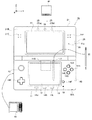
以下、本発明の一実施形態に係るゲーム装置について説明する。図1および図2A〜図2Dは、ゲーム装置10の外観を示す平面図である。ゲーム装置10は携帯型のゲーム装置であり、図1および図2A〜図2Dに示すように折り畳み可能に構成されている。図1は、開いた状態(開状態)におけるゲーム装置10を示し、図2A〜図2Dは、閉じた状態(閉状態)におけるゲーム装置10を示している。図1は、開状態におけるゲーム装置10の正面図である。ゲーム装置10は、撮像部によって画像を撮像し、撮像した画像を画面に表示したり、撮像した画像のデータを保存したりすることが可能である。また、ゲーム装置10は、交換可能なメモリカード内に記憶され、または、サーバーや他のゲーム装置から受信したゲームプログラムを実行可能であり、仮想空間に設定された仮想カメラで撮像した画像などのコンピュータグラフィックス処理により生成された画像を画面に表示したりすることができる。
(Configuration of game device)
Hereinafter, a game device according to an embodiment of the present invention will be described. 1 and 2A to 2D are plan views showing an appearance of the
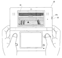
まず、図1および図2A〜図2Dを参照して、ゲーム装置10の外観構成について説明する。図1および図2A〜図2Dに示されるように、ゲーム装置10は、下側ハウジング11および上側ハウジング21を有する。下側ハウジング11と上側ハウジング21とは、開閉可能(折り畳み可能)に接続されている。
First, an external configuration of the
(下側ハウジングの説明)
まず、下側ハウジング11の構成について説明する。図1および図2A〜図2Dに示すように、下側ハウジング11には、下側LCD(Liquid Crystal Display:液晶表示装置)12、タッチパネル13、各操作ボタン14A〜14L、アナログスティック15、LED16A〜16B、挿入口17、および、マイクロフォン用孔18が設けられる。以下、これらの詳細について説明する。
(Description of lower housing)
First, the configuration of the
図1に示すように、下側LCD12は下側ハウジング11に収納される。下側LCD12の画素数は、例えば、320dot×240dot(横×縦)であってもよい。下側LCD12は、後述する上側LCD22とは異なり、画像を(立体視可能ではなく)平面的に表示する表示装置である。なお、本実施形態では表示装置としてLCDを用いているが、例えばEL(Electro Luminescence:電界発光)を利用した表示装置など、他の任意の表示装置を利用してもよい。また、下側LCD12として、任意の解像度の表示装置を利用することができる。
As shown in FIG. 1, the
図1に示されるように、ゲーム装置10は、入力装置として、タッチパネル13を備えている。タッチパネル13は、下側LCD12の画面上に装着されている。なお、本実施形態では、タッチパネル13は抵抗膜方式のタッチパネルである。ただし、タッチパネルは抵抗膜方式に限らず、例えば静電容量方式等、任意の方式のタッチパネルを用いることができる。本実施形態では、タッチパネル13として、下側LCD12の解像度と同解像度(検出精度)のものを利用する。ただし、必ずしもタッチパネル13の解像度と下側LCD12の解像度が一致している必要はない。また、下側ハウジング11の上側面には挿入口17(図1および図2Dに示す点線)が設けられている。挿入口17は、タッチパネル13に対する操作を行うために用いられるタッチペン28を収納することができる。なお、タッチパネル13に対する入力は通常タッチペン28を用いて行われるが、タッチペン28に限らずユーザの指でタッチパネル13に対する入力をすることも可能である。
As shown in FIG. 1, the
各操作ボタン14A〜14Lは、所定の入力を行うための入力装置である。図1に示されるように、下側ハウジング11の内側面(主面)には、各操作ボタン14A〜14Lのうち、十字ボタン14A(方向入力ボタン14A)、ボタン14B、ボタン14C、ボタン14D、ボタン14E、電源ボタン14F、セレクトボタン14J、HOMEボタン14K、およびスタートボタン14Lが、設けられる。十字ボタン14Aは、十字の形状を有しており、上下左右の方向を指示するボタンを有している。ボタン14A〜14E、セレクトボタン14J、HOMEボタン14K、およびスタートボタン14Lには、ゲーム装置10が実行するプログラムに応じた機能が適宜割り当てられる。例えば、十字ボタン14Aは選択操作等に用いられ、各操作ボタン14B〜14Eは例えば決定操作やキャンセル操作等に用いられる。また、電源ボタン14Fは、ゲーム装置10の電源をオン/オフするために用いられる。
Each
アナログスティック15は、方向を指示するデバイスである。アナログスティック15は、そのキートップが、下側ハウジング11の内側面に平行にスライドするように構成されている。アナログスティック15は、ゲーム装置10が実行するプログラムに応じて機能する。例えば、3次元仮想空間に所定のオブジェクトが登場するゲームがゲーム装置10によって実行される場合、アナログスティック15は、当該所定のオブジェクトを3次元仮想空間内で移動させるための入力装置として機能する。この場合において、所定のオブジェクトはアナログスティック15のキートップがスライドした方向に移動される。なお、アナログスティック15として、上下左右および斜め方向の任意の方向に所定量だけ傾倒することでアナログ入力を可能としたものを用いても良い。
The
また、下側ハウジング11の内側面には、マイクロフォン用孔18が設けられる。マイクロフォン用孔18の下部には後述する音声入力装置としてのマイク42(図4参照)が設けられ、当該マイク42がゲーム装置10の外部の音を検出する。
A
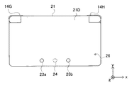
図2Aは閉状態におけるゲーム装置10の左側面図であり、図2Bは閉状態におけるゲーム装置10の正面図であり、図2Cは閉状態におけるゲーム装置10の右側面図であり、図2Dは閉状態におけるゲーム装置10の背面図である。図2Bおよび図2Dに示されるように、下側ハウジング11の上側面には、Lボタン14GおよびRボタン14Hが設けられている。Lボタン14GおよびRボタン14Hは、例えば、撮像部のシャッターボタン(撮影指示ボタン)として機能することができる。また、図2Aに示されるように、下側ハウジング11の左側面には、音量ボタン14Iが設けられる。音量ボタン14Iは、ゲーム装置10が備えるスピーカの音量を調整するために用いられる。
2A is a left side view of the
図2Aに示されるように、下側ハウジング11の左側面には開閉可能なカバー部11Cが設けられる。このカバー部11Cの内側には、ゲーム装置10とデータ保存用外部メモリ45とを電気的に接続するためのコネクタ(図示せず)が設けられる。データ保存用外部メモリ45は、コネクタに着脱自在に装着される。データ保存用外部メモリ45は、例えば、ゲーム装置10によって撮像された画像のデータを記憶(保存)するために用いられる。
As shown in FIG. 2A, an openable /
また、図2Dに示されるように、下側ハウジング11の上側面には、ゲーム装置10とゲームプログラムを記録した外部メモリ44を挿入するための挿入口11Dが設けられ、その挿入口11Dの内部には、外部メモリ44と電気的に着脱自在に接続するためのコネクタ(図示せず)が設けられる。当該外部メモリ44がゲーム装置10に接続されることにより、所定のゲームプログラムが実行される。
As shown in FIG. 2D, an
また、図1および図2Cに示されるように、下側ハウジング11の下側面にはゲーム装置10の電源のON/OFF状況をユーザに通知する第1LED16A、下側ハウジング11の右側面にはゲーム装置10の無線通信の確立状況をユーザに通知する第2LED16Bが設けられる。ゲーム装置10は他の機器との間で無線通信を行うことが可能であり、第2LED16Bは、無線通信が確立している場合に点灯する。ゲーム装置10は、例えば、IEEE802.11b/gの規格に準拠した方式により、無線LANに接続する機能を有する。下側ハウジング11の右側面には、この無線通信の機能を有効/無効にする無線スイッチ19が設けられる(図2C参照)。
Further, as shown in FIGS. 1 and 2C, the lower side of the
なお、図示は省略するが、下側ハウジング11には、ゲーム装置10の電源となる充電式電池が収納され、下側ハウジング11の側面(例えば、上側面)に設けられた端子を介して当該電池を充電することができる。
Although not shown, the
(上側ハウジングの説明)
次に、上側ハウジング21の構成について説明する。図1および図2A〜図2Dに示すように、上側ハウジング21には、上側LCD(Liquid Crystal Display:液晶表示装置)22、外側撮像部23(外側撮像部(左)23aおよび外側撮像部(右)23b)、内側撮像部24、3D調整スイッチ25、および、3Dインジケータ26が設けられる。以下、これらの詳細について説明する。
(Description of upper housing)
Next, the configuration of the
図1に示すように、上側LCD22は上側ハウジング21に収納される。上側LCD22の画素数は、例えば、800dot×240dot(横×縦)であってもよい。なお、本実施形態では上側LCD22は液晶表示装置であるとしたが、例えばEL(Electro Luminescence:電界発光)を利用した表示装置などが利用されてもよい。また、上側LCD22として、任意の解像度の表示装置を利用することができる。
As shown in FIG. 1, the
上側LCD22は、立体視可能な画像を表示することが可能な表示装置である。また、本実施例では、実質的に同一の表示領域を用いて左目用画像と右目用画像が表示される。具体的には、左目用画像と右目用画像が所定単位で(例えば、1列ずつ)横方向に交互に表示される方式の表示装置である。または、左目用画像と右目用画像とが交互に表示される方式の表示装置であってもよい。また、本実施例では、裸眼立体視可能な表示装置である。そして、横方向に交互に表示される左目用画像と右目用画像とを左目および右目のそれぞれに分解して見えるようにレンチキュラー方式やパララックスバリア方式(視差バリア方式)のものが用いられる。本実施形態では、上側LCD22はパララックスバリア方式のものとする。上側LCD22は、右目用画像と左目用画像とを用いて、裸眼で立体視可能な画像(立体画像)を表示する。すなわち、上側LCD22は、視差バリアを用いてユーザの左目に左目用画像をユーザの右目に右目用画像を視認させることにより、ユーザにとって立体感のある立体画像(立体視可能な画像)を表示することができる。また、上側LCD22は、上記視差バリアを無効にすることが可能であり、視差バリアを無効にした場合は、画像を平面的に表示することができる(上述した立体視とは反対の意味で平面視の画像を表示することができる。すなわち、表示された同一の画像が右目にも左目にも見えるような表示モードである)。このように、上側LCD22は、立体視可能な画像を表示する立体表示モードと、画像を平面的に表示する(平面視画像を表示する)平面表示モードとを切り替えることが可能な表示装置である。この表示モードの切り替えは、後述する3D調整スイッチ25によって行われる。
The
外側撮像部23は、上側ハウジング21の外側面(上側LCD22が設けられた主面と反対側の背面)21Dに設けられた2つの撮像部(23aおよび23b)の総称である。外側撮像部(左)23aと外側撮像部(右)23bの撮像方向は、いずれも当該外側面21Dの外向きの法線方向である。外側撮像部(左)23aと外側撮像部(右)23bとは、ゲーム装置10が実行するプログラムによって、ステレオカメラとして使用することが可能である。外側撮像部(左)23aおよび外側撮像部(右)23bは、それぞれ所定の共通の解像度を有する撮像素子(例えば、CCDイメージセンサやCMOSイメージセンサ等)と、レンズとを含む。レンズは、ズーム機構を有するものでもよい。
The
内側撮像部24は、上側ハウジング21の内側面(主面)21Bに設けられ、当該内側面の内向きの法線方向を撮像方向とする撮像部である。内側撮像部24は、所定の解像度を有する撮像素子(例えば、CCDイメージセンサやCMOSイメージセンサ等)と、レンズとを含む。レンズは、ズーム機構を有するものでもよい。
The
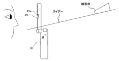
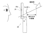
3D調整スイッチ25は、スライドスイッチであり、上述のように上側LCD22の表示モードを切り替えるために用いられるスイッチである。また、3D調整スイッチ25は、上側LCD22に表示された立体視可能な画像(立体画像)の立体感(立体視の強さ)を調整するために用いられる。3D調整スイッチ25のスライダ25aは、所定方向(上下方向)の任意の位置にスライド可能であり、当該スライダ25aの位置に応じて上側LCD22の表示モードが設定される。また、スライダ25aの位置に応じて、立体画像の見え方(立体視の強さ)が調整される。
The
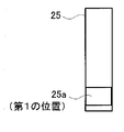
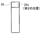
図3Aから図3Cは、3D調整スイッチ25のスライダ25aがスライドする様子を示す図である。図3Aは、3D調整スイッチ25のスライダ25aが最下点(第3の位置)に存在する様子を示す図である。図3Bは、3D調整スイッチ25のスライダ25aが最下点よりも上方位置(第1の位置)に存在する様子を示す図である。図3Cは、3D調整スイッチ25のスライダ25aが最上点(第2の位置)に存在する様子を示す図である。
3A to 3C are views showing how the
図3Aに示すように、3D調整スイッチ25のスライダ25aが最下点位置(第3の位置)に存在する場合、上側LCD22は平面表示モードに設定され、上側LCD22の画面には平面視画像が表示される(なお、上側LCD22を立体表示モードのままとして、左目用画像と右目用画像を同一の画像とすることにより平面表示してもよい)。一方、図3Bに示す位置(最下点より上側の位置(第1の位置))から図3Cに示す位置(最上点の位置(第2の位置))までの間にスライダ25aが存在する場合、上側LCD22は立体表示モードに設定される。この場合、上側LCD22の画面には立体視可能な画像が表示される。スライダ25aが第1の位置から第2の位置の間に存在する場合、スライダ25aの位置に応じて、立体画像の見え方が調整される。
As shown in FIG. 3A, when the
3Dインジケータ26は、上側LCD22が立体表示モードか否かを示す。3Dインジケータ26は、LEDであり、上側LCD22の立体表示モードが有効の場合に点灯する。なお、3Dインジケータ26は、上側LCD22が立体表示モードになっており、かつ、立体視画像を表示するプログラム処理が実行されているときに限り、点灯するようにしてもよい。
The
また、上側ハウジング21の内側面には、スピーカ孔21Eが設けられる。後述するスピーカ43からの音声がこのスピーカ孔21Eから出力される。
A
(ゲーム装置10の内部構成)
次に、図4を参照して、ゲーム装置10の内部の電気的構成について説明する。図4は、ゲーム装置10の内部構成を示すブロック図である。図4に示すように、ゲーム装置10は、上述した各部に加えて、情報処理部31、メインメモリ32、外部メモリインターフェイス(外部メモリI/F)33、データ保存用外部メモリI/F34、データ保存用内部メモリ35、無線通信モジュール36、ローカル通信モジュール37、リアルタイムクロック(RTC)38、加速度センサ39、電源回路40、およびインターフェイス回路(I/F回路)41等の電子部品を備えている。これらの電子部品は、電子回路基板上に実装されて下側ハウジング11(または上側ハウジング21でもよい)内に収納される。
(Internal configuration of game device 10)
Next, with reference to FIG. 4, an internal electrical configuration of the
情報処理部31は、所定のプログラムを実行するためのCPU(Central Processing Unit)311、画像処理を行うGPU(Graphics Processing Unit)312等を含む情報処理手段である。情報処理部31のCPU311は、ゲーム装置10内のメモリ(例えば外部メモリI/F33に接続された外部メモリ44やデータ保存用内部メモリ35)に記憶されているプログラムを実行することによって、当該プログラムに応じた処理を実行する。なお、情報処理部31のCPU311によって実行されるプログラムは、他の機器との通信によって他の機器から取得されてもよい。また、情報処理部31は、VRAM(Video RAM)313を含む。情報処理部31のGPU312は、情報処理部31のCPU311からの命令に応じて画像を生成し、VRAM313に描画する。そして、情報処理部31のGPU312は、VRAM313に描画された画像を上側LCD22及び/又は下側LCD12に出力し、上側LCD22及び/又は下側LCD12に当該画像が表示される。
The
情報処理部31には、メインメモリ32、外部メモリI/F33、データ保存用外部メモリI/F34、および、データ保存用内部メモリ35が接続される。外部メモリI/F33は、外部メモリ44を着脱自在に接続するためのインターフェイスである。また、データ保存用外部メモリI/F34は、データ保存用外部メモリ45を着脱自在に接続するためのインターフェイスである。
A
メインメモリ32は、情報処理部31(のCPU311)のワーク領域やバッファ領域として用いられる揮発性の記憶手段である。すなわち、メインメモリ32は、上記プログラムに基づく処理に用いられる各種データを一時的に記憶したり、外部(外部メモリ44や他の機器等)から取得されるプログラムを一時的に記憶したりする。本実施形態では、メインメモリ32として例えばPSRAM(Pseudo−SRAM)を用いる。
The
外部メモリ44は、情報処理部31によって実行されるプログラムを記憶するための不揮発性の記憶手段である。外部メモリ44は、例えば読み取り専用の半導体メモリで構成される。外部メモリ44が外部メモリI/F33に接続されると、情報処理部31は外部メモリ44に記憶されたプログラムを読み込むことができる。情報処理部31が読み込んだプログラムを実行することにより、所定の処理が行われる。データ保存用外部メモリ45は、不揮発性の読み書き可能なメモリ(例えばNAND型フラッシュメモリ)で構成され、所定のデータを格納するために用いられる。例えば、データ保存用外部メモリ45には、外側撮像部23で撮像された画像や他の機器で撮像された画像が記憶される。データ保存用外部メモリ45がデータ保存用外部メモリI/F34に接続されると、情報処理部31はデータ保存用外部メモリ45に記憶された画像を読み込み、上側LCD22及び/又は下側LCD12に当該画像を表示することができる。
The
データ保存用内部メモリ35は、読み書き可能な不揮発性メモリ(例えばNAND型フラッシュメモリ)で構成され、所定のデータを格納するために用いられる。例えば、データ保存用内部メモリ35には、無線通信モジュール36を介した無線通信によってダウンロードされたデータやプログラムが格納される。
The data storage
無線通信モジュール36は、例えばIEEE802.11b/gの規格に準拠した方式により、無線LANに接続する機能を有する。また、ローカル通信モジュール37は、所定の通信方式(例えば独自プロトコルによる通信や、赤外線通信)により同種のゲーム装置との間で無線通信を行う機能を有する。無線通信モジュール36およびローカル通信モジュール37は情報処理部31に接続される。情報処理部31は、無線通信モジュール36を用いてインターネットを介して他の機器との間でデータを送受信したり、ローカル通信モジュール37を用いて同種の他のゲーム装置との間でデータを送受信したりすることができる。
The
また、情報処理部31には、加速度センサ39が接続される。加速度センサ39は、3軸(xyz軸)方向に沿った直線方向の加速度(直線加速度)の大きさを検出する。加速度センサ39は、下側ハウジング11の内部に設けられる。加速度センサ39は、図1に示すように、下側ハウジング11の長辺方向をx軸、下側ハウジング11の短辺方向をy軸、下側ハウジング11の内側面(主面)に対して垂直な方向をz軸として、各軸の直線加速度の大きさを検出する。なお、加速度センサ39は、例えば静電容量式の加速度センサであるとするが、他の方式の加速度センサを用いるようにしてもよい。また、加速度センサ39は1軸又は2軸方向を検出する加速度センサであってもよい。情報処理部31は、加速度センサ39が検出した加速度を示すデータ(加速度データ)を受信して、ゲーム装置10の姿勢や動きを検出することができる。
An
また、情報処理部31には、RTC38および電源回路40が接続される。RTC38は、時間をカウントして情報処理部31に出力する。情報処理部31は、RTC38によって計時された時間に基づき現在時刻(日付)を計算する。電源回路40は、ゲーム装置10が有する電源(下側ハウジング11に収納される上記充電式電池)からの電力を制御し、ゲーム装置10の各部品に電力を供給する。
Further, the
また、情報処理部31には、I/F回路41が接続される。I/F回路41には、マイク42およびスピーカ43が接続される。具体的には、I/F回路41には、図示しないアンプを介してスピーカ43が接続される。マイク42は、ユーザの音声を検知して音声信号をI/F回路41に出力する。アンプは、I/F回路41からの音声信号を増幅し、音声をスピーカ43から出力させる。また、タッチパネル13はI/F回路41に接続される。I/F回路41は、マイク42およびスピーカ43(アンプ)の制御を行う音声制御回路と、タッチパネルの制御を行うタッチパネル制御回路とを含む。音声制御回路は、音声信号に対するA/D変換およびD/A変換を行ったり、音声信号を所定の形式の音声データに変換したりする。タッチパネル制御回路は、タッチパネル13からの信号に基づいて所定の形式のタッチ位置データを生成して情報処理部31に出力する。タッチ位置データは、タッチパネル13の入力面において入力が行われた位置の座標を示す。なお、タッチパネル制御回路は、タッチパネル13からの信号の読み込み、および、タッチ位置データの生成を所定時間に1回の割合で行う。情報処理部31は、タッチ位置データを取得することにより、タッチパネル13に対して入力が行われた位置を知ることができる。
In addition, an I /
操作ボタン14は、上記各操作ボタン14A〜14Lからなり、情報処理部31に接続される。操作ボタン14から情報処理部31へは、各操作ボタン14A〜14Iに対する入力状況(押下されたか否か)を示す操作データが出力される。情報処理部31は、操作ボタン14から操作データを取得することによって、操作ボタン14に対する入力に従った処理を実行する。
The
下側LCD12および上側LCD22は情報処理部31に接続される。下側LCD12および上側LCD22は、情報処理部31(のGPU312)の指示に従って画像を表示する。本実施形態では、情報処理部31は、上側LCD22に立体画像(立体視可能な画像)を表示させる。
The
具体的には、情報処理部31は、上側LCD22のLCDコントローラ(図示せず)と接続され、当該LCDコントローラに対して視差バリアのON/OFFを制御する。上側LCD22の視差バリアがONになっている場合、情報処理部31のVRAM313に格納された右目用画像と左目用画像とが、上側LCD22に出力される。より具体的には、LCDコントローラは、右目用画像について縦方向に1ライン分の画素データを読み出す処理と、左目用画像について縦方向に1ライン分の画素データを読み出す処理とを交互に繰り返すことによって、VRAM313から右目用画像と左目用画像とを読み出す。これにより、右目用画像および左目用画像が、画素を縦に1ライン毎に並んだ短冊状画像に分割され、分割された右目用画像の短冊状画像と左目用画像の短冊状画像とが交互に配置された画像が、上側LCD22の画面に表示される。そして、上側LCD22の視差バリアを介して当該画像がユーザに視認されることによって、ユーザの右目に右目用画像が、ユーザの左目に左目用画像が視認される。以上により、上側LCD22の画面には立体視可能な画像が表示される。
Specifically, the
外側撮像部23および内側撮像部24は、情報処理部31に接続される。外側撮像部23および内側撮像部24は、情報処理部31の指示に従って画像を撮像し、撮像した画像データを情報処理部31に出力する。
The
3D調整スイッチ25は、情報処理部31に接続される。3D調整スイッチ25は、スライダ25aの位置に応じた電気信号を情報処理部31に送信する。
The
また、3Dインジケータ26は、情報処理部31に接続される。情報処理部31は、3Dインジケータ26の点灯を制御する。例えば、情報処理部31は、上側LCD22が立体表示モードである場合、3Dインジケータ26を点灯させる。以上がゲーム装置10の内部構成の説明である。
The
(ゲーム装置10の動作の概要)
次に、図5〜図12を参照して、ゲーム装置10の動作の概要を説明する。ここでは、一例として、ゲーム装置10において、ユーザの操作に応じてライダーがコース上を走るゲームが実行される場合について説明する。
(Outline of operation of game device 10)
Next, an outline of the operation of the
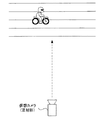
図5は、3D調整スイッチ25によって平面表示モードが選択されているとき(すなわち、3D調整スイッチ25のスライダ25aをユーザが第3の位置(図3A)に合わせたとき)に、ゲーム装置10の上側LCD22に表示されるゲーム画像の一例を示している。上側LCD22には、コース上を走るライダーや、コース上の障害物や、観客席などが表示されている。
FIG. 5 shows the
平面表示モードにおいては、図6に示すように、正射影の仮想カメラを用いて仮想空間を描画する(すなわち、仮想空間を所定の平面に向けて正射影する)ことによって、平面視画像が生成される。そして、こうして生成された平面視画像が上側LCD22に表示される。このように正射影により生成された画像は、昔のビデオゲームでよく見られた懐かしい画像であって、奥行き感の乏しい、リアル性に欠ける画像である。
In the planar display mode, as shown in FIG. 6, a planar image is generated by drawing a virtual space using an orthographic virtual camera (ie, projecting the virtual space toward a predetermined plane). Is done. Then, the planar view image generated in this way is displayed on the
なお、平面表示モードにおいては、透視投影の仮想カメラを用いてもよい。この場合には、透視投影の仮想カメラの画角を0または0に近い値に設定することにより、正射影の仮想カメラまたは疑似正射影の仮想カメラとして用いることができる。 In the planar display mode, a perspective projection virtual camera may be used. In this case, by setting the angle of view of the perspective projection virtual camera to 0 or a value close to 0, it can be used as an orthographic virtual camera or a pseudo orthographic virtual camera.
なお、既存のビデオゲーム(例えば昔のビデオゲーム)を、平面表示と立体表示の両方に対応したものへと改良(グレードアップ)する場合には、平面表示時は、リアル性を高めるよりも、むしろ既存のビデオゲームにおける画像の見た目を維持して、ユーザに懐かしさを感じさせたいという要望がある。 In addition, when improving an existing video game (for example, an old video game) to one that supports both flat display and stereoscopic display (upgrading), at the time of flat display, Rather, there is a desire to maintain the appearance of images in existing video games and make the user feel nostalgic.
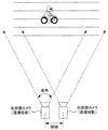
図7は、3D調整スイッチ25によって立体表示モードが選択され、かつ立体視の強さが最大値に設定されているとき(すなわち、3D調整スイッチ25のスライダ25aをユーザが第2の位置(図3C)に合わせたとき)に、ゲーム装置10の上側LCD22に表示されるゲーム画像の一例を示している。
7 shows that when the stereoscopic display mode is selected by the
立体表示モードにおいては、図8に示すように、間隔を空けて配置された透視投影の2つの仮想カメラ(右仮想カメラおよび左仮想カメラ)を用いて仮想空間を撮像することによって、2つの画像(右目用画像および左目用画像)が描画・生成される。そして、こうして生成された右目用画像および左目用画像を合成した立体視画像が上側LCD22に表示される。
In the stereoscopic display mode, as shown in FIG. 8, two images are obtained by capturing a virtual space using two perspective projection virtual cameras (right virtual camera and left virtual camera) arranged at intervals. (Right-eye image and left-eye image) are drawn and generated. A stereoscopic image obtained by synthesizing the right-eye image and the left-eye image generated in this way is displayed on the
このように、立体表示モードにおいては、間隔を空けて配置された2つの仮想カメラを用いて仮想空間を描画するので、右目用画像と左目用画像には視差が生じる。その結果として、図9に示すように、ユーザは視差によって感じられる奥行き感を感じることができる。また、立体表示モードにおいては、透視投影によって画像が描画されるので、正射影によって描画された画像と比べて、奥行き感とリアル性がより増す。 As described above, in the stereoscopic display mode, since the virtual space is drawn using two virtual cameras arranged at intervals, parallax occurs between the right-eye image and the left-eye image. As a result, as shown in FIG. 9, the user can feel a sense of depth felt by parallax. In the stereoscopic display mode, an image is drawn by perspective projection, so that a sense of depth and realism are further increased as compared to an image drawn by orthographic projection.
図10は、3D調整スイッチ25によって立体表示モードが選択され、かつ立体視の強さが最小値と最大値のほぼ中間に設定されているとき(すなわち、3D調整スイッチ25のスライダ25aをユーザが第1の位置(図3B)と第2の位置(図3C)のほぼ中間に合わせたとき)に、ゲーム装置10の上側LCD22に表示されるゲーム画像の一例を示している。
FIG. 10 shows that when the stereoscopic display mode is selected by the
この場合は、立体視の強さが最大値であるときと比べて、右仮想カメラと左仮想カメラの間隔は狭まり、かつ、各仮想カメラの画角は小さくなる。右仮想カメラと左仮想カメラの間隔が狭まることによって、右目用画像と左目用画像の視差が減るため、図11に示すように、立体視の強さが最大値であるときと比べて、視差によって感じられる奥行き感は減る。また、各仮想カメラの画角が小さくなることによって、透視投影によって感じられる奥行き感も減る。 In this case, the distance between the right virtual camera and the left virtual camera is narrower and the angle of view of each virtual camera is smaller than when the intensity of stereoscopic vision is the maximum value. As the distance between the right virtual camera and the left virtual camera is narrowed, the parallax between the right-eye image and the left-eye image is reduced. Therefore, as illustrated in FIG. The feeling of depth felt by is reduced. In addition, since the angle of view of each virtual camera is reduced, the sense of depth felt by perspective projection is also reduced.
なお、本実施形態では、立体視の強さは、3D調整スイッチ25からの出力信号に基づく3Dボリューム値に応じて決定される。3Dボリューム値は、例えば0.0〜1.0の範囲の実数値であって、スライダ25aが第1の位置(図3B)にあるときには0.0となり、スライダ25aが第1の位置から第3の位置に近づくほど大きくなり、スライダ25aが第2の位置(図3C)にあるときには1.0となる。
In the present embodiment, the strength of stereoscopic vision is determined according to the 3D volume value based on the output signal from the
なお、他の実施形態では、3Dボリューム値は、スライダ25aが第3の位置(図3A)にあるときには0.0となり、スライダ25aが第1の位置(図3B)にあるときには0.0に近い正の値となり、スライダ25aが第1の位置から第2の位置(図3C)に近づくほど大きくなり、スライダ25aが第2の位置にあるときには1.0となってもよい。この場合、3Dボリューム値が最小値のとき(すなわち、スライダ25aが第3の位置にあるとき)には、右仮想カメラと左仮想カメラを疑似正射影仮想カメラ(すなわち、仮想カメラの間隔を0または0に近い値にし、仮想カメラの画角を0に近い値とする)として利用して、右仮想カメラと左仮想カメラの一方の疑似正射影仮想カメラだけを用いて、上側LCD22に、平面視画像を表示するようにしてもよい。なお、平面視画像を表示する代わりに、右仮想カメラと左仮想カメラの両方の疑似正射影仮想カメラを用いて平面視画像に近い立体視画像を生成してもよい。
In other embodiments, the 3D volume value is 0.0 when the
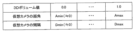
右仮想カメラと左仮想カメラのそれぞれの画角と、右仮想カメラと左仮想カメラの間隔は、上記の3Dボリューム値に応じて決定される。図12に示すように、右仮想カメラと左仮想カメラのそれぞれの画角は、3Dボリューム値が0.0のときは予め定められた最小画角Aminとなり、3Dボリューム値が大きくなるほど大きくなり、3Dボリューム値が1.0のときは予め定められた最大画角Amaxとなる。また、右仮想カメラと左仮想カメラの間隔は、3Dボリューム値が0.0のときは予め定められた最小間隔Dmin(0または0に近い値)となり、3Dボリューム値が大きくなるほど大きくなり、3Dボリューム値が1.0のときは予め定められた最大間隔Dmaxとなる。 The respective angles of view of the right virtual camera and the left virtual camera and the interval between the right virtual camera and the left virtual camera are determined according to the 3D volume value. As shown in FIG. 12, the angle of view of each of the right virtual camera and the left virtual camera becomes a predetermined minimum angle of view Amin when the 3D volume value is 0.0, and increases as the 3D volume value increases. When the 3D volume value is 1.0, the maximum angle of view Amax is set in advance. The interval between the right virtual camera and the left virtual camera is a predetermined minimum interval Dmin (0 or a value close to 0) when the 3D volume value is 0.0, and increases as the 3D volume value increases. When the volume value is 1.0, a predetermined maximum distance Dmax is obtained.
3Dボリューム値に応じた仮想カメラの設定のための計算式の一例を下記に示す。なお、下記の計算式において、m3DVol(0.0f〜1.0f)は3Dボリューム値を表しており、mFov2Lenは、3Dボリューム値が最小であるときの描画対象(仮想オブジェクト)から仮想カメラまでの距離を表しており、mMaxFovは、3Dボリューム値が最大であるときの仮想カメラの画角を表している。なお、単に仮想カメラの画角を大きくすると、画面に表示される描画対象の大きさが小さくなってしまうので、本実施形態では、下記の計算式のように、仮想カメラの画角(下記の画角設定値)が大きくなるほど仮想カメラ座標が小さくなる(すなわち、仮想カメラを描画対象に近づける)ようにすることで、画面に表示される描画対象の大きさが維持されるようにしている。
画角設定値=1.0f+(mMaxFov*m3DVol)
仮想カメラ座標=mFov2Len/画角設定値−((画角設定値*画角係数)/mFov2Len)
上記の計算結果に基づいて透視投影仮想カメラが設定される。
An example of a calculation formula for setting a virtual camera according to the 3D volume value is shown below. In the following calculation formula, m3DVol (0.0f to 1.0f) represents the 3D volume value, and mFov2Len represents the distance from the drawing target (virtual object) to the virtual camera when the 3D volume value is minimum. MMaxFov represents the angle of view of the virtual camera when the 3D volume value is maximum. Note that if the angle of view of the virtual camera is simply increased, the size of the drawing target displayed on the screen will be reduced. In this embodiment, the angle of view of the virtual camera (the following The size of the drawing target displayed on the screen is maintained by decreasing the virtual camera coordinates (that is, bringing the virtual camera closer to the drawing target) as the (viewing angle setting value) increases.
Angle of view setting = 1.0f + (mMaxFov * m3DVol)
Virtual camera coordinates = mFov2Len / view angle setting value-((view angle setting value * view angle coefficient) / mFov2Len)
A perspective projection virtual camera is set based on the above calculation result.
なお、ユーザがスライダ25aを操作して、表示モードを平面表示モードから立体表示モードに(または、立体表示モードから平面表示モードに)切り替えたときに、画像の見た目がスムーズに変化するように、上記最小画角および上記最小間隔は、0に近い値であるのが望ましい。画角が0に近い仮想カメラは、疑似正射影仮想カメラであると言える。このような効果は、図3A〜図3Cに示す3D調整スイッチ25のように、平面表示モードに対応する第3の位置と、立体表示モードにおいて立体視の強さが最小値となるような第1の位置とが隣接しており、かつ、スライダ25aが第3の位置から離れるほど立体表示モードにおける立体視の強さが大きくなるようなスイッチを採用することにより、より効果的となる。
Note that when the user operates the
なお、立体表示モードのときも平面表示モードのときも同じ透視投影仮想カメラを用い、平面表示モードのときには、透視投影カメラの画角を最小値に設定することにより、正射影仮想カメラまたは疑似正射影仮想カメラとして利用し、立体表示モードのときには、立体視の強さが大きくなるにしたがって、透視投影仮想カメラの画角が大きくなるようにしてもよい。 Note that the same perspective projection virtual camera is used in both the stereoscopic display mode and the planar display mode. In the planar display mode, the orthographic projection virtual camera or the pseudo-normal projection camera is set by setting the angle of view of the perspective projection camera to the minimum value. It may be used as a projection virtual camera, and in the stereoscopic display mode, the angle of view of the perspective projection virtual camera may be increased as the strength of stereoscopic vision increases.
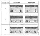
上記のような画角および間隔の制御により、左仮想カメラに基づいて描画される左目用画像と、右仮想カメラに基づいて描画される右目用画像は、3Dボリューム値に応じて図13に示すように変化する。 The left-eye image drawn based on the left virtual camera and the right-eye image drawn based on the right virtual camera by controlling the angle of view and the interval as described above are shown in FIG. 13 according to the 3D volume value. To change.
(ゲーム装置10の動作の詳細)
図14は、ゲーム装置10のメインメモリ32に格納されるプログラムおよびデータの一例を示している。メインメモリ32には、表示制御プログラム、仮想オブジェクトデータ、仮想カメラデータ、3Dボリューム値、操作データなどが格納される。
(Details of operation of game device 10)
FIG. 14 shows an example of programs and data stored in the
表示制御プログラムは、前述したような平面視画像および立体視画像を生成するためのプログラムであって、例えばゲーム開始時に、後述する仮想オブジェクトデータとともに、外部メモリ44等からメインメモリ32へとロードされる。
The display control program is a program for generating a planar image and a stereoscopic image as described above. For example, at the start of the game, the display control program is loaded from the
仮想オブジェクトデータは、仮想空間内の仮想オブジェクトに関するデータであって、仮想オブジェクトの形状や色などに関するデータである。また、仮想空間における仮想オブジェクトの位置や姿勢を示すデータも含まれており、これらのデータは、ゲームの進行に応じて随時更新される。 The virtual object data is data related to a virtual object in the virtual space, and is data related to the shape and color of the virtual object. Further, data indicating the position and orientation of the virtual object in the virtual space is also included, and these data are updated as needed as the game progresses.
仮想カメラデータは、仮想空間を描画するために用いられる仮想カメラに関するデータであって、仮想カメラの位置や姿勢等のデータが含まれる。仮想カメラデータには、平面視画像を生成する際に用いられる正射影仮想カメラに関するデータと、立体視画像を生成する際に用いられる透視投影仮想カメラ(右仮想カメラおよび左仮想カメラ)に関するデータが含まれている。透視投影仮想カメラに関するデータには、右仮想カメラおよび左仮想カメラのそれぞれの画角や、右仮想カメラと左仮想カメラの間隔(または右仮想カメラおよび左仮想カメラのそれぞれの座標位置)が含まれる。 The virtual camera data is data relating to a virtual camera used for drawing a virtual space, and includes data such as the position and orientation of the virtual camera. The virtual camera data includes data related to an orthographic virtual camera used when generating a planar view image and data related to a perspective projection virtual camera (right virtual camera and left virtual camera) used when generating a stereoscopic image. include. The data related to the perspective projection virtual camera includes the angle of view of each of the right virtual camera and the left virtual camera, and the interval between the right virtual camera and the left virtual camera (or the coordinate position of each of the right virtual camera and the left virtual camera). .
3Dボリューム値は、前述のように、3D調整スイッチ25からの出力信号に基づいて随時取得されて、メインメモリ32に格納される。
The 3D volume value is acquired as needed based on the output signal from the
操作データは、操作ボタン14等の入力装置からの出力信号に基づいて随時取得されて、メインメモリ32に格納される。
The operation data is acquired as needed based on an output signal from an input device such as the
図15は、表示制御プログラムに基づいて実行されるCPU311の処理の流れを示すフローチャートである。
FIG. 15 is a flowchart showing the flow of processing of the
まず、図15のステップS11で、CPU311は、仮想空間に仮想オブジェクト(地面、障害物、ライダー、観客席)を配置する。
First, in step S11 of FIG. 15, the
ステップS12では、CPU311は、3D調整スイッチ25からの出力信号に基づいて、立体表示モードが選択されているかどうか(すなわち、スライダ25aが第1の位置(図3B)から第2の位置(図3C)までの範囲に位置するかどうか)を判断する。そして、立体表示モードが選択されている場合には処理はステップS13に進み、そうでない場合(すなわち、平面表示モードが選択されている場合には処理はステップS16に進む。
In step S12, the
ステップS13では、CPU311は、3D調整スイッチ25からの出力信号に基づいて、3Dボリューム値を取得する。
In step S <b> 13, the
ステップS14では、CPU311は、取得した3Dボリューム値に基づいて、一対の透視投影仮想カメラ(すなわち、右仮想カメラおよび左仮想カメラ)のそれぞれの画角と、右仮想カメラと左仮想カメラの間隔(右仮想カメラおよび左仮想カメラのそれぞれの位置を示す座標)を決定する。これらは、図12に示すようなテーブルを参照して決定してもよいし、前述したような所定の計算式を用いて決定してもよい。
In step S14, the
ステップS15では、CPU311は、一対の透視投影仮想カメラを用いて画像(右目用画像および左目用画像)を描画する。この描画処理は、典型的には、CPU311からの描画指示に応じてGPU312によって行われる。こうして生成されたこれらの画像は、適宜に合成されて、所定のタイミングで上側LCD22に立体表示される。
In step S15, the
ステップS16では、CPU311は、1つの正射影仮想カメラを用いて画像を描画する。この描画処理は、典型的には、CPU311からの描画指示に応じてGPU312によって行われる。こうして生成された画像は、所定のタイミングで上側LCD22に平面表示される。
In step S16, the
ステップS17では、CPU311は、操作ボタン14等からの出力信号に基づいて、操作データを取得する。
In step S17, the
ステップS18では、CPU311は、取得した操作データに基づいて、仮想オブジェクト(本実施形態ではライダー)を制御する。
In step S18, the
ステップS19では、CPU311は、ゲームが終了したかどうかを判断し、ゲームが終了した場合には表示制御プログラムの実行を終了し、そうでない場合には処理はステップS12に戻る。
In step S19, the
(本実施形態の効果)
以上のように、本実施形態によれば、立体表示モードのときには透視投影仮想カメラが用いられ、平面表示モードのときには正射影仮想カメラが用いられる。よって、立体表示モードのときは、平面表示モードのときと比較して、視差によって感じられる奥行き感に加えて、透視投影によって感じられる奥行き感もユーザに感じさせることができ、立体感を強調することができる。
(Effect of this embodiment)
As described above, according to the present embodiment, the perspective projection virtual camera is used in the stereoscopic display mode, and the orthogonal projection virtual camera is used in the planar display mode. Therefore, in the stereoscopic display mode, in addition to the depth feeling felt by the parallax, the depth feeling felt by the perspective projection can be made to be felt by the user as compared with the planar display mode, and the stereoscopic effect is emphasized. be able to.
また、本実施形態によれば、立体表示モードのときに、立体視の強さ(すなわち、スライダ25aの位置)に応じて仮想カメラの画角が変化するので、立体視の強さが変化したときに、視差によって感じられる奥行き感の変化に加えて、透視投影によって感じられる奥行き感の変化もユーザに感じさせることができ、立体感の変化を強調することができる。
Further, according to the present embodiment, when the stereoscopic display mode is selected, the angle of view of the virtual camera changes according to the strength of stereoscopic vision (that is, the position of the
また、本実施形態によれば、立体表示モードのときも平面表示モードのときも透視投影仮想カメラが用いられ、平面表示モードのときには、透視投影カメラの画角を最小値に設定することにより、正射影仮想カメラまたは疑似正射影仮想カメラとして用いることができ、立体表示モードのときには、立体視の強さが大きくなるにしたがって、透視投影仮想カメラの画角が大きくなるように変化するので、立体視の強さが変化したときに、視差(左右の仮想カメラ間の距離)によって感じられる奥行き感の変化に加えて、透視投影カメラの画角によって感じられる奥行き感の変化もユーザに感じさせることができ、立体感の変化を強調することができる。 Further, according to the present embodiment, the perspective projection virtual camera is used in both the stereoscopic display mode and the planar display mode, and in the planar display mode, by setting the angle of view of the perspective projection camera to the minimum value, It can be used as an orthographic virtual camera or a pseudo orthographic virtual camera, and in the stereoscopic display mode, the angle of view of the perspective projection virtual camera changes as the stereoscopic strength increases. In addition to the change in depth perceived by parallax (distance between left and right virtual cameras) when the intensity of vision changes, the user also feels the change in depth perceived by the angle of view of the perspective projection camera It is possible to emphasize the change in stereoscopic effect.
(変形例)
なお、上記実施形態では、平面表示モードのときに正射影仮想カメラを用いて仮想空間を描画する例を説明したが、他の実施形態では、平面表示モードのときに、正射影に近い画角の透視投影仮想カメラ(疑似正射影仮想カメラ)を用いて仮想空間を描画するようにしてもよい。また、平面表示モードのときに、立体表示モードのときに用いられる一対の仮想カメラの間隔を0に設定(右仮想カメラおよび左仮想カメラのそれぞれの座標位置を同一に設定)し、それらのうちの一方の仮想カメラだけを用いて仮想空間を描画するようにしてもよい。
(Modification)
In the above embodiment, an example in which a virtual space is drawn using an orthographic virtual camera in the flat display mode has been described. However, in another embodiment, an angle of view close to the orthographic projection in the flat display mode. The virtual space may be drawn using the perspective projection virtual camera (pseudo orthographic virtual camera). Also, in the flat display mode, the interval between the pair of virtual cameras used in the stereoscopic display mode is set to 0 (the coordinate positions of the right virtual camera and the left virtual camera are set the same), The virtual space may be drawn using only one of the virtual cameras.
また、上記実施形態では、立体表示モードのときに一対の透視投影仮想カメラを用いる例を説明したが、他の実施形態では、立体表示モードのときに1つの透視投影仮想カメラを用いて、当該透視投影仮想カメラの位置を適宜にずらすことによって、視点の異なる2つの画像(右目用画像および左目用画像)を描画するようにしてもよい。 In the above embodiment, an example in which a pair of perspective projection virtual cameras are used in the stereoscopic display mode has been described. However, in another embodiment, a single perspective projection virtual camera is used in the stereoscopic display mode. Two images (right-eye image and left-eye image) with different viewpoints may be drawn by appropriately shifting the position of the perspective projection virtual camera.
また、上記実施形態では、平面表示モードのときと立体表示モードのときとで、正射影仮想カメラと透視投影仮想カメラとを切り替える例(2種類のカメラの切り替え)を説明したが、本発明はこれに限らず、平面表示モードのときと立体表示モードのときとで、仮想カメラのパラメータ(例えば画角など)を変化させさえすればよい。これにより、平面表示モードのときと立体表示モードのときとで、視差によって生じる奥行き感の変化に加えて、仮想カメラのパラメータに応じて画像の見た目も変化させることができる。あるいは、画角の大きさの異なる透視投影仮想カメラを複数種類用意しておき、取得した3Dボリューム値に基づいて、対応する透視投影仮想カメラを設定するようにしてもよい。 Moreover, although the said embodiment demonstrated the example (switching of two types of cameras) which switches an orthogonal projection virtual camera and a perspective projection virtual camera by the time of planar display mode and the time of a stereoscopic display mode, this invention is However, the present invention is not limited to this, and it is only necessary to change the parameters (for example, the angle of view) of the virtual camera between the flat display mode and the stereoscopic display mode. This makes it possible to change the appearance of the image in accordance with the parameters of the virtual camera, in addition to the change in the feeling of depth caused by the parallax between the flat display mode and the stereoscopic display mode. Alternatively, a plurality of types of perspective projection virtual cameras having different angles of view may be prepared, and corresponding perspective projection virtual cameras may be set based on the acquired 3D volume value.
また、上記実施形態では、ユーザがライダーを操作して遊ぶゲームが実行される例を説明したが、他の実施形態では、ゲーム以外の任意のアプリケーションソフトウェアが実行されてもよい。 Moreover, although the said embodiment demonstrated the example in which the game which a user plays by operating a rider was performed, arbitrary application software other than a game may be performed in other embodiment.
また、上記実施形態では、表示制御プログラムの処理がCPU(CPU311)によって実行される例を説明したが、他の実施形態では、表示制御プログラムの少なくとも一部の処理がハードウェアのみによって実現されてもよい。 In the above-described embodiment, an example in which the processing of the display control program is executed by the CPU (CPU 311) has been described. However, in other embodiments, at least a part of the processing of the display control program is realized only by hardware. Also good.
また、上記実施形態では、立体表示が可能な表示装置(上側LCD22)を備えた携帯型のゲーム装置について説明したが、他の実施形態では、立体表示が可能な表示装置へと画像信号を出力可能な任意の情報処理装置(据え置き型ゲーム装置、デスクトップパソコン、ノートパソコン、携帯電話など)を利用してもよい。 In the above embodiment, the portable game device including the display device (upper LCD 22) capable of stereoscopic display has been described. However, in other embodiments, an image signal is output to a display device capable of stereoscopic display. Any possible information processing device (a stationary game device, a desktop personal computer, a notebook personal computer, a mobile phone, etc.) may be used.
また、上記実施形態では、表示制御プログラムの処理が1つのCPU(CPU311)によって実行される例を説明したが、他の実施形態では、表示制御プログラムの処理が複数のプロセッサによって分担して実行されてもよい。また、これらの複数のプロセッサは、同一の情報処理装置に内蔵されていてもよいし、サーバー装置とクライアント装置のように複数の情報処理装置に分散して設けられていてもよい。 In the above-described embodiment, an example in which the processing of the display control program is executed by one CPU (CPU 311) has been described. However, in other embodiments, the processing of the display control program is executed by being shared by a plurality of processors. May be. Further, the plurality of processors may be built in the same information processing apparatus, or may be distributed and provided in a plurality of information processing apparatuses such as a server apparatus and a client apparatus.
10 ゲーム装置
11 下側ハウジング
21 上側ハウジング
22 上側LCD
25 3D調整スイッチ
25a スライダ
10
25
Claims (26)
立体視の強さを調整する調整手段、
前記調整手段によって調整された強さに応じて仮想カメラの画角を設定する仮想カメラ制御手段、および、
仮想空間に配置された仮想オブジェクトを前記仮想カメラ制御手段によって設定された前記仮想カメラに基づいて描画する描画手段として機能させる、表示制御プログラム。 Display control device computer,
Adjustment means for adjusting the strength of stereoscopic viewing;
Virtual camera control means for setting the angle of view of the virtual camera according to the strength adjusted by the adjusting means, and
A display control program that causes a virtual object placed in a virtual space to function as a drawing unit that draws based on the virtual camera set by the virtual camera control unit.
前記調整手段によって立体視の強さが第1の値に調整された場合には前記仮想カメラの画角を第1の画角に設定し、
前記調整手段によって立体視の強さが第2の値に調整された場合には前記仮想カメラの画角を第2の画角に設定し、
前記描画手段は、
前記カメラ制御手段によって前記仮想カメラの画角が第1の画角に設定されたときには、立体視画像を描画し、
前記カメラ制御手段によって前記仮想カメラの画角が第2の画角に設定されたときには、平面視画像を描画する、請求項1に記載の表示制御プログラム。 The virtual camera control means includes
When the stereoscopic intensity is adjusted to the first value by the adjusting means, the angle of view of the virtual camera is set to the first angle of view,
When the stereoscopic intensity is adjusted to the second value by the adjusting means, the angle of view of the virtual camera is set to the second angle of view,
The drawing means includes
When the angle of view of the virtual camera is set to the first angle of view by the camera control means, a stereoscopic image is drawn,
The display control program according to claim 1, wherein when the angle of view of the virtual camera is set to a second angle of view by the camera control unit, a planar view image is drawn.
前記描画手段は、前記一対の仮想カメラに基づいて前記仮想オブジェクトを撮像した左目用画像と右目用画像を描画することにより立体視画像を描画する、請求項1〜4のいずれか1項に記載の表示制御プログラム。 The virtual camera control means changes the interval between the pair of virtual cameras according to the strength adjusted by the adjusting means,
The said drawing means draws a stereoscopic vision image by drawing the image for left eyes and the image for right eyes which imaged the said virtual object based on said pair of virtual cameras. Display control program.
前記仮想カメラ制御手段は、前記調整手段によって立体視の強さが最小値に調整された場合には、前記一対の透視投影仮想カメラの画角を最小値に設定することにより正射影に近い画角に設定するとともに、前記一対の透視投影仮想カメラの間隔を0または0に近い値に設定する、請求項5または6に記載の表示制御プログラム。 The pair of virtual cameras are perspective projection virtual cameras;
The virtual camera control means sets an angle of view close to orthographic projection by setting the angle of view of the pair of perspective projection virtual cameras to the minimum value when the stereoscopic intensity is adjusted to the minimum value by the adjusting means. The display control program according to claim 5 or 6, wherein the display control program sets an angle and sets an interval between the pair of perspective projection virtual cameras to 0 or a value close to 0.
前記調整手段によって調整された強さに応じて仮想カメラの画角を設定する仮想カメラ制御手段、および、
仮想空間に配置された仮想オブジェクトを前記仮想カメラ制御手段によって設定された前記仮想カメラに基づいて描画する描画手段を備える、表示制御装置。 Adjustment means for adjusting the strength of stereoscopic viewing;
Virtual camera control means for setting the angle of view of the virtual camera according to the strength adjusted by the adjusting means, and
A display control apparatus comprising: a drawing unit that draws a virtual object arranged in a virtual space based on the virtual camera set by the virtual camera control unit.
前記調整ステップにおいて調整された強さに応じて仮想カメラの画角を設定する仮想カメラ制御ステップ、および、
仮想空間に配置された仮想オブジェクトを前記仮想カメラ制御ステップにおいて設定された前記仮想カメラに基づいて描画する描画ステップを備える、表示制御方法。 An adjustment step to adjust the strength of the stereoscopic view,
A virtual camera control step of setting a field angle of the virtual camera according to the strength adjusted in the adjustment step; and
A display control method, comprising: a drawing step of drawing a virtual object arranged in a virtual space based on the virtual camera set in the virtual camera control step.
前記調整手段によって調整された強さに応じて仮想カメラの画角を設定する仮想カメラ制御手段、および、
仮想空間に配置された仮想オブジェクトを前記仮想カメラ制御手段によって設定された前記仮想カメラに基づいて描画する描画手段を備える、表示制御システム。 Adjustment means for adjusting the strength of stereoscopic viewing;
Virtual camera control means for setting the angle of view of the virtual camera according to the strength adjusted by the adjusting means, and
A display control system comprising drawing means for drawing a virtual object placed in a virtual space based on the virtual camera set by the virtual camera control means.
立体視の強さを調整する調整手段、
前記調整手段によって調整された強さに応じて仮想カメラの種類を設定する仮想カメラ制御手段、および、
仮想空間に配置された仮想オブジェクトを前記仮想カメラ制御手段によって設定された仮想カメラに基づいて描画する描画手段として機能させる、表示制御プログラム。 Display control device computer,
Adjustment means for adjusting the strength of stereoscopic viewing;
Virtual camera control means for setting the type of virtual camera according to the strength adjusted by the adjusting means, and
A display control program for causing a virtual object placed in a virtual space to function as a drawing unit for drawing based on a virtual camera set by the virtual camera control unit.
前記調整手段によって立体視の強さが第1の値に調整された場合には、第1の仮想カメラを設定し、
前記調整手段によって立体視の強さが第2の値に調整された場合には、前記第1の仮想カメラとは種類の異なる第2の仮想カメラを設定し、
前記描画手段は、
前記第1の仮想カメラに基づいて前記仮想オブジェクトを撮像した立体視画像を描画し、
前記第2の仮想カメラに基づいて前記仮想オブジェクトを撮像した平面視画像を描画する、請求項13に記載の表示制御プログラム。 The virtual camera control means includes
If the stereoscopic intensity is adjusted to the first value by the adjusting means, the first virtual camera is set,
When the intensity of stereoscopic vision is adjusted to the second value by the adjusting means, a second virtual camera different from the first virtual camera is set,
The drawing means includes
Rendering a stereoscopic image obtained by imaging the virtual object based on the first virtual camera;
The display control program according to claim 13, wherein a planar view image obtained by capturing the virtual object is drawn based on the second virtual camera.
前記調整手段によって立体視の強さが第1の値に調整された場合には、透視投影仮想カメラを設定し、
前記調整手段によって立体視の強さが第2の値に調整された場合には、正射影仮想カメラ、または、疑似正射影仮想カメラを設定し、
前記描画手段は、
前記透視投影仮想カメラに基づいて前記仮想オブジェクトを撮像した立体視画像を描画し、
前記正射影仮想カメラ、または、疑似正射影仮想カメラに基づいて、前記仮想オブジェクトを撮像した平面視画像を描画する、請求項14に記載の表示制御プログラム。 The virtual camera control means includes
When the intensity of stereoscopic vision is adjusted to the first value by the adjusting means, a perspective projection virtual camera is set,
When the intensity of stereoscopic vision is adjusted to the second value by the adjusting means, an orthographic virtual camera or a pseudo orthographic virtual camera is set,
The drawing means includes
Drawing a stereoscopic image obtained by imaging the virtual object based on the perspective projection virtual camera,
The display control program according to claim 14, wherein a plan view image obtained by imaging the virtual object is drawn based on the orthographic virtual camera or the pseudo orthographic virtual camera.
前記描画手段は、前記仮想カメラ制御手段によって設定された画角の前記透視投影仮想カメラに基づいて、前記仮想オブジェクトを撮像した立体視画像を描画する、請求項15または16に記載の表示制御プログラム。 The virtual camera control means sets the angle of view of the perspective projection virtual camera according to the strength adjusted by the adjusting means,
The display control program according to claim 15 or 16, wherein the drawing means draws a stereoscopic image obtained by imaging the virtual object based on the perspective projection virtual camera having an angle of view set by the virtual camera control means. .
前記調整手段によって調整された強さが最小値であるときには、透視投影仮想カメラの画角を最小値に設定することにより、正射影に近い画角に設定し、
前記調整手段によって調整された強さが大きいほど、前記透視投影仮想カメラの画角を大きくする、請求項15〜17のいずれか1項に記載の表示制御プログラム。 The virtual camera control means includes
When the intensity adjusted by the adjusting means is the minimum value, by setting the angle of view of the perspective projection virtual camera to the minimum value, the angle of view close to orthographic projection is set,
The display control program according to any one of claims 15 to 17, wherein the angle of view of the perspective projection virtual camera is increased as the intensity adjusted by the adjustment unit is increased.
前記描画手段は、前記一対の透視投影仮想カメラに基づいて前記仮想オブジェクトを撮像した左目用画像と右目用画像を描画することにより立体視画像を描画する、請求項13〜18のいずれか1項に記載の表示制御プログラム。 The virtual camera control means sets an interval between a pair of perspective projection virtual cameras according to the strength adjusted by the adjusting means,
The rendering means renders a stereoscopic image by rendering a left-eye image and a right-eye image obtained by capturing the virtual object based on the pair of perspective projection virtual cameras. Display control program described in 1.
前記調整手段によって立体視の強さが前記第1の値に調整された場合には、一対の透視投影仮想カメラに基づいて前記仮想オブジェクトを撮像した左目用画像と右目用画像を描画することにより立体視画像を描画し、
前記調整手段によって立体視の強さが前記第2の値に調整された場合には、1つの正射影仮想カメラに基づいて前記仮想オブジェクトを撮像した平面視画像を描画する、請求項14に記載の表示制御プログラム。 The drawing means includes
When the intensity of stereoscopic vision is adjusted to the first value by the adjusting means, by drawing a left-eye image and a right-eye image obtained by capturing the virtual object based on a pair of perspective projection virtual cameras Draw a stereoscopic image,
The planar view image which imaged the virtual object based on one orthographic virtual camera is drawn when the intensity of stereoscopic vision is adjusted to the 2nd value by the adjustment means. Display control program.
前記調整手段によって調整された強さに応じて仮想カメラの種類を設定する仮想カメラ制御手段、および、
仮想空間に配置された仮想オブジェクトを前記仮想カメラ制御手段によって設定された仮想カメラに基づいて描画する描画手段を備える、表示制御装置。 Adjustment means for adjusting the strength of stereoscopic viewing;
Virtual camera control means for setting the type of virtual camera according to the strength adjusted by the adjusting means, and
A display control apparatus comprising: a drawing unit that draws a virtual object placed in a virtual space based on a virtual camera set by the virtual camera control unit.
前記調整ステップにおいて調整された強さに応じて仮想カメラの種類を設定する仮想カメラ制御ステップ、および、
仮想空間に配置された仮想オブジェクトを前記仮想カメラ制御手段において設定された仮想カメラに基づいて描画する描画ステップを備える、表示制御方法。 An adjustment step to adjust the strength of the stereoscopic view,
A virtual camera control step for setting the type of the virtual camera according to the strength adjusted in the adjustment step; and
A display control method comprising a drawing step of drawing a virtual object placed in a virtual space based on a virtual camera set by the virtual camera control means.
前記調整手段によって調整された強さに応じて仮想カメラの種類を設定する仮想カメラ制御手段、および、
仮想空間に配置された仮想オブジェクトを前記仮想カメラ制御手段によって設定された仮想カメラに基づいて描画する描画手段を備える、表示制御システム。 Adjustment means for adjusting the strength of stereoscopic viewing;
Virtual camera control means for setting the type of virtual camera according to the strength adjusted by the adjusting means, and
A display control system comprising drawing means for drawing a virtual object placed in a virtual space based on a virtual camera set by the virtual camera control means.
Priority Applications (3)
| Application Number | Priority Date | Filing Date | Title |
|---|---|---|---|
| JP2010294536A JP5876983B2 (en) | 2010-12-29 | 2010-12-29 | Display control program, display control device, display control method, and display control system |
| EP11160191.0A EP2471583B1 (en) | 2010-12-29 | 2011-03-29 | Display control program, display control method, and display control system |
| US13/081,911 US20120169717A1 (en) | 2010-12-29 | 2011-04-07 | Computer-readable storage medium, display control apparatus, display control method, and display control system |
Applications Claiming Priority (1)
| Application Number | Priority Date | Filing Date | Title |
|---|---|---|---|
| JP2010294536A JP5876983B2 (en) | 2010-12-29 | 2010-12-29 | Display control program, display control device, display control method, and display control system |
Publications (2)
| Publication Number | Publication Date |
|---|---|
| JP2012142804A true JP2012142804A (en) | 2012-07-26 |
| JP5876983B2 JP5876983B2 (en) | 2016-03-02 |
Family
ID=45771674
Family Applications (1)
| Application Number | Title | Priority Date | Filing Date |
|---|---|---|---|
| JP2010294536A Active JP5876983B2 (en) | 2010-12-29 | 2010-12-29 | Display control program, display control device, display control method, and display control system |
Country Status (3)
| Country | Link |
|---|---|
| US (1) | US20120169717A1 (en) |
| EP (1) | EP2471583B1 (en) |
| JP (1) | JP5876983B2 (en) |
Families Citing this family (7)
| Publication number | Priority date | Publication date | Assignee | Title |
|---|---|---|---|---|
| US10607398B2 (en) * | 2016-07-04 | 2020-03-31 | Colopl, Inc. | Display control method and system for executing the display control method |
| US10668382B2 (en) * | 2017-09-29 | 2020-06-02 | Sony Interactive Entertainment America Llc | Augmenting virtual reality video games with friend avatars |
| JP7301567B2 (en) * | 2019-03-20 | 2023-07-03 | 任天堂株式会社 | Image display system, image display program, image display device, and image display method |
| CN109976533B (en) * | 2019-04-15 | 2022-06-03 | 珠海天燕科技有限公司 | Display control method and device |
| US11430198B1 (en) * | 2020-01-10 | 2022-08-30 | Apple Inc. | Method and device for orientation-based view switching |
| CN113611181B (en) * | 2021-07-09 | 2023-06-13 | 中国舰船研究设计中心 | Stereoscopic display method and device for virtual simulation scene |
| CN115278202A (en) * | 2022-07-29 | 2022-11-01 | 联想(北京)有限公司 | Display method and device |
Citations (12)
| Publication number | Priority date | Publication date | Assignee | Title |
|---|---|---|---|---|
| JPH0974573A (en) * | 1995-06-29 | 1997-03-18 | Matsushita Electric Ind Co Ltd | Stereoscopic cg image generator |
| JPH0990277A (en) * | 1995-09-28 | 1997-04-04 | Terumo Corp | Stereoscopic picture display device |
| JP2001346226A (en) * | 2000-06-02 | 2001-12-14 | Canon Inc | Image processor, stereoscopic photograph print system, image processing method, stereoscopic photograph print method, and medium recorded with processing program |
| JP2003067784A (en) * | 2002-07-30 | 2003-03-07 | Canon Inc | Information processor |
| JP2003107603A (en) * | 2001-09-28 | 2003-04-09 | Namco Ltd | Stereophonic image generating device, stereophonic image generation information and information storage medium |
| JP2004220127A (en) * | 2003-01-09 | 2004-08-05 | Sanyo Electric Co Ltd | Stereoscopic image processing method and device |
| JP2005020559A (en) * | 2003-06-27 | 2005-01-20 | Univ Waseda | Three-dimensional video presentation apparatus |
| JP2005073013A (en) * | 2003-08-26 | 2005-03-17 | Sharp Corp | Device and method for stereo image display, program for making computer execute the method, and recording medium recording the program |
| JP2006107213A (en) * | 2004-10-06 | 2006-04-20 | Canon Inc | Stereoscopic image printing system |
| JP2008210405A (en) * | 2008-05-16 | 2008-09-11 | Sharp Corp | Image processing method, program to be computer executed for realizing the method, and recording medium with the program stored |
| JP2010154422A (en) * | 2008-12-26 | 2010-07-08 | Casio Computer Co Ltd | Image processor |
| JP2010237410A (en) * | 2009-03-31 | 2010-10-21 | Fujifilm Corp | Image display apparatus and method, and program |
Family Cites Families (7)
| Publication number | Priority date | Publication date | Assignee | Title |
|---|---|---|---|---|
| US5687410A (en) * | 1994-10-14 | 1997-11-11 | Nikon Corporation | Information setting apparatus of camera |
| US6005607A (en) * | 1995-06-29 | 1999-12-21 | Matsushita Electric Industrial Co., Ltd. | Stereoscopic computer graphics image generating apparatus and stereoscopic TV apparatus |
| WO2004049734A1 (en) * | 2002-11-28 | 2004-06-10 | Seijiro Tomita | Three-dimensional image signal producing circuit and three-dimensional image display apparatus |
| JP4489610B2 (en) * | 2005-01-28 | 2010-06-23 | 株式会社 日立ディスプレイズ | Stereoscopic display device and method |
| KR100667810B1 (en) * | 2005-08-31 | 2007-01-11 | 삼성전자주식회사 | Apparatus for controlling depth of 3d picture and method therefor |
| JP4513905B2 (en) * | 2008-06-27 | 2010-07-28 | ソニー株式会社 | Signal processing apparatus, signal processing method, program, and recording medium |
| US9350978B2 (en) * | 2009-05-29 | 2016-05-24 | Two Pic Mc Llc | Method of defining stereoscopic depth |
-
2010
- 2010-12-29 JP JP2010294536A patent/JP5876983B2/en active Active
-
2011
- 2011-03-29 EP EP11160191.0A patent/EP2471583B1/en active Active
- 2011-04-07 US US13/081,911 patent/US20120169717A1/en not_active Abandoned
Patent Citations (12)
| Publication number | Priority date | Publication date | Assignee | Title |
|---|---|---|---|---|
| JPH0974573A (en) * | 1995-06-29 | 1997-03-18 | Matsushita Electric Ind Co Ltd | Stereoscopic cg image generator |
| JPH0990277A (en) * | 1995-09-28 | 1997-04-04 | Terumo Corp | Stereoscopic picture display device |
| JP2001346226A (en) * | 2000-06-02 | 2001-12-14 | Canon Inc | Image processor, stereoscopic photograph print system, image processing method, stereoscopic photograph print method, and medium recorded with processing program |
| JP2003107603A (en) * | 2001-09-28 | 2003-04-09 | Namco Ltd | Stereophonic image generating device, stereophonic image generation information and information storage medium |
| JP2003067784A (en) * | 2002-07-30 | 2003-03-07 | Canon Inc | Information processor |
| JP2004220127A (en) * | 2003-01-09 | 2004-08-05 | Sanyo Electric Co Ltd | Stereoscopic image processing method and device |
| JP2005020559A (en) * | 2003-06-27 | 2005-01-20 | Univ Waseda | Three-dimensional video presentation apparatus |
| JP2005073013A (en) * | 2003-08-26 | 2005-03-17 | Sharp Corp | Device and method for stereo image display, program for making computer execute the method, and recording medium recording the program |
| JP2006107213A (en) * | 2004-10-06 | 2006-04-20 | Canon Inc | Stereoscopic image printing system |
| JP2008210405A (en) * | 2008-05-16 | 2008-09-11 | Sharp Corp | Image processing method, program to be computer executed for realizing the method, and recording medium with the program stored |
| JP2010154422A (en) * | 2008-12-26 | 2010-07-08 | Casio Computer Co Ltd | Image processor |
| JP2010237410A (en) * | 2009-03-31 | 2010-10-21 | Fujifilm Corp | Image display apparatus and method, and program |
Also Published As
| Publication number | Publication date |
|---|---|
| EP2471583B1 (en) | 2020-11-18 |
| EP2471583A2 (en) | 2012-07-04 |
| US20120169717A1 (en) | 2012-07-05 |
| JP5876983B2 (en) | 2016-03-02 |
| EP2471583A3 (en) | 2014-07-09 |
Similar Documents
| Publication | Publication Date | Title |
|---|---|---|
| JP5689707B2 (en) | Display control program, display control device, display control system, and display control method | |
| US9001192B2 (en) | Storage medium having stored therein stereoscopic image display program, stereoscopic image display device, stereoscopic image display system, and stereoscopic image display method | |
| US9693039B2 (en) | Hand-held electronic device | |
| JP5702653B2 (en) | Information processing program, information processing apparatus, information processing system, and information processing method | |
| JP5876983B2 (en) | Display control program, display control device, display control method, and display control system | |
| US20120242807A1 (en) | Hand-held electronic device | |
| JP2012003350A (en) | Image display program, device, system, and method | |
| JP2012139318A (en) | Display control program, display control apparatu, display control system, and display control method | |
| US20120293549A1 (en) | Computer-readable storage medium having information processing program stored therein, information processing apparatus, information processing system, and information processing method | |
| JP5689637B2 (en) | Stereoscopic display control program, stereoscopic display control system, stereoscopic display control apparatus, and stereoscopic display control method | |
| US8854358B2 (en) | Computer-readable storage medium having image processing program stored therein, image processing apparatus, image processing method, and image processing system | |
| JP5572532B2 (en) | Display control program, display control device, display control method, and display control system | |
| JP2012252566A (en) | Information processing program, information processor, information processing system, and information processing method | |
| US20120133641A1 (en) | Hand-held electronic device | |
| JP5723149B2 (en) | Image processing system, image processing program, image processing method, and image processing apparatus | |
| JP5525924B2 (en) | Stereoscopic image display program, stereoscopic image display device, stereoscopic image display system, and stereoscopic image display method | |
| US20120306855A1 (en) | Storage medium having stored therein display control program, display control apparatus, display control method, and display control system | |
| JP2012175358A (en) | Display control program, display control device, display control method and display control system | |
| JP5777332B2 (en) | GAME DEVICE, GAME PROGRAM, GAME SYSTEM, AND GAME METHOD | |
| JP5548038B2 (en) | Stereoscopic image display program, stereoscopic image display device, stereoscopic image display system, and stereoscopic image display method | |
| JP2014135771A (en) | Stereoscopic display control program, stereoscopic display control system, stereoscopic display controller, and stereoscopic display control method | |
| JP5541973B2 (en) | Stereoscopic image display program, stereoscopic image display device, stereoscopic image display system, and stereoscopic image display method | |
| JP5546960B2 (en) | Stereoscopic image display program, stereoscopic image display device, stereoscopic image display system, and stereoscopic image display method |
Legal Events
| Date | Code | Title | Description |
|---|---|---|---|
| RD03 | Notification of appointment of power of attorney |
Free format text: JAPANESE INTERMEDIATE CODE: A7423 Effective date: 20120713 |
|
| A621 | Written request for application examination |
Free format text: JAPANESE INTERMEDIATE CODE: A621 Effective date: 20131114 |
|
| A977 | Report on retrieval |
Free format text: JAPANESE INTERMEDIATE CODE: A971007 Effective date: 20140528 |
|
| A131 | Notification of reasons for refusal |
Free format text: JAPANESE INTERMEDIATE CODE: A131 Effective date: 20140611 |
|
| A521 | Request for written amendment filed |
Free format text: JAPANESE INTERMEDIATE CODE: A523 Effective date: 20140805 |
|
| A131 | Notification of reasons for refusal |
Free format text: JAPANESE INTERMEDIATE CODE: A131 Effective date: 20150206 |
|
| A521 | Request for written amendment filed |
Free format text: JAPANESE INTERMEDIATE CODE: A523 Effective date: 20150327 |
|
| A131 | Notification of reasons for refusal |
Free format text: JAPANESE INTERMEDIATE CODE: A131 Effective date: 20150727 |
|
| A521 | Request for written amendment filed |
Free format text: JAPANESE INTERMEDIATE CODE: A523 Effective date: 20150820 |
|
| TRDD | Decision of grant or rejection written | ||
| A01 | Written decision to grant a patent or to grant a registration (utility model) |
Free format text: JAPANESE INTERMEDIATE CODE: A01 Effective date: 20160113 |
|
| A61 | First payment of annual fees (during grant procedure) |
Free format text: JAPANESE INTERMEDIATE CODE: A61 Effective date: 20160125 |
|
| R150 | Certificate of patent or registration of utility model |
Ref document number: 5876983 Country of ref document: JP Free format text: JAPANESE INTERMEDIATE CODE: R150 |
|
| R250 | Receipt of annual fees |
Free format text: JAPANESE INTERMEDIATE CODE: R250 |
|
| R250 | Receipt of annual fees |
Free format text: JAPANESE INTERMEDIATE CODE: R250 |
|
| R250 | Receipt of annual fees |
Free format text: JAPANESE INTERMEDIATE CODE: R250 |
|
| R250 | Receipt of annual fees |
Free format text: JAPANESE INTERMEDIATE CODE: R250 |
|
| R250 | Receipt of annual fees |
Free format text: JAPANESE INTERMEDIATE CODE: R250 |
|
| R250 | Receipt of annual fees |
Free format text: JAPANESE INTERMEDIATE CODE: R250 |