JP2012139939A - Laminate - Google Patents
Laminate Download PDFInfo
- Publication number
- JP2012139939A JP2012139939A JP2011000098A JP2011000098A JP2012139939A JP 2012139939 A JP2012139939 A JP 2012139939A JP 2011000098 A JP2011000098 A JP 2011000098A JP 2011000098 A JP2011000098 A JP 2011000098A JP 2012139939 A JP2012139939 A JP 2012139939A
- Authority
- JP
- Japan
- Prior art keywords
- sheet
- specimen
- release
- laminate
- adhesive
- Prior art date
- Legal status (The legal status is an assumption and is not a legal conclusion. Google has not performed a legal analysis and makes no representation as to the accuracy of the status listed.)
- Granted
Links
Images


Landscapes
- Laminated Bodies (AREA)
Abstract
Description
本発明は、積層体に関するものである。 The present invention relates to a laminate.
写真等を観察・閲覧可能な状態で保護するために、古くはガラス板を用いた額が使用されていた。これにより日光等による影響での変色は避けられないものの物理的に表面が傷つけられることなく長期間にわたり保存するのに優れるとともに、所望時の観察・閲覧が可能であった。その後、粘着面に写真等を固定した上で表面を透明フィルムで保護する形状のアルバムが普及することで手軽さを増した。さらに、写真等を2枚のラミネートフィルムで挟み込みラミネーターにより加熱圧着する方法が普及している。これにより保護された写真等は防水性にも優れ多少の弾力性も備えているため、お気に入りの特定の写真、会員証及び診察券等の平面状対象物をラミネートしたうえで携帯する方法が広く普及した。しかしながら、写真等をラミネートするためには特定のラミネートフィルムを用いなければならないこと、安価とは言えないラミネーターが必要なこと、更にはラミネートする際に加熱されるため、熱変性の可能性のあるものには不向きである等の問題があった。さらに加熱の過程でラミネートフィルムが硬化するため、風合いに劣り、他人を傷つける可能性があり、柔軟性が求められる状況での使用には不向きであった。また、カバーフィルム(ニチバン)を用いることにより特別な機器を使用せずに写真等を閲覧可能な状態で表裏両面より保護することは可能ではあるが、カバーフィルムは本来、本や雑誌、資料やパンフレットの補強や補修を目的とするものであり、平面状対象物のラミネートを目的とはしていない。表面並びに裏面用のシートを夫々必要なサイズに裁断する必要があり、そのサイズが正確に一致しなかった場合にはラミネート加工後に不要部分をカットする必要があった。なお、一般的に板状物に保護フィルムを貼り付ける際ならびに裁断加工時にはしわが生じやすいことから、その解決手段も開示されているが、大掛りな機械装置を必要とするものである(特許文献1参照)。他方、より手軽に貼付作業が出来る表面保護フィルム積層体に関する発明が開示されている。当該発明は複数のフィルム体を含む表面保護フィルム積層体であり、複数のフィルム体は略同一平面形状を有し、互いに剥離可能に積層されている。また一方面に粘着面を有し、他方面に非粘着面を有していて積層方向に隣接するフィルム体において、一方のフィルム体の非粘着面に対して、他方のフィルム体の粘着面が、剥離可能に粘着されている(特許文献2)。該フィルム体が略同一平面形状を有しているため、表面並びに裏面用シートを一致させることが可能となる。しかしながら、傷や汚れの付着の防止を目的とする表面保護フィルムであり、平面状対象物のラミネート加工を目的としていない。貼り合せ作業の精度には限界があり、ラミネート加工後に不要部分をカットする作業が必要になる。 In the old days, a forehead using a glass plate was used to protect photographs and the like so that they could be observed and viewed. As a result, discoloration due to the influence of sunlight or the like is unavoidable, but it is excellent in storage for a long period of time without physically damaging the surface, and can be observed and browsed when desired. After that, the ease of use increased with the widespread use of albums in which photos were fixed on the adhesive surface and the surface was protected with a transparent film. Furthermore, a method in which a photograph or the like is sandwiched between two laminate films and heat-pressed with a laminator is widely used. Photos protected by this are excellent in waterproofness and have some elasticity, so there is a wide range of methods to carry after laminating flat objects such as your favorite specific photos, membership cards and examination cards. Popular. However, in order to laminate photos, etc., a specific laminate film must be used, a laminator that cannot be said to be inexpensive is necessary, and further, there is a possibility of heat denaturation because it is heated when laminating. There were problems such as being unsuitable for things. Furthermore, since the laminate film is cured during the heating process, the texture is inferior, and there is a possibility of hurting others, which is unsuitable for use in a situation where flexibility is required. In addition, by using a cover film (Nichiban), it is possible to protect both the front and back sides of the photo in a state where it can be viewed without using special equipment, but the cover film is originally a book, magazine, document or pamphlet. It is intended to reinforce and repair, and is not intended to laminate flat objects. It is necessary to cut the front and back sheets to the required sizes, respectively. If the sizes do not exactly match, it is necessary to cut unnecessary portions after the lamination process. In general, wrinkles are likely to occur when a protective film is applied to a plate-like material and when it is cut, so a solution for the problem is also disclosed, but a large-scale mechanical device is required (patent) Reference 1). On the other hand, the invention regarding the surface protection film laminated body which can perform a sticking operation | work more easily is disclosed. The present invention is a surface protective film laminate including a plurality of film bodies, and the plurality of film bodies have substantially the same plane shape and are laminated so as to be peeled from each other. Further, in a film body having an adhesive surface on one surface and a non-adhesive surface on the other surface and adjacent in the laminating direction, the adhesive surface of the other film body is opposite to the non-adhesive surface of one film body. It is adhered so as to be peelable (Patent Document 2). Since the film bodies have substantially the same plane shape, it becomes possible to match the front and back sheets. However, it is a surface protective film for the purpose of preventing adhesion of scratches and dirt, and is not intended for laminating a planar object. There is a limit to the accuracy of the bonding operation, and it is necessary to cut unnecessary portions after laminating.
したがって本発明の目的は、従来技術よりも更に安価で別途装置等を必要とせず手軽に、概ね平面状の紙試料や写真等の標本を観察・閲覧可能な状態で保護する積層体を提供することである。 Therefore, an object of the present invention is to provide a laminate that protects a substantially flat paper sample or a specimen such as a photograph in a state where it can be observed and browsed easily and without the need for a separate device, etc. That is.
請求項1に記載の発明は、可撓性のある第1シートと、剥離シートと、可撓性のある第2シートとをこの順で備えた積層体であって、前記第1シートおよび前記第2シートの前記剥離シートと接する側の面にはそれぞれ粘着剤が略全面にわたって塗布されてなり、更に第1シートと第2シートの少なくとも一方が透光性を有していることを特徴とする積層体である。 請求項2に記載の発明は、前記剥離シートには切れ目が設けられ、複数部分に分割可能となっている請求項1に記載の積層体である。 請求項3に記載の発明は、前記粘着剤が感圧性粘着剤である請求項1または2に記載の積層体である。 請求項4に記載の発明は、前記第1シート、剥離シートまたは第2シートに補助線が印刷されてなることを特徴とする請求項1〜3のいずれかに記載の積層体である。 請求項5に記載の発明は、連続する一枚のシートを折り曲げることで前記第1シートおよび第2シートが構成されてなることを特徴とする請求項1〜4のいずれかに記載の積層体である。 請求項6に記載の発明は、前記第1シートおよび第2シートの折り曲げ部内側には、前記粘着剤の塗布されていない箇所が存在することを特徴とする請求項5に記載の積層体である。 請求項7に記載の発明は、前記剥離シートが孔部を有していることを特徴とする請求項1〜6のいずれかに記載の積層体である。 請求項8に記載の発明は、前記第1シートおよび第2シートにより、前記剥離シートおよび粘着剤が気密に収納されていることを特徴とする請求項1〜7のいずれかに記載の積層体である。 The invention according to claim 1 is a laminate including a flexible first sheet, a release sheet, and a flexible second sheet in this order, and the first sheet and the The surface of the second sheet on the side in contact with the release sheet is coated with an adhesive over substantially the entire surface, and at least one of the first sheet and the second sheet has translucency. It is a laminated body. The invention according to claim 2 is the laminate according to claim 1, wherein the release sheet is provided with a cut and can be divided into a plurality of parts. Invention of Claim 3 is a laminated body of Claim 1 or 2 whose said adhesive is a pressure sensitive adhesive. Invention of Claim 4 is a laminated body in any one of Claims 1-3 by which an auxiliary line is printed on the said 1st sheet | seat, a peeling sheet, or a 2nd sheet | seat. The invention according to claim 5 is characterized in that the first sheet and the second sheet are formed by bending one continuous sheet, and the laminate according to any one of claims 1 to 4 It is. The invention according to claim 6 is the laminate according to claim 5, wherein a portion where the adhesive is not applied exists inside the bent portions of the first sheet and the second sheet. is there. The invention according to claim 7 is the laminate according to any one of claims 1 to 6, wherein the release sheet has a hole. The invention according to claim 8 is the laminate according to any one of claims 1 to 7, wherein the release sheet and the pressure-sensitive adhesive are stored in an airtight manner by the first sheet and the second sheet. It is.
本発明によれば、従来技術よりも更に安価で手軽に、概ね平面状の標本や写真等を観察・閲覧可能な状態で保護する積層体を提供することができる。 ADVANTAGE OF THE INVENTION According to this invention, the laminated body which protects in the state which can observe and browse a substantially planar sample, a photograph, etc. more cheaply and easily than the prior art can be provided.
以下、本発明を図面を参照しながらさらに詳細に説明する。なお、以下の各図において、第1および第2シート、剥離シート、粘着剤の厚さは説明のために実際の厚みよりも厚く記載している。 図1は、本発明の積層体の一実施形態の斜視図である。本発明の積層体10は、可撓性のある第1シート102と、剥離シート104と、可撓性のある第2シート106とをこの順で備え、第1シート102および第2シート106の、剥離シート104と接する側の面にはそれぞれ粘着剤1021および粘着剤1061が略全面にわたって塗布されてなる。また、第1シート102と第2シートの少なくとも一方が透光性を有している。
Hereinafter, the present invention will be described in more detail with reference to the drawings. In the following drawings, the thicknesses of the first and second sheets, the release sheet, and the pressure-sensitive adhesive are shown to be thicker than the actual thickness for the purpose of explanation. FIG. 1 is a perspective view of an embodiment of the laminate of the present invention. The laminate 10 of the present invention includes a flexible
可撓性のある第1シート102および第2シート106としては、可撓性を有するプラスチックフィルムが挙げられ、そのようなフィルムとしては、例えばポリエチレンテレフタレート(PET)、ポリエチレンナフタレート(PEN)等のポリエステル樹脂、ジアセテート樹脂、トリアセテート樹脂、アクリル樹脂、ポリカーボネート樹脂、トリアセチルセルロース、ポリスチレン、ポリオレフィン、ポリウレタン系樹脂、ポリ塩化ビニル、ポリイミド樹脂、ポリアミド樹脂等からなる、例えば厚さが150〜500μmの単層または複合フィルムが挙げられる。また、第1シート102および第2シート106のいずれか一方、または両方は、透光性である必要がある。ここで透光性とは可視光透過率が50%以上、好ましくは70%以上、さらに好ましくは90%以上であることを意味する。
Examples of the flexible
剥離シート104としては、従来公知のものを使用することができ、例えば、ポリエチレンテレフタレート、ポリプロピレン、ポリエチレン等の樹脂からなるフィルムの表面を、シリコーン系、フッ素系等の剥離剤で剥離処理したものや、グラシン紙、クレーコート紙、等の紙を上記剥離剤で剥離処理したもの等が挙げられる。剥離シートの厚さは、通常10〜500μm程度である。
As the
粘着剤1021および1061としては、従来公知のものを使用することができ、例えば、アクリル系粘着剤、ゴム系粘着剤、シリコーン系粘着剤、ウレタン系粘着剤、ポリエステル系粘着剤、スチレン−ジエンブロック共重合体系粘着剤、ビニルアルキルエーテル系粘着剤、ポリアミド系粘着剤、フッ素系粘着剤等が挙げられる。中でも、感圧性粘着剤が好ましい。
As the
次に本発明の積層体10の使用方法について説明する。本発明の積層体10は、例えば概ね平面状の紙試料や写真等の標本を観察・閲覧可能な状態で保護するために好適に使用され得る。 図2〜6は、本発明の積層体10の使用方法を説明するための図である。該使用方法は、例えば次の一連の工程を有する。 第1工程:使用者はまず、第1シート102を第2シート106から分離させる。この際に剥離シート104は第2シート106側に残しておく(図2)。 第2工程:第1工程において第1シート102を分離した後、標本202を剥離シート104上の所望の位置に設置する(図3)。 第3工程:分離した第1シート102を標本202上に載置し、粘着させる。この段階で、第1シート102と標本202とが粘着し、固定された状態となる(図4)。 第4工程:第1シート102に塗布された粘着剤1021に固定された標本202を第2シート106から分離させ、剥離シート104を第2シート106から除去する(図5)。 第5工程:第1シート102の粘着面に固定された標本202を、第2シート106の粘着面と重ね合わせることにより、上記標本202が、観察・閲覧可能な状態で、第1シート102および第2シート1
06によって保護された状態となる(図6)。
Next, the usage method of the laminated body 10 of this invention is demonstrated. The laminated body 10 of the present invention can be suitably used for protecting a specimen such as a substantially flat paper sample or a photograph in a state where it can be observed and viewed. 2-6 is a figure for demonstrating the usage method of the laminated body 10 of this invention. The method of use includes, for example, the following series of steps. First step: The user first separates the
It becomes a state protected by 06 (FIG. 6).
上記第1工程において、本発明の積層体の使用前は、図1に示すように、剥離シート104の形状は、第1シート102および第2シート106と同一であるが、若干小さくすることにより第1シート102および第2シート106の一部分が互いに粘着するようになる。この場合、該粘着部分を固定した状態で第2工程以降を行うことになり、第5工程で重ね合わせる際にずれが生じにくくなる利点がある。 上記第2工程では、剥離シート104上で標本202の固定位置を調整することができる。なお剥離シート104が存在しない場合は、標本202を設置した際に、これが第2シート106の粘着面ですぐに固定されてしまい、標本202の固定位置の微調整ができなくなる。 また、上記第3工程において、粘着剤として感圧性粘着剤を使用した場合、圧力を加える前は粘着性が発現していないため、標本202の載置する位置の微調整が可能となり、好ましい。
In the first step, before use of the laminate of the present invention, the shape of the
また本発明では、第1シート、剥離シートまたは第2シートに補助線が印刷されてなることが好ましい。図7は、剥離シート104に補助線を印刷した形態を説明する図である。この形態では、上記第2工程において、碁盤目状に形成された補助線302に沿って標本202を設置することができるので、標本202の固定位置の微調整がさらに確実に実施できる。なお、図中における剥離シート104上の斜線は、第1シート、第2シートおよび粘着剤との区別を視覚的に明確に示すためのものであり、剥離シート上に斜線があることを意味するものではない。
Moreover, in this invention, it is preferable that an auxiliary line is printed on a 1st sheet | seat, a peeling sheet, or a 2nd sheet | seat. FIG. 7 is a diagram illustrating a form in which auxiliary lines are printed on the
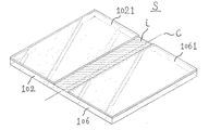
また本発明の別の形態によれば、連続する一枚のシートを折り曲げることで前記第1シートおよび第2シートが構成されてなる。 図8は、この形態を説明するための斜視図である。矩形の一枚のシートSの、長さ方向の中央部分の中心線Cを基準として、該シートSを折り曲げることにより第1シート102および第2シート106が形成される。該シートS上の中心線Cを隔てた両側には積層体が形成された際の第1シート102および第2シート106の夫々に粘着剤1021および粘着剤1061が塗布されている。図9は、該シートSを折り曲げる過程を示すものである。該シートS上の粘着面同士が重ね合わされるように中心線Cを基準に折り曲げるが、粘着面同士が接しないように剥離シート104を設置した上で両者を重ね合わせる必要がある。この形態によれば、上記第5工程において、標本202が固定されている第1シート102の粘着面と、第2シート106の粘着面との重ね合わせの際に、ズレが生じにくくなる。図9に示すとおり、第1シート102および第2シート106が連続している他は、図1に示した積層体と同様に第1シート102、粘着剤1021、剥離シート104、粘着剤1061、第シート106をこの順で備えた積層体である。なお、実際の折り目は鋭角として存在するものであるが、便宜上丸みを帯びた形状で図示した。
According to another aspect of the present invention, the first sheet and the second sheet are formed by bending a continuous sheet. FIG. 8 is a perspective view for explaining this embodiment. The
なお、図8の中心線Cの周囲の斜線部iには、粘着剤を塗布しないことが好ましい。この斜線部iは、第1シート102および第2シート106の折り曲げ部内側であって、この部分に粘着剤が塗布されていると、標本202のサイズが中心線Cに到達する程に大きい場合、もしくは中心線Cに接する場所に標本202を設置したい場合、内側に鋭角に折り曲げられた斜線部iの粘着剤によって、標本202が中心線Cに到達する前に固定されてしまい、不具合が発生する。
In addition, it is preferable not to apply an adhesive to the hatched portion i around the center line C in FIG. The hatched portion i is inside the bent portion of the
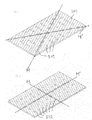
また本発明の別の形態によれば、剥離シートが孔部を有していることが好ましい。図10は、孔部を有する剥離シートを説明するための平面図である。 図10の形態によれば、剥離シート104の複数個所に小さい孔部502が設けられている。この形態によれば、例えば標本202が折れ曲がったり、皺だらけの状態である場合、上記第2工程で、剥離シート104の孔部502を通じて、標本202が第2シート106の粘着面に仮止めされ、標本202が一時的に剥離シート104上に折れ曲がりや皺のない伸ばされた状態で固定される。そうした上で上記第3工程において第1シート102によって標本202を粘着固定させると、当該状態で標本202が固定されることになる。なお、標本202は孔部502を通じて第2シート106の粘着面に仮止めされているだけであるので、上記第4工程では第2シート106の粘着面から容易に分離させることができる。 この形態において、孔部502の合計面積は、剥離シート104の12〜27%を占めるのが好ましい。 また、図10(a)に示すとおり、剥離シート104の対角線MおよびM’に沿って設けられた孔部502は、他の孔部よりも孔部面積を大きくしておくことが好ましい。その理由は、皺が多くて状態の悪い標本を伸ばして剥離シート上に仮固定する際に、標本上の一点から同心円状に仮固定するよりも標本を周囲から引っ張り、引っ張られた状態を維持しながら仮固定したほうが標本の歪みは小さくなる。標本の多くが概ね矩形であると仮定した場合、満遍なく標本の皺を伸ばすためには対角線方向に引っ張ることが最も有効である。標本上の2本の対角線を夫々順次両端から引っ張り、引っ張られた状態を維持したまま対角線付近を優先して強く仮固定することにより歪みが小さくなるとともに、対角線以外の残りの部分の仮固定は軽く行うだけで十分であり従って、対角線上以外の孔部の面積は小さくてよい。 さらに、図10(b)において、剥離シート104の中心線MおよびM’に沿って設けられた孔部502が、他の孔部よりも孔部面積を大きくした形状を示した。この形状は、標本の中心線が明らかな場合の仮固定に際して好ましい。皺が多くて状態の悪い標本の中心線を伸ばして剥離シート上に仮固定する際に、伸ばされた標本の中心線をそのまま剥離シートの中心線上に仮固定することにより、標本の中心線が剥離シート中心線上に固定される。その後に、剥離シート上のもう一方の中心線上に位置する標本を両側から引っ張り、引っ張られた状態を維持したまま剥離シート上に仮固定する。標本を2本の中心線上で仮固定した上で、残りの部分の仮固定は軽く行うだけで十分であり従って、中心線上以外の孔部の面積は小さくてよい。 図10(a)および(b)において夫々、剥離シート104の対角線および中心線に沿って設けられた孔部502を、他の孔部よりも孔部面積を大きくした形状を示したが、孔部面積を大きくする箇所は対角線と中心線に限定されない。標本の形状に応じ様々なパターンが考えられるが、何れにせよ剥離シート上で孔部面積が比較的大きい箇所が線上に分布していることによりその他の部分とのメリハリをつけることが重要となる。皺が多くて状態の悪い標本は、孔部面積が比較的大きい箇所により確実に引き伸ばされるとともに、その他の孔部面積が比較的小さいことにより標本は必要以上に強く仮固定されないため、標本を剥離シートから引き離す際に標本にかかる負担を最小限に留めることが出来る。
Moreover, according to another form of this invention, it is preferable that a peeling sheet has a hole. FIG. 10 is a plan view for explaining a release sheet having a hole. According to the form of FIG. 10,
また本発明の別の形態では、第1シート102および第2シート106により、粘着剤1021、粘着剤1061および剥離シート104が気密に収納されていることが好ましい。 乾燥状態で粘着性を失う恐れのある粘着剤を採用した場合は、第1シート102と第2シート106の周囲を易接着剤等で仮接着しておくことにより、第1シート102と第2シート106で構成される収納部内部が気密状態となり、粘着剤の乾燥を防止することができる。
Moreover, in another form of this invention, it is preferable that the adhesive 1021, the adhesive 1061, and the
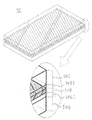
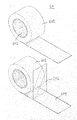
図11は、本発明の積層体のさらに別の形態を説明するための斜視図である。図11(a)において、本発明の積層体60は、長尺状に形成され、芯部601の周囲に巻き回され、巻体602を形成している。図11(b)は、巻体602から一部が巻き出された本発明の積層体において、第1シート102を剥離シート104から分離させた形態の斜視図である。 本発明の積層体60は、剥離シート104に切れ目を設け、複数部分に分割可能としておくことが好ましい。
FIG. 11 is a perspective view for explaining still another embodiment of the laminate of the present invention. In FIG. 11A, the
図12は、剥離シート104に切れ目が設けられている形態を説明するための、本発明の積層体の斜視図である。図12に示すように、本発明の積層体60において、剥離シート104の長さ方向と直交する方向に切れ目dが複数個所設けられている。
FIG. 12 is a perspective view of the laminate of the present invention for explaining a form in which the
以下、剥離シート104に切れ目が設けられ、複数部分に分割可能である場合における、本発明の積層体の使用方法を説明する。なお、下記の使用方法は、上記で説明した本発明の積層体の使用方法の第1工程から第5工程の作業に準じている。
Hereinafter, the usage method of the laminated body of this invention in case a cut | interruption is provided in the
まず、図13に示すように、第1シート102およびその粘着面を形成する粘着剤1021を、剥離シート104から分離させる。 次に、図14に示すように、剥離シート104上の所望の箇所に標本202を設置する。 続いて、図15に示すように、分離した第1シート102を標本202上に載置し、粘着させる。この段階で、第1シート102と標本202とが粘着し、固定された状態となる 次に図16に示すように、第1シート102に設けられた粘着剤1021に固定された標本202を第2シート106から分離させる。 続いて、図17に示すように、剥離シート104を切れ目毎に除去する。なお、剥離シート104に切れ目が設けられていない場合は、剥離シート104が巻体に繋がっているため、この段階で除去できないことになる。 次に図18に示すように、第1シート102の粘着面に固定された標本202を、第2シート106の粘着面と重ね合わせる。 続いて、図19に示すように、長尺状の積層体60を、所望の箇所でカットする。 最後に、図20に示すように、カットした部分の近辺に残存している剥離シート104を、例えば第1シート102を上方に持ち上げて露出することにより除去する。
First, as shown in FIG. 13, the
上記のような形態によれば、積層体を巻体とするために持ち運びや保管に好適となるとともに、第1シート102の分離および再粘着の方向が、巻体からの積層体の巻き出し方向に規制されるため、第1シート102と標本202とが互いにずれることなく第2シート106に粘着し固定されるために好ましい。
According to the above configuration, since the laminate is used as a roll, it is suitable for carrying and storage, and the direction of separation and re-adhesion of the
10 積層体102 第1シート1021 粘着剤(第1シートに塗布)104 剥離シート106 第2シート1061 粘着剤(第2シートに塗布)202 標本
10
Claims (8)
Priority Applications (1)
| Application Number | Priority Date | Filing Date | Title |
|---|---|---|---|
| JP2011000098A JP5139544B2 (en) | 2011-01-04 | 2011-01-04 | Laminated body |
Applications Claiming Priority (1)
| Application Number | Priority Date | Filing Date | Title |
|---|---|---|---|
| JP2011000098A JP5139544B2 (en) | 2011-01-04 | 2011-01-04 | Laminated body |
Publications (2)
| Publication Number | Publication Date |
|---|---|
| JP2012139939A true JP2012139939A (en) | 2012-07-26 |
| JP5139544B2 JP5139544B2 (en) | 2013-02-06 |
Family
ID=46676718
Family Applications (1)
| Application Number | Title | Priority Date | Filing Date |
|---|---|---|---|
| JP2011000098A Expired - Fee Related JP5139544B2 (en) | 2011-01-04 | 2011-01-04 | Laminated body |
Country Status (1)
| Country | Link |
|---|---|
| JP (1) | JP5139544B2 (en) |
Cited By (1)
| Publication number | Priority date | Publication date | Assignee | Title |
|---|---|---|---|---|
| CN111500201A (en) * | 2019-01-30 | 2020-08-07 | 南亚塑胶工业股份有限公司 | OCA optical cement and manufacturing method thereof |
Citations (7)
| Publication number | Priority date | Publication date | Assignee | Title |
|---|---|---|---|---|
| JPS54136936A (en) * | 1978-04-14 | 1979-10-24 | Nichiban Kk | Adhesive piece |
| JPS62137083U (en) * | 1986-02-21 | 1987-08-28 | ||
| JPS63124173U (en) * | 1987-02-03 | 1988-08-12 | ||
| JPH02233299A (en) * | 1989-03-08 | 1990-09-14 | Dow Kako Kk | Adhesive panel |
| JPH0314402A (en) * | 1989-06-12 | 1991-01-23 | Nippon Hikari Fiber Kk | Packing |
| JP3030671U (en) * | 1996-04-26 | 1996-11-01 | 清治 石戸 | Transparent protective resin film for passbooks, insurance cards, etc. |
| JP2004230575A (en) * | 2003-01-28 | 2004-08-19 | Abe Shiko:Kk | Card with frame, loose-leaf and photograph stand for individual vacuum filing of photograph or the like |
-
2011
- 2011-01-04 JP JP2011000098A patent/JP5139544B2/en not_active Expired - Fee Related
Patent Citations (7)
| Publication number | Priority date | Publication date | Assignee | Title |
|---|---|---|---|---|
| JPS54136936A (en) * | 1978-04-14 | 1979-10-24 | Nichiban Kk | Adhesive piece |
| JPS62137083U (en) * | 1986-02-21 | 1987-08-28 | ||
| JPS63124173U (en) * | 1987-02-03 | 1988-08-12 | ||
| JPH02233299A (en) * | 1989-03-08 | 1990-09-14 | Dow Kako Kk | Adhesive panel |
| JPH0314402A (en) * | 1989-06-12 | 1991-01-23 | Nippon Hikari Fiber Kk | Packing |
| JP3030671U (en) * | 1996-04-26 | 1996-11-01 | 清治 石戸 | Transparent protective resin film for passbooks, insurance cards, etc. |
| JP2004230575A (en) * | 2003-01-28 | 2004-08-19 | Abe Shiko:Kk | Card with frame, loose-leaf and photograph stand for individual vacuum filing of photograph or the like |
Cited By (2)
| Publication number | Priority date | Publication date | Assignee | Title |
|---|---|---|---|---|
| CN111500201A (en) * | 2019-01-30 | 2020-08-07 | 南亚塑胶工业股份有限公司 | OCA optical cement and manufacturing method thereof |
| CN111500201B (en) * | 2019-01-30 | 2023-02-28 | 南亚塑胶工业股份有限公司 | OCA optical cement and manufacturing method thereof |
Also Published As
| Publication number | Publication date |
|---|---|
| JP5139544B2 (en) | 2013-02-06 |
Similar Documents
| Publication | Publication Date | Title |
|---|---|---|
| US20200235771A1 (en) | Protective covers for electronic devices | |
| US9346251B2 (en) | Protective adhesive film product | |
| US10364374B2 (en) | Dry apply protective methods | |
| JP4326635B2 (en) | Glass film handling method and glass laminate | |
| JP3124275U (en) | Monitor protective sheet | |
| JP4874383B2 (en) | A ventilation filter, a method for fixing the ventilation filter, and a method for manufacturing an electric device. | |
| US20160043765A1 (en) | Protective film composite | |
| JP2012533454A5 (en) | ||
| JP2019032415A5 (en) | ||
| JP5139544B2 (en) | Laminated body | |
| JP5737625B2 (en) | GLASS FILM LAMINATE, GLASS FILM LAMINATE ROLL, GLASS FILTER GLASS FILM LAMINATE AND GLASS FILM LAMINATE PROCESS | |
| JP7374821B2 (en) | Optical laminated film manufacturing device and optical laminated film manufacturing method | |
| JP2011178032A (en) | Laminate | |
| JPH0538348A (en) | Adhesive sheet | |
| JP2012061171A (en) | Dressing material | |
| JP6236718B2 (en) | Composite layer structure for transfer | |
| KR20110107164A (en) | Battery pack label sticker sheet, manufacturing method thereof and method for attaching label sticker onto battery pack | |
| JP5951176B2 (en) | Dressing material | |
| TW201540515A (en) | Film adhering device, method of adhering film, and laminated film | |
| JP3199420U (en) | Dressing material | |
| JP2010042922A (en) | Device and system for peeling protecting film | |
| JP2008081190A (en) | Packaging material for optical sheet, optical-sheet packaging body, and pressure-sensitive adhesive tape for sealing packaging material | |
| JP3332506B2 (en) | Cellular retroreflective sheet | |
| JP2576891Y2 (en) | Stacked postcard sheets | |
| TWM477378U (en) | Protective films laminating device |
Legal Events
| Date | Code | Title | Description |
|---|---|---|---|
| A871 | Explanation of circumstances concerning accelerated examination |
Free format text: JAPANESE INTERMEDIATE CODE: A871 Effective date: 20120517 |
|
| A975 | Report on accelerated examination |
Free format text: JAPANESE INTERMEDIATE CODE: A971005 Effective date: 20120629 |
|
| A131 | Notification of reasons for refusal |
Free format text: JAPANESE INTERMEDIATE CODE: A131 Effective date: 20120705 |
|
| A521 | Written amendment |
Free format text: JAPANESE INTERMEDIATE CODE: A523 Effective date: 20120825 |
|
| TRDD | Decision of grant or rejection written | ||
| A01 | Written decision to grant a patent or to grant a registration (utility model) |
Free format text: JAPANESE INTERMEDIATE CODE: A01 Effective date: 20121023 |
|
| A01 | Written decision to grant a patent or to grant a registration (utility model) |
Free format text: JAPANESE INTERMEDIATE CODE: A01 |
|
| R150 | Certificate of patent or registration of utility model |
Free format text: JAPANESE INTERMEDIATE CODE: R150 |
|
| FPAY | Renewal fee payment (event date is renewal date of database) |
Free format text: PAYMENT UNTIL: 20151122 |
|
| R154 | Certificate of patent or utility model (reissue) |
Free format text: JAPANESE INTERMEDIATE CODE: R154 |
|
| FPAY | Renewal fee payment (event date is renewal date of database) |
Free format text: PAYMENT UNTIL: 20151122 Year of fee payment: 3 |
|
| R150 | Certificate of patent or registration of utility model |
Free format text: JAPANESE INTERMEDIATE CODE: R150 |
|
| R250 | Receipt of annual fees |
Free format text: JAPANESE INTERMEDIATE CODE: R250 |
|
| LAPS | Cancellation because of no payment of annual fees |