JP2012139286A - Blood pressure measuring apparatus - Google Patents
Blood pressure measuring apparatus Download PDFInfo
- Publication number
- JP2012139286A JP2012139286A JP2010292742A JP2010292742A JP2012139286A JP 2012139286 A JP2012139286 A JP 2012139286A JP 2010292742 A JP2010292742 A JP 2010292742A JP 2010292742 A JP2010292742 A JP 2010292742A JP 2012139286 A JP2012139286 A JP 2012139286A
- Authority
- JP
- Japan
- Prior art keywords
- pressure
- pressure sensor
- blood pressure
- pressure sensors
- blood
- Prior art date
- Legal status (The legal status is an assumption and is not a legal conclusion. Google has not performed a legal analysis and makes no representation as to the accuracy of the status listed.)
- Withdrawn
Links
Images


Classifications
-
- A—HUMAN NECESSITIES
- A61—MEDICAL OR VETERINARY SCIENCE; HYGIENE
- A61B—DIAGNOSIS; SURGERY; IDENTIFICATION
- A61B5/00—Measuring for diagnostic purposes; Identification of persons
- A61B5/72—Signal processing specially adapted for physiological signals or for diagnostic purposes
- A61B5/7221—Determining signal validity, reliability or quality
-
- A—HUMAN NECESSITIES
- A61—MEDICAL OR VETERINARY SCIENCE; HYGIENE
- A61B—DIAGNOSIS; SURGERY; IDENTIFICATION
- A61B5/00—Measuring for diagnostic purposes; Identification of persons
- A61B5/02—Detecting, measuring or recording pulse, heart rate, blood pressure or blood flow; Combined pulse/heart-rate/blood pressure determination; Evaluating a cardiovascular condition not otherwise provided for, e.g. using combinations of techniques provided for in this group with electrocardiography or electroauscultation; Heart catheters for measuring blood pressure
- A61B5/021—Measuring pressure in heart or blood vessels
- A61B5/022—Measuring pressure in heart or blood vessels by applying pressure to close blood vessels, e.g. against the skin; Ophthalmodynamometers
-
- A—HUMAN NECESSITIES
- A61—MEDICAL OR VETERINARY SCIENCE; HYGIENE
- A61B—DIAGNOSIS; SURGERY; IDENTIFICATION
- A61B2562/00—Details of sensors; Constructional details of sensor housings or probes; Accessories for sensors
- A61B2562/02—Details of sensors specially adapted for in-vivo measurements
- A61B2562/0209—Special features of electrodes classified in A61B5/24, A61B5/25, A61B5/283, A61B5/291, A61B5/296, A61B5/053
- A61B2562/0214—Capacitive electrodes
Landscapes
- Health & Medical Sciences (AREA)
- Life Sciences & Earth Sciences (AREA)
- Engineering & Computer Science (AREA)
- Public Health (AREA)
- Molecular Biology (AREA)
- Cardiology (AREA)
- Vascular Medicine (AREA)
- Physics & Mathematics (AREA)
- Veterinary Medicine (AREA)
- Biophysics (AREA)
- Pathology (AREA)
- Biomedical Technology (AREA)
- Heart & Thoracic Surgery (AREA)
- Medical Informatics (AREA)
- Physiology (AREA)
- Surgery (AREA)
- Animal Behavior & Ethology (AREA)
- General Health & Medical Sciences (AREA)
- Artificial Intelligence (AREA)
- Computer Vision & Pattern Recognition (AREA)
- Ophthalmology & Optometry (AREA)
- Signal Processing (AREA)
- Psychiatry (AREA)
- Measuring Pulse, Heart Rate, Blood Pressure Or Blood Flow (AREA)
Abstract
Description
本発明は、血圧測定装置に関し、特に、血圧測定の際に測定部位に空気袋を巻き付けて圧迫する血圧測定装置に関する。 The present invention relates to a blood pressure measurement device, and more particularly, to a blood pressure measurement device that wraps an air bag around a measurement site and compresses the blood pressure measurement.
従来から、血圧測定装置では、血圧の測定のためのセンサを搭載し、当該センサの出力値に基づいて血圧が測定されていた。このような血圧測定装置では、血圧を正確に測定するために、センサに不具合が生じた場合、そのことを確実に検出する必要がある。 Conventionally, blood pressure measuring devices are equipped with a sensor for measuring blood pressure, and blood pressure is measured based on the output value of the sensor. In such a blood pressure measurement device, in order to accurately measure blood pressure, it is necessary to reliably detect when a malfunction occurs in the sensor.
このような観点から、特許文献1(特開平2−19133号公報)には、センサとして圧力センサが採用される血圧計装置において、複数の圧力センサを搭載し、これらの検出値を比較することによって、圧力センサの不具合を検出する技術が開示されている。 From this point of view, Patent Document 1 (Japanese Patent Application Laid-Open No. 2-19133) discloses a sphygmomanometer that employs a pressure sensor as a sensor, and a plurality of pressure sensors are mounted and their detected values are compared. Discloses a technique for detecting a malfunction of a pressure sensor.
しかしながら、特許文献1に記載の技術によれば、複数の圧力センサの少なくとも双方に不具合が生じた場合、これら複数の圧力センサの検出値を比較しても、当該双方に不具合が生じていることを検出することができない事態が想定される。具体的には、たとえば複数の圧力センサによって測定される圧力値が等しい場合やそれらの差が所定の量を超えない限り双方の圧力センサに不具合が生じていないと判断されるところ、双方の圧力センサに同様の不具合が生じていた場合にも、それらの圧力値が等しいかそれらの差が所定の量を超えないときがあるため、このような場合、不具合が生じていることを検出できない。この点に関し、特許文献1では、電源電圧等の他の値を参照して、圧力センサの不具合による最悪の事態に備えている。
However, according to the technique described in
本発明は、かかる実情に鑑み考え出されたものであり、その目的は、血圧測定装置において、血圧測定のためのセンサの不具合を確実に検出することである。 The present invention has been conceived in view of such circumstances, and an object thereof is to reliably detect a malfunction of a sensor for blood pressure measurement in the blood pressure measurement device.
本発明に従った血圧測定装置は、巻付けられることにより測定部位を圧迫するカフと、カフ内の圧力を検出する複数の圧力センサと、圧力センサの検出出力に基づいて血圧の指標についての値を決定する決定部とを備え、圧力センサは、重力がカフ内の圧力の検出に及ぼす影響が互いに異なる状態で設けられており、複数の圧力センサの検出出力が、重力によって及ぼされる影響の違いによって想定される範囲内であるか否かを判断することにより、複数の圧力センサの少なくとも一方が異常であるか否かを判断する判断部をさらに備える。 The blood pressure measurement device according to the present invention includes a cuff that presses a measurement site by being wound, a plurality of pressure sensors that detect pressure in the cuff, and a value for a blood pressure index based on a detection output of the pressure sensor. The pressure sensor is provided in a state where the influence of gravity on the detection of the pressure in the cuff is different from each other, and the detection output of the plurality of pressure sensors is different in the influence exerted by the gravity. Is further provided with a determination unit that determines whether or not at least one of the plurality of pressure sensors is abnormal.
また、本発明の血圧測定装置では、各圧力センサは、カフ内の圧力の変化に基づいて変位する面を有し、複数の圧力センサは、面の圧力変化に対する変位の向きが互いに異なるように設けられていることが好ましい。 In the blood pressure measurement device of the present invention, each pressure sensor has a surface that is displaced based on a change in pressure in the cuff, and the plurality of pressure sensors have different displacement directions with respect to the pressure change of the surface. It is preferable to be provided.
また、本発明の血圧測定装置では、複数の圧力センサは、面が互いに180度の角度をなす、2個の圧力センサを含むことが好ましい。 In the blood pressure measurement device of the present invention, it is preferable that the plurality of pressure sensors include two pressure sensors whose surfaces form an angle of 180 degrees with each other.
また、本発明の血圧測定装置では、複数の圧力センサは、面が互いに90度の角度をなす、2個の圧力センサを含むことが好ましい。 In the blood pressure measurement device of the present invention, it is preferable that the plurality of pressure sensors include two pressure sensors whose surfaces form an angle of 90 degrees with each other.
また、本発明の血圧測定装置では、各圧力センサは、カフ内の圧力の変化に基づいて変位する面を有し、複数の圧力センサは、面の鉛直方向の高さが異なるように設けられた2個の圧力センサを含むことが好ましい。 In the blood pressure measurement device of the present invention, each pressure sensor has a surface that is displaced based on a change in pressure in the cuff, and the plurality of pressure sensors are provided so that the heights of the surfaces in the vertical direction are different. Preferably, it includes only two pressure sensors.
本発明によれば、複数の圧力センサの検出出力において、これらに対して重力が及ぼす影響の違いによって想定される範囲の差が見られるか否かによって、当該圧力センサの不具合の有無が判断される。 According to the present invention, in the detection outputs of the plurality of pressure sensors, whether or not there is a malfunction of the pressure sensor is determined based on whether or not there is a difference in the range assumed due to the difference in the influence of gravity on these. The
これにより、たとえ複数の圧力センサの双方に同様の不具合が生じたとしても、これらの出力は、重力により互いに異なる影響を受けるため、これらの検出出力は正確に重力による影響の差異を反映したものとはならないと考えられる。したがって、このような場合でも、確実に不具合の発生を検出できる。 As a result, even if the same failure occurs in both of the multiple pressure sensors, these outputs are affected differently by gravity, so these detection outputs accurately reflect the difference in the effects of gravity. It is not considered to be. Therefore, even in such a case, the occurrence of a failure can be detected reliably.
以下に、図面を参照しつつ、本発明の実施の形態について説明する。以下の説明では、同一の部品および構成要素には同一の符号を付してある。それらの名称および機能も同じである。 Embodiments of the present invention will be described below with reference to the drawings. In the following description, the same parts and components are denoted by the same reference numerals. Their names and functions are also the same.
[1.全体構成]
図1は、本発明の一実施の形態にかかる血圧測定装置(以下、血圧計)100の外観の具体例を示す斜視図である。
[1. overall structure]
FIG. 1 is a perspective view showing a specific example of the appearance of a blood pressure measurement device (hereinafter referred to as a sphygmomanometer) 100 according to an embodiment of the present invention.
図1を参照して、本実施の形態にかかる血圧計100は、主に、机等に載置される本体100Aと、測定者の測定部位である上腕を差込むための測定部170とを備える。本体100Aの上部には、電源スイッチや測定スイッチなどが配置された操作部190と、表示部180と、肘置きとが備えられる。また、測定部170は本体100Aに対して角度が可変に取付けられており、略円筒状の機枠であるハウジング160と、ハウジング160の内周部に収納された生体圧迫固定装置とを備える。
Referring to FIG. 1,
図1に示されるように、通常の使用状態においてハウジング160の内周部に収納された生体圧迫固定装置は露出しておらず、カバーによって覆われている。表示部180は、たとえば液晶ディスプレイ等の周知の表示装置によって実現される。
As shown in FIG. 1, the living body pressure fixing device housed in the inner peripheral portion of the
図2は、血圧測定時の血圧計100の断面概略図である。図2を参照して、被測定者は、血圧測定の際には、ハウジング160の内部に上腕を差込んで上記肘置きに肘を載置して、測定開始を指示する。上腕は上記生体圧迫固定装置によって圧迫固定され、血圧が測定される。生体圧迫固定装置は、カフ150を含む、カフ150は、測定部位を圧迫して血圧を測定するための測定用流体袋である空気袋151を内包する。
FIG. 2 is a schematic cross-sectional view of the
[2.ブロック構成]
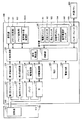
図3は、血圧計100のブロック図である。
[2. Block configuration]
FIG. 3 is a block diagram of the
図3を参照して、血圧計100は、血圧計100内の各要素を集中的に制御および監視する中央処理部110を含む。中央処理部110は、CPU(Central Processing Unit)を含む。また、中央処理部110は、その機能として、血圧算出部111と、判断部112を含む。血圧算出部111および判断部112は、上記CPUが所定のプログラムを実行することによって実現されても良いし、LSI(Large Scale Integration)等の回路としてハードウェア的に実現されても良い。
Referring to FIG. 3,
また、血圧計100の本体100Aの内部には、空気袋151に空気を供給または排出する血圧測定用エア系コンポーネントが設けられている。当該血圧測定用エア系コンポーネントは、エア管140を介して、空気袋151に空気を供給し、また、空気袋151から空気を排出する。血圧測定用エア系コンポーネントは、空気袋151内の圧力を検出する第1圧力センサ131および第2圧力センサ132、空気袋151を膨縮させるためのポンプ134、ならびに、弁135を含む。本実施の形態では、第1圧力センサ131および第2圧力センサ132は静電容量型の圧力センサであり、空気袋151の内圧変化により容量値が変化する。本体100Aの内部には、第1圧力センサ131および第2圧力センサ132の容量値に応じた発振周波数の信号を発生する第1発振回路121および第2発振回路122と、ポンプ134を駆動するポンプ駆動回路124と、弁135を駆動する弁駆動回路125とが設けられる。
Further, an air system component for blood pressure measurement for supplying or discharging air to / from the
空気袋151の内圧変化に応じた第1発振回路121および第2発振回路122から出力される発振周波数の信号が中央処理部110(血圧算出部111)において適宜処理されることにより、血圧計100では、被測定者の血圧や脈拍が測定される。
A signal of the oscillation frequency output from the
また、血圧計100は、中央処理部110のワークエリアとなるメモリ181と、中央処理部110に所定の動作をさせるプログラムや測定された血圧値などの各種情報を記憶するメモリ182と、測定等のための各種指示を入力するために操作される操作部190と、計時機能を有する時計183とを含む。
The
操作部190は、血圧計100への電源の投入の入/切を切換える電源スイッチ191と、血圧計100に対して血圧測定を開始させる際に操作される測定スイッチ192と、実行中の血圧測定動作を停止させるために操作される停止スイッチ193と、メモリ182に記憶された血圧値や脈拍数等のデータを表示部180に表示させるために操作される記録呼び出しスイッチ194と、血圧計100の被測定者を選択する使用者選択スイッチ195とを含む。
The
また、中央処理部110は、フロッピー(登録商標)ディスクやUSB(Universal Serial Bus)メモリ、SDメモリカード等の、本体100Aに対して着脱可能な外部メモリ900に対して情報の読み込みおよび書き込みができる。そして、血圧計100は、外部メモリ900に対する読み込み/書き込みの処理をするためのインターフェース185を含む。
The
また、血圧計100は、血圧計100内の各要素に電力を供給する電源回路184を含む。
The
メモリ182は、後述する基準差分値を記憶する基準差分値記憶部182Aを含む。また、メモリ182には、ユーザの、血液に関する測定記録データが記憶されている。当該測定データの一例を、図4に示す。
The
図4を参照して、測定記録データでは、各測定データの組を特定する情報であるID601と、使用者ごとの名称を示す使用者602と、各データが測定された日時を示す測定日時603と、測定データの組(最高血圧値、最低血圧値、脈拍数)を示す血圧値・測定値604とが互いに関連付けられている。当該測定記録データを参照することにより、血圧計100は、使用者ごとに、測定記録データの履歴を管理できる。
Referring to FIG. 4, in the measurement record data, an
[3.圧力センサの構成]
以下、第1圧力センサ131の構成を説明する。なお、第2圧力センサ132の構成は、第1圧力センサ131と同様のものとすることができる。
[3. Configuration of pressure sensor]
Hereinafter, the configuration of the
図5(A)および図5(B)に、第1圧力センサ131の斜視図を示す。また、図6に、第1圧力センサ131の分解斜視図を示す。また、図7に、第1圧力センサ131の模式的な断面図を示す。図7では、図6に記載された一部の部品の図示が省略されている。
5A and 5B are perspective views of the
図5(A)、図5(B)、図6、および、図7を参照して、第1圧力センサ131は、第1ベース308と、第1ベース308上にはめ込まれた第2ベース307と、第2ベース307上に載置されたダイヤフラム306と、ダイヤフラム306上に配置された可動電極304と、可動電極304上に配置された固定電極303とを含む。ダイヤフラム306と可動電極304はハンダ付けによって接合されている。固定電極303は、定常状態(圧力が印加されていない状態)では可動電極304に対して離間するように、ネジ302によって第1ベース308にネジ止めされている。固定電極303上には、キャップ301が設けられている。キャップ301は、第1ベース308とともに第1圧力センサ131の外郭を覆うように、固定電極303等の上部から第1ベース308に対してはめ込まれている。
5A, 5B, 6 and 7, the
第1ベース308の中央近傍には、孔308Aが形成されている。第1ベース308の下部には、管部308Bが形成されている。孔308Aは、管部308Bの下端まで貫通している。
A
管部308Bは、エア管140によって、空気袋151に連結されている。空気袋151内に圧力値の変動が生じると、当該圧力値の変動は、エア管140を介して、第1圧力センサ131へと伝えられる。図7では、圧力が伝えられる方向が矢印A1で示されている。当該圧力値の変動により、ダイヤフラム306の、矢印A1方向の伸縮の度合いが変動する。
The
可動電極304と固定電極303は、それぞれ、矢印A1方向に交わる面304A,303Aを有する。面304Aは、空気袋151内の圧力の変化により変位する面である。
The
ダイヤフラム306は、蛇腹構造を有しており、空気袋151内の圧力の変化に応じて矢印A1方向の伸縮の度合いが変動する。そして、空気袋151内の圧力の変化に応じた、ダイヤフラム306の上記伸縮の度合いの変動により、面304Aの矢印A1方向の位置が変動する。これにより、矢印A1方向の面303Aに対する面304Aの距離が変動する。これにより、第1圧力センサ131の静電容量が変動する。血圧計100では、第1圧力センサ131の静電容量値の変化に基づいて、空気袋151内の圧力値を検出する。なお、メモリ181には、第1圧力センサ131の静電容量値を空気袋151内の圧力値に変換するための情報が記憶されている。
第2圧力センサ132も、第1圧力センサと同様の構成を有し、そして、エア管140によって、空気袋151に連結されている。第2圧力センサ132においても、第1圧力センサ131と同様に、空気袋151内の圧力値の変動に応じて、可動電極と固定電極の距離が変動し、これにより、第2圧力センサ132の静電容量値が変化する。血圧計100では、第2圧力センサ132の静電容量値の変化に基づいて、空気袋151内の圧力値を検出することができる。
The
[4.複数の圧力センサの、配置と検出出力]
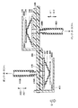
図8および図9は、血圧計100における、第1圧力センサ131と第2圧力センサ132の配置を説明するための図である。図9の第2圧力センサ132は、第1圧力センサ131と同様に、第1ベース408と、第2ベース407と、ダイヤフラム406と、可動電極404と、固定電極403とを含む。可動電極404は、面404Aを有する。固定電極403は、面403Aを有する。面404A,403Aは、可動電極304の面304A,固定電極303の面303Aにそれぞれ相当する。第1ベース408は、第1ベース308と同様に、孔308Aに相当する孔408Bを有し、また、管部408Bを有する。
[4. Arrangement and detection output of multiple pressure sensors]
8 and 9 are diagrams for explaining the arrangement of the
図8および図9を参照して、本体100Aの内部には、種々の部品が実装される基板200が設けられている。本実施の形態では、基板200には、その上面から管部308Bを貫通させるように第1圧力センサ131が実装され、その下面から管部408Bを貫通させるように第2圧力センサ132が実装されている。管部308Bは、エア管140Aに連結されている。管部408Bは、エア管140Bに連結されている。エア管140Aとエア管140Bは、いずれもエア管140から分岐されたものであり、空気袋151内部に連結されている。
With reference to FIG. 8 and FIG. 9, a
矢印A11,A12、A21,A22は、それぞれ、空気袋151内部の圧力が変動した際に、ダイヤフラム306,406が変位する方向、および、当該ダイヤフラム306,406の変位に応じて可動電極304,404が変位する向きを示す。具体的には、空気袋151内の圧力が上昇すると、ダイヤフラム306は矢印A11の向きに力を受け、当該向きに変位する。これにより、面304Aは、矢印A11の向きに変位し、面303Aに近づく。また、空気袋151内の圧力が上昇すると、ダイヤフラム406は矢印A21の向きに力を受け、当該向きに変位する。これにより、面404Aは、矢印A21の向きに変位し、面403Aに近づく。
Arrows A11, A12, A21, and A22 indicate the
一方、空気袋151内の圧力が減少すると、ダイヤフラム306は矢印A12の向きに力を受け、当該向きに変位する。これにより、面304Aは、矢印A12の向きに変位し、面303Aから遠ざかる。また、空気袋151内の圧力が減少すると、ダイヤフラム406は矢印A22の向きに力を受け、当該向きに変位する。これにより、面404Aは、矢印A22の向きに変位し、面403Aから遠ざかる。
On the other hand, when the pressure in the
矢印Gは、重力の向きを示す。そして、上記したダイヤフラム306,406の変位量および面304A,404Aの変位量は、実際には、空気袋151内の圧力の変化量に加え、重力の影響を受ける。
Arrow G indicates the direction of gravity. The displacement amounts of the
空気袋151内の圧力がある一定量増加した場合、ダイヤフラム406の矢印A21向きの変位量および面404Aの矢印A21の向きの変位量は、ダイヤフラム306の矢印A11向きの変位量および面304Aの矢印A11の向きの変位量よりも大きくなる。矢印A21は、ダイヤフラム406および可動電極404の自重がかかる向きであるのに対し、矢印A11は、ダイヤフラム306および可動電極304の自重に逆らう向きだからである。
When the pressure in the
空気袋151内の圧力がある一定量減少した場合、ダイヤフラム306の矢印A12向きの変位量および面304Aの矢印A12の向きの変位量は、ダイヤフラム406の矢印A22向きの変位量および面404Aの矢印A22の向きの変位量よりも大きくなる。矢印A12は、ダイヤフラム306および可動電極304の自重がかかる向きであるのに対し、矢印A22は、ダイヤフラム406および可動電極404の自重に逆らう向きだからである。
When the pressure in the
[5.圧力センサの検出出力]
図10は、空気袋151内の圧力が変化した際の、第1圧力センサ131および第2圧力センサ132の静電容量の変化の一例を示す。なお、図10では、線LA1および線LA2は、第1圧力センサ131の静電容量の変化を示し、線LB1および線LB2は、第2圧力センサ132の静電容量の変化を示す。また、線LA1および線LB1は、血圧計100の使用開始時の静電容量の変化を示し、線LA2および線LB2は、血圧計100を所定時間使用した後の静電容量の変化を示す。
[5. Pressure sensor detection output]
FIG. 10 shows an example of changes in capacitance of the
図10から理解されるように、血圧計100では、空気袋151の圧力が上昇すると、第1圧力センサ131および第2圧力センサ132の静電容量は低下する。第1圧力センサ131の静電容量の方が、第2圧力センサ132の静電容量よりも、空気袋151内の圧力の上昇に応じた静電容量の低下の度合いが低くなっている。このような、変化の度合いの差異は、図9を参照して説明した、第1圧力センサ131と第2圧力センサ132の、本体100A内の設置の仕方の差異による、ダイヤフラム306,406および可動電極304,404の変位に対する自重のかかり方の差異に基づく。
As understood from FIG. 10, in the
線LA2および線LB2は、使用開始時より時間を経た時点での第1圧力センサ131および第2圧力センサ132の空気袋151内の圧力変化にともなう静電容量変化を示したものである。周囲気温などの環境要素により静電容量の絶対値が変化するため、この例では使用開始時より静電容量が全体的に低い値にオフセットされている。この環境要素による静電容量の変化を補正するため、血圧計の初期化時にこのオフセット量を補正することになる。
Lines LA <b> 2 and LB <b> 2 indicate changes in capacitance due to changes in pressure in the
ここで、空気袋151内の圧力が0mmHgでの第1圧力センサ131の静電容量と第2圧力センサ132の静電容量を比較する。使用開始時における空気袋151内の圧力が0mmHgでの第1圧力センサ131、第2圧力センサの静電容量132をそれぞれC0_N、C0_Pとし、使用開始時より時間を経た時点における空気袋151内の圧力が0mmHgでの第1圧力センサ131、第2圧力センサの静電容量132をそれぞれC1_N、C1_Pとし、各々の差ΔC0、ΔC1とする。
Here, the capacitance of the
本実施の形態では、第1圧力センサ131と第2圧力センサ132の静電容量値の差△C1と使用開始時の差△C0を比較し、△C1と△C0の差が所定の閾値(後述するTH)を超えた場合には、血圧計100は、ダイヤフラム306,406および可動電極304,404が劣化等により異常状態になっていると判断して、その旨を報知する。なお、THは、上記した基準差分値に相当し、基準差分値記憶部182Aに記憶されている。また、△C0も、工場出荷時等に、メモリ182に記憶されている。
In the present embodiment, the difference ΔC1 between the capacitance values of the
[6.血圧測定処理]
図11は、血圧計100において測定者の血圧を測定する際に実行される処理(血圧測定処理)のフローチャートである。
[6. Blood pressure measurement process]
FIG. 11 is a flowchart of a process (blood pressure measurement process) executed when measuring the blood pressure of the measurer with the
図11を参照して、電源スイッチ191を操作されると(ステップST1)、中央処理部110は、ステップST2で血圧計100の初期化を行ない、そして、ステップST3で、圧力センサ状態検出処理を実行する。
Referring to FIG. 11, when
図12は、圧力センサ状態検出処理のサブルーチンのフローチャートである。図12を参照して、当該処理では、中央処理部110は、まずステップST101で、その時点での第1圧力センサ131の静電容量値(C1_N)と第2圧力センサ132の静電容量値(C1_P)を取得して、ステップST102へ処理を進める。
FIG. 12 is a flowchart of a subroutine of pressure sensor state detection processing. Referring to FIG. 12, in this process, first,
ステップST102では、中央処理部110は、次の式(1)に基づき、上記のC1_NとC1_Pの差△C1を算出する。
In step ST102, the
△C1=C1_P−C1_N …(1)
そして、ステップST103で、中央処理部110は、ステップST102で算出した△C1とメモリ182に記憶された△C0の差を算出し、当該差が、閾値(基準差分値記憶部182Aに記憶された基準差分値TH)以下である場合には、ステップST104へ処理を進め、閾値を超える場合には、ステップST105へ処理を進める。
ΔC1 = C1_P−C1_N (1)
In step ST103, the
ステップST104では、中央処理部110は、第1圧力センサ131および第2圧力センサ132が正常であるとして、処理を図11へリターンさせる。
In step ST104, the
一方、ステップST105では、中央処理部110は、第1圧力センサ131と第2圧力センサ132の少なくとも一方が異常であるとして、処理を図11へリターンさせる。
On the other hand, in step ST105, the
図11へ戻って、ステップST3で圧力センサ状態検出処理を実行した後、中央処理部110は、ステップST4で、ステップST3で検出した第1圧力センサ131および第2圧力センサ132の状態を表示部180に表示させて、ステップST5へ処理を進める。図13(A)および図13(B)に、ステップST4における表示部180の表示例を示す。
Returning to FIG. 11, after performing the pressure sensor state detection process in step ST3, the
図13(A)は、ステップST105でセンサが異常であると判断されたときの表示画面500を示し、図13(B)は、ステップST104でセンサが正常であると判断されたときの表示画面510を示す。
FIG. 13A shows a
図13(B)の表示画面510では、第1圧力センサ131および第2圧力センサ132の状態(GOOD)を表す文字列511、空気袋151内の現在の圧力、現在の日時515が示されている。
In the
図13(A)の表示画面500では、現在の日時および空気袋の現在の圧力とともに、第1圧力センサ131および第2圧力センサ132の状態(NG)を表す文字列501が示されている。
In the
図11に戻って、ステップST5では、中央処理部110は、ステップST3における圧力センサ状態検出処理において判断された第1圧力センサ131および第2圧力センサ132の状態が正常であったか異常であったかによって、次に実行する処理を決定する。正常であった場合には、ステップST6へ処理を進め、異常であった場合には、ステップST4での表示を行なったまま、血圧測定処理を終了させる。これにより、血圧計100は、第1圧力センサ131および第2圧力センサ132の異常を表示部180に表示させ、血圧等の測定を行なわない。
Returning to FIG. 11, in step ST5, the
ステップST6では、中央処理部110は、使用者選択スイッチ195に対する被測定者の操作を受け付ける。当該操作は、たとえば、血圧計100に対して、これから血圧等の測定をする者を特定する情報を入力する操作である。
In step ST <b> 6, the
ステップST7では、中央処理部110は、測定スイッチ192に対する被測定者の操作を受け付ける。
In step ST <b> 7, the
次に、ステップST8で、中央処理部110は、カフ(空気袋151)を加圧する。当該加圧は、ステップST9で空気袋151内の圧力が所定の圧力に到達するまで継続され、所定の圧力に到達したと判断すると、ステップST10へ処理を進める。
Next, in step ST8, the
ステップST10では、カフ(空気袋151)の減圧を開始し、ステップST11へ処理を進める。 In step ST10, pressure reduction of the cuff (air bag 151) is started, and the process proceeds to step ST11.
ステップST11では、中央処理部110は、減圧中の第1圧力センサ131および/または第2圧力センサ132の圧力値に基づいて被測定者の血圧を算出する。当該血圧の算出は、ステップST12で被測定者の血圧値が決定できたと判断するまで継続され、血圧値を決定できたと判断すると、ステップST13へ処理を進める。
In step ST11, the
ステップST13では、ステップST12で決定した血圧値を、たとえば図13(C)の表示画面510のように、表示部180に表示させて、ステップST14へ処理を進める。なお、図13(C)の表示画面520では、現在の被測定者の最高血圧値512と、最低血圧値513と、脈拍数514と、現在の日時515が示されている。ここで、後述するステップST12において今回の測定値が決定されるまでは、最高血圧値512と最低血圧値513と脈拍数514は表示されなくても良いし、または、現在の被測定者の前回の測定値が表示されても良い。なお、前回の測定値が表示される場合には、表示されている測定値が今回の測定のものではなく前回の測定のものであることを注意喚起する表示が合わせて表示されることが好ましい。
In step ST13, the blood pressure value determined in step ST12 is displayed on
ステップST14では、ステップST12で決定した血圧値を、図4に示したように、被測定者や測定時の日時に関連付けてメモリ182に記録して、血圧測定処理を終了させる。
In step ST14, as shown in FIG. 4, the blood pressure value determined in step ST12 is recorded in the
以上説明した本実施の形態では、複数の検出用素子(第1圧力センサ131と第2圧力センサ132)が、それらの検出出力に対して重力の及ぼす影響が互いに異なる態様で設置されている。そして、重力の及ぼす影響の違いによって想定される範囲内(基準差分値TH)であるか否かに基づいて、上記複数の検出用素子の少なくとも一方が異常であるか否かが判断される。
In the present embodiment described above, a plurality of detection elements (the
[7.変形例(1)]
以上説明した本実施の形態では、複数の圧力センサ(第1圧力センサ131および第2圧力センサ132)が、図9を主に参照して説明したように、空気袋151内の圧力変化を受ける面の配置が互いに異なる態様で設置されている。これらの圧力センサでは、図10を主に参照して説明したように、空気袋151内の圧力に応じて、静電容量値が変化する。そして、これらの圧力センサにおける静電容量値の差(△C1)と、使用開始時の差(△C0)との差分を算出し(△C1−△C0)、当該差分が閾値を超えた場合には、複数の圧力センサの中の少なくとも1つが異常であるとして、その旨を報知して、血圧測定を行なわない。
[7. Modification (1)]
In the present embodiment described above, the plurality of pressure sensors (the
図12を参照して説明した圧力センサ状態検出処理は、複数の圧力センサ(検出用素子)の少なくとも一方が異常であるか否かを判断する処理である。つまり、当該処理は、判断部112によって実行される。
The pressure sensor state detection process described with reference to FIG. 12 is a process for determining whether or not at least one of the plurality of pressure sensors (detection elements) is abnormal. That is, the process is executed by the
なお、圧力センサが異常か否かを判断する際、△C0と△C1の差分を算出する代わりに、第1圧力センサ131の使用開始時の静電容量値(C0_N)と第2圧力センサ132の使用開始時の静電容量値(C0_P)とを予め測定してメモリ182に記憶させておき、これらと、測定時の各センサの静電容量値とを比較しても良い。具体的には、第1圧力センサ131の測定時の静電容量値(C1_N)と第2圧力センサ132の測定時の静電容量値(C1_P)を取得し、そして、C0_NとC1_Nの差が第1の閾値を超えたか、または、C0_PとC1_Pの差が第2の閾値を超えた場合に、異常であると判断しても良い。なお、C0_NとC1_Nの差が第1の閾値を超えたが、C0_PとC1_Pの差が第2の閾値を超えなかった場合には、第1圧力センサ131のみが異常であると判断し、第2圧力センサ132の検出出力に基づいて血圧測定を行なっても良い。また、C0_PとC1_Pの差が第2の閾値を超えたが、C0_NとC1_Nの差が第1の閾値を超えなかった場合には、第2圧力センサ132のみが異常であると判断し、第1圧力センサ131の検出出力に基づいて血圧測定を行なっても良い。
When determining whether or not the pressure sensor is abnormal, instead of calculating the difference between ΔC0 and ΔC1, the capacitance value (C0_N) at the start of use of the
[8.変形例(2)]
以上説明した本実施の形態では、複数の圧力センサ(第1圧力センサ131と第2圧力センサ132)が、図9を参照して主に説明したように、空気袋151内の圧力の変化に応じて圧力センサ内の面の変位する向きが180度異なる(たとえば、矢印A11と矢印A21)ように取り付けられていた。なお、本発明に係る血圧測定装置における複数の圧力センサの取り付け態様は、これに限定されない。空気袋151内の圧力の変化に応じて面の変位する向きが互いに異なるように取り付けられるのであれば、図14に示されるように、互いに90度異なるように、複数の圧力センサが取り付けられていても良い。
[8. Modification (2)]
In the present embodiment described above, the plurality of pressure sensors (the
具体的には、図14に示される本体100Aでは、基板201は、第1の面201Aと、第1の面201Aに対して90度の角度を有する設けられた第2の面201Bを有する。そして、第1圧力センサ131は第1の面201Aに実装され、第2圧力センサ132は第2の面201Bに実装されている。
Specifically, in the
図15に、本変形例の第1圧力センサ131および第2圧力センサ132の模式的な断面を示す。
FIG. 15 shows a schematic cross section of the
図15をさらに参照して、図9を参照して説明したように、空気袋151内の圧力が上昇した場合、ダイヤフラム306は、矢印A11の向きに変位する。これにより、面304Aは、矢印A11の向きに変位し、面303Aに近づく。また、この場合、ダイヤフラム406は矢印A21の向きに変位する。これにより、面404Aは、矢印A21の向きに変位し、面403Aに近づく。
Further referring to FIG. 15, as described with reference to FIG. 9, when the pressure in the
空気袋151内の圧力が減少した場合、ダイヤフラム306は矢印A12の向きに変位する。これにより、面304Aは、矢印A12の向きに変位し、面303Aから遠ざかる。また、この場合、ダイヤフラム406は矢印A22の向きに変位する。これにより、面404Aは、矢印A22の向きに変位し、面403Aから遠ざかる。
When the pressure in the
矢印Gは、図9と同様に、重力の向きを示す。
矢印A11と矢印A21は、90度の角度をなす。また、矢印A12と矢印A22は、90度の角度をなす。よって、ダイヤフラム306の矢印A11の向きおよび矢印A12の向きの変位に対するダイヤフラム306の自重の関与の仕方と、ダイヤフラム406の矢印A21の向きおよび矢印A22の向きの変位に対するダイヤフラム406の自重の関与の仕方は、異なる。また、可動電極304の矢印A11の向きおよび矢印A12の向きの変位に対する可動電極304の自重の関与の仕方と、可動電極404の矢印A21の向きおよび矢印A22の向きの変位に対する可動電極404の自重の関与の仕方は、異なる。
An arrow G indicates the direction of gravity, as in FIG.
Arrows A11 and A21 form an angle of 90 degrees. The arrows A12 and A22 form an angle of 90 degrees. Thus, the way in which the
したがって、本変形例においても、空気袋151の一定の圧力変化に対して、第1圧力センサ131と第2圧力センサ132の静電容量値の変化の態様に差異が生じることが想定されるため、当該差異に基づいて、複数の圧力センサの異常の有無を検出できる。
Therefore, in this modification as well, it is assumed that there is a difference in the change in the capacitance value of the
なお、図9および図15のいずれにおいても、少なくとも一方の圧力センサで、面の変位の方向が重力に沿ったものとされているが、このような取り付け態様に限定されない。複数の圧力センサが、いすれも、面の変位方向を重力に沿わないように取り付けられても良い。 9 and 15, in at least one of the pressure sensors, the direction of the surface displacement is along the gravity, but it is not limited to such an attachment mode. A plurality of pressure sensors may be attached so that the displacement direction of the surface does not follow gravity.
[9.変形例(3)]
以上説明した本実施の形態では、血圧計100は、その本体100Aを机等に載置され、被測定者が被測定部位(腕)を挿入するタイプのものであったが、本発明の血圧測定装置はこのタイプに限定されない。
[9. Modification (3)]
In the present embodiment described above, the
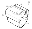
たとえば、図16にその外観を示されるように、血圧計100は、その本体がカフと一体に構成されていても良い。
For example, as shown in FIG. 16, the
[10.変形例(4)]
以上説明した本実施の形態では、圧力センサは、静電容量型のものであったが、本発明の血圧測定装置はこのようなものに限定されない。
[10. Modification (4)]
In the present embodiment described above, the pressure sensor is of the capacitive type, but the blood pressure measurement device of the present invention is not limited to such a type.
たとえば、図17に示されるように、第1圧力センサ131において、可動電極304および固定電極303の代わりに、ピエゾ素子310が設けられても良い。また、第2圧力センサ132において、可動電極404および固定電極403の代わりに、ピエゾ素子410が設けられても良い。
For example, as shown in FIG. 17, in the
本変形例の血圧計の第1圧力センサ131では、空気袋151内の圧力変化がエア管140Aを介してダイヤフラム306に伝えられる。これにより、ダイヤフラム306の伸縮態様が変化し、ピエゾ素子310が変形する。第1圧力センサ131では、ピエゾ素子310の変形に伴って変化する当該ピエゾ素子310の抵抗値の変化を(図示せぬ回路により)検出して、空気袋151内の圧力の変化を検出する。
In the
第2圧力センサ132では、空気袋151内の圧力変化がエア管140Bを介してダイヤフラム406に伝えられる。これにより、ダイヤフラム406の伸縮態様が変化し、ピエゾ素子410が変形する。第2圧力センサ132では、ピエゾ素子410の変形に伴って変化する当該ピエゾ素子410の抵抗値の変化を(図示せぬ回路により)検出して、空気袋151内の圧力の変化を検出する。
In the
空気袋151内の圧力が上昇すると、ダイヤフラム306およびピエゾ素子310は矢印A11の向きに変位し、ダイヤフラム406およびピエゾ素子410は矢印A21の向きに変位する。矢印A11の向きの変位は重力に逆らう向きの変位であるのに対し、矢印A21の向きの変位は重力に沿った向きの変位である。よって、空気袋151内の圧力が一定量上昇した場合でも、ピエゾ素子310とピエゾ素子410に対する自重の影響が異なるため、ピエゾ素子310とピエゾ素子410の変位量は異なると考えられる。
When the pressure in the
本変形例では、上記のような変位量の差異に基づいて、複数の圧力センサの異常の有無が検出される。 In the present modification, the presence / absence of abnormality of the plurality of pressure sensors is detected based on the difference in displacement as described above.
[11.変形例(5)]
本変形例では、図18に示されるように、第1圧力センサ131と第2圧力センサ132が、空気袋151の圧力変化に伴って変位する面(面304Aと面404A)が、変位の向きは同じであるが、その高さが異なるように、配置されている。高さに応じて重力が印加される大きさが異なる。よって、このような配置であっても、第1圧力センサ131と第2圧力センサ132では、同じ空気袋151の圧力変化が生じた場合でも、ダイヤフラム306の変位量とダイヤフラム406の変位量は異なり、また、可動電極304の変位量と可動電極404の変位量とは異なる。
[11. Modification (5)]
In this modification, as shown in FIG. 18, the
本変形例では、このような変位量の差異に基づいて、複数の圧力センサの異常の有無が検出される。 In this modification, the presence / absence of abnormality of the plurality of pressure sensors is detected based on such a difference in displacement.
今回開示された各実施の形態はすべての点で例示であって制限的なものではないと考えられるべきである。本発明の範囲は上記した説明ではなくて特許請求の範囲によって示され、特許請求の範囲と均等の意味および範囲内でのすべての変更が含まれることが意図される。 Each embodiment disclosed this time must be considered as illustrative in all points and not restrictive. The scope of the present invention is defined by the terms of the claims, rather than the description above, and is intended to include any modifications within the scope and meaning equivalent to the terms of the claims.
100 血圧計、100A 本体、110 中央処理部、111 血圧算出部、112 判断部、121 第1発振回路、122 第2発振回路、124 ポンプ駆動回路、125 弁駆動回路、131 第1圧力センサ、132 第2圧力センサ、134 ポンプ、135 弁、140,140A,140B エア管、150 カフ、151 空気袋、160 ハウジング、170 測定部、180 表示部、181,182 メモリ、182A 基準差分値記憶部、183 時計、184 電源回路、185 インターフェース、190 操作部、200,201 基板、301 キャップ、302 ネジ、303,403 固定電極、304,404 可動電極、306,406 ダイヤフラム、307,407 第2ベース、308,408 第1ベース、308A 孔、308B,408B 管部、310,410 ピエゾ素子、500,510 表示画面。
DESCRIPTION OF
Claims (5)
前記カフ内の圧力を検出する複数の圧力センサと、
前記圧力センサの検出出力に基づいて血圧の指標についての値を決定する決定部とを備え、
前記圧力センサは、重力が前記カフ内の圧力の検出に及ぼす影響が互いに異なる状態で設けられており、
複数の前記圧力センサの検出出力が、重力によって及ぼされる影響の違いによって想定される範囲内であるか否かを判断することにより、複数の前記圧力センサの少なくとも一方が異常であるか否かを判断する判断部をさらに備える、血圧測定装置。 A cuff that compresses the measurement site by being wound,
A plurality of pressure sensors for detecting pressure in the cuff;
A determination unit that determines a value for an index of blood pressure based on a detection output of the pressure sensor;
The pressure sensor is provided in a state where the influence of gravity on the detection of the pressure in the cuff is different from each other,
It is determined whether or not at least one of the plurality of pressure sensors is abnormal by determining whether or not the detection outputs of the plurality of pressure sensors are within a range assumed due to a difference in influence exerted by gravity. A blood pressure measurement device further comprising a determination unit for determining.
複数の前記圧力センサは、前記面の圧力変化に対する変位の向きが互いに異なるように設けられている、請求項1に記載の血圧測定装置。 Each of the pressure sensors has a surface that is displaced based on a change in pressure in the cuff,
The blood pressure measurement device according to claim 1, wherein the plurality of pressure sensors are provided such that displacement directions with respect to a pressure change of the surface are different from each other.
複数の前記圧力センサは、前記面の鉛直方向の高さが異なるように設けられた2個の圧力センサを含む、請求項1に記載の血圧測定装置。 Each of the pressure sensors has a surface that is displaced based on a change in pressure in the cuff,
The blood pressure measurement device according to claim 1, wherein the plurality of pressure sensors include two pressure sensors provided so that the heights of the surfaces in the vertical direction are different.
Priority Applications (2)
| Application Number | Priority Date | Filing Date | Title |
|---|---|---|---|
| JP2010292742A JP2012139286A (en) | 2010-12-28 | 2010-12-28 | Blood pressure measuring apparatus |
| US13/338,551 US20120165687A1 (en) | 2010-12-28 | 2011-12-28 | Sphygmomanometer |
Applications Claiming Priority (1)
| Application Number | Priority Date | Filing Date | Title |
|---|---|---|---|
| JP2010292742A JP2012139286A (en) | 2010-12-28 | 2010-12-28 | Blood pressure measuring apparatus |
Publications (1)
| Publication Number | Publication Date |
|---|---|
| JP2012139286A true JP2012139286A (en) | 2012-07-26 |
Family
ID=46317957
Family Applications (1)
| Application Number | Title | Priority Date | Filing Date |
|---|---|---|---|
| JP2010292742A Withdrawn JP2012139286A (en) | 2010-12-28 | 2010-12-28 | Blood pressure measuring apparatus |
Country Status (2)
| Country | Link |
|---|---|
| US (1) | US20120165687A1 (en) |
| JP (1) | JP2012139286A (en) |
Families Citing this family (11)
| Publication number | Priority date | Publication date | Assignee | Title |
|---|---|---|---|---|
| US20130080084A1 (en) * | 2011-09-28 | 2013-03-28 | John P. Miller | Pressure transmitter with diagnostics |
| CN105377125B (en) * | 2014-03-28 | 2018-11-02 | 深圳市大富网络技术有限公司 | A kind of blood pressure detector and relevant apparatus and communication system |
| CN105407795B (en) * | 2014-03-28 | 2018-08-07 | 深圳市大富网络技术有限公司 | Healthy data cloud processing method, mobile terminal and communication system |
| CN106691422B (en) * | 2017-01-19 | 2020-08-04 | 深圳金亿帝医疗设备股份有限公司 | Be applied to sphygmomanometer's valve, integrated air pump and electronic sphygmomanometer |
| CN107174229A (en) * | 2017-05-16 | 2017-09-19 | 深圳金亿帝医疗设备股份有限公司 | Pulse pressure conducting structure, portable blood pressure detection module and Intelligent worn device |
| USD984644S1 (en) * | 2021-03-23 | 2023-04-25 | Shenzhen Aoj Medical Technology Co., Ltd. | Electronic sphygmomanometer |
| USD975282S1 (en) * | 2021-03-23 | 2023-01-10 | Shenzhen Aoj Medical Technology Co., Ltd. | Electronic sphygmomanometer |
| CN115670411A (en) * | 2021-07-30 | 2023-02-03 | 华为技术有限公司 | Blood pressure measuring equipment |
| USD1017041S1 (en) * | 2022-01-05 | 2024-03-05 | Shenzhen Urion Technology Co., Ltd. | Electronic sphygmomanometer |
| USD998153S1 (en) * | 2022-02-25 | 2023-09-05 | Shenzhen Yuanrui Information Technology Co., Ltd | Sphygmomanometer |
| USD995784S1 (en) * | 2022-06-01 | 2023-08-15 | Shenzhen Imdk Medical Technology Co., Ltd | Sphygmomanometer |
Family Cites Families (47)
| Publication number | Priority date | Publication date | Assignee | Title |
|---|---|---|---|---|
| US4458690A (en) * | 1982-05-24 | 1984-07-10 | Novatec, Inc. | Blood pressure monitor |
| JPS62292137A (en) * | 1986-06-11 | 1987-12-18 | 株式会社 シグナル テクノロジ− | Hemomanometer |
| EP0329806B1 (en) * | 1988-02-25 | 1990-10-03 | Hewlett-Packard GmbH | Blood pressure monitor and pneumatic connector therefor |
| US5908027A (en) * | 1994-08-22 | 1999-06-01 | Alaris Medical Systems, Inc. | Tonometry system for monitoring blood pressure |
| US5743856A (en) * | 1995-11-06 | 1998-04-28 | Colin Corporation | Apparatus for measuring pulse-wave propagation velocity |
| US5860932A (en) * | 1996-10-24 | 1999-01-19 | Colin Corporation | Blood pressure monitor |
| JP3495299B2 (en) * | 1999-12-08 | 2004-02-09 | 日本コーリン株式会社 | Pulse wave velocity information measuring device and arterial bifurcation detecting device |
| JP2002291708A (en) * | 2001-03-30 | 2002-10-08 | Omron Corp | Electronic sphygmomanometer |
| JP2003310579A (en) * | 2002-04-24 | 2003-11-05 | Nippon Colin Co Ltd | Organism monitoring apparatus |
| US8303511B2 (en) * | 2002-09-26 | 2012-11-06 | Pacesetter, Inc. | Implantable pressure transducer system optimized for reduced thrombosis effect |
| WO2004041079A1 (en) * | 2002-11-06 | 2004-05-21 | Itamar Medical Ltd. | Detecting medical conditions with noninvasive body probes |
| JP3821099B2 (en) * | 2003-01-24 | 2006-09-13 | オムロンヘルスケア株式会社 | Pulse wave measuring device |
| JP3683257B2 (en) * | 2003-02-28 | 2005-08-17 | コーリンメディカルテクノロジー株式会社 | Blood flow estimation device |
| JP4306381B2 (en) * | 2003-09-17 | 2009-07-29 | オムロンヘルスケア株式会社 | Wrist fixing device for pulse wave measuring device and pulse wave measuring device |
| WO2005058133A2 (en) * | 2003-12-11 | 2005-06-30 | Proteus Biomedical, Inc. | Implantable pressure sensors |
| JP3826938B2 (en) * | 2004-02-18 | 2006-09-27 | オムロンヘルスケア株式会社 | Sphygmomanometer |
| JP3832473B2 (en) * | 2004-02-25 | 2006-10-11 | オムロンヘルスケア株式会社 | Blood pressure measurement device |
| JP3835461B2 (en) * | 2004-04-20 | 2006-10-18 | オムロンヘルスケア株式会社 | Electronic blood pressure monitor |
| JP3815487B2 (en) * | 2004-04-26 | 2006-08-30 | オムロンヘルスケア株式会社 | Wrapping control device for blood pressure measurement band |
| JP4752259B2 (en) * | 2004-12-10 | 2011-08-17 | オムロンヘルスケア株式会社 | Electronic blood pressure monitor and blood pressure measurement system |
| JP4595526B2 (en) * | 2004-12-20 | 2010-12-08 | オムロンヘルスケア株式会社 | Sphygmomanometer cuff and sphygmomanometer |
| US20060200028A1 (en) * | 2005-03-04 | 2006-09-07 | Medwave, Inc. | Sensor-based apparatus and method for portable noninvasive monitoring of blood pressure |
| JP2007044347A (en) * | 2005-08-11 | 2007-02-22 | Omron Healthcare Co Ltd | Sphygmomanometer |
| JP4902153B2 (en) * | 2005-08-12 | 2012-03-21 | オムロンヘルスケア株式会社 | Electronic blood pressure monitor and data processing device |
| JP4687321B2 (en) * | 2005-08-12 | 2011-05-25 | オムロンヘルスケア株式会社 | Electronic blood pressure monitor |
| JP2007044438A (en) * | 2005-08-12 | 2007-02-22 | Omron Healthcare Co Ltd | Electronic sphygmomanometer |
| JP2007044439A (en) * | 2005-08-12 | 2007-02-22 | Omron Healthcare Co Ltd | Electronic sphygmomanometer |
| JP4595739B2 (en) * | 2005-08-15 | 2010-12-08 | オムロンヘルスケア株式会社 | Electronic blood pressure monitor, blood pressure measurement data processing device, program, and recording medium |
| JP2007111119A (en) * | 2005-10-18 | 2007-05-10 | Omron Healthcare Co Ltd | Electronic sphygmomanometer |
| JP2007125079A (en) * | 2005-11-01 | 2007-05-24 | Omron Healthcare Co Ltd | Electronic sphygmomanometer |
| JP2007130069A (en) * | 2005-11-08 | 2007-05-31 | Omron Healthcare Co Ltd | Electronic hemomanometer and data display method of it |
| JP2007135818A (en) * | 2005-11-17 | 2007-06-07 | Omron Healthcare Co Ltd | Electronic sphygmomanometer and method of reporting number of measurements in electronic sphygmomanometer |
| JP4240034B2 (en) * | 2005-11-30 | 2009-03-18 | オムロンヘルスケア株式会社 | Blood pressure measurement device |
| JP4325639B2 (en) * | 2005-12-05 | 2009-09-02 | オムロンヘルスケア株式会社 | Blood pressure measuring device |
| JP4470876B2 (en) * | 2005-12-20 | 2010-06-02 | オムロンヘルスケア株式会社 | Electronic blood pressure monitor |
| JP4659646B2 (en) * | 2006-03-01 | 2011-03-30 | 学校法人自治医科大学 | Blood pressure measurement device |
| US7699786B2 (en) * | 2006-04-05 | 2010-04-20 | Omron Healthcare Co., Ltd. | Electronic blood pressure monitor |
| JP4702216B2 (en) * | 2006-08-03 | 2011-06-15 | オムロンヘルスケア株式会社 | Electronic blood pressure monitor and control method thereof |
| JP4552919B2 (en) * | 2006-10-05 | 2010-09-29 | オムロンヘルスケア株式会社 | Sphygmomanometer cuff and sphygmomanometer |
| US8461997B2 (en) * | 2006-11-20 | 2013-06-11 | St. Jude Medical Systems Ab | Transceiver unit in a measurement system |
| JP2008136655A (en) * | 2006-12-01 | 2008-06-19 | Omron Healthcare Co Ltd | Sphygmometric electrode unit and sphygmometer |
| US7717855B2 (en) * | 2006-12-06 | 2010-05-18 | The Hospital For Sick Children | System for performing remote ischemic preconditioning |
| DE102007048880B4 (en) * | 2007-10-11 | 2009-07-30 | Up Management Gmbh | A sphygmomanometer and method of operating a sphygmomanometer |
| GB0723205D0 (en) * | 2007-11-27 | 2008-01-09 | Ge Healthcare Bio Sciences Ab | Multi-component part pressure transducer assembley |
| JP4978483B2 (en) * | 2008-01-23 | 2012-07-18 | オムロンヘルスケア株式会社 | Blood pressure measurement device and blood pressure measurement data processing method |
| JP5303939B2 (en) * | 2008-01-23 | 2013-10-02 | オムロンヘルスケア株式会社 | Blood pressure monitor measurement accuracy confirmation system |
| US20100010357A1 (en) * | 2008-07-09 | 2010-01-14 | Morris Ostrowiecki | Disposable air bag for a blood pressure measuring device and a method of making the same |
-
2010
- 2010-12-28 JP JP2010292742A patent/JP2012139286A/en not_active Withdrawn
-
2011
- 2011-12-28 US US13/338,551 patent/US20120165687A1/en not_active Abandoned
Also Published As
| Publication number | Publication date |
|---|---|
| US20120165687A1 (en) | 2012-06-28 |
Similar Documents
| Publication | Publication Date | Title |
|---|---|---|
| JP2012139286A (en) | Blood pressure measuring apparatus | |
| RU2316249C2 (en) | Cuff for measuring arterial blood pressure, arterial blood pressure metering device, device for compressing living body and device for measuring data on living body | |
| JP2664982B2 (en) | Blood pressure monitoring device | |
| KR101577342B1 (en) | The Apparatus and Method for measuring blood pressure | |
| TWI376218B (en) | ||
| JP5324569B2 (en) | Thigh compression device | |
| CN102256540A (en) | Electronic apparatus for measuring blood pressure | |
| JP4854014B2 (en) | Vascular viscoelasticity index measuring device | |
| US9307916B2 (en) | Electronic sphygmomanometer | |
| WO2006109519A1 (en) | Blood pressure measuring device and blood pressure measuring method | |
| CN103841883A (en) | Electronic sphygmomanometer | |
| RU2550727C2 (en) | Electronic sphygmomanometer | |
| JP2011239840A (en) | Blood pressure measuring system | |
| JP2009066356A (en) | Bioinformation measuring apparatus | |
| US8998819B2 (en) | Electronic sphygmomanometer | |
| KR102554695B1 (en) | Blood pressure measurement device and method | |
| JP6584297B2 (en) | Pulse wave measuring device and pulse wave measuring method | |
| KR101283798B1 (en) | Apparatus and method for automatic measurement of blood pressure values based on oscillometric method and korotkoff sounds method | |
| CN111033203B (en) | Pressure measuring device and pressure measuring method | |
| JPH05261072A (en) | Pressure pulse wave detector | |
| JP3002598B2 (en) | Pressure pulse wave detector | |
| US20180206731A1 (en) | Pressure sensor and blood pressure measurement device | |
| EP3973857A1 (en) | Estimating central blood pressure | |
| JP2017047093A (en) | Pressure gauge, pressure measurement device, and sphygmomanometer | |
| JP2009198379A (en) | Electronic clinical thermometer |
Legal Events
| Date | Code | Title | Description |
|---|---|---|---|
| A300 | Application deemed to be withdrawn because no request for examination was validly filed |
Free format text: JAPANESE INTERMEDIATE CODE: A300 Effective date: 20140304 |