JP2012138787A - Image processor, image processing method, and program - Google Patents
Image processor, image processing method, and program Download PDFInfo
- Publication number
- JP2012138787A JP2012138787A JP2010290194A JP2010290194A JP2012138787A JP 2012138787 A JP2012138787 A JP 2012138787A JP 2010290194 A JP2010290194 A JP 2010290194A JP 2010290194 A JP2010290194 A JP 2010290194A JP 2012138787 A JP2012138787 A JP 2012138787A
- Authority
- JP
- Japan
- Prior art keywords
- image
- depth information
- unit
- reliability
- output
- Prior art date
- Legal status (The legal status is an assumption and is not a legal conclusion. Google has not performed a legal analysis and makes no representation as to the accuracy of the status listed.)
- Ceased
Links
- 238000003672 processing method Methods 0.000 title claims description 11
- 238000012545 processing Methods 0.000 claims abstract description 266
- 238000006243 chemical reaction Methods 0.000 claims abstract description 241
- 238000000034 method Methods 0.000 claims description 248
- 230000008569 process Effects 0.000 claims description 125
- 238000003384 imaging method Methods 0.000 claims description 26
- 238000004364 calculation method Methods 0.000 claims description 23
- 238000003860 storage Methods 0.000 claims description 6
- 239000000284 extract Substances 0.000 claims description 4
- 239000013589 supplement Substances 0.000 claims 1
- 230000008859 change Effects 0.000 abstract description 2
- 230000006870 function Effects 0.000 description 12
- 238000004458 analytical method Methods 0.000 description 11
- 239000000203 mixture Substances 0.000 description 11
- 238000007781 pre-processing Methods 0.000 description 10
- 238000012805 post-processing Methods 0.000 description 8
- 230000007423 decrease Effects 0.000 description 5
- 238000010586 diagram Methods 0.000 description 5
- 230000000694 effects Effects 0.000 description 4
- 238000012886 linear function Methods 0.000 description 4
- 238000001514 detection method Methods 0.000 description 3
- 238000009877 rendering Methods 0.000 description 3
- 239000003086 colorant Substances 0.000 description 2
- 238000012937 correction Methods 0.000 description 2
- 238000005516 engineering process Methods 0.000 description 2
- 230000009466 transformation Effects 0.000 description 2
- 238000012935 Averaging Methods 0.000 description 1
- 230000002159 abnormal effect Effects 0.000 description 1
- 208000003464 asthenopia Diseases 0.000 description 1
- 238000004891 communication Methods 0.000 description 1
- 238000007796 conventional method Methods 0.000 description 1
- 230000003247 decreasing effect Effects 0.000 description 1
- 230000003111 delayed effect Effects 0.000 description 1
- 230000004069 differentiation Effects 0.000 description 1
- 238000009826 distribution Methods 0.000 description 1
- 238000003708 edge detection Methods 0.000 description 1
- 239000011521 glass Substances 0.000 description 1
- 239000004973 liquid crystal related substance Substances 0.000 description 1
- 238000004519 manufacturing process Methods 0.000 description 1
- 238000002156 mixing Methods 0.000 description 1
- 238000012986 modification Methods 0.000 description 1
- 230000004048 modification Effects 0.000 description 1
- 230000010287 polarization Effects 0.000 description 1
- 230000009467 reduction Effects 0.000 description 1
- 238000006467 substitution reaction Methods 0.000 description 1
Images


Classifications
-
- H—ELECTRICITY
- H04—ELECTRIC COMMUNICATION TECHNIQUE
- H04N—PICTORIAL COMMUNICATION, e.g. TELEVISION
- H04N13/00—Stereoscopic video systems; Multi-view video systems; Details thereof
- H04N13/20—Image signal generators
- H04N13/261—Image signal generators with monoscopic-to-stereoscopic image conversion
-
- H—ELECTRICITY
- H04—ELECTRIC COMMUNICATION TECHNIQUE
- H04N—PICTORIAL COMMUNICATION, e.g. TELEVISION
- H04N13/00—Stereoscopic video systems; Multi-view video systems; Details thereof
- H04N13/10—Processing, recording or transmission of stereoscopic or multi-view image signals
- H04N13/106—Processing image signals
- H04N13/128—Adjusting depth or disparity
Abstract
Description
本発明は、画像処理装置、および画像処理方法、並びにプログラムに関し、特に2次元画像に対する画像変換を実行してステレオ視(立体視)に対応した両眼視差画像を生成する画像処理装置、および画像処理方法、並びにプログラムに関する。 The present invention relates to an image processing device, an image processing method, and a program, and in particular, an image processing device that performs image conversion on a two-dimensional image to generate a binocular parallax image corresponding to stereo vision (stereoscopic vision), and an image The present invention relates to a processing method and a program.
2次元画像をステレオ視(立体視)に対応した両眼視差画像に変換する装置および方法について従来から様々な提案がなされている。2次元画像に基づいて生成された両眼視差画像は、左眼で観察する左眼用画像と右眼で観察する右眼用画像のペアによって構成される。これらの左眼用画像と右眼用画像のペアによって構成される両眼視差画像を、左眼用画像と右眼用画像をそれぞれ分離して観察者の左眼と右眼に提示することを可能とした表示装置に表示することで、観察者は画像を立体画像として知覚することができる。 Conventionally, various proposals have been made on an apparatus and a method for converting a two-dimensional image into a binocular parallax image corresponding to stereo vision (stereoscopic vision). The binocular parallax image generated based on the two-dimensional image is composed of a pair of a left-eye image observed with the left eye and a right-eye image observed with the right eye. A binocular parallax image composed of a pair of these left-eye image and right-eye image is presented to the left and right eyes of the observer by separating the left-eye image and the right-eye image, respectively. By displaying on the enabled display device, the observer can perceive the image as a stereoscopic image.
このような画像の生成や表示処理に関して開示した従来技術は、その手法に基づいて例えば以下のようなカテゴリに分類できる。
(A)時間軸方向の複数の2次元画像から3次元画像を生成する手法
(a1)時間軸方向に2枚以上の画像を撮像し、その内の2画像で左右ペアの代用とする手法
(a2)時間軸方向に2枚以上の画像を撮像し、画像内の物体の動きベクトルを求め、手前の物体ほど見かけの動きが速く、動いた距離が大きい事などを利用し前後関係を推定したりして、背景と主要被写体の分離等を行いレンダリングする手法
The prior art disclosed regarding such image generation and display processing can be classified into the following categories based on the method.
(A) Method of generating a three-dimensional image from a plurality of two-dimensional images in the time axis direction (a1) Method of taking two or more images in the time axis direction and substituting the left and right pairs with two of the images a2) Take two or more images in the time axis direction, determine the motion vector of the object in the image, and estimate the context using the fact that the apparent motion is faster and the distance moved is greater for the object in the foreground. To render the background and main subject, etc.
(B)単一の2次元画像から3次元画像を生成する手法
(b1)1枚の画像を左右画像生成のため、所定量だけ水平方向にずらし、画像が浮き上がったように知覚させる手法
(b2)1枚の画像のみから、エッジやカラー、輝度、ヒストグラム等で構図(シーン)解析を行い、奥行きを推定しレンダリングする手法
(b3)1枚の画像のみから、周波数成分やエッジ成分等を用いて左右視差成分を抽出しレンダリングする手法
(B) A method for generating a three-dimensional image from a single two-dimensional image (b1) A method for shifting a single image horizontally by a predetermined amount in order to generate left and right images and perceiving the image as if it floated (b2 ) A method that performs composition (scene) analysis from only one image by edge, color, brightness, histogram, etc., and estimates and renders depth (b3) Using frequency components, edge components, etc. from only one image To extract the left and right parallax components and render
(C)2次元画像と奥行情報から3次元画像を生成する手法
(c1)1枚の画像の他に、測拒センサを用いたり、フォーカスの異なる複数の画像から演算したりする方法で奥行情報を取得し、その奥行情報で、2次元画像を主体的に利用して空間幾何学的にレンダリングする手法
(c2)1枚の画像の他に、測拒センサを用いたり、フォーカスの異なる複数の画像から演算したりする方法で奥行情報を取得し、前述の単一の2次元画像から3次元画像を生成する方法を主体として、あくまでも補助的に奥行情報を用いて3次元画像を生成する手法
(C) Method for generating a three-dimensional image from a two-dimensional image and depth information (c1) Depth information by using a refusal sensor or calculating from a plurality of images with different focus in addition to a single image (C2) In addition to a single image, using a refusal sensor or a plurality of different focus points Depth information is acquired by a method of calculating from an image, and a method of generating a three-dimensional image using depth information as a supplementary method mainly using the above-described method of generating a three-dimensional image from a single two-dimensional image.
2次元画像から3次元画像を生成する手法として、従来技術として提案されている手法を文明すると例えば上記のように分類できる。 As a technique for generating a three-dimensional image from a two-dimensional image, a technique proposed as a conventional technique can be classified as described above, for example.
(a1)時間軸方向に2枚以上の画像を撮像し、その内の2画像で左右ペアの代用とする手法
この手法については、例えば、特許文献1(特開平9−107562号公報)に記載がある。この特許文献1は、水平方向に動きがある動画像に対する画像処理構成を開示している。具体的には左眼用画像または右眼用画像の一方に原画像を出力し、他方にはフィールド単位で遅延させた画像を出力する構成である。このような画像出力制御により、水平に移動する物体を背景よりも手前に知覚させるものである。
(A1) A method of taking two or more images in the time axis direction and substituting the left and right pairs with two of the images. This method is described in, for example, Japanese Patent Application Laid-Open No. 9-107562. There is. This Patent Document 1 discloses an image processing configuration for a moving image that moves in the horizontal direction. Specifically, the original image is output to one of the left-eye image and the right-eye image, and the image delayed by the field unit is output to the other. By such image output control, a horizontally moving object is perceived in front of the background.
(a2)時間軸方向に2枚以上の画像を撮像し、画像内の物体の動きベクトルを求め、手前の物体ほど見かけの動きが速く、動いた距離が大きい事などを利用し前後関係を推定したりして、背景と主要被写体の分離等を行いレンダリングする手法
この手法については、例えば、特許文献2(特開2000−261828号公報)、特許文献3(特開平9−161074号公報)、特許文献4(特開平8−331607号公報)に記載がある。これらの特許文献には、時間軸での複数の画像からブロックマッチング等の手法を用いて奥行きを推定し、左右視差画像を生成する方法を提案している。
(A2) Take two or more images in the time axis direction, determine the motion vector of the object in the image, and estimate the context using the fact that the front object is faster and the distance moved is larger For example, Patent Document 2 (Japanese Patent Laid-Open No. 2000-261828), Patent Document 3 (Japanese Patent Laid-Open No. 9-161074), There is description in Patent Document 4 (Japanese Patent Laid-Open No. 8-331607). In these patent documents, a method of estimating the depth from a plurality of images on the time axis using a technique such as block matching and generating a left-right parallax image is proposed.
(b1)1枚の画像を左右画像生成のため、所定量だけ水平方向にずらし、画像が浮き上がったように知覚させる手法
この手法については、例えば特許文献5(特開平8−30806号公報)に記載がある。この特許文献5は、静止画像や動きの少ない画像に対して、左眼用画像と右眼用画像を所定量だけ水平方向にずらすことにより、画像が浮き上がったように知覚させる装置を提案している。
(B1) A method of shifting one image horizontally by a predetermined amount in order to generate left and right images and perceiving the image as being lifted. For this method, for example, Patent Document 5 (Japanese Patent Laid-Open No. 8-30806) There is a description. This Patent Document 5 proposes an apparatus that perceives an image as if it floated by shifting a left-eye image and a right-eye image in a horizontal direction by a predetermined amount with respect to a still image or an image with little motion. Yes.
また、上記項目(b1)と、
(b2)1枚の画像のみから、エッジやカラー、輝度、ヒストグラム等で構図(シーン)解析を行い、奥行きを推定しレンダリングする手法
これらの手法を開示した従来技術として特許文献6(特開平10−51812号公報)がある。この特許文献6は、画像を複数の視差算出領域に分割し、各領域に おいて画像の特徴量から擬似的な奥行きを算出し、奥行きに基づいて左眼用画像と右眼用 画像を反対方向に水平シフトする方法を提案している。
In addition, the item (b1),
(B2) A method of performing composition (scene) analysis from only one image with edges, colors, luminance, histogram, etc., and estimating and rendering the depth As a prior art disclosing these methods, Patent Document 6 -51812). This patent document 6 divides an image into a plurality of parallax calculation regions, calculates a pseudo depth from the image feature amount in each region, and reverses the left-eye image and the right-eye image based on the depth. A method of horizontal shifting in the direction is proposed.
また、上記項目(b2)の手法については、特許文献7(特開2005−151534号公報)にも記載がある。特許文献7は、画像の構造を比較的単純な有限の構造(構図)モデルに当てはめる構成を提案し、不自然な奥行きの発生を抑制する構成を開示している。 The method of item (b2) is also described in Patent Document 7 (Japanese Patent Laid-Open No. 2005-151534). Patent Document 7 proposes a configuration in which the structure of an image is applied to a relatively simple finite structure (composition) model, and discloses a configuration that suppresses the occurrence of an unnatural depth.
さらに、(b3)1枚の画像のみから、周波数成分やエッジ成分等を用いて左右視差成分を抽出しレンダリングする手法については、特許文献8(特開2010−63083号公報)に開示されている。特許文献8は、微分信号を原画像に加算、もしくは減算することにより左右視差画像を生成する方法を提案している。 Further, (b3) a technique for extracting and rendering a left-right parallax component from only one image using a frequency component, an edge component, or the like is disclosed in Patent Document 8 (Japanese Patent Laid-Open No. 2010-63083). . Patent Document 8 proposes a method of generating a left-right parallax image by adding or subtracting a differential signal to an original image.
また、(c1)1枚の画像の他に、測拒センサを用いたり、フォーカスの異なる複数の画像から演算したりする方法で奥行情報を取得し、その奥行情報で、2次元画像を主体的に利用して空間幾何学的にレンダリングする手法については特許文献9(特開2009−296272号公報)に記載がある。特許文献9は測拒センサを用いて奥行情報を取得し、3次元画像データを取得する方法を提案している。 (C1) In addition to a single image, depth information is acquired by using a refusal sensor or by calculating from a plurality of images with different focus. A method of rendering spatially using the above is described in Patent Document 9 (Japanese Patent Laid-Open No. 2009-296272). Patent Document 9 proposes a method of acquiring depth information using a refusal sensor and acquiring three-dimensional image data.
上述したように、2次元画像から3次元画像を生成する手法として様々な手法が提案されている。しかし、これまでに提案されている手法には例えば以下の問題点がある。 As described above, various techniques have been proposed as a technique for generating a three-dimensional image from a two-dimensional image. However, the methods proposed so far have the following problems, for example.
上記の手法(a1)は、静止画や動きの少ない画像に対しては、画面全体をずらすのみであり、画像中の物体の前後関係を表現することは出来ない。
手法(a2)は、静止画や動きの少ない画像に対しては、動きベクトルが求められず、画像中の物体の前後関係を正しく推定できず、正しい視差を付けることができない。
The above method (a1) only shifts the entire screen for a still image or an image with little motion, and cannot express the context of objects in the image.
With the method (a2), a motion vector cannot be obtained for a still image or an image with little motion, the front-rear relationship of objects in the image cannot be estimated correctly, and correct parallax cannot be given.
手法(b1)は、静止画や動きの少ない画像に対しては、画面全体をずらすのみであり、画像中の物体の前後関係を表現することは出来ない。
手法(b2)は、画像の特徴量から擬似的な奥行きを推定するが、推定は画面前方にある物体の先鋭度が高い、輝度が高い、彩度が高いなどの仮定に基づいており、必ずしも正しい推定が行われるとは限らない。また、1枚の画像から詳細な奥行きを検出することは難しく、構図でない部分、たとえば、樹木の枝や電線、髪の毛のような微細な構造に対する奥行きの推定を行うことは容易ではない。このため、奥行き推定を誤った部分に対しては誤った視差が与えられてしまう。また、有限の構造(構図)では全ての構造(構図)をカバーする事はできないので本質的な解決にはならない。
手法(b3)は、もともと2次元画像内の周波数成分(特に高周波成分)を用いているだけで、実際の奥行とは相関が低い事も多く、画像内に不自然な奥行感を発生させてしまう。
The method (b1) only shifts the entire screen for a still image or an image with little motion, and cannot express the context of objects in the image.
The method (b2) estimates the pseudo depth from the feature amount of the image, but the estimation is based on the assumption that the sharpness of the object in front of the screen is high, the brightness is high, the saturation is high, etc. A correct estimate is not always made. In addition, it is difficult to detect the detailed depth from one image, and it is not easy to estimate the depth for a fine structure such as a branch of a tree, an electric wire, or a hair. For this reason, an incorrect parallax is given to a portion where the depth estimation is incorrect. In addition, since a finite structure (composition) cannot cover all structures (composition), it is not an essential solution.
Method (b3) originally uses frequency components (especially high-frequency components) in a two-dimensional image, and often has a low correlation with the actual depth, causing an unnatural depth in the image. End up.
手法(c1)は、現在の技術では画像内の全ての画素毎の正確な奥行(距離)の測定はできず(精度が低く)、その奥行情報を用いた方法では不自然な視差を発生させてしまう。
手法(c2)は、奥行情報を補助的に用いるだけで、手法(b1)〜(b3)と本質的に変わらない。
The method (c1) cannot accurately measure the depth (distance) for every pixel in the image with the current technology (accuracy is low), and the method using the depth information generates unnatural parallax. End up.
The technique (c2) is essentially the same as the techniques (b1) to (b3) only using the depth information as an auxiliary.
簡単にまとめると奥行情報を用いない変換方法では、奥行の推定しかできないので、多くのケースで誤りが生じ、高品質な左右視差画像を生成することができないという問題が発生する。 To summarize, since the conversion method that does not use depth information can only estimate depth, an error occurs in many cases, and a problem arises that a high-quality left-right parallax image cannot be generated.
また、現在の技術水準では、測拒センサ等を用いても1画素単位の分解能で正確な奥行情報を取得することは非常に困難であり、その正確でない奥行情報を主体的に用いる幾何学的2D−3D変換方法では高品質な左右視差画像を生成することができない。 Also, with the current technical level, it is very difficult to obtain accurate depth information with a resolution of one pixel even if a refractometer sensor or the like is used, and geometric information that mainly uses the inaccurate depth information. In the 2D-3D conversion method, a high-quality left-right parallax image cannot be generated.
以上のように、2次元画像のみから左右視差画像を生成する場合も2次元画像から奥行情報を推定して左右視差画像を生成する場合も、測定した奥行情報と2次元画像から幾何学的に左右視差画像を生成する場合も、何らかの技術的課題があり、奥行情報に大きく画像品質が左右され、現在の技術では高品位な立体感を持つ左右視差画像を生成することはできない。 As described above, both when generating a left-right parallax image from only a two-dimensional image and when generating a left-right parallax image by estimating depth information from a two-dimensional image, geometrically from the measured depth information and the two-dimensional image. There is also some technical problem when generating left and right parallax images, and the image quality is greatly affected by depth information, and the current technology cannot generate a left and right parallax image with a high-quality stereoscopic effect.
すなわち、誤りを持った奥行情報を用いた左右視差画像生成では、生成する画像の中に、間違った視差量が付加され、あり得ない視差が付いてしまったり、現実と遠近感が狂っている(誤っている)部分が生じ、立体視した時に不自然さや違和感となる。低品位の左右視差画像を用いた立体画像は不自然さを感じて快適に視聴できないばかりか、眼精疲労を生じさせてしまうことが知られている。 In other words, in left / right parallax image generation using depth information with errors, an incorrect amount of parallax is added to the generated image, and impossible parallax is added, or reality and perspective are crazy. A (wrong) part is generated, and it becomes unnatural and uncomfortable when stereoscopically viewed. It is known that stereoscopic images using low-quality left and right parallax images not only feel unnatural and can be comfortably viewed, but also cause eye strain.
本発明は、例えばこれらの問題を解決し、測定または推定された奥行き情報の誤りに起因する誤った立体感の発生を抑制した高品質な左右視差画像の生成、提示を実現する画像処理装置、および画像処理方法、並びにプログラムを提供することにある。 The present invention, for example, an image processing apparatus that solves these problems and realizes generation and presentation of a high-quality left-right parallax image that suppresses the occurrence of an erroneous stereoscopic effect due to an error in measured or estimated depth information, And an image processing method and a program.
本発明の第1の側面は、
2次元画像信号を入力する画像入力部と、
前記2次元画像信号を構成する画像領域単位の奥行情報を入力または生成する奥行情報出力部と、
前記奥行情報出力部の出力する奥行情報の信頼度を入力または生成する奥行情報信頼度出力部と、
前記画像入力部から出力される画像信号と、前記奥行情報出力部の出力する奥行情報と、前記奥行情報信頼度出力部の出力する奥行情報信頼度を入力して、両眼立体視を実現するための左眼用画像と右眼用画像を生成して出力する画像変換部と、
前記画像変換部から出力される左眼用画像と右眼用画像を出力する画像出力部を具備し、
前記画像変換部は、入力画像信号に対する画像変換処理により左眼用画像または右眼用画像の少なくともいずれかの画像生成を行う構成であり、
前記画像変換に際して、前記奥行情報と前記奥行情報信頼度を変換制御データとして適用した変換処理を実行する画像処理装置にある。
The first aspect of the present invention is:
An image input unit for inputting a two-dimensional image signal;
A depth information output unit for inputting or generating depth information in units of image areas constituting the two-dimensional image signal;
A depth information reliability output unit for inputting or generating the reliability of the depth information output by the depth information output unit;
Binocular stereopsis is realized by inputting an image signal output from the image input unit, depth information output from the depth information output unit, and depth information reliability output from the depth information reliability output unit. An image conversion unit that generates and outputs an image for the left eye and an image for the right eye,
An image output unit that outputs a left-eye image and a right-eye image output from the image conversion unit;
The image conversion unit is configured to perform image generation of at least one of a left-eye image and a right-eye image by image conversion processing on an input image signal,
In the image conversion, the image processing apparatus executes conversion processing in which the depth information and the depth information reliability are applied as conversion control data.
さらに、本発明の画像処理装置の一実施態様において、前記画像変換部は、前記奥行情報信頼度が予め既定した閾値以上であり信頼度が高いと判定した場合は、前記奥行情報を主体的に適用した画像変換処理により、入力2次元画像から左眼用画像または右眼用画像を生成する処理を実行する。 Furthermore, in an embodiment of the image processing device of the present invention, the image conversion unit mainly uses the depth information when the depth information reliability is equal to or higher than a predetermined threshold and the reliability is high. By the applied image conversion processing, processing for generating a left-eye image or a right-eye image from the input two-dimensional image is executed.
さらに、本発明の画像処理装置の一実施態様において、前記画像変換部は、前記奥行情報信頼度が予め既定した閾値未満であり信頼度が低いと判定した場合は、前記奥行情報を利用しない画像変換処理により、入力2次元画像から左眼用画像または右眼用画像を生成する処理を実行する。 Furthermore, in an embodiment of the image processing device of the present invention, the image conversion unit, when it is determined that the depth information reliability is less than a predetermined threshold and the reliability is low, the image does not use the depth information. By the conversion process, a process of generating a left-eye image or a right-eye image from the input two-dimensional image is executed.
さらに、本発明の画像処理装置の一実施態様において、前記画像変換部は、入力画像信号に対する輝度微分信号を特徴量として設定し、入力画像信号に対して前記特徴量を加算した信号と減算した信号を生成し、これらの2つの信号の組を左眼用画像と右眼用画像の組として生成する処理を行う。 Furthermore, in one embodiment of the image processing apparatus of the present invention, the image conversion unit sets a luminance differential signal for the input image signal as a feature amount, and subtracts the signal obtained by adding the feature amount to the input image signal. A signal is generated, and a process of generating a set of these two signals as a set of a left-eye image and a right-eye image is performed.
さらに、本発明の画像処理装置の一実施態様において、前記画像変換部は、前記奥行情報信頼度が予め既定した第1閾値未満であり第2閾値以上であり、信頼度が中程度であると判定した場合は、前記奥行情報を補助的に利用した幾何学的でない画像変換処理により、入力2次元画像から左眼用画像または右眼用画像を生成する処理を実行する。 Furthermore, in one embodiment of the image processing apparatus of the present invention, the image conversion unit is such that the depth information reliability is less than a predetermined first threshold, is greater than or equal to a second threshold, and the reliability is medium. When the determination is made, processing for generating a left-eye image or a right-eye image from the input two-dimensional image is executed by non-geometric image conversion processing using the depth information as an auxiliary.
さらに、本発明の画像処理装置の一実施態様において、前記画像変換部は、入力画像信号の空間的な特徴量を抽出し、抽出特徴量を適用した視差強調成分を算出する視差強調成分算出部と、前記奥行情報と前記奥行情報信頼度に基づく前記視差強調成分の調整を実行する成分量制御部と、前記成分量制御部の出力である成分量の調整された視差強調成分を適用した入力画像に対する画像変換処理により、入力2次元画像から左眼用画像または右眼用画像を生成する処理を実行する視差画像生成部を有する。 Furthermore, in an embodiment of the image processing device of the present invention, the image conversion unit extracts a spatial feature amount of the input image signal and calculates a parallax enhancement component to which the extracted feature amount is applied. A component amount control unit that performs adjustment of the parallax enhancement component based on the depth information and the depth information reliability, and an input that applies a parallax enhancement component with an adjusted component amount that is an output of the component amount control unit It has a parallax image generation unit that executes processing for generating a left-eye image or a right-eye image from an input two-dimensional image by image conversion processing on the image.
さらに、本発明の画像処理装置の一実施態様において、前記画像変換部は、前記奥行情報信頼度に基づく前記奥行情報の重み付けを実行して重み付け設定奥行情報を生成する奥行制御部と、前記奥行制御部の出力である重み設定奥行情報を適用した入力画像に対する画像変換処理により、入力2次元画像から左眼用画像または右眼用画像を生成する処理を実行する視差画像生成部を有する。 Furthermore, in one embodiment of the image processing apparatus of the present invention, the image conversion unit performs weighting of the depth information based on the depth information reliability to generate weight setting depth information, and the depth It has a parallax image generation unit that executes processing for generating an image for the left eye or an image for the right eye from the input two-dimensional image by image conversion processing on the input image to which the weight setting depth information that is the output of the control unit is applied.
さらに、本発明の画像処理装置の一実施態様において、前記画像処理装置は、さらに、前記画像変換部の生成した変換画像を表示する表示部を有する。 Furthermore, in an embodiment of the image processing apparatus of the present invention, the image processing apparatus further includes a display unit that displays the converted image generated by the image conversion unit.
さらに、本発明の画像処理装置の一実施態様において、前記画像処理装置は、さらに、撮像部を有し、前記画像変換部は前記撮像部の撮像画像を入力して処理を実行する。 Furthermore, in an embodiment of the image processing apparatus of the present invention, the image processing apparatus further includes an imaging unit, and the image conversion unit inputs a captured image of the imaging unit and executes processing.
さらに、本発明の画像処理装置の一実施態様において、前記画像処理装置は、さらに、前記画像変換部の生成した変換画像を記録する記憶部を有する。 Furthermore, in an embodiment of the image processing apparatus of the present invention, the image processing apparatus further includes a storage unit that records the converted image generated by the image conversion unit.
さらに、本発明の第2の側面は、
画像処理装置において画像変換処理を実行する画像処理方法であり、
画像入力部が、2次元画像信号を入力する画像入力ステップと、
奥行情報出力部が、前記2次元画像信号を構成する画像領域単位の奥行情報を入力または生成する奥行情報出力ステップと、
奥行情報信頼度出力部が、前記奥行情報出力部の出力する奥行情報の信頼度を入力または生成する奥行情報信頼度出力ステップと、
画像変換部が、前記画像入力部から出力される画像信号と、前記奥行情報出力部の出力する奥行情報と、前記奥行情報信頼度出力部の出力する奥行情報信頼度を入力して、両眼立体視を実現するための左眼用画像と右眼用画像を生成して出力する画像変換ステップと、
画像出力部が、前記画像変換部から出力される左眼用画像と右眼用画像を出力する画像出力ステップを実行し、
前記画像変換ステップは、入力画像信号に対する画像変換処理により左眼用画像または右眼用画像の少なくともいずれかの画像生成を行い、前記画像変換に際して、前記奥行情報と前記奥行情報信頼度を変換制御データとして適用した変換処理を実行する画像処理方法にある。
Furthermore, the second aspect of the present invention provides
An image processing method for executing image conversion processing in an image processing apparatus,
An image input step in which the image input unit inputs a two-dimensional image signal;
A depth information output unit that inputs or generates depth information in units of image areas constituting the two-dimensional image signal; and
A depth information reliability output unit that inputs or generates the reliability of the depth information output by the depth information output unit; and
The image conversion unit inputs the image signal output from the image input unit, the depth information output from the depth information output unit, and the depth information reliability output from the depth information reliability output unit. An image conversion step for generating and outputting a left-eye image and a right-eye image for realizing stereoscopic vision;
The image output unit executes an image output step of outputting the left-eye image and the right-eye image output from the image conversion unit,
In the image conversion step, at least one of a left-eye image and a right-eye image is generated by image conversion processing on an input image signal, and conversion control of the depth information and the depth information reliability is performed at the time of the image conversion. The image processing method executes a conversion process applied as data.
さらに、本発明の第3の側面は、
画像処理装置において画像変換処理を実行させるプログラムであり、
画像入力部に、2次元画像信号を入力させる画像入力ステップと、
奥行情報出力部に、前記2次元画像信号を構成する画像領域単位の奥行情報を入力または生成させる奥行情報出力ステップと、
奥行情報信頼度出力部に、前記奥行情報出力部の出力する奥行情報の信頼度を入力または生成させる奥行情報信頼度出力ステップと、
画像変換部に、前記画像入力部から出力される画像信号と、前記奥行情報出力部の出力する奥行情報と、前記奥行情報信頼度出力部の出力する奥行情報信頼度を入力して、両眼立体視を実現するための左眼用画像と右眼用画像を生成して出力させる画像変換ステップと、
画像出力部に、前記画像変換部から出力される左眼用画像と右眼用画像を出力させる画像出力ステップを実行させ、
前記画像変換ステップにおいては、入力画像信号に対する画像変換処理により左眼用画像または右眼用画像の少なくともいずれかの画像生成を行わせ、前記画像変換に際して、前記奥行情報と前記奥行情報信頼度を変換制御データとして適用した変換処理を実行させるプログラムにある。
Furthermore, the third aspect of the present invention provides
A program for executing an image conversion process in an image processing apparatus;
An image input step for causing the image input unit to input a two-dimensional image signal;
A depth information output step for causing the depth information output unit to input or generate depth information in units of image areas constituting the two-dimensional image signal;
A depth information reliability output step for inputting or generating the reliability of the depth information output by the depth information output unit to the depth information reliability output unit;
The image signal output from the image input unit, the depth information output from the depth information output unit, and the depth information reliability output from the depth information reliability output unit are input to the image conversion unit. An image conversion step of generating and outputting a left-eye image and a right-eye image for realizing stereoscopic vision;
Causing the image output unit to execute an image output step of outputting the left-eye image and the right-eye image output from the image conversion unit;
In the image conversion step, at least one of a left-eye image and a right-eye image is generated by image conversion processing on an input image signal, and the depth information and the depth information reliability are determined in the image conversion. It is in a program for executing a conversion process applied as conversion control data.
なお、本発明のプログラムは、例えば、様々なプログラム・コードを実行可能な汎用システムに対して、コンピュータ可読な形式で提供する記憶媒体、通信媒体によって提供可能なプログラムである。このようなプログラムをコンピュータ可読な形式で提供することにより、コンピュータ・システム上でプログラムに応じた処理が実現される。 The program of the present invention is, for example, a program that can be provided by a storage medium or a communication medium provided in a computer-readable format to a general-purpose system capable of executing various program codes. By providing such a program in a computer-readable format, processing corresponding to the program is realized on the computer system.
本発明のさらに他の目的、特徴や利点は、後述する本発明の実施例や添付する図面に基づくより詳細な説明によって明らかになるであろう。なお、本明細書においてシステムとは、複数の装置の論理的集合構成であり、各構成の装置が同一筐体内にあるものには限らない。 Other objects, features, and advantages of the present invention will become apparent from a more detailed description based on embodiments of the present invention described later and the accompanying drawings. In this specification, the system is a logical set configuration of a plurality of devices, and is not limited to one in which the devices of each configuration are in the same casing.
本発明の一実施例構成によれば、奥行情報の信頼度に応じた最適な信号処理により立体視可能な画像信号を生成する構成が実現される。具体的には、2次元画像に基づいて3次元画像表示に適用する左眼用画像や右眼用画像を生成する構成において、画像信号の領域単位の奥行情報や奥行信頼度情報を入力または生成し、これらの情報に基づいて画像変換の制御を実行する。2次元画像信号を構成する画像領域単位の奥行情報と奥行情報の信頼度を入力または生成し、例えばこれらの情報に基づいて、2D画像を3D画像に変換する変換処理態様を変更する。あるいは視差強調信号の適用レベルの制御等を実行する。これらの処理により2次元画像の奥行情報や奥行信頼度に応じた最適な画像変換が可能となる。 According to the configuration of one embodiment of the present invention, a configuration for generating a stereoscopically viewable image signal by optimal signal processing according to the reliability of depth information is realized. Specifically, in a configuration for generating a left-eye image or a right-eye image to be applied to a three-dimensional image display based on a two-dimensional image, input or generation of depth information or depth reliability information for each region of an image signal Then, image conversion control is executed based on these pieces of information. The depth information of the image area unit constituting the two-dimensional image signal and the reliability of the depth information are input or generated, and the conversion processing mode for converting a 2D image into a 3D image is changed based on such information, for example. Alternatively, control of the application level of the parallax enhancement signal is executed. These processes enable optimal image conversion according to the depth information and depth reliability of the two-dimensional image.
以下、図面を参照しながら本発明の画像処理装置、および画像処理方法、並びにプログラムの詳細について説明する。説明は以下の項目に従って行う。
1.画像処理装置の構成例について
2.奥行情報出力部の処理について
3.奥行情報信頼度出力部の処理について
4.画像変換部の構成と処理について
5.成分量制御部の処理について
6.奥行制御部の処理について
7.視差画像生成部の処理について
8.幾何学的視差画像生成部の処理について
9.画像表示装置に関連した処理について
10.画像変換部の処理シーケンスについて
11.画像変換部の処理シーケンスについて(動画)
12.その他の実施例について
The details of the image processing apparatus, image processing method, and program of the present invention will be described below with reference to the drawings. The explanation will be made according to the following items.
1. 1. Configuration example of image processing apparatus 2. Processing of depth information output unit 3. Processing of depth information reliability output unit 4. Configuration and processing of image conversion unit 5. Processing of component amount control unit 6. Processing of depth control unit 7. Processing of the parallax image generation unit 8. Processing of geometric parallax image generation unit Regarding processing related to the image display device 10. 10. Processing sequence of image conversion unit Processing sequence of image converter (video)
12 About other examples
[1.画像処理装置の構成例について]
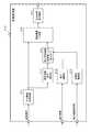
図1および図2はそれぞれ本発明の画像処理装置の一実施例を示す図である。
図1および図2に示すように、本発明の画像処理装置100の前段に、画像処理装置100の処理対象となる画像を入力する入力装置としてディジタルカメラ等の撮像装置51を示し、後段に、画像処理装置100における処理画像を出力する出力装置として3Dテレビ等の表示装置52を記載している。
[1. Configuration example of image processing apparatus]
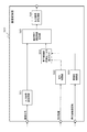
1 and 2 are diagrams showing an embodiment of the image processing apparatus of the present invention.
As shown in FIGS. 1 and 2, an
これら画像の入力装置、出力装置は、撮像装置、表示装置のみに限らず、光磁気メモリや固体メモリ等の記録装置等、さまざまな装置が設定可能である。すなわち、画像処理装置100の前後に構成される装置は特定されるものでなく、必要な情報の入出力が可能な構成であればよい。
また、画像処理装置100自身が撮像装置と一体となった構成としてもよいし、3Dテレビ等の表示装置と一体となった構成としてもよい。
The image input device and the output device are not limited to the imaging device and the display device, and various devices such as a recording device such as a magneto-optical memory or a solid-state memory can be set. That is, the devices configured before and after the
Further, the
図1および図2に示す画像処理装置の構成要素は同じであり、接続構成のみが異なっている。まず、図1を参照して画像処理装置100の構成と処理について説明する。
図1に示す画像処理装置100は、画像入力部101において、各種の撮像装置から出力される2次元画像(2D画像)としての静止画像データや、動画像データを受け取り、画像処理装置100内のデータ処理部で処理可能な内部データ形式に変換する。ここで、内部データ形式とは、ベースバンドの動画像データであり、赤(R)、緑(G)、青(B)の三原色のデータ、または、輝度(Y)、色差(Cb,Cr)のデータ等である。内部データ形式は、後段の画像変換部104で処理可能なデータ形式であればどのような形式でも構わない。
The components of the image processing apparatus shown in FIGS. 1 and 2 are the same, and only the connection configuration is different. First, the configuration and processing of the
An
奥行情報出力部102は、画像入力部101から入力する画像信号に対応した奥行情報を外部から入力、または内部で生成して画像変換部104に出力する。奥行情報出力部102が入力あるいは生成する奥行情報は、入力画像信号と相対的な位置関係が対応し、各画素がどの程度の奥行きを有しているかを決めることが可能な情報であればよい。詳細は後述する。
The depth
奥行情報信頼度出力部103は、奥行情報出力部102が出力する奥行情報に対応した奥行情報信頼度を外部から入力、または内部で生成して画像変換部104に出力する。奥行情報信頼度情報103は、奥行情報と相対的な位置関係が対応し、各画素の奥行情報がどの程度の信頼度を有しているかを判断することが可能な情報であればよい。詳細は後述する。
The depth information
画像変換部104は、画像入力部101から入力する2次元画像(2D画像)、奥行情報出力部102から入力する奥行情報、奥行情報信頼度出力部103から入力する信頼度情報を適用して、入力画像である2次元画像(2D画像)を3次元画像表示に適用する3次元画像(3D画像)に変換する処理を行う。なお、この処理を本明細書では2D−3D変換処理と呼ぶ。画像変換部104は、入力画像である2次元画像(2D画像)の画像変換を行い、左眼用画像と右眼用画像すなわち両眼視差画像を生成する処理を行う。詳しくは後述する。
The
画像変換部104から出力された画像データは画像出力部105で出力に適したフォーマットに変換され出力される。処理の一例としては解像度変換やJPEGやMPEG等のコーデック変換である。
The image data output from the
[2.奥行情報出力部の処理について]
次に、奥行情報出力部102の処理について詳細に説明する。前述の通り奥行情報出力部102は、外部から奥行情報を入力して出力するか、あるいは内部で生成して出力する処理を行う。
[2. Depth information output processing]
Next, the processing of the depth
奥行情報出力部102が入力あるいは生成する奥行情報は、入力画像信号と相対的な位置関係が対応し、各画素がどの程度の奥行き(例えばカメラからの距離)を有しているかを決めることが可能な情報であればよい。奥行情報は、例えば、撮像した位置から無限遠までを画素毎に8bit(0から127)で表した値である。ただしデータ形式は1例であり特定するものでない。
The depth information input or generated by the depth
入力画像の画素数と奥行情報の画素数は、理想的には画素毎の奥行情報を持つ1対1のデータ設定とすることが望ましい。ただし1対1の関係になくても構わず、複数画素からなるブロック対応の奥行情報としてもよい。また、入力画像サイズを縮小したサイズ、すなわち、あるエリアに対し1つの奥行情報を設定した構成としてもよい。縮小画像の各画素対応の奥行情報に基づいて適切な補間処理を適用することで、元画像としての拡大画像の各画素単位の奥行情報を算出できる。 Ideally, the number of pixels in the input image and the number of pixels in the depth information should be set to one-to-one data having depth information for each pixel. However, the relationship may not be a one-to-one relationship, and may be depth information corresponding to a block composed of a plurality of pixels. Further, the input image size may be reduced, that is, one depth information may be set for a certain area. By applying an appropriate interpolation process based on the depth information corresponding to each pixel of the reduced image, the depth information of each pixel unit of the enlarged image as the original image can be calculated.
また、動画像の場合は入力画像信号とフレーム数において1対1の関係とした奥行情報の算出は必須ではない。すなわち複数フレーム、例えば2フレームや4フレーム単位で1つの共通の奥行情報を利用する構成としてもよい。 In the case of a moving image, calculation of depth information having a one-to-one relationship between the input image signal and the number of frames is not essential. That is, it is good also as a structure which uses one common depth information for several frames, for example, 2 frames or 4 frames.
外部から奥行情報を入力する場合の奥行情報の取得方法は特定するものではない。例えば、市販のレンジスキャナ等の測拒センサを用いて奥行情報を取得する方法や、画像撮像時に画像信号を撮像するカメラをもう1台(計2台)を用いて撮像し、ステレオ法を用いて奥行情報を取得する方法、その他、フォーカスの異なる複数の画像から演算で奥行情報を取得する方法などが利用できる。 The method of acquiring depth information when inputting depth information from the outside is not specified. For example, a method of acquiring depth information using a refusal sensor such as a commercially available range scanner, or using another stereo (two in total) to capture an image signal during image capture, and using the stereo method In addition, a method of acquiring depth information, and a method of acquiring depth information by calculation from a plurality of images with different focus can be used.
また、奥行情報出力部102は、奥行情報を画像処理装置100の外部から入力するのではなく、画像入力部101が入力する2次元画像としての入力画像信号を用いて内部で生成してもよい。2次元画像から距離情報を得る方法としては、例えば、下記文献に記載の手法を適用可能である。すなわち、A.Saxenaらが"Make3D: Learning 3−D Scene Structure from a Sing le Still Image"(IEEE Transactions on Pat tern Analysis and Machine Intelligence ( PAMI), 2008.)で発表した方法や、特開2005−151534号公報で公知されている方法などである。
Further, the depth
これらの文献に記載した方法を用いることで、奥行情報出力部102は、2次元画像としての入力画像信号を用いて奥行情報を生成して画像変換部に出力することができる。
なお、このような構成とする場合、画像処理装置100は図2に示すような設定とする。すなわち、奥行情報出力部102は、画像入力部101を介して画像を入力し、入力画像に基づいて奥行情報を生成し、生成した奥行情報を画像変換部104に出力する構成となる。
By using the methods described in these documents, the depth
In such a configuration, the
[3.奥行情報信頼度出力部の処理について]
次に、奥行情報信頼度出力部103の処理例について詳細に説明する。前述の通り奥行情報信頼度出力部103は、外部から奥行情報の信頼度(以下、信頼度情報と呼ぶ)を入力して出力するか、あるいは内部で生成して出力する処理を行う。
[3. Depth information reliability output processing]
Next, a processing example of the depth information
信頼度情報は、奥行情報と相対的な位置関係が対応し、各画素の奥行情報がどの程度の信頼度を有しているかを判断することが可能な情報であればよい。例えば信頼度情報は、完全に信頼できる(7)〜全く信頼できない(0)までを画素毎に設定した3ビット情報[(111)=7]〜[(000)=0]で表した値とする。ただしデータ形式は1例であり特定するものでない。 The reliability information may be any information as long as the relative positional relationship corresponds to the depth information and the degree of reliability of the depth information of each pixel can be determined. For example, the reliability information is a value represented by 3-bit information [(111) = 7] to [(000) = 0] in which completely reliable (7) to completely unreliable (0) are set for each pixel. To do. However, the data format is an example and is not specified.
信頼度情報と奥行情報とのデータ対応関係についても、理想的には奥行情報毎の1対1の対応データを持つ設定が望ましい。ただし1対1の関係になくても構わず、奥行情報をあるエリアで分割したそれぞれに対する信頼度を示すような縮小したサイズの場合もある。または、1画像に1つの信頼度情報の場合もある。また、画素やエリアの信頼度情報と1画像全体での信頼度情報を別に持つなどの場合もある。 Regarding the data correspondence relationship between the reliability information and the depth information, ideally, a setting having one-to-one correspondence data for each depth information is desirable. However, the relationship may not be a one-to-one relationship, and there may be a reduced size indicating the reliability of each of the depth information divided in a certain area. Or there may be one reliability information per image. In some cases, the reliability information of pixels and areas and the reliability information of one image are separately provided.
また、動画像の場合は入力画像や奥行情報のフレーム数において1対1の関係になくてもよい。すなわち複数フレーム、例えば2フレームや4フレーム単位で1つの共通の信頼度情報を利用する構成としてもよい。 Further, in the case of a moving image, the number of frames of the input image or depth information may not have a one-to-one relationship. That is, a common reliability information may be used for a plurality of frames, for example, 2 frames or 4 frames.
外部から信頼度情報を入力する場合の信頼度情報の取得(生成)方法としては様々な設定が可能であり、特定するものではない。例えば、外部から奥行情報を入力する場合、奥行情報を生成する時に同時に生成されるのが一般的である。撮像時の場合は、レンズポジション(ズーム位置)やAF(オートフォーカス)、撮像機器のシーン推定や設定によるシーン設定などの情報も加味して演算、推定する方法などが利用できる。なお、ここでいう同時とは、画像処理装置100に入力する前という広義の意味で用いている。このような構成とする場合、画像処理装置100は図1に示すように、信頼度情報は画像処理装置100の外部から入力される構成となる。外部から入力された奥行情報のフォーマットが内部で用いるフォーマットと異なる場合にはここでフォーマットを変換して出力する。
Various settings can be made as a method of acquiring (generating) reliability information when reliability information is input from the outside, and is not specified. For example, when depth information is input from the outside, it is generally generated simultaneously when generating depth information. In the case of imaging, a method of calculating and estimating in consideration of information such as lens position (zoom position), AF (autofocus), scene setting of the imaging device and scene setting by setting, and the like can be used. The term “simultaneous” here is used in a broad sense before input to the
信頼度情報を、外部からの入力はなく内部で推定する場合は、推定する時に、奥行情報と2次元画像、画像に付随するメタデータ等を用いる。2次元画像の周波数成分や構図解析の結果を加味したり、メタデータ(ズーム位置等の撮像条件)を加味して演算して推定する方法が利用できる。 When the reliability information is estimated internally without input from the outside, depth information, a two-dimensional image, metadata attached to the image, and the like are used when estimating. A method of calculating and estimating in consideration of the frequency component of the two-dimensional image and the result of composition analysis or in consideration of metadata (imaging conditions such as a zoom position) can be used.
まず、奥行情報だけから信頼度を推定する方法の一例を説明する。
(3−1.特異点(outlier)の検出に基づく信頼度の推定手法)
奥行情報の各データ(奥行値)を平面に並べてみると、ある画素だけ周辺の奥行値と異なっている場合がある。実際にその画素だけ奥行が異なる場合もあるが、奥行情報の取得もしくは推定の誤りによる場合の方が圧倒的に多い。そのため、周辺と異なるレベルの奥行値を示すデータを特異点として扱い、信頼度を低下させる必要がある。その処理方法の一例を示す。
First, an example of a method for estimating reliability from only depth information will be described.
(3-1. Estimation Method of Reliability Based on Detection of Singularity (outlier))
When the data (depth values) of the depth information are arranged on a plane, there are cases where only certain pixels differ from the surrounding depth values. Although the depth may actually differ by that pixel, there are overwhelmingly more cases due to acquisition of depth information or estimation errors. Therefore, it is necessary to treat the data indicating the depth value at a level different from that of the surrounding area as a singular point and reduce the reliability. An example of the processing method is shown.
図3に示すように、ある注目画素(もしくはエリア)の奥行値の左右上下2個づつの奥行値を用いる。図3に示すように注目画素(目的座標)を中心として5×5=25個の奥行値がある。中心座標を除く24個の平均値を求め、目的座標の奥行値と比較する。平均値から5%以上異なる値の場合は、outlier(特異点)として扱い、その座標の奥行値の信頼度を1下げる。(例として信頼度は最大7から最低0) As shown in FIG. 3, the depth value is used for each of the left and right and upper and lower depth values of a certain target pixel (or area). As shown in FIG. 3, there are 5 × 5 = 25 depth values centered on the pixel of interest (target coordinates). 24 average values excluding the central coordinates are obtained and compared with the depth value of the target coordinates. If the value differs from the average value by 5% or more, it is treated as an outer (singular point), and the reliability of the depth value of the coordinate is lowered by one. (As an example, reliability is a maximum of 7 to a minimum of 0)
注目画素(目的座標)の奥行値と中心座標を除く24個の奥行値の平均値との差が10%以上の場合は、信頼度(7〜0)の値を2下げ、15%以上の場合は3下げるなどして信頼度を割り当てていく。周辺と目的座標の奥行値の遠近の極性(撮影者の意図する中心距離を0として遠方を+、近方を−とした場合の正負)が真逆の場合は、いきなり信頼度を7下げて最低ランクの0に位置づける。
また、全画面に相当する奥行値の個数に対し、特異点の割合が5%以上の場合は、1枚の画像に対する信頼度を1下げる。10%、15%と特異点の割合が増えるに従い、1枚の画像に対する信頼度も2、3と下げ幅を増やしていく。
このように、特異点の分布状況の解析処理によって各奥行の信頼度を推定することができる。
When the difference between the depth value of the target pixel (target coordinate) and the average value of the 24 depth values excluding the center coordinate is 10% or more, the reliability (7 to 0) value is decreased by 2 and 15% or more In this case, the reliability is assigned by lowering it by 3 or the like. When the polarities of the depth values of the surroundings and the target coordinates are positive and negative (positive and negative when the photographer's intended center distance is 0 and the distance is + and the distance is-), the reliability is suddenly lowered by 7. Position it at the lowest rank of 0.
Further, when the ratio of singular points is 5% or more with respect to the number of depth values corresponding to the entire screen, the reliability of one image is lowered by one. As the ratio of singular points increases to 10% and 15%, the degree of reliability for one image is increased to 2, 3, and the range of decrease is increased.
Thus, the reliability of each depth can be estimated by the analysis processing of the distribution state of singular points.
(3−2.奥行値のダイナミックレンジ等による信頼度の推定手法)
次に、奥行情報だけから信頼度を推定するもう1つの方法について説明する。
奥行値の設定として、画素あるいはブロック単位の8ビットデータの奥行情報を設定した場合について説明する。ディスプレイ面(ジャストフォーカス位置、撮影者の意図する中心距離)を0とし、無限遠を127、カメラ位置を−128にした場合を例に説明する。
(3-2. Estimation method of reliability by dynamic range of depth value)
Next, another method for estimating the reliability only from the depth information will be described.
A case where depth information of 8-bit data in units of pixels or blocks is set as the depth value setting will be described. A case where the display surface (just focus position, center distance intended by the photographer) is set to 0, infinity is set to 127, and the camera position is set to −128 will be described as an example.
1画像全体での奥行値の最大値と最小値の差(ダイナミックレンジ)が極端に小さい場合、すなわち遠近差が極端に小さい場合、奥行情報の間違いの可能性が高い場合が多い。このように、1画像全体での奥行値の最大値と最小値の差(ダイナミックレンジ)が既定の閾値以下である場合には、その画像の奥行情報の信頼度を低く設定する。なお、この画像に設定された奥行情報が仮に正しい奥行情報だったとしても、ほとんど同じ距離に被写体が存在し、奥行値を用いた3次元表示画像を生成しても、2次元画像と同じような画像が生成されることになり、3次元画像表示用の画像を生成するメリットが小さい。 When the difference between the maximum value and the minimum value (dynamic range) of an entire image is extremely small, that is, when the perspective difference is extremely small, there is often a high possibility of depth information error. Thus, when the difference (dynamic range) between the maximum value and the minimum value of the depth value in the entire image is equal to or less than the predetermined threshold value, the reliability of the depth information of the image is set low. Note that even if the depth information set in this image is correct depth information, the subject exists at almost the same distance, and even if a three-dimensional display image using the depth value is generated, it is the same as the two-dimensional image. Therefore, the merit of generating an image for displaying a three-dimensional image is small.
1画像全体での奥行値の最大値と最小値の差(ダイナミックレンジ)を算出して信頼度を設定する処理方法の一例について説明する。まず処理対象画像に設定された奥行値の最大値と最小値を求める。奥行値の範囲は、127(無限遠)〜−128(カメラ位置)とする。最小値と最大値の差が50しかない場合、信頼度[完全に信頼できる(7)〜全く信頼できない(0)]の値を7下げて最低ランクに下げる。差が、75,100,150と広がるに付け、下げる量を減らしランクアップさせる。1枚の画像としての信頼度を独立させない場合は、画素の信頼度を一律下げるなどして対応する。 An example of a processing method for setting the reliability by calculating the difference (dynamic range) between the maximum value and the minimum value of the depth value in one entire image will be described. First, the maximum value and the minimum value of the depth value set for the processing target image are obtained. The depth value ranges from 127 (infinity) to -128 (camera position). When the difference between the minimum value and the maximum value is only 50, the value of the reliability [completely reliable (7) to completely unreliable (0)] is lowered by 7 to the lowest rank. As the difference widens to 75, 100, 150, the amount to be lowered is reduced and the rank is increased. When the reliability as one image is not made independent, the reliability of the pixels is uniformly reduced.
なお、最大値と最小値の差(ダイナミックレンジ)を算出するのではなく、最大値の値だけで、同様な処理をする設定としてもよい。例えば、処理対象画像の奥行値の最大値が既定閾値以下である場合には、信頼度を低下させる処理を行う。これは、背景側の奥行が十分ない場合であり、3次元画像の生成を行っても十分な立体感を想起させる画像にならないからである。 Note that the same processing may be performed using only the maximum value instead of calculating the difference between the maximum value and the minimum value (dynamic range). For example, when the maximum depth value of the processing target image is equal to or less than a predetermined threshold value, a process for reducing the reliability is performed. This is because there is not enough depth on the background side, and even if a three-dimensional image is generated, an image that recalls a sufficient stereoscopic effect is not obtained.
処理対象画像に設定された奥行値の最小値が正の値である場合や、最大値が負の値である場合にも、不自然な奥行情報である可能性が高い。このような場合にも、1枚の画像に対する信頼度を7下げて最低とする。
なお、奥行値は、距離に対してリニアである必要はなく、目的の距離付近のダイナミックレンジを広くしたり、背景側のレンジを広くしたりするなど、非線形であってもよい。
Even when the minimum value of the depth value set in the processing target image is a positive value or when the maximum value is a negative value, there is a high possibility that the depth information is unnatural. Even in such a case, the reliability for one image is lowered to 7 to be the lowest.
Note that the depth value does not need to be linear with respect to the distance, and may be nonlinear, such as widening the dynamic range near the target distance or widening the background-side range.
(3−3.2次元画像データやメタデータを利用した信頼度の推定方法)
次に、2次元画像データやメタデータを利用した信頼度の推定方法について説明する。
まず、処理対象となる2次元画像の構図解析を行う。エッジ検出等を行い、被写体領域と背景領域を分離する。被写体領域の奥行値の平均と背景領域の奥行値の平均を求める。なお、境界付近は除外して求める。複数の被写体の場合は個々平均化してもよい。本例でも奥行値の設定はディスプレイ面(ジャストフォーカス位置、撮影者の意図する中心距離)を0とし、無限遠を127、カメラ位置を−128にした場合を例に説明する。
(3-3. Reliability estimation method using 2D image data and metadata)
Next, a reliability estimation method using two-dimensional image data and metadata will be described.
First, composition analysis of a two-dimensional image to be processed is performed. Edge detection or the like is performed to separate the subject area and the background area. The average depth value of the subject area and the average depth value of the background area are obtained. Note that this is obtained by excluding the vicinity of the boundary. In the case of a plurality of subjects, individual averaging may be performed. In this example as well, the depth value is set by taking the case where the display surface (just focus position, center distance intended by the photographer) is 0, infinity is 127, and the camera position is -128.
被写体と背景の奥行値の差が50以上ない場合には十分な距離差がないものと判断し1枚の画像に対する信頼度[完全に信頼できる(7)〜全く信頼できない(0)]のランクを7下げて最低ランクとする。 If the difference between the depth value of the subject and the background is not more than 50, it is determined that there is not a sufficient distance difference, and the reliability of one image [completely reliable (7) to completely unreliable (0)] rank Lower 7 to the lowest rank.
また被写体領域、背景領域、それぞれの範囲のみの奥行値の最大値、最小値を求め、前述した特異点やダイナミックレンジの手法の閾値を変えて対応させればよい。例えば、被写体部の奥行値であれば、最大、最小値は0付近に集中し、ダイナミックレンジ(最大値と最小値の差分)は狭くなるはずなので、50より大きい場合では、信頼度を7下げる。逆に背景部の奥行値は、0付近にはならずプラスの大きな値になるはずであり、たとえば+50より小さい奥行値の場合は信頼度を7下げるなどの対応をとる。 In addition, the maximum value and the minimum value of the depth value of only the subject area and the background area may be obtained, and the threshold values of the singularity and dynamic range methods described above may be changed to correspond. For example, in the case of the depth value of the subject portion, the maximum and minimum values should be concentrated near 0, and the dynamic range (difference between the maximum and minimum values) should be narrowed. . On the other hand, the depth value of the background portion should not be close to 0 but should be a large positive value. For example, when the depth value is smaller than +50, the reliability is lowered by 7 or the like.
また、被写体と背景の境界付近は奥行値の判断を間違えると画質への影響が目立ってしまうので、信頼度を3から4程度下げる処理、場合によっては7下げるなどの処理を行って全く信用しない設定とすることが無難である。 Also, if the depth value is wrongly determined in the vicinity of the boundary between the subject and the background, the influence on the image quality becomes conspicuous. Therefore, the reliability is lowered by about 3 to 4, and in some cases, the processing such as 7 is not trusted at all. It is safe to set.
前述の特異点による信頼度低下方法においても、2次元画像の解析により、フォーカスの合っている部分や、被写体の部分を区別できる場合は、その部分の特異点に対する重み付けを大きくするなどして、被写体部での特異点に対する信頼度低下をより大きくする方法を用いることもできる。 In the reliability reduction method using the singular point as described above, if the in-focus part and the subject part can be distinguished by analyzing the two-dimensional image, the weight on the singular point of the part is increased. It is also possible to use a method for further increasing the decrease in reliability with respect to the singular point in the subject portion.
なお、撮像装置に顔検出機能を有する場合、撮影画像データのメタデータとして顔の位置座標が記録されている場合がある。このような画像から奥行きを推定する場合には、顔の大きさから被写体距離の特定が容易になる。このような顔情報を用いた奥行情報は高精度になるため、信頼度が高いと判断することが可能である。 When the imaging apparatus has a face detection function, the face position coordinates may be recorded as metadata of the captured image data. When estimating the depth from such an image, the subject distance can be easily identified from the face size. Depth information using such face information is highly accurate, so it can be determined that the reliability is high.
また、処理対象画像のメタデータにズーム倍率が記録されていれば、顔検出結果と合わせて、人物撮影の場合、画像に占める割合が異常でないかなど、構図解析の精度が向上する。また、屋内/屋外の情報や、最近のカメラの機能として搭載されている撮影時のシーン解析の結果(ポートレート、風景、夜景、逆光、マクロ等)がメタデータに記録されていれば、構図解析と信頼度の判断をより正確にすることが可能である。このように画像に付属するメタデータを用いることで、奥行情報の信頼度を推定することが可能となる。 In addition, if the zoom magnification is recorded in the metadata of the processing target image, the accuracy of composition analysis is improved, for example, in the case of human photographing, whether the proportion of the image in the image is abnormal in addition to the face detection result. Also, if the indoor / outdoor information and the results of scene analysis (portraits, landscapes, night views, backlights, macros, etc.) at the time of shooting that are installed as recent camera functions are recorded in the metadata, the composition It is possible to make analysis and judgment of reliability more accurate. By using the metadata attached to the image in this way, it becomes possible to estimate the reliability of the depth information.
奥行情報信頼度出力部103は、上述したように、2次元画像としての入力画像信号、奥行情報等を用いて信頼度情報を生成して画像変換部104に出力することができる。なお、このように入力画像に基づく信頼度算出を実行する場合、画像処理装置100は図2に示すように、奥行情報信頼度出力部103が、画像入力部101を介して画像を入力し、また奥行情報出力部102を介して、もしくは外部から奥行情報を入力し、これらの入力データに基づいて信頼度情報を生成し、生成した信頼度情報を画像変換部104に出力する。
As described above, the depth information
[4.画像変換部の構成と処理について]
次に、図1、図2に示す画像処理装置100の画像変換部104の実行する処理の詳細について説明する。
(4−1.画像変換部の第1実施例について)
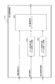
図4を参照して、画像変換部104の1実施例について説明する。
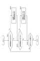
図4に示す画像変換部104は、3種類の画像変換方法を実行する第1〜第3の2D−3D変換部202〜204を並列に有する。
処理対象画像の奥行情報信頼度に応じて、これら3つの第1〜第3の2D−3D変換部202〜204における変換画像のいずれかを選択、または合成して出力画像を生成する。
[4. Configuration and processing of image conversion unit]
Next, details of processing executed by the
(4-1. First Example of Image Conversion Unit)
With reference to FIG. 4, an embodiment of the
The
Depending on the depth information reliability of the processing target image, one of these three converted images in the first to third 2D-
なお、以下に説明する実施例では、処理対象画像となる1画像全体での信頼度に応じて、処理を切り替える設定として説明するが、画素毎、あるいは複数画素からなるブロック単位の信頼度に応じて、画素単位あるいはブロック単位で処理を切り替える設定としてもよい。 In the embodiment described below, processing is described as a setting for switching processing according to the reliability of the entire image to be processed, but depending on the reliability of each pixel or block unit composed of a plurality of pixels. Thus, the process may be set to be switched in units of pixels or blocks.
入力画像前処理部201は、画像入力部101から処理対象画像の画像信号を入力して各2D−3D変換部202〜204へ画像信号を出力する。
第1の2D−3D変換部202は、奥行情報出力部102の出力する奥行情報を主体的に利用し、2次元画像を奥行情報から幾何学的に演算し、3次元画像表示に適用する左眼用画像と右眼用画像からなる左右視差画像を生成する。すなわち、奥行情報に基づく幾何学的2D−3D変換処理を実行する。
The input
The first 2D-
2D画像と奥行情報から幾何学的、すなわち座標変換や射影により左右視差画像を生成する方法については既に一般的であり特に説明しないが、例えば、先に説明した特許文献9(特開2009−296272号公報)にも原理と変換方法が記述されており、第1の2D−3D変換部202では、例えばこれらの方法を適用して奥行情報を主体的に適用した幾何学的2D−3D変換処理を実行する。
A method of generating a right-and-left parallax image geometrically from a 2D image and depth information, that is, coordinate conversion or projection is already common and will not be particularly described. For example, Patent Document 9 described above (Japanese Patent Laid-Open No. 2009-296272). The first 2D-
第2の2D−3D変換部203は、奥行情報出力部102の出力する奥行情報を補助的に利用して、処理対象画像として入力する2次元画像を3次元画像表示に適用する左眼用画像と右眼用画像からなる左右視差画像を生成する。すなわち、奥行情報を補助的に利用した幾何学的でない変換を実行する。
The second 2D-
基本的には、構図解析を用いる方法や、エッジ成分、周波数成分等を用いる方法など奥行情報を適用せずに2次元画像を3次元画像表示に適用する左眼用画像と右眼用画像からなる左右視差画像を生成する。例えば、先に説明した特許文献8(特開2010−63083号公報)には、周波数成分を用いた左右視差画像の生成方法が記述されており、第2の2D−3D変換部203では、例えばこれらの方法を適用して奥行情報を用いずに左右視差画像を生成する。さらに、奥行情報出力部102の出力する奥行情報を利用して視差量や効果のレベルを微調整する。
Basically, a left-eye image and a right-eye image that apply a two-dimensional image to a three-dimensional image display without applying depth information such as a method using composition analysis, a method using an edge component, a frequency component, etc. A left-right parallax image is generated. For example, Patent Document 8 (Japanese Patent Laid-Open No. 2010-63083) described above describes a method for generating a left-right parallax image using a frequency component. In the second 2D-
第3の2D−3D変換部204は、奥行情報出力部102の出力する奥行情報を全く利用せずに、処理対象画像として入力する2次元画像のみから3次元画像表示に適用する左眼用画像と右眼用画像からなる左右視差画像を生成する。
The third 2D-
具体的には、上述の構図解析を用いる方法や、エッジ成分、周波数成分等を用いる方法などを適用する。先に説明した特許文献8(特開2010−63083号公報)に記載の周波数成分を用いた左右視差画像の生成方法を適用してもよい。第3の2D−3D変換部204では、例えばこれらの方法を適用して奥行情報を用いない2D−3D変換処理を実行する。
Specifically, a method using the composition analysis described above, a method using an edge component, a frequency component, or the like is applied. You may apply the production method of the right-and-left parallax image using the frequency component of the patent document 8 (Unexamined-Japanese-Patent No. 2010-63083) demonstrated previously. The third 2D-
それぞれの2D−3D変換部202〜204で生成した左右視差画像は画像選択部205に入力される。一方、奥行情報信頼度出力部103からは、処理対象画像である2次元画像に設定された奥行情報の信頼度情報も画像選択部205に入力される。
The left and right parallax images generated by the respective 2D-
画像選択部205は、信頼度情報(一例として信頼度高7から信頼度低0)に応じて、例えば、以下の画像選択処理により出力画像の選択を実行する。
信頼度が6以上であれば、第1の2D−3D変換部202の生成した奥行情報を適用した幾何学的変換による左右視差画像を選択する。
信頼度が2以下であれば第3の2D−3D変換部204の生成した奥行情報を利用しない変換で求めた左右視差画像を選択する。
信頼度が6〜2の範囲の場合は、第2の2D−3D変換部203の生成した奥行情報を補助的に利用した幾何学的でない2D−3D変換により生成した左右視差画像を選択する。
The
If the reliability is 6 or more, a left-right parallax image by geometric transformation to which the depth information generated by the first 2D-
If the reliability is 2 or less, the left and right parallax images obtained by the conversion that does not use the depth information generated by the third 2D-
When the reliability is in the range of 6 to 2, the left and right parallax images generated by non-geometric 2D-3D conversion using the depth information generated by the second 2D-
なお、上述の処理例では、処理対象となる画像全体の信頼度情報に基づいて処理を選択する例を説明したが、例えば画素単位あるいはブロック単位の信頼度を利用した画素やブロック単位の選択処理を実行する構成としてもよい。
この場合には、各画素またはブロック単位の信頼度に応じて、各画素またはブロック単位で、第1〜第3の2D−3D変換部の出力を所定の割合で重み付けしてブレンドするといった処理を実行して出力画像を生成する。
また図4に示す画像変換部では、2D−3D変換部の実行する処理態様を3つの種類とした例を説明したが、3種に限定するものでなく、2種や4種以上の変換方法を設定して、奥行情報の信頼度に応じて出力を選択する構成としてもよい。
In the above-described processing example, an example in which processing is selected based on reliability information of the entire image to be processed has been described. For example, pixel or block unit selection processing using pixel-level or block-unit reliability It is good also as a structure which performs.
In this case, according to the reliability of each pixel or block unit, a process of weighting and blending the outputs of the first to third 2D-3D conversion units at a predetermined ratio for each pixel or block unit is performed. Run to generate an output image.
In the image conversion unit illustrated in FIG. 4, the example in which the processing modes executed by the 2D-3D conversion unit are three types has been described. However, the image conversion unit is not limited to three types, but two or four or more conversion methods. It is good also as a structure which selects and outputs according to the reliability of depth information.
画像選択部205から出力された画像データは、出力画像後処理部206に入力され、後段の画像出力部に適した画像データ形式へ変換される。なお、出力画像後処理部206は、必須構成ではなく、後段の画像出力部が解釈可能であれば省略した構成も可能である。
The image data output from the
(4−2.画像変換部の第2実施例について)
図4を参照して説明した画像変換部104は、奥行情報の信頼度に応じて、異なる2D−3D変換処理により生成した画像を選択、または合成する処理を実行していた。画像変換部の構成は、この図4に示す構成に限らず、例えば図5に示す構成としてもよい。
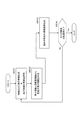
(4-2. Second Embodiment of Image Conversion Unit)
The
図5は、本発明の画像変換部のもう1つの実施例を示すブロック図である。先に説明した図4の画像変換部104の構成では、3種の画像変換方法が完全に独立して並列に存在し、例えば画像全体の奥行情報信頼度に応じて処理を切り替える設定としていた。
FIG. 5 is a block diagram showing another embodiment of the image conversion unit of the present invention. In the configuration of the
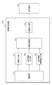
図5に示す画像変換部310は、図4に示す処理構成と異なり、並列に異なる2D−3D変換処理を行う必要がない。図5に示す画像変換部300は、処理対象となる2次元画像の空間的な特徴量を抽出し(視差強調成分)、その視差強調成分を用いて、3次元画像表示に適用する左眼用画像(L画像)と右眼用画像(R画像)を生成する。
Unlike the processing configuration shown in FIG. 4, the
すなわち、入力2次元画像に対して、視差強調成分を適用した異なる強調処理を施すという処理によりLR画像を生成する。なお、この視差強調成分を適用したLR画像生成処理については、例えば特許文献8(特開2010−63083号公報)に記載がある。特許文献8に記載の処理について簡単に説明する。まず、処理対象となる2次元画像の入力画像信号を微分した信号を視差強調成分として抽出する。すなわち、画像変換部に入力された画像データを輝度信号をとクロマ信号に分離し、輝度、クロマ信号それぞれに対する微分信号(H)を生成する。具体的には、画像の輝度、クロマ信号を水平方向に入力して、入力信号を一次微分した信号を生成する。一次微分処理は、例えば、水平方向3タップの線形1次微分フィルタなどを用いる。その後、微分信号(H)を非線形的に変換して、最終的な視差強調信号(E)を得ている。
この視差強調信号(E)とオリジナルの入力画像信号Sを用いて、左右視差画像としてのR画像とL画像信号の各画像信号R、Lを、以下の式によって生成する。
R=S−E
L=S+E
このようにオリジナル画像信号に対して、視差強調信号(E)の加算または減算によって3次元画像表示に適用するL画像とR画像を生成する。
In other words, an LR image is generated by a process of applying different enhancement processing to which the parallax enhancement component is applied to the input two-dimensional image. Note that the LR image generation processing to which the parallax enhancement component is applied is described in, for example, Japanese Patent Application Laid-Open No. 2010-63083. The process described in Patent Document 8 will be briefly described. First, a signal obtained by differentiating an input image signal of a two-dimensional image to be processed is extracted as a parallax enhancement component. That is, the image data input to the image conversion unit is separated into a luminance signal and a chroma signal, and a differential signal (H) for each of the luminance and the chroma signal is generated. Specifically, the luminance of an image and a chroma signal are input in the horizontal direction, and a signal obtained by first-order differentiation of the input signal is generated. For example, a linear primary differential filter with 3 taps in the horizontal direction is used for the primary differential processing. Thereafter, the differential signal (H) is nonlinearly converted to obtain a final parallax enhancement signal (E).
Using the parallax enhancement signal (E) and the original input image signal S, the image signals R and L of the R image and the L image signal as left and right parallax images are generated by the following equations.
R = SE
L = S + E
In this way, an L image and an R image to be applied to three-dimensional image display are generated by adding or subtracting the parallax enhancement signal (E) to the original image signal.
図5に示す画像変換部310の処理について説明する。
入力画像前処理部311は、画像入力部101からの入力画像信号を視差強調成分算出部312に出力する。
視差強調成分算出部312は、左右視差画像を生成するための視差強調成分を抽出し、成分量制御部315へ出力する。前述したように視差強調成分とは、例えば特許文献8(特開2010−63083号公報)に記載の構成を適用する場合には、画像信号の微分信号(H)となる。その他の成分情報を利用する構成としてもよい。
Processing of the
The input
The parallax enhancement
成分量制御部315は、処理対象画像に対する処理画素単位で視差強調成分を入力し、入力した視差強調成分量に対して微調整を行う。特許文献8(特開2010−63083号公報)に記載の方法を適用する場合、成分量制御部315は、微分信号(H)を非線形的に変換して、最終的な視差強調信号(E)を算出する処理を行う。
その後、視差画像生成部316は、左右視差画像としての左眼用画像(L画像)と右眼用画像(R画像)を生成する。
The component
Thereafter, the parallax
図5に示す画像変換部310の奥行補間部313は、奥行情報出力部102の出力する奥行情報を入力する。奥行補間部313は、奥行情報出力部102の出力する奥行情報を処理対象画像である2次元画像の各画素対応の情報に設定する。入力画像の画素と1対1対応でない場合には、例えばBi Cubic法などの補間方法により、各画素位置の奥行情報を算出し、成分量制御部315へ出力する。
The
成分量制御部315は、視差成分量の微調整を実行する。
例えば、特許文献8(特開2010−63083号公報)に記載の構成を適用する場合、視差強調信号(E)とオリジナルの入力画像信号(S)を用いて、左右視差画像としてのR画像とL画像信号の各画像信号R、Lは、以下の式によって生成される。
R=S−E
L=S+E
成分量制御部315は、各画素対応の奥行値に基づいて、大きな視差を設定する場合はEを大きく、視差を小さく設定する場合はEを小さくする調整を実行する。
この調整処理によって視差成分量の微調整を実行する。
The component
For example, when the configuration described in Patent Document 8 (Japanese Patent Laid-Open No. 2010-63083) is applied, an R image as a left / right parallax image is obtained using a parallax enhancement signal (E) and an original input image signal (S). Each image signal R, L of the L image signal is generated by the following equation.
R = SE
L = S + E
Based on the depth value corresponding to each pixel, the component
By this adjustment process, fine adjustment of the parallax component amount is executed.
すなわち、奥行値に応じて、視差強調信号(E)の大きさを変えてやれば、視差量の微調整が可能となる。すなわち、非線形変換前に、微分信号(H)に予め設定した規則に則った係数(ゲイン係数)を乗じることで、微分信号の振幅値を制御し、微分信号の補正信号である補正微分信号(H')を生成するように変更する。その後、補正微分信号(H')を非線形的に変換して、最終的な視差強調信号(E)を得るようにする。 That is, if the magnitude of the parallax enhancement signal (E) is changed according to the depth value, the amount of parallax can be finely adjusted. That is, before nonlinear conversion, the differential signal (H) is multiplied by a coefficient (gain coefficient) according to a preset rule to control the amplitude value of the differential signal, and a corrected differential signal (correction signal of the differential signal) H ′) is generated. Thereafter, the corrected differential signal (H ′) is nonlinearly converted to obtain a final parallax enhancement signal (E).
なお、上記の処理例は、特許文献8(特開2010−63083号公報)に記載の構成を適用した場合の処理例であるが、他の方法の場合でも、成分量制御部で、2D画像から抽出した視差成分量(特徴量)に奥行値に応じたゲインをかける方法により、視差量の微調整は可能である。 The above processing example is a processing example in the case where the configuration described in Patent Document 8 (Japanese Patent Laid-Open No. 2010-63083) is applied. The amount of parallax can be finely adjusted by applying a gain corresponding to the depth value to the amount of parallax components (features) extracted from
本発明ではさらに、処理対象画像に対応して取得または算出された奥行情報の信頼度情報を加味した処理を行う。
奥行情報信頼度出力部103から入力される信頼度情報は、信頼度補間部314へ入力される。信頼度補間部314は、信頼度情報についても画素対応の奥行情報と1対1の情報とする処理を行う。例えばBi Cubic法などの補間方法により、各画素位置の信頼度情報を算出する。
In the present invention, further, processing is performed in consideration of reliability information of depth information acquired or calculated corresponding to the processing target image.
The reliability information input from the depth information
各画素対応の信頼度情報は、成分量制御部315へ出力される。成分量制御部315は、信頼度情報に基づいて視差成分量に対して乗算するゲイン量を設定する。奥行き値が信頼できない場合のゲイン値0から信頼できる場合のゲイン値1までを設定する。成分量制御部315は、視差成分量に対しこのゲイン値をさらに乗算すれば、奥行が信頼できない場合は視差強調成分量を減らし、無理に視差成分を付けないようにすることが可能となる。
The reliability information corresponding to each pixel is output to the component
すなわち、特許文献8(特開2010−63083号公報)に記載の構成を適用した場合、奥行値の信頼度に応じて、視差強調信号(E)の大きさを変えることで視差量の微調整を行う。非線形変換前に、微分信号(H)に、信頼度情報に基づいて算出した係数(ゲイン係数)を乗じることで、微分信号の振幅値を制御し、微分信号の補正信号である補正微分信号(H')を生成するように変更する。その後、補正微分信号(H')を非線形的に変換して、最終的な視差強調信号(E)を得るようにする。 That is, when the configuration described in Patent Document 8 (Japanese Patent Laid-Open No. 2010-63083) is applied, the amount of parallax is finely adjusted by changing the magnitude of the parallax enhancement signal (E) according to the reliability of the depth value. I do. Prior to nonlinear conversion, the differential signal (H) is multiplied by a coefficient (gain coefficient) calculated based on the reliability information to control the amplitude value of the differential signal, and a corrected differential signal (correction signal of the differential signal) H ′) is generated. Thereafter, the corrected differential signal (H ′) is nonlinearly converted to obtain a final parallax enhancement signal (E).
この特許文献8(特開2010−63083号公報)に記載の構成以外の構成を採用した場合でも、成分量制御部315において、2D画像から抽出した視差成分量に奥行値の信頼度に応じたゲインを乗算する方法により、視差量の微調整は可能である。なお、成分量制御部315の構成例については図7を用いて後述する。
Even when a configuration other than the configuration described in Patent Document 8 (Japanese Patent Laid-Open No. 2010-63083) is employed, the component
成分量制御部315で最終的に求められたある画素での視差強調成分は、視差画像生成部316へ出力される。視差画像生成部316では、入力画像前処理部311から出力された2次元画像と成分量制御部315から入力する視差強調成分を利用して左右視差画像を生成し、出力画像後処理部317に出力する。
The parallax enhancement component at a certain pixel finally obtained by the component
視差画像生成部316の実行する処理は、特許文献8(特開2010−63083号公報)に記載の構成を適用した場合、入力画像前処理部311から入力する2次元画像信号(S)、成分量制御部315から入力する視差強調信号(E)を用いて、左右視差画像としてのR画像とL画像信号の各画像信号R、Lを、以下の式によって生成する処理となる。
R=S−E
L=S+E
ただし、ここで、視差強調信号(E)は奥行き情報の信頼度に応じて調整された値となる。
The processing executed by the parallax
R = SE
L = S + E
However, the parallax enhancement signal (E) is a value adjusted according to the reliability of the depth information.
(4−3.画像変換部の第3実施例について)
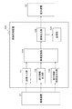
図6は、本発明の画像変換部のもう1つの実施例を示すブロック図である。図6に示す画像変換部320も、図5を参照して説明した画像変換部と同様、図4に示す処理構成と異なり、並列に異なる2D−3D変換処理を行う必要がない。
図5を参照して説明した画像変換部310は、奥行情報を補助的に用いる構成であったが、図6に示す画像変換部320は、奥行情報を主体的に用いる(2次元画像からは奥行は推定しない)場合の構成例である。
(4-3. Third Example of Image Conversion Unit)
FIG. 6 is a block diagram showing another embodiment of the image conversion unit of the present invention. Similar to the image conversion unit described with reference to FIG. 5, the
The
図6に示す画像変換部320の処理について説明する。
図6に示す画像変換部320の奥行補間部322は、奥行情報出力部102の出力する奥行情報を入力する。奥行補間部322は、奥行情報出力部102の出力する奥行情報を処理対象画像である2次元画像の各画素対応の情報に設定する。入力画像の画素と1対1対応でない場合には、例えばBi Cubic法などの補間方法により、各画素位置の奥行情報を算出し、奥行制御部324へ出力する。
Processing of the
The
奥行情報信頼度出力部103から入力される信頼度情報は、信頼度補間部323へ入力される。信頼度補間部323は、信頼度情報についても画素対応の奥行情報と1対1の情報とする処理を行う。例えばBi Cubic法などの補間方法により、各画素位置の信頼度情報を算出する。各画素対応の信頼度情報は、奥行制御部324出力される。
The reliability information input from the depth information
奥行制御部324は、入力画像前処理部321から処理対象画像の各画素データを入力し、処理画素に対応する奥行情報と信頼度情報をそれぞれ奥行補間部322と信頼度補間部323から入力する。
奥行制御部324は、入力された奥行情報に対して信頼度情報を用いて奥行(視差量)の増減を行う。一例として、信頼度情報を信頼できない場合のゲイン値0から信頼できる場合のゲイン値1までと仮定し、視差量に対しこのゲイン値をさらに乗算するなどして、信頼できない場合は視差量を減らし、無理に視差を付けないようにする。
The
The
奥行制御部324で最終的に求められたある画素での奥行(視差量)は、幾何学的視差画像生成部325へ出力される。幾何学的視差画像生成部325では、入力画像前処理部321から出力された2次元画像と、奥行制御部324から入力する視差量に基づいて幾何学的に左右視差画像を生成し、出力画像後処理部326に出力する。
The depth (parallax amount) at a certain pixel finally obtained by the
なお、画像変換部の構成例について、図4、図5、図6の3種類について説明したが、いずれの構成においても、出力画像は、左右視差画像を生成する時に、左右視差画像同時生成、左眼用画像だけ、右眼用画像だけの3種類の中から選択可能である。 The configuration example of the image conversion unit has been described with respect to the three types of FIGS. 4, 5, and 6. In any configuration, the output image is generated when the left and right parallax images are generated simultaneously. It is possible to select from the three types of only the image for the left eye and only the image for the right eye.
[5.成分量制御部の処理について]
次に、図5に示す第2実施例に係る画像変換部310内に設定された成分量制御部315の実行する処理について詳細に説明する。
図7は、成分量制御部315の一実施例の構成を示すブロック図である。成分量制御部315では、入力された視差強調成分信号の振幅値を、同じく入力した奥行情報、信頼度情報を基に、その振幅値を制御する。なお、以下に説明する実施例では、奥行情報とその信頼度情報は入力画像信号のある1画素に対応した視差強調成分1画素毎に、1つの値を有する状態で入力されるものとして説明していく。
[5. About processing of the component amount control unit]
Next, processing executed by the component
FIG. 7 is a block diagram illustrating a configuration of an example of the component
成分量制御部315に入力されたある画素の奥行情報Dは、ゲイン係数算出部351に入力され、後段の処理のため、奥行情報Dに予め設定した関数f(x)を用いて0から1までのある値のゲイン係数βに変換され成分量調整部353に出力される。
β=f(D)
Depth information D of a certain pixel input to the component
β = f (D)
同様に、成分量制御部315に入力されたある画素の信頼度情報Sは、ゲイン係数算出部352に入力され、後段の処理のため、信頼度情報Sに予め設定した関数g(x)を用いて0から1までのある値のゲイン係数γに変換され成分量調整部353に出力される。
γ=g(S)
Similarly, the reliability information S of a certain pixel input to the component
γ = g (S)
成分量調整部353は、視差強調成分算出部312からある画素の視差強調成分αを入力し、奥行情報ゲイン係数β、信頼度情報ゲイン係数γとを用いて、最終的な視差強調成分α'を以下の式で変換して出力する。
α'=α×β×γ
The component
α '= α × β × γ
ここでゲイン係数値は便宜上0〜1としたが、ある統一されたルールに従っていればよく、この範囲に特定するものではない。
また、関数f(x),g(x)は、様々な設定が利用可能である。
関数f(x)、g(x)の一例としては、例えば、
f(x)=A×x(ただしAは定数)
g(x)=B×x(ただしBは定数)
上記式に示されるような線形一次関数を用いる。A、Bは予め設定した定数であり、様々な値に設定可能である。
また、ゲイン係数算出部における変換関数は、線形一次関数に限定するものではなく、また非線形的な変換を施しても構わない。
Here, the gain coefficient value is set to 0 to 1 for the sake of convenience. However, the gain coefficient value only needs to follow a certain unified rule, and is not specified within this range.
Various settings can be used for the functions f (x) and g (x).
As an example of the functions f (x) and g (x), for example,
f (x) = A × x (where A is a constant)
g (x) = B × x (B is a constant)
A linear linear function as shown in the above equation is used. A and B are preset constants and can be set to various values.
Further, the conversion function in the gain coefficient calculation unit is not limited to a linear linear function, and a non-linear conversion may be performed.
また一例として、ゲイン値を用いるのではなく、信頼度が低い奥行情報の場合には、その奥行情報を使用せず、その画素の近傍の奥行情報を用いて、単純に平均値を求めたり、縦、横、斜め方向の相関を求め、相関の強いものだけを選択して平均値を求めるなどの方法で値を算出し、オリジナルの奥行値と差し換えて視差強調成分を調整するなどの手法もある。 In addition, as an example, instead of using a gain value, in the case of depth information with low reliability, the depth information is not used, and the average value is simply obtained using the depth information in the vicinity of the pixel, There are also methods such as obtaining the correlation in the vertical, horizontal, and diagonal directions, selecting only those with strong correlation and calculating the average value, and adjusting the parallax enhancement component by replacing it with the original depth value. is there.
[6.奥行制御部の処理について]
次に、先に図6を参照して説明した第3実施例に係る画像変換部320の内部に設定される奥行制御部324の実行する処理について詳細に説明する。
図8は、奥行制御部324の一実施例の構成を示すブロック図である。奥行制御部324では、奥行補間部322から入力された奥行情報の振幅値を、信頼度補間部323から同じく入力した信頼度情報を基に、その振幅値を制御する。
なお、以下に説明する実施例では、奥行情報とその信頼度情報は、奥行情報の1データ毎に、1つの値を有する状態で入力されるものとして説明していく。
[6. Depth control unit processing]
Next, processing executed by the
FIG. 8 is a block diagram illustrating a configuration of an embodiment of the
In the embodiment described below, the depth information and the reliability information thereof are described as being input in a state having one value for each data of the depth information.
奥行制御部324に入力されたある画素の信頼度情報Sは、ゲイン係数算出部371に入力され、後段の処理のため、信頼度情報Sに予め設定した関数g(x)を用いて0から1までのある値のゲイン係数γに変換され奥行調整部372に出力される。
γ=g(S)
The reliability information S of a certain pixel input to the
γ = g (S)
奥行制御部324に入力されたある画素の奥行情報Dは、信頼度情報ゲイン係数γとを用いて、最終的な奥行情報D'を以下の式で変換して出力する。
D'=D×γ
The depth information D of a certain pixel input to the
D ′ = D × γ
ここでゲイン係数値は便宜上0〜1としたが、ある統一されたルールに従っていればよく、この範囲に特定するものではない。
また、f(x),g(x)は、様々な設定が利用可能である。
関数g(x)の一例としては、例えば、
g(x)=B×x(ただしBは定数)
上記式に示されるような線形一次関数を用いる。Bは予め設定した定数であり、様々な値に設定可能である。
また、ゲイン係数算出部における変換関数は、線形一次関数に限定するものではなく、また非線形的な変換を施しても構わない。
Here, the gain coefficient value is set to 0 to 1 for the sake of convenience. However, the gain coefficient value only needs to follow a certain unified rule, and is not specified within this range.
Various settings can be used for f (x) and g (x).
As an example of the function g (x), for example,
g (x) = B × x (B is a constant)
A linear linear function as shown in the above equation is used. B is a preset constant and can be set to various values.
Further, the conversion function in the gain coefficient calculation unit is not limited to a linear linear function, and a non-linear conversion may be performed.
また一例として、ゲイン値を用いるのではなく、信頼度が低い奥行情報の場合には、その奥行情報を使用せず、その画素の近傍の奥行情報を用いて、単純に平均値を求めたり、縦、横、斜め方向の相関を求め、相関の強いものだけを選択して平均値を求めるなどの方法で値を算出し、オリジナルの奥行値と差し換えて奥行値を調整するなどの手法もある。 In addition, as an example, instead of using a gain value, in the case of depth information with low reliability, the depth information is not used, and the average value is simply obtained using the depth information in the vicinity of the pixel, There are also methods such as obtaining the correlation in the vertical, horizontal and diagonal directions, calculating the value by selecting only the strong correlation and calculating the average value, and adjusting the depth value by replacing it with the original depth value. .
[7.視差画像生成部の処理について]
次に図5を参照して説明した第2実施例に係る画像変換部310内の視差画像生成部316の処理について説明する。
視差画像生成部316は、処理対象となるオリジナルの2次元入力画像と、この画像から生成した空間的な特徴量、すなわち、成分量制御部315から入力する視差強調成分信号を適用して左眼用画像(L画像)と、右眼用画像(R画像)を生成する処理を行う。
[7. Processing of the parallax image generation unit]
Next, processing of the parallax
The parallax
視差画像生成部316は、オリジナルの2次元入力画像と視差強調成分を用いて、例えば先に説明した特許文献8(特開2010−63083号公報)に記載の構成を適用した場合、入力画像前処理部311から入力する2次元画像信号(S)、成分量制御部315から入力する視差強調信号(E)を用いて、左右視差画像としてのR画像とL画像信号の各画像信号R、Lを、以下の式によって生成する処理となる。
R=S−E
L=S+E
The parallax
R = SE
L = S + E
[8.幾何学的視差画像生成部の処理について]
次に図6に示す第3実施例に係る画像変換部320の内部に構成される幾何学的視差画像生成部325の処理について説明する。
幾何学的視差画像生成部325は、オリジナルの2次元入力画像と、この画像に対応する奥行情報を用いて幾何学的演算で左眼用画像(L画像)と、右眼用画像(R画像)を生成する処理を行う。
幾何学的視差画像生成部325は、オリジナルの2次元入力画像と奥行情報を用いる方法を適用して左眼用画像(L画像)と、右眼用画像(R画像)を生成する。ただし、適用する奥行き情報は、信頼度に応じて制御された値となる。
[8. About processing of geometric parallax image generation unit]
Next, processing of the geometric parallax
The geometric parallax
The geometric parallax
[9.画像表示装置に関連した処理について]
図1、図2に示す本発明の画像処理装置の出力は、図1,2に示す表示装置52において表示される。最終的に画像表示を実行する表示装置の表示方式としては、例えば以下の種類がある。
(1)左眼用画像と右眼用画像を時間分割で交互に出力する方式
これは、例えば液晶シャッタを左右交互に開閉して観察する画像を左右の眼交互に時間的に分離するアクティブ眼鏡方式に対応する画像出力方式である。(時間的にLR画像を切り替える方式)
(2)左眼用画像と右眼用画像を空間的に分離して同時出力する方式
これは、例えば偏光フィルタや、色フィルタにより左右の眼各々によって観察する画像を分離するパッシブ眼鏡方式に対応する画像出力方式である。
例えば、この空間分割方式の立体表示装置においては、表示前面に水平ラインごとに偏光方向が異なるように設定した偏光フィルタを貼り合わせ、ユーザが装着する偏光フィルタ方式によるメガネで見た場合に、左眼と右眼に水平ラインごとに映像が分離されて観察される。(空間的にLR画像を切り替える方式)
[9. Processing related to image display device]
The output of the image processing apparatus of the present invention shown in FIGS. 1 and 2 is displayed on the
(1) A method of alternately outputting a left-eye image and a right-eye image in a time-division manner. This is, for example, active spectacles that temporally separate an image to be observed by alternately opening and closing a liquid crystal shutter to the left and right eyes. This is an image output method corresponding to the method. (Method to switch LR image temporally)
(2) A method for spatially separating the left-eye image and the right-eye image and outputting them simultaneously. This corresponds to, for example, a polarizing spectacle filter or a passive spectacle method that separates images to be observed by the left and right eyes with a color filter. This is an image output method.
For example, in this spatial division type stereoscopic display device, when a polarizing filter set so that the polarization direction is different for each horizontal line is pasted on the front surface of the display, and when viewed with the polarizing filter type glasses worn by the user, Images are observed separately for each horizontal line in the eyes and right eye. (Spatial LR image switching method)
図1、図2に記載した画像処理装置100において、上記の様々な方式に従った画像表示を実行する表示装置に出力するデータ生成処理例について説明する。
In the
まず、最終的に画像表示を実行する表示装置の表示方式が、左眼用画像と右眼用画像を時間的に分割して交互出力する方式である場合の画像変換部の処理例について説明する。 First, a processing example of the image conversion unit when the display method of the display device that finally performs image display is a method in which the left-eye image and the right-eye image are temporally divided and alternately output will be described. .
この時分割画像表示方式の場合、画像変換部は、入力画像データの各フレーム(フレームn,n+1,n+2,n+3・・・)について、左眼用画像と右眼用画像を各フレーム毎に切り替えて生成して出力する。なお、具体的な処理シーケンスについては、後段でフローチャート(図15)を参照して説明する。 In this time-division image display method, the image conversion unit switches the left-eye image and the right-eye image for each frame for each frame (frames n, n + 1, n + 2, n + 3...) Of the input image data. Generated and output. A specific processing sequence will be described later with reference to a flowchart (FIG. 15).
画像変換部104は、入力する画像データの奇数フレームと偶数フレームをそれぞれ左眼用画像および右眼用画像(または、右眼用画像および左眼用画像)としフレーム毎に変換設定を切り替えるように制御して出力する。出力画像は、図1、図2に示す画像出力部105を介して画像表示装置52に左眼用画像と右眼用画像が時間分割で交互出力される。
この方式では、画像変換部104は、各フレームに対応して右眼用画像または左眼用画像の1画像を生成して出力することになる。すなわち1系統の画像データを出力する。
The
In this method, the
次に、最終的に画像表示を実行する表示装置の表示方式が、左眼用画像と右眼用画像を空間的に分割して交互出力する方式である場合の画像変換部の処理例について説明する。
この空間分割画像表示方式の場合、画像変換部104は、入力画像データの各ライン(ラインn,n+1,n+2,n+3・・・)について、左眼用画像と右眼用画像を各ライン毎に切り替えて生成して出力する。なお、具体的な処理シーケンスについては、後段でフローチャート(図14)を参照して説明する。
Next, a description will be given of a processing example of the image conversion unit when the display method of the display device that finally performs image display is a method of spatially dividing the left-eye image and the right-eye image and alternately outputting them. To do.
In the case of this space-divided image display method, the
画像変換部104は、入力する画像データの奇数ラインと偶数ラインをそれぞれ左眼用画像および右眼用画像(または、右眼用画像および左眼用画像)としてライン毎に変換設定を切り替えるように制御されながら出力する。出力画像は、画像出力部105を介して画像表示装置52に左眼用画像と右眼用画像が空間分割で交互出力される。
この方式では、画像変換部104は、各ラインに対応して右眼用画像または左眼用画像の1画像を生成して出力することになる。
The
In this method, the
[10.画像変換部の処理シーケンスについて]
次に、図9以下のフローチャートを参照して本発明の画像処理装置において実行する画像変換処理のシーケンスについて説明する。
[10. About processing sequence of image converter]
Next, a sequence of image conversion processing executed in the image processing apparatus of the present invention will be described with reference to the flowchart in FIG.
(10−1.図4に示す第1実施例の画像変換部を適用した処理シーケンス)
まず、図4に示す画像変換部を適用した処理シーケンスについて、図9〜図11に示すフローチャートを参照して説明する。
図9に示すフローチャートを参照して、図4に示す第1実施例の画像変換部を適用した処理シーケンスの一実施例について説明する。
信頼度情報は、処理対象とする入力2次元画像の1枚単位とした設定や、画像の画素単位やブロック単位等の領域(エリア)単位とした設定等が可能である。
(10-1. Processing sequence to which the image conversion unit of the first embodiment shown in FIG. 4 is applied)
First, a processing sequence to which the image conversion unit shown in FIG. 4 is applied will be described with reference to the flowcharts shown in FIGS.
With reference to the flowchart shown in FIG. 9, an example of a processing sequence to which the image conversion unit of the first example shown in FIG. 4 is applied will be described.
The reliability information can be set as a single unit of the input two-dimensional image to be processed, or set as a region (area) unit such as a pixel unit or a block unit of the image.
まず、ステップS101において、撮像装置において通常通りの画像の撮像が行われる。奥行情報が撮像時に生成される場合はそれを用い、生成されない場合は推定により奥行情報を生成する。撮像時の条件や、推定により入力画像に画像または領域単位の信頼度情報を生成する。なお、本例では、信頼度情報は、奥行情報が、
(a)完全に信頼できる
(b)ある程度信頼できる
(c)上記(a),(b)以外=信頼できない
これらの3値であるとする。
なお、これらの区別は、信頼度情報を予め規定した閾値によって区分することで実行可能である。
First, in step S101, an image is picked up as usual in the image pickup apparatus. If depth information is generated at the time of imaging, it is used, and if not generated, depth information is generated by estimation. Reliability information for each image or area is generated in the input image based on conditions at the time of imaging or estimation. In this example, the reliability information is depth information,
(A) Completely reliable (b) Reliable to some extent (c) Other than the above (a) and (b) = Unreliable These three values are assumed.
These distinctions can be performed by classifying the reliability information according to a predetermined threshold value.
奥行情報が完全に信頼できる場合は、ステップS102の判定がYesとなり、ステップS103に進み、奥行情報主体(幾何学的)の2D−3D変換処理を行い、左右視差画像を生成する。図4の画像変換部104の第1の2D−3D変換部202の処理に相当する処理である。
If the depth information is completely reliable, the determination in step S102 is yes, and the process proceeds to step S103, where the 2D-3D conversion process of the depth information main (geometric) is performed to generate a left-right parallax image. This process corresponds to the process of the first 2D-
奥行情報が信頼できない場合は、ステップS102とステップS104の判定がNoとなり、ステップS106に進み、奥行情報を全く使用しない2D−3D変換処理を行い、左右視差画像を生成する。図4の画像変換部104の第3の2D−3D変換部204の処理に相当する処理である。
If the depth information is unreliable, the determinations in step S102 and step S104 are No, and the process proceeds to step S106 to perform 2D-3D conversion processing that does not use the depth information at all, and generate right and left parallax images. This process corresponds to the process of the third 2D-
奥行情報がある程度しか信頼できない場合は、ステップS102の判定がNo、ステップS104の判定がYesとなり、ステップS105に進み、奥行情報を補助的に使用する2D−3D変換処理を行い、左右視差画像を生成する。図4の画像変換部104の第2の2D−3D変換部203の処理に相当する処理である。
If the depth information can be trusted only to some extent, the determination in step S102 is No, the determination in step S104 is Yes, and the process proceeds to step S105 to perform 2D-3D conversion processing that uses the depth information in an auxiliary manner, thereby Generate. This process corresponds to the process of the second 2D-
奥行情報の信頼度に応じて、ステップS103、S105、S106のいずれかの2D−3D変換処理が実行された後、ステップS107において未処理データの有無が判定される。未処理データがある場合は、未処理データに対してステップS101以下の処理を実行する。ステップS107において、すべてのデータに対する処理が終了したと判定されると処理を終了する。 After the 2D-3D conversion process in any one of steps S103, S105, and S106 is executed according to the reliability of the depth information, the presence or absence of unprocessed data is determined in step S107. If there is unprocessed data, the processing from step S101 is executed on the unprocessed data. If it is determined in step S107 that the processing for all data has been completed, the processing ends.
図10は信頼度情報の判断が2値である場合の処理シーケンスを説明するフローチャートである。すなわち、信頼度情報は、奥行情報が、
(a)完全に信頼できる
(b)上記(a)以外=完全に信頼できるとは言えない
これらの2値であるとする。
このフローに従った処理は、例えば奥行情報の信頼度が高い場合が多い際に適した処理である。
FIG. 10 is a flowchart for explaining a processing sequence when the reliability information is judged to be binary. That is, the reliability information is the depth information,
(A) Fully reliable (b) Other than the above (a) = It cannot be said that it is completely reliable.
The process according to this flow is a process suitable when the reliability of the depth information is often high, for example.
まず、ステップS201において、撮像装置において通常通りの画像の撮像が行われる。奥行情報が撮像時に生成される場合はそれを用い、生成されない場合は推定により奥行情報を生成する。撮像時の条件や、推定により入力画像に画像または領域単位の信頼度情報を生成する。なお、本例では、信頼度情報は、奥行情報が、
(a)完全に信頼できる
(b)上記(a)以外=完全に信頼できるとは言えない
これらの2値である。
なお、これらの区別は、信頼度情報を予め規定した閾値によって区分することで実行可能である。
First, in step S201, an image is picked up as usual in the image pickup apparatus. If depth information is generated at the time of imaging, it is used, and if not generated, depth information is generated by estimation. Reliability information for each image or area is generated in the input image based on conditions at the time of imaging or estimation. In this example, the reliability information is depth information,
(A) Fully reliable (b) Other than the above (a) = It cannot be said that it is completely reliable These two values.
These distinctions can be performed by classifying the reliability information according to a predetermined threshold value.
奥行情報が完全に信頼できる場合は、ステップS202の判定がYesとなり、ステップS203に進み、奥行情報主体(幾何学的)の2D−3D変換処理を行い、左右視差画像を生成する。図4の画像変換部104の第1の2D−3D変換部202の処理に相当する処理である。
If the depth information is completely reliable, the determination in step S202 is Yes, and the process proceeds to step S203 to perform 2D-3D conversion processing mainly on the depth information (geometrical) to generate a left-right parallax image. This process corresponds to the process of the first 2D-
奥行情報が完全に信頼できると言えない場合は、ステップS202の判定がNoとなり、ステップS204に進み、奥行情報を全く使用しない2D−3D変換処理を行い、左右視差画像を生成する。図4の画像変換部104の第3の2D−3D変換部204の処理に相当する処理である。
If it cannot be said that the depth information is completely reliable, the determination in step S202 is No, and the process proceeds to step S204 to perform 2D-3D conversion processing that does not use the depth information at all, thereby generating a left-right parallax image. This process corresponds to the process of the third 2D-
奥行情報の信頼度に応じて、ステップ203、S204のいずれかの2D−3D変換処理が実行された後、ステップS205において未処理データの有無が判定される。未処理データがある場合は、未処理データに対してステップS201以下の処理を実行する。ステップS205において、すべてのデータに対する処理が終了したと判定されると処理を終了する。 After the 2D-3D conversion process in either step 203 or S204 is executed according to the reliability of the depth information, the presence or absence of unprocessed data is determined in step S205. If there is unprocessed data, the processing from step S201 is executed on the unprocessed data. If it is determined in step S205 that the processing for all data has been completed, the processing ends.
図11は、図10と同様、信頼度情報の判断が2値である場合のフローチャートチャートである。本処理例では、信頼度情報は、奥行情報が、
(a)ある程度、信頼できる
(b)上記(a)以外=ある程度信頼できるとは言えない
これらの2値であるとする。
このフローに従った処理は、例えば奥行情報の信頼度が低い場合が多い際に適した処理である。
FIG. 11 is a flowchart chart in the case where the reliability information determination is binary, as in FIG. In this processing example, the reliability information is depth information,
(A) Reliable to some extent (b) Other than the above (a) = It cannot be said that it is reliable to some extent These two values are assumed.
The process according to this flow is a process suitable when the reliability of depth information is often low.
まず、ステップS301において、撮像装置において通常通りの画像の撮像が行われる。奥行情報が撮像時に生成される場合はそれを用い、生成されない場合は推定により奥行情報を生成する。撮像時の条件や、推定により入力画像に画像または領域単位の信頼度情報を生成する。なお、本例では、信頼度情報は、奥行情報が、
(a)ある程度、信頼できる
(b)上記(a)以外=ある程度信頼できるとは言えない
これらの2値である。
なお、これらの区別は、信頼度情報を予め規定した閾値によって区分することで実行可能である。
First, in step S301, an image is picked up as usual in the image pickup apparatus. If depth information is generated at the time of imaging, it is used, and if not generated, depth information is generated by estimation. Reliability information for each image or area is generated in the input image based on conditions at the time of imaging or estimation. In this example, the reliability information is depth information,
(A) Reliable to some extent (b) Other than the above (a) = Cannot be said to be reliable to some extent These two values.
These distinctions can be performed by classifying the reliability information according to a predetermined threshold value.
奥行情報がある程度信頼できる場合は、ステップS302の判定がYesとなり、ステップS303に進み、奥行情報を補助的に使用した幾何学的でない2D−3D変換処理を行い、左右視差画像を生成する。図4の画像変換部104の第2の2D−3D変換部203の処理に相当する処理である。
If the depth information is reliable to some extent, the determination in step S302 is Yes, and the process proceeds to step S303, where non-geometric 2D-3D conversion processing using the depth information is performed to generate left and right parallax images. This process corresponds to the process of the second 2D-
奥行情報がある程度、信頼できると言えない場合は、ステップS302の判定がNoとなり、ステップS304に進み、奥行情報を全く使用しない2D−3D変換処理を行い、左右視差画像を生成する。図4の画像変換部104の第3の2D−3D変換部204の処理に相当する処理である。
If it cannot be said that the depth information is reliable to some extent, the determination in step S302 is No, and the process proceeds to step S304 to perform 2D-3D conversion processing that does not use the depth information at all, and generate right and left parallax images. This process corresponds to the process of the third 2D-
奥行情報の信頼度に応じて、ステップ303、S304のいずれかの2D−3D変換処理が実行された後、ステップS305において未処理データの有無が判定される。未処理データがある場合は、未処理データに対してステップS301以下の処理を実行する。ステップS305において、すべてのデータに対する処理が終了したと判定されると処理を終了する。 After the 2D-3D conversion process of either step 303 or S304 is executed according to the reliability of the depth information, the presence or absence of unprocessed data is determined in step S305. If there is unprocessed data, the processing from step S301 is executed on the unprocessed data. If it is determined in step S305 that all the data has been processed, the process ends.
(10−2.図5に示す第2実施例の画像変換部を適用した処理シーケンス)
次に、図5に示す第2実施例画像変換部を適用した処理シーケンスについて、図12に示すフローチャートを参照して説明する。
(10-2. Processing sequence to which the image conversion unit of the second embodiment shown in FIG. 5 is applied)
Next, a processing sequence to which the image converting unit of the second embodiment shown in FIG. 5 is applied will be described with reference to the flowchart shown in FIG.
図12に示すフローに従った画像変換処理は、図5に示す画像変換部310を適用した場合の処理に対応する。すなわち、変換方式そのものを切り替えるのではなく、2次元画像のみから3次元画像を生成する場合で、信頼度情報を適用して変換パラメータを調整する場合のフローチャートチャートの1例である。
The image conversion process according to the flow illustrated in FIG. 12 corresponds to the process when the
まず、ステップS401において、撮像装置において通常通りの画像の撮像が行われる。奥行情報が撮像時に生成される場合はそれを用い、生成されない場合は推定により奥行情報を生成する。撮像時の条件や、推定により入力画像に画像または領域単位の信頼度情報を生成する。 First, in step S401, an image is picked up as usual in the image pickup apparatus. If depth information is generated at the time of imaging, it is used, and if not generated, depth information is generated by estimation. Reliability information for each image or area is generated in the input image based on conditions at the time of imaging or estimation.
ステップS402において、撮影画像である2次元画像の空間的、周波数的特徴から、視差強調成分を抽出する。例えば前述した特許文献8(特開2010−63083号公報)に記載された構成を適用する場合は、処理対象となる2次元画像の入力画像信号の微分信号を視差強調成分として抽出する。 In step S402, a parallax enhancement component is extracted from the spatial and frequency features of the two-dimensional image that is the captured image. For example, when the configuration described in Patent Document 8 (Japanese Patent Laid-Open No. 2010-63083) described above is applied, a differential signal of an input image signal of a two-dimensional image to be processed is extracted as a parallax enhancement component.
ステップS403において、奥行情報による視差強調成分の補正を行う。この処理は、例えば、図7を参照して説明した成分量制御部315のゲイン係数算出部351の処理に対応する。ゲイン係数算出部351は、奥行情報Dに予め設定した関数f(x)を用いて0から1までのある値のゲイン係数βに変換され成分量調整部353に出力する。
β=f(D)
ステップS403では、例えばこの処理によって、奥行情報に基づく視差強調成分の補正を行う。
In step S403, the parallax enhancement component is corrected based on the depth information. This process corresponds to, for example, the process of the gain
β = f (D)
In step S403, for example, this process corrects the parallax enhancement component based on the depth information.
次に、ステップS404において、信頼度情報による視差強調成分の補正を行う。この処理は、例えば、図7を参照して説明した成分量制御部315のゲイン係数算出部352の処理に対応する。ゲイン係数算出部352は、信頼度情報Sに予め設定した関数g(x)を用いて0から1までのある値のゲイン係数γに変換され成分量調整部353に出力する。
γ=g(S)
ステップS404では、例えばこの処理によって、奥行の信頼度情報による視差強調成分の補正を行う。
Next, in step S404, the parallax enhancement component is corrected based on the reliability information. This process corresponds to, for example, the process of the gain
γ = g (S)
In step S404, for example, this process corrects the parallax enhancement component based on the depth reliability information.
ステップS405では、補正された視差強調成分を適用して、2次元画像と視差強調成分から左右視差画像を生成する。なお、適用する最終的な視差強調成分α'は例えば以下の式で変換した値となる。
α'=α×β×γ
In step S405, the corrected parallax enhancement component is applied to generate a left / right parallax image from the two-dimensional image and the parallax enhancement component. Note that the final parallax enhancement component α ′ to be applied is, for example, a value converted by the following equation.
α '= α × β × γ
ステップS406では、未処理データの有無が判定される。未処理データがある場合は、未処理データに対してステップS401以下の処理を実行する。ステップS406において、すべてのデータに対する処理が終了したと判定されると処理を終了する。 In step S406, it is determined whether there is unprocessed data. If there is unprocessed data, the processing from step S401 is executed on the unprocessed data. If it is determined in step S406 that the processing for all data has been completed, the processing ends.
(10−3.図6に示す第3実施例の画像変換部を適用した処理シーケンス)
次に、図6に示す第3実施例の画像変換部を適用した処理シーケンスについて、図13に示すフローチャートを参照して説明する。
(10-3. Processing sequence to which the image conversion unit of the third embodiment shown in FIG. 6 is applied)
Next, a processing sequence to which the image conversion unit of the third embodiment shown in FIG. 6 is applied will be described with reference to the flowchart shown in FIG.
図13に示すフローに従った画像変換処理は、図6に示す画像変換部320を適用した場合の処理に対応する。すなわち、変換方式そのものを切り替えるのではなく、2次元画像のみから3次元画像を生成する場合で、信頼度情報を適用して変換パラメータを調整する場合のフローチャートチャートの1例である。
奥行情報に対して信頼度情報を加味して、信頼度の低い奥行情報は、周囲の奥行情報の平均値で差し換える等の処理を行い変換に用いる最終奥行情報を生成する。その後、その最終奥行情報と2次元画像から、幾何学的に演算し、左右視差画像を生成する。
The image conversion process according to the flow illustrated in FIG. 13 corresponds to the process when the
The reliability information is added to the depth information, and the depth information with low reliability is subjected to processing such as replacement with an average value of surrounding depth information, and final depth information used for conversion is generated. After that, geometric calculation is performed from the final depth information and the two-dimensional image to generate a left-right parallax image.
まず、ステップS501において、撮像装置において通常通りの画像の撮像が行われる。奥行情報が撮像時に生成される場合はそれを用い、生成されない場合は推定により奥行情報を生成する。撮像時の条件や、推定により入力画像に画像または領域単位の信頼度情報を生成する。 First, in step S501, an image is picked up as usual in the image pickup apparatus. If depth information is generated at the time of imaging, it is used, and if not generated, depth information is generated by estimation. Reliability information for each image or area is generated in the input image based on conditions at the time of imaging or estimation.
ステップS502において、奥行情報と信頼度情報から変換用奥行情報を生成する。この処理は、先に、図6を参照して説明した画像変換部320の奥行制御部324の処理に相当する。
In step S502, depth information for conversion is generated from the depth information and the reliability information. This process corresponds to the process of the
奥行制御部324は、入力された奥行情報に対して信頼度情報を用いて奥行(視差量)の増減を行う。一例として、信頼度情報を信頼できない場合のゲイン値0から信頼できる場合のゲイン値1までと仮定し、視差量に対しこのゲイン値をさらに乗算するなどして、信頼できない場合は視差量を減らし、無理に視差を付けないようにする。
The
ステップS503では、ステップS502において求めた変換用奥行情報を適用して左右視差画像を生成する。この処理は、図7を参照して説明した幾何学的視差画像生成部325幾何学的の処理に対応する。視差画像生成部325では、入力画像前処理部321から出力された2次元画像と、奥行制御部324から入力する視差量に基づいて幾何学的に左右視差画像を生成し、出力画像後処理部326に出力する。
In step S503, the right and left parallax images are generated by applying the conversion depth information obtained in step S502. This process corresponds to the geometric process of the geometric parallax
ステップS504では、未処理データの有無が判定される。未処理データがある場合は、未処理データに対してステップS501以下の処理を実行する。ステップS504において、すべてのデータに対する処理が終了したと判定されると処理を終了する。 In step S504, it is determined whether there is unprocessed data. If there is unprocessed data, the process from step S501 is executed on the unprocessed data. If it is determined in step S504 that the processing for all data has been completed, the processing ends.
[11.画像変換部の処理シーケンスについて(動画)]
処理対象画像が動画像である場合、画像処理装置は、表示装置の表示方式に応じた左眼用画像と右眼用画像の動画像を生成することが必要となる。
先に項目[9.画像表示装置に関連した処理について]において説明したように、動画像の表示方式としては、大きく分けて以下の2種類がある。
(a)動画像の構成フレームの1フレームを例えばライン単位で左眼用画像と右眼用画像に分割した空間分割方式、
(b)フレーム単位で左眼用画像と右眼用画像に分割した時分割方式、
画像処理装置は、これらの表示方式に応じて出力画像を生成することが必要となる。
以下、これらの各方式に対応した動画像に対する処理について図14と図15に示すフローチャートを参照して説明する。
[11. Processing sequence of image converter (movie)]
When the processing target image is a moving image, the image processing apparatus needs to generate a moving image of a left-eye image and a right-eye image according to the display method of the display device.
The item [9. As described in [Processing Related to Image Display Device], there are roughly the following two types of moving image display methods.
(A) a space division method in which one frame of a moving image is divided into a left-eye image and a right-eye image, for example, in units of lines;
(B) a time division method in which the image for the left eye and the image for the right eye are divided in units of frames;
The image processing apparatus needs to generate an output image according to these display methods.
Hereinafter, processing for a moving image corresponding to each of these methods will be described with reference to flowcharts shown in FIGS.
(11−1.表示装置が空間分割方式の場合の処理例について)
まず、表示装置が空間分割方式の場合の処理例について、図14に示すフローチャートを参照して説明する。
図14に示すフローチャートは、動画像を構成する1フレームの画像処理において、ライン単位で左眼用画像と右眼用画像を生成する場合の処理である。表示装置にあわせて、ライン交互に左眼画像、右眼画像を生成する。なお、各ラインの左眼画像、右眼画像の生成処理は、先の項目[10.画像変換部の処理シーケンスについて]において説明した処理に従った画像生成を行う。
(11-1. Processing Example when Display Device is Space Division Method)
First, a processing example when the display device is a space division method will be described with reference to a flowchart shown in FIG.
The flowchart shown in FIG. 14 is a process in the case where the image for the left eye and the image for the right eye are generated for each line in the image processing of one frame constituting the moving image. A left eye image and a right eye image are generated alternately in line with the display device. Note that the left eye image and right eye image generation processing for each line is performed in the previous item [10. Image generation is performed according to the processing described in “Processing Sequence of Image Conversion Unit”.
図14に示すフローのステップS601において、処理画像のライン単位で左眼用画像を生成するラインであるか否かを判定する。なお、例えば奇数ライン左眼用、偶数ラインは右眼用画像等、予め設定された情報に従って判定する。
具体的には、例えば、画像処理装置の出力する画像表示装置の表示方式と、画像変換部内に設けられたラインカウンタの値に従って判断することができる。ラインカウンタは、入力画像のライン番号に対応する値を保持するカウンタである。
In step S601 of the flow shown in FIG. 14, it is determined whether or not the line is a line for generating an image for the left eye for each line of the processed image. For example, the odd-numbered line for the left eye and the even-numbered line are determined according to preset information such as the right-eye image.
Specifically, for example, the determination can be made according to the display method of the image display device output by the image processing device and the value of the line counter provided in the image conversion unit. The line counter is a counter that holds a value corresponding to the line number of the input image.
画像表示装置の出力方式が例えば、前述の空間分割出力方式の場合には、画像変換部はラインカウンタの値に従って左眼用画像を出力するかどうかを判断する。すなわち偶数ラインまたは奇数ラインのいずれかのみにおいて左眼用画像を出力するように制御を行う。ラインカウンタの値に従って左眼用画像を出力すると判断した場合は、左眼用画像生成ステップに進む。一方、ラインカウンタの値により左眼用画像出力のラインでないと判断した場合には次の条件分岐ステップに進む。 For example, when the output method of the image display apparatus is the above-described space division output method, the image conversion unit determines whether or not to output the image for the left eye according to the value of the line counter. That is, control is performed so that the left-eye image is output only in either the even line or the odd line. If it is determined that the left-eye image is output according to the value of the line counter, the process proceeds to the left-eye image generation step. On the other hand, if it is determined that the line is not a left-eye image output line based on the value of the line counter, the process proceeds to the next conditional branch step.
左眼用画像の生成ラインである場合は、ステップS602に進み、入力2次元画像に基づいて左眼用画像の生成処理を実行する。この処理は、先に[10.画像変換部の処理シーケンスについて]において説明した処理に従った画像生成において、左眼用画像の生成パラメータを適用した処理として実行する。 If it is the left eye image generation line, the process advances to step S602 to execute the left eye image generation processing based on the input two-dimensional image. This process is performed in advance [10. In image generation according to the process described in “Processing Sequence of Image Conversion Unit”, the process is executed as a process to which the generation parameter of the image for the left eye is applied.
ステップS601において、左眼用画像の生成ラインでないと判定されると、ステップS603に進み、右眼用画像の生成ラインであるか否かを判定する。右眼用画像の生成ラインである場合は、ステップS604に進み、入力2次元画像に基づいて右眼用画像の生成処理を実行する。この処理は、先に[10.画像変換部の処理シーケンスについて]において説明した処理に従った画像生成において、右眼用画像の生成パラメータを適用した処理として実行する。 If it is determined in step S601 that the line is not a left-eye image generation line, the process advances to step S603 to determine whether the line is a right-eye image generation line. If it is the right eye image generation line, the process advances to step S604 to execute the right eye image generation processing based on the input two-dimensional image. This process is performed in advance [10. In the image generation according to the processing described in “Processing Sequence of Image Conversion Unit”, the processing is executed as a process to which the generation parameter of the right-eye image is applied.
ステップS605において、未処理ラインの有無を判定し、未処理ラインがある場合はステップS601に戻り、未処理ラインに対する処理を実行する。
ステップS605において、未処理ラインがないと判定すると処理を終了する。
In step S605, it is determined whether or not there is an unprocessed line. If there is an unprocessed line, the process returns to step S601 to execute the process for the unprocessed line.
If it is determined in step S605 that there is no unprocessed line, the process ends.
(11−2.表示装置が時分割方式の場合の処理例について)
次に、表示装置が時分割方式の場合の処理例について、図15に示すフローチャートを参照して説明する。
図15に示すフローチャートは、動画像を構成する1フレームの画像処理において、フレーム単位で左眼用画像と右眼用画像を生成する場合の処理である。表示装置にあわせて、フレーム交互に左眼画像、右眼画像を生成する。なお、各フレームの左眼画像、右眼画像の生成処理は、先の項目[10.画像変換部の処理シーケンスについて]において説明した処理に従った画像生成を行う。
(11-2. About processing example when display device is time-division method)
Next, a processing example in the case where the display device is a time division method will be described with reference to a flowchart shown in FIG.
The flowchart shown in FIG. 15 is a process in the case of generating an image for the left eye and an image for the right eye in units of frames in the image processing of one frame constituting the moving image. In accordance with the display device, left eye images and right eye images are generated alternately in frames. The left eye image and right eye image generation processing for each frame is performed in the previous item [10. Image generation is performed according to the processing described in “Processing Sequence of Image Conversion Unit”.
図15のフローに示すステップS701において、奥行情報と信頼度情報の更新処理の要否について判定する。これは、フレームの変更に伴って、奥行情報と信頼度情報の更新処理が必要であるか否かを判定する処理である。奥行情報、信頼度情報の更新は、例えば1フレーム単位、あるいは2フレーム単位、4フレーム単位等、予め設定した情報に従って行なう。更新する場合は、ステップS701の条件分岐ステップの判定はYesとなり、ステップS702において更新処理を実行してステップS703に進む。更新不要の場合は、ステップS702の更新処理を実行することなくステップS703に進む。 In step S701 shown in the flow of FIG. 15, it is determined whether or not the depth information and reliability information update processing is necessary. This is a process for determining whether or not an update process of depth information and reliability information is necessary in accordance with the change of the frame. The depth information and the reliability information are updated according to preset information such as one frame unit, two frame units, four frame units, or the like. In the case of updating, the determination of the conditional branch step in Step S701 is Yes, the update process is executed in Step S702, and the process proceeds to Step S703. If no update is required, the process proceeds to step S703 without executing the update process in step S702.
ステップS703において、処理画像のフレーム単位で左眼用画像を生成するフレームであるか否かを判定する。この判定処理は予め設定された情報に従って判定する。
具体的には、例えば、画像処理装置の出力する画像表示装置の表示方式と、画像変換部内に設けられたフレームカウンタの値に従って判断することができる。フレームカウンタは、入力画像のフレーム番号に対応する値を保持するカウンタである。
In step S703, it is determined whether the frame is a frame for generating a left-eye image in units of frames of the processed image. This determination process is determined according to preset information.
Specifically, for example, the determination can be made according to the display method of the image display device output from the image processing device and the value of the frame counter provided in the image conversion unit. The frame counter is a counter that holds a value corresponding to the frame number of the input image.
画像表示装置の出力方式が例えば、前述の時分割出力方式の場合には、画像変換部はフレームカウンタの値に従って左眼用画像を出力するかどうかを判断する。すなわち偶数フレームまたは奇数フレームのいずれかのみにおいて左眼用画像を出力するように制御を行う。フレームカウンタの値に従って左眼用画像を出力すると判断した場合は、左眼用画像生成ステップに進む。一方、フレームカウンタの値により左眼用画像出力のフレームでないと判断した場合には次の条件分岐ステップに進む。 For example, when the output method of the image display apparatus is the above-described time-division output method, the image conversion unit determines whether or not to output the image for the left eye according to the value of the frame counter. That is, control is performed so that the left-eye image is output only in either the even frame or the odd frame. When it is determined that the left eye image is output according to the value of the frame counter, the process proceeds to the left eye image generation step. On the other hand, if it is determined that the frame is not a left-eye image output frame based on the value of the frame counter, the process proceeds to the next conditional branch step.
左眼用画像の生成フレームである場合は、ステップS704に進み、入力2次元画像に基づいて左眼用画像の生成処理を実行する。この処理は、先に[10.画像変換部の処理シーケンスについて]において説明した処理に従った画像生成において、左眼用画像の生成パラメータを適用した処理として実行する。 If it is the left-eye image generation frame, the process advances to step S704 to execute the left-eye image generation process based on the input two-dimensional image. This process is performed in advance [10. In image generation according to the process described in “Processing Sequence of Image Conversion Unit”, the process is executed as a process to which the generation parameter of the image for the left eye is applied.
ステップS703において、左眼用画像の生成フレームでないと判定されると、ステップS705に進み、右眼用画像の生成フレームであるか否かを判定する。右眼用画像の生成フレームである場合は、ステップS706に進み、入力2次元画像に基づいて右眼用画像の生成処理を実行する。この処理は、先に[10.画像変換部の処理シーケンスについて]において説明した処理に従った画像生成において、右眼用画像の生成パラメータを適用した処理として実行する。 If it is determined in step S703 that the frame is not a left-eye image generation frame, the process advances to step S705 to determine whether the frame is a right-eye image generation frame. If it is the generation frame for the right eye image, the process advances to step S706 to execute the generation process for the right eye image based on the input two-dimensional image. This process is performed in advance [10. In the image generation according to the processing described in “Processing Sequence of Image Conversion Unit”, the processing is executed as a process to which the generation parameter of the right-eye image is applied.
ステップS707において、未処理フレームの有無を判定し、未処理フレームがある場合はステップS701に戻り、未処理フレームに対する処理を実行する。
ステップS707において、未処理フレームがないと判定すると処理を終了する。
In step S707, the presence / absence of an unprocessed frame is determined. If there is an unprocessed frame, the process returns to step S701 to execute the process for the unprocessed frame.
If it is determined in step S707 that there is no unprocessed frame, the process ends.
[12.その他の実施例について]
上述した実施例は図1、図2を参照して説明したように、例えば撮像装置の撮影画像を入力し、表示装置に対して生成画像を出力する構成例として説明した。
しかし、本発明の画像処理装置は、例えば図16に示すように、画像処理装置500の内部に表示部501を持つ構成としてもよい。
また、図17に示すように、画像処理装置520の内部に撮像部521を備えた例えばカメラであってもよい。
さらに、図18に示すように、画像処理装置540内部で生成した画像データを記録する記憶部541を備えた構成としてもよい。記憶部541は例えばフラッシュメモリやハードディスク、DVD、ブルーレイディスク(BD)などによって構成可能である。
[12. About other embodiments]
As described with reference to FIGS. 1 and 2, the above-described embodiment has been described as a configuration example in which, for example, a captured image of an imaging device is input and a generated image is output to a display device.
However, the image processing apparatus of the present invention may be configured to have a
Further, as illustrated in FIG. 17, for example, a camera including an
Furthermore, as shown in FIG. 18, a configuration may be provided that includes a
以上、特定の実施例を参照しながら、本発明について詳解してきた。しかしながら、本発明の要旨を逸脱しない範囲で当業者が実施例の修正や代用を成し得ることは自明である。すなわち、例示という形態で本発明を開示してきたのであり、限定的に解釈されるべきではない。本発明の要旨を判断するためには、特許請求の範囲の欄を参酌すべきである。 The present invention has been described in detail above with reference to specific embodiments. However, it is obvious that those skilled in the art can make modifications and substitutions of the embodiments without departing from the gist of the present invention. In other words, the present invention has been disclosed in the form of exemplification, and should not be interpreted in a limited manner. In order to determine the gist of the present invention, the claims should be taken into consideration.
また、明細書中において説明した一連の処理はハードウェア、またはソフトウェア、あるいは両者の複合構成によって実行することが可能である。ソフトウェアによる処理を実行する場合は、処理シーケンスを記録したプログラムを、専用のハードウェアに組み込まれたコンピュータ内のメモリにインストールして実行させるか、あるいは、各種処理が実行可能な汎用コンピュータにプログラムをインストールして実行させることが可能である。例えば、プログラムは記録媒体に予め記録しておくことができる。記録媒体からコンピュータにインストールする他、LAN(Local Area Network)、インターネットといったネットワークを介してプログラムを受信し、内蔵するハードディスク等の記録媒体にインストールすることができる。 The series of processing described in the specification can be executed by hardware, software, or a combined configuration of both. When executing processing by software, the program recording the processing sequence is installed in a memory in a computer incorporated in dedicated hardware and executed, or the program is executed on a general-purpose computer capable of executing various processing. It can be installed and run. For example, the program can be recorded in advance on a recording medium. In addition to being installed on a computer from a recording medium, the program can be received via a network such as a LAN (Local Area Network) or the Internet and can be installed on a recording medium such as a built-in hard disk.
なお、明細書に記載された各種の処理は、記載に従って時系列に実行されるのみならず、処理を実行する装置の処理能力あるいは必要に応じて並列的にあるいは個別に実行されてもよい。また、本明細書においてシステムとは、複数の装置の論理的集合構成であり、各構成の装置が同一筐体内にあるものには限らない。 Note that the various processes described in the specification are not only executed in time series according to the description, but may be executed in parallel or individually according to the processing capability of the apparatus that executes the processes or as necessary. Further, in this specification, the system is a logical set configuration of a plurality of devices, and the devices of each configuration are not limited to being in the same casing.
以上、説明したように、本発明の一実施例構成によれば、奥行情報の信頼度に応じた最適な信号処理により立体視可能な画像信号を生成する構成が実現される。具体的には、2次元画像に基づいて3次元画像表示に適用する左眼用画像や右眼用画像を生成する構成において、画像信号の領域単位の奥行情報や奥行信頼度情報を入力または生成し、これらの情報に基づいて画像変換の制御を実行する。2次元画像信号を構成する画像領域単位の奥行情報と奥行情報の信頼度を入力または生成し、例えばこれらの情報に基づいて、2D画像を3D画像に変換する変換処理態様を変更する。あるいは視差強調信号の適用レベルの制御等を実行する。これらの処理により2次元画像の奥行情報や奥行信頼度に応じた最適な画像変換が可能となる。 As described above, according to the configuration of one embodiment of the present invention, a configuration for generating a stereoscopically viewable image signal by optimal signal processing according to the reliability of depth information is realized. Specifically, in a configuration for generating a left-eye image or a right-eye image to be applied to a three-dimensional image display based on a two-dimensional image, input or generation of depth information or depth reliability information for each region of an image signal Then, image conversion control is executed based on these pieces of information. The depth information of the image area unit constituting the two-dimensional image signal and the reliability of the depth information are input or generated, and the conversion processing mode for converting a 2D image into a 3D image is changed based on such information, for example. Alternatively, control of the application level of the parallax enhancement signal is executed. These processes enable optimal image conversion according to the depth information and depth reliability of the two-dimensional image.
51 撮像装置
52 表示装置
100 画像処理装置
101 画像入力部
102 奥行情報出力部
103 奥行情報信頼度出力部
104 画像変換部
105 画像出力部
201 入力画像前処理部
202〜204 2D−3D変換部
205 画像選択部
206 出力画像後処理部
310 画像変換部
311 入力画像前処理部
312 視差強調成分算出部
313 奥行補間部
314 信頼度補間部
315 成分量制御部
316 視差画像生成部
317 出力画像後処理部
320 画像変換部
321 入力画像前処理部
322 奥行補間部
323 信頼度補間部
324 奥行制御部
325 幾何学的視差画像生成部
326 出力画像後処理部
351 ゲイン係数算出部
352 ゲイン係数算出部
353 成分量調整部
371 ゲイン係数算出部
372 奥行調整部
501 表示部
521 撮像部
541 記憶部
DESCRIPTION OF
Claims (12)
前記2次元画像信号を構成する画像領域単位の奥行情報を入力または生成する奥行情報出力部と、
前記奥行情報出力部の出力する奥行情報の信頼度を入力または生成する奥行情報信頼度出力部と、
前記画像入力部から出力される画像信号と、前記奥行情報出力部の出力する奥行情報と、前記奥行情報信頼度出力部の出力する奥行情報信頼度を入力して、両眼立体視を実現するための左眼用画像と右眼用画像を生成して出力する画像変換部と、
前記画像変換部から出力される左眼用画像と右眼用画像を出力する画像出力部を具備し、
前記画像変換部は、入力画像信号に対する画像変換処理により左眼用画像または右眼用画像の少なくともいずれかの画像生成を行う構成であり、
前記画像変換に際して、前記奥行情報と前記奥行情報信頼度を変換制御データとして適用した変換処理を実行する画像処理装置。 An image input unit for inputting a two-dimensional image signal;
A depth information output unit for inputting or generating depth information in units of image areas constituting the two-dimensional image signal;
A depth information reliability output unit for inputting or generating the reliability of the depth information output by the depth information output unit;
Binocular stereopsis is realized by inputting an image signal output from the image input unit, depth information output from the depth information output unit, and depth information reliability output from the depth information reliability output unit. An image conversion unit that generates and outputs an image for the left eye and an image for the right eye,
An image output unit that outputs a left-eye image and a right-eye image output from the image conversion unit;
The image conversion unit is configured to perform image generation of at least one of a left-eye image and a right-eye image by image conversion processing on an input image signal,
An image processing apparatus that executes a conversion process in which the depth information and the depth information reliability are applied as conversion control data during the image conversion.
前記奥行情報信頼度が予め既定した閾値以上であり信頼度が高いと判定した場合は、前記奥行情報を主体的に適用した画像変換処理により、入力2次元画像から左眼用画像または右眼用画像を生成する処理を実行する請求項1に記載の画像処理装置。 The image conversion unit
When it is determined that the depth information reliability is equal to or higher than a predetermined threshold and the reliability is high, the left eye image or the right eye image is converted from the input two-dimensional image by an image conversion process that mainly applies the depth information. The image processing apparatus according to claim 1, wherein processing for generating an image is executed.
前記奥行情報信頼度が予め既定した閾値未満であり信頼度が低いと判定した場合は、前記奥行情報を利用しない画像変換処理により、入力2次元画像から左眼用画像または右眼用画像を生成する処理を実行する請求項1に記載の画像処理装置。 The image conversion unit
If it is determined that the depth information reliability is less than a predetermined threshold and the reliability is low, an image for the left eye or an image for the right eye is generated from the input two-dimensional image by image conversion processing that does not use the depth information. The image processing apparatus according to claim 1, wherein the image processing apparatus executes a process for performing the process.
入力画像信号に対する輝度微分信号を特徴量として設定し、入力画像信号に対して前記特徴量を加算した信号と減算した信号を生成し、これらの2つの信号の組を左眼用画像と右眼用画像の組として生成する処理を行う請求項3に記載の画像処理装置。 The image conversion unit
A luminance differential signal with respect to the input image signal is set as a feature amount, a signal obtained by adding the feature amount to the input image signal and a signal obtained by subtraction are generated, and a set of these two signals is obtained as a left eye image and a right eye. The image processing apparatus according to claim 3, wherein processing for generating a set of images for use is performed.
前記奥行情報信頼度が予め既定した第1閾値未満であり第2閾値以上であり、信頼度が中程度であると判定した場合は、前記奥行情報を補助的に利用した幾何学的でない画像変換処理により、入力2次元画像から左眼用画像または右眼用画像を生成する処理を実行する請求項1に記載の画像処理装置。 The image conversion unit
If the depth information reliability is less than a predetermined first threshold value and greater than or equal to a second threshold value and the reliability is determined to be medium, non-geometric image conversion using the depth information as a supplement The image processing apparatus according to claim 1, wherein processing for generating a left-eye image or a right-eye image from an input two-dimensional image is executed by processing.
入力画像信号の空間的な特徴量を抽出し、抽出特徴量を適用した視差強調成分を算出する視差強調成分算出部と、
前記奥行情報と前記奥行情報信頼度に基づく前記視差強調成分の調整を実行する成分量制御部と、
前記成分量制御部の出力である成分量の調整された視差強調成分を適用した入力画像に対する画像変換処理により、入力2次元画像から左眼用画像または右眼用画像を生成する処理を実行する視差画像生成部を有する請求項1に記載の画像処理装置。 The image conversion unit
A parallax enhancement component calculation unit that extracts a spatial feature amount of the input image signal and calculates a parallax enhancement component to which the extracted feature amount is applied;
A component amount control unit that performs adjustment of the parallax enhancement component based on the depth information and the depth information reliability;
A process of generating an image for the left eye or an image for the right eye from the input two-dimensional image is executed by an image conversion process on the input image to which the parallax enhancement component whose component amount is adjusted as an output of the component amount control unit is applied. The image processing apparatus according to claim 1, further comprising a parallax image generation unit.
前記奥行情報信頼度に基づく前記奥行情報の重み付けを実行して重み付け設定奥行情報を生成する奥行制御部と、
前記奥行制御部の出力である重み設定奥行情報を適用した入力画像に対する画像変換処理により、入力2次元画像から左眼用画像または右眼用画像を生成する処理を実行する視差画像生成部を有する請求項1に記載の画像処理装置。 The image conversion unit
A depth control unit that performs weighting of the depth information based on the depth information reliability and generates weight setting depth information;
A parallax image generation unit that executes a process of generating an image for the left eye or an image for the right eye from the input two-dimensional image by an image conversion process on the input image to which the weight setting depth information that is an output of the depth control unit is applied The image processing apparatus according to claim 1.
前記画像変換部の生成した変換画像を表示する表示部を有する請求項1に記載の画像処理装置。 The image processing apparatus further includes:
The image processing apparatus according to claim 1, further comprising: a display unit that displays a converted image generated by the image conversion unit.
撮像部を有し、前記画像変換部は前記撮像部の撮像画像を入力して処理を実行する請求項1に記載の画像処理装置。 The image processing apparatus further includes:
The image processing apparatus according to claim 1, further comprising: an imaging unit, wherein the image conversion unit inputs a captured image of the imaging unit and executes processing.
前記画像変換部の生成した変換画像を記録する記憶部を有する請求項1に記載の画像処理装置。 The image processing apparatus further includes:
The image processing apparatus according to claim 1, further comprising a storage unit that records the converted image generated by the image conversion unit.
画像入力部が、2次元画像信号を入力する画像入力ステップと、
奥行情報出力部が、前記2次元画像信号を構成する画像領域単位の奥行情報を入力または生成する奥行情報出力ステップと、
奥行情報信頼度出力部が、前記奥行情報出力部の出力する奥行情報の信頼度を入力または生成する奥行情報信頼度出力ステップと、
画像変換部が、前記画像入力部から出力される画像信号と、前記奥行情報出力部の出力する奥行情報と、前記奥行情報信頼度出力部の出力する奥行情報信頼度を入力して、両眼立体視を実現するための左眼用画像と右眼用画像を生成して出力する画像変換ステップと、
画像出力部が、前記画像変換部から出力される左眼用画像と右眼用画像を出力する画像出力ステップを実行し、
前記画像変換ステップは、入力画像信号に対する画像変換処理により左眼用画像または右眼用画像の少なくともいずれかの画像生成を行い、前記画像変換に際して、前記奥行情報と前記奥行情報信頼度を変換制御データとして適用した変換処理を実行する画像処理方法。 An image processing method for executing image conversion processing in an image processing apparatus,
An image input step in which the image input unit inputs a two-dimensional image signal;
A depth information output unit that inputs or generates depth information in units of image areas constituting the two-dimensional image signal; and
A depth information reliability output unit that inputs or generates the reliability of the depth information output by the depth information output unit; and
The image conversion unit inputs the image signal output from the image input unit, the depth information output from the depth information output unit, and the depth information reliability output from the depth information reliability output unit. An image conversion step for generating and outputting a left-eye image and a right-eye image for realizing stereoscopic vision;
The image output unit executes an image output step of outputting the left-eye image and the right-eye image output from the image conversion unit,
In the image conversion step, at least one of a left-eye image and a right-eye image is generated by image conversion processing on an input image signal, and conversion control of the depth information and the depth information reliability is performed at the time of the image conversion. An image processing method for executing conversion processing applied as data.
画像入力部に、2次元画像信号を入力させる画像入力ステップと、
奥行情報出力部に、前記2次元画像信号を構成する画像領域単位の奥行情報を入力または生成させる奥行情報出力ステップと、
奥行情報信頼度出力部に、前記奥行情報出力部の出力する奥行情報の信頼度を入力または生成させる奥行情報信頼度出力ステップと、
画像変換部に、前記画像入力部から出力される画像信号と、前記奥行情報出力部の出力する奥行情報と、前記奥行情報信頼度出力部の出力する奥行情報信頼度を入力して、両眼立体視を実現するための左眼用画像と右眼用画像を生成して出力させる画像変換ステップと、
画像出力部に、前記画像変換部から出力される左眼用画像と右眼用画像を出力させる画像出力ステップを実行させ、
前記画像変換ステップにおいては、入力画像信号に対する画像変換処理により左眼用画像または右眼用画像の少なくともいずれかの画像生成を行わせ、前記画像変換に際して、前記奥行情報と前記奥行情報信頼度を変換制御データとして適用した変換処理を実行させるプログラム。 A program for executing an image conversion process in an image processing apparatus;
An image input step for causing the image input unit to input a two-dimensional image signal;
A depth information output step for causing the depth information output unit to input or generate depth information in units of image areas constituting the two-dimensional image signal;
A depth information reliability output step for inputting or generating the reliability of the depth information output by the depth information output unit to the depth information reliability output unit;
The image signal output from the image input unit, the depth information output from the depth information output unit, and the depth information reliability output from the depth information reliability output unit are input to the image conversion unit. An image conversion step of generating and outputting a left-eye image and a right-eye image for realizing stereoscopic vision;
Causing the image output unit to execute an image output step of outputting the left-eye image and the right-eye image output from the image conversion unit;
In the image conversion step, at least one of a left-eye image and a right-eye image is generated by image conversion processing on an input image signal, and the depth information and the depth information reliability are determined in the image conversion. A program that executes conversion processing applied as conversion control data.
Priority Applications (5)
| Application Number | Priority Date | Filing Date | Title |
|---|---|---|---|
| JP2010290194A JP2012138787A (en) | 2010-12-27 | 2010-12-27 | Image processor, image processing method, and program |
| TW100139592A TW201242335A (en) | 2010-12-27 | 2011-10-31 | Image processing device, image processing method, and program |
| US13/290,615 US20120163701A1 (en) | 2010-12-27 | 2011-11-07 | Image processing device, image processing method, and program |
| EP20110193410 EP2469870A3 (en) | 2010-12-27 | 2011-12-14 | Image processing device, image processing method, and program |
| CN2011104419576A CN102547356A (en) | 2010-12-27 | 2011-12-20 | Image processing device, image processing method, and program |
Applications Claiming Priority (1)
| Application Number | Priority Date | Filing Date | Title |
|---|---|---|---|
| JP2010290194A JP2012138787A (en) | 2010-12-27 | 2010-12-27 | Image processor, image processing method, and program |
Publications (2)
| Publication Number | Publication Date |
|---|---|
| JP2012138787A true JP2012138787A (en) | 2012-07-19 |
| JP2012138787A5 JP2012138787A5 (en) | 2014-01-30 |
Family
ID=45440177
Family Applications (1)
| Application Number | Title | Priority Date | Filing Date |
|---|---|---|---|
| JP2010290194A Ceased JP2012138787A (en) | 2010-12-27 | 2010-12-27 | Image processor, image processing method, and program |
Country Status (5)
| Country | Link |
|---|---|
| US (1) | US20120163701A1 (en) |
| EP (1) | EP2469870A3 (en) |
| JP (1) | JP2012138787A (en) |
| CN (1) | CN102547356A (en) |
| TW (1) | TW201242335A (en) |
Cited By (4)
| Publication number | Priority date | Publication date | Assignee | Title |
|---|---|---|---|---|
| JP2015088833A (en) * | 2013-10-29 | 2015-05-07 | キヤノン株式会社 | Image processing device, imaging device, and image processing method |
| WO2017159312A1 (en) * | 2016-03-15 | 2017-09-21 | ソニー株式会社 | Image processing device, imaging device, image processing method, and program |
| JP2019506041A (en) * | 2015-12-21 | 2019-02-28 | コーニンクレッカ フィリップス エヌ ヴェKoninklijke Philips N.V. | Depth map processing for images |
| US11727545B2 (en) | 2019-12-12 | 2023-08-15 | Canon Kabushiki Kaisha | Image processing apparatus and image capturing apparatus |
Families Citing this family (17)
| Publication number | Priority date | Publication date | Assignee | Title |
|---|---|---|---|---|
| CN103004217B (en) * | 2011-06-08 | 2016-08-03 | 松下知识产权经营株式会社 | Parallax image generating apparatus, anaglyph generate method, program and integrated circuit |
| JP5907368B2 (en) * | 2011-07-12 | 2016-04-26 | ソニー株式会社 | Image processing apparatus and method, and program |
| JP5367846B2 (en) * | 2011-08-24 | 2013-12-11 | 株式会社東芝 | Image processing apparatus, method and program, and stereoscopic image display apparatus |
| US9418436B2 (en) * | 2012-01-27 | 2016-08-16 | Panasonic Intellectual Property Management Co., Ltd. | Image processing apparatus, imaging apparatus, and image processing method |
| JP2013172190A (en) * | 2012-02-17 | 2013-09-02 | Sony Corp | Image processing device and image processing method and program |
| US9495806B2 (en) * | 2012-03-29 | 2016-11-15 | Panasonic Intellectual Property Management Co., Ltd. | Image processing apparatus and image processing method |
| JP6140935B2 (en) | 2012-05-17 | 2017-06-07 | キヤノン株式会社 | Image processing apparatus, image processing method, image processing program, and imaging apparatus |
| JP6256840B2 (en) * | 2012-11-19 | 2018-01-10 | パナソニックIpマネジメント株式会社 | Image processing apparatus and image processing method |
| KR20140115854A (en) * | 2013-03-22 | 2014-10-01 | 삼성디스플레이 주식회사 | Three dimensional image display device and method of displaying three dimensional image |
| CN103200417B (en) * | 2013-04-23 | 2015-04-29 | 华录出版传媒有限公司 | 2D (Two Dimensional) to 3D (Three Dimensional) conversion method |
| JP6248484B2 (en) * | 2013-09-11 | 2017-12-20 | ソニー株式会社 | Stereoscopic image generation apparatus and stereoscopic image generation method |
| CN103841411B (en) * | 2014-02-26 | 2015-10-28 | 宁波大学 | A kind of stereo image quality evaluation method based on binocular information processing |
| CN108064447A (en) * | 2017-11-29 | 2018-05-22 | 深圳前海达闼云端智能科技有限公司 | Method for displaying image, intelligent glasses and storage medium |
| US10706505B2 (en) * | 2018-01-24 | 2020-07-07 | GM Global Technology Operations LLC | Method and system for generating a range image using sparse depth data |
| FR3088510A1 (en) * | 2018-11-09 | 2020-05-15 | Orange | SYNTHESIS OF VIEWS |
| US11450018B1 (en) | 2019-12-24 | 2022-09-20 | X Development Llc | Fusing multiple depth sensing modalities |
| CN115190286B (en) * | 2022-07-06 | 2024-02-27 | 敏捷医疗科技(苏州)有限公司 | 2D image conversion method and device |
Citations (7)
| Publication number | Priority date | Publication date | Assignee | Title |
|---|---|---|---|---|
| JPH1032840A (en) * | 1996-04-05 | 1998-02-03 | Matsushita Electric Ind Co Ltd | Multi-viewpoint image transmission and display method |
| JP2001320731A (en) * | 1999-11-26 | 2001-11-16 | Sanyo Electric Co Ltd | Device for converting two-dimensional image into there dimensional image and its method |
| JP2003018619A (en) * | 2001-07-03 | 2003-01-17 | Olympus Optical Co Ltd | Three-dimensional image evaluation apparatus and display using the same |
| JP2005151534A (en) * | 2003-09-24 | 2005-06-09 | Victor Co Of Japan Ltd | Pseudo three-dimensional image creation device and method, and pseudo three-dimensional image display system |
| WO2008016882A2 (en) * | 2006-08-01 | 2008-02-07 | Qualcomm Incorporated | Real-time capturing and generating stereo images and videos with a monoscopic low power mobile device |
| JP2009296272A (en) * | 2008-06-04 | 2009-12-17 | Sony Corp | Image encoding device and image encoding method |
| JP2010063083A (en) * | 2008-08-06 | 2010-03-18 | Sony Corp | Image processor, image processing method, and program |
Family Cites Families (15)
| Publication number | Priority date | Publication date | Assignee | Title |
|---|---|---|---|---|
| JP3214688B2 (en) | 1994-02-01 | 2001-10-02 | 三洋電機株式会社 | Method for converting 2D image to 3D image and 3D image signal generation device |
| JP2983844B2 (en) | 1994-07-14 | 1999-11-29 | 三洋電機株式会社 | 3D image conversion method |
| JPH08331607A (en) | 1995-03-29 | 1996-12-13 | Sanyo Electric Co Ltd | Three-dimensional display image generating method |
| JPH09161074A (en) | 1995-12-04 | 1997-06-20 | Matsushita Electric Ind Co Ltd | Picture processor |
| US6163337A (en) * | 1996-04-05 | 2000-12-19 | Matsushita Electric Industrial Co., Ltd. | Multi-view point image transmission method and multi-view point image display method |
| JP3005474B2 (en) | 1996-08-07 | 2000-01-31 | 三洋電機株式会社 | Apparatus and method for converting 2D image to 3D image |
| WO1998004087A1 (en) * | 1996-07-18 | 1998-01-29 | Sanyo Electric Co., Ltd. | Device and method for converting two-dimensional video into three-dimensional video |
| JP2000261828A (en) | 1999-03-04 | 2000-09-22 | Toshiba Corp | Stereoscopic video image generating method |
| JP2004234423A (en) * | 2003-01-31 | 2004-08-19 | Seiko Epson Corp | Stereoscopic image processing method, stereoscopic image processor and stereoscopic image processing program |
| EP1889171A4 (en) * | 2005-04-07 | 2012-11-28 | Visionsense Ltd | Method for reconstructing a three- dimensional surface of an object |
| KR20090071624A (en) * | 2006-10-04 | 2009-07-01 | 코닌클리케 필립스 일렉트로닉스 엔.브이. | Image enhancement |
| US8330801B2 (en) * | 2006-12-22 | 2012-12-11 | Qualcomm Incorporated | Complexity-adaptive 2D-to-3D video sequence conversion |
| US9582889B2 (en) * | 2009-07-30 | 2017-02-28 | Apple Inc. | Depth mapping based on pattern matching and stereoscopic information |
| US20110032341A1 (en) * | 2009-08-04 | 2011-02-10 | Ignatov Artem Konstantinovich | Method and system to transform stereo content |
| US8428342B2 (en) * | 2010-08-12 | 2013-04-23 | At&T Intellectual Property I, L.P. | Apparatus and method for providing three dimensional media content |
-
2010
- 2010-12-27 JP JP2010290194A patent/JP2012138787A/en not_active Ceased
-
2011
- 2011-10-31 TW TW100139592A patent/TW201242335A/en unknown
- 2011-11-07 US US13/290,615 patent/US20120163701A1/en not_active Abandoned
- 2011-12-14 EP EP20110193410 patent/EP2469870A3/en not_active Withdrawn
- 2011-12-20 CN CN2011104419576A patent/CN102547356A/en active Pending
Patent Citations (8)
| Publication number | Priority date | Publication date | Assignee | Title |
|---|---|---|---|---|
| JPH1032840A (en) * | 1996-04-05 | 1998-02-03 | Matsushita Electric Ind Co Ltd | Multi-viewpoint image transmission and display method |
| JP2001320731A (en) * | 1999-11-26 | 2001-11-16 | Sanyo Electric Co Ltd | Device for converting two-dimensional image into there dimensional image and its method |
| JP2003018619A (en) * | 2001-07-03 | 2003-01-17 | Olympus Optical Co Ltd | Three-dimensional image evaluation apparatus and display using the same |
| JP2005151534A (en) * | 2003-09-24 | 2005-06-09 | Victor Co Of Japan Ltd | Pseudo three-dimensional image creation device and method, and pseudo three-dimensional image display system |
| WO2008016882A2 (en) * | 2006-08-01 | 2008-02-07 | Qualcomm Incorporated | Real-time capturing and generating stereo images and videos with a monoscopic low power mobile device |
| JP2009545929A (en) * | 2006-08-01 | 2009-12-24 | クゥアルコム・インコーポレイテッド | Real-time acquisition and generation of stereoscopic images and videos on planar low power mobile devices |
| JP2009296272A (en) * | 2008-06-04 | 2009-12-17 | Sony Corp | Image encoding device and image encoding method |
| JP2010063083A (en) * | 2008-08-06 | 2010-03-18 | Sony Corp | Image processor, image processing method, and program |
Cited By (5)
| Publication number | Priority date | Publication date | Assignee | Title |
|---|---|---|---|---|
| JP2015088833A (en) * | 2013-10-29 | 2015-05-07 | キヤノン株式会社 | Image processing device, imaging device, and image processing method |
| US10306210B2 (en) | 2013-10-29 | 2019-05-28 | Canon Kabushiki Kaisha | Image processing apparatus and image capturing apparatus |
| JP2019506041A (en) * | 2015-12-21 | 2019-02-28 | コーニンクレッカ フィリップス エヌ ヴェKoninklijke Philips N.V. | Depth map processing for images |
| WO2017159312A1 (en) * | 2016-03-15 | 2017-09-21 | ソニー株式会社 | Image processing device, imaging device, image processing method, and program |
| US11727545B2 (en) | 2019-12-12 | 2023-08-15 | Canon Kabushiki Kaisha | Image processing apparatus and image capturing apparatus |
Also Published As
| Publication number | Publication date |
|---|---|
| EP2469870A2 (en) | 2012-06-27 |
| TW201242335A (en) | 2012-10-16 |
| CN102547356A (en) | 2012-07-04 |
| US20120163701A1 (en) | 2012-06-28 |
| EP2469870A3 (en) | 2014-08-06 |
Similar Documents
| Publication | Publication Date | Title |
|---|---|---|
| JP2012138787A (en) | Image processor, image processing method, and program | |
| US8866884B2 (en) | Image processing apparatus, image processing method and program | |
| JP5347717B2 (en) | Image processing apparatus, image processing method, and program | |
| CN101884222B (en) | The image procossing presented for supporting solid | |
| JP5565001B2 (en) | Stereoscopic imaging device, stereoscopic video processing device, and stereoscopic video imaging method | |
| JP5521913B2 (en) | Image processing apparatus, image processing method, and program | |
| KR101856805B1 (en) | Image processing device, image processing method, and program | |
| WO2011052389A1 (en) | Image processing device and image processing method | |
| US10165249B2 (en) | Method for smoothing transitions between scenes of a stereo film and controlling or regulating a plurality of 3D cameras | |
| JP2013005259A (en) | Image processing apparatus, image processing method, and program | |
| JP2012249038A (en) | Image signal processing apparatus and image signal processing method | |
| US9088774B2 (en) | Image processing apparatus, image processing method and program | |
| US9210396B2 (en) | Stereoscopic image generation apparatus and stereoscopic image generation method | |
| JPWO2012098607A1 (en) | Stereoscopic image processing apparatus and stereoscopic image processing method | |
| JP2014042238A (en) | Apparatus and method for depth-based image scaling of 3d visual content | |
| JP5127973B1 (en) | Video processing device, video processing method, and video display device | |
| Mangiat et al. | Disparity remapping for handheld 3D video communications | |
| JP2012034336A (en) | Stereoscopic image generating device and method | |
| US20130050420A1 (en) | Method and apparatus for performing image processing according to disparity information | |
| JP5794335B2 (en) | Image processing apparatus, image processing method, and program | |
| JP5569635B2 (en) | Image processing apparatus, image processing method, and program | |
| KR20150014687A (en) | Apparatus for preprocessing 3 dimentional image to encode | |
| WO2012090813A1 (en) | Video processing device and video processing system | |
| JP2014011492A (en) | Image processing apparatus and image processing method | |
| JP2012034339A (en) | Stereoscopic image generating device and method |
Legal Events
| Date | Code | Title | Description |
|---|---|---|---|
| A521 | Request for written amendment filed |
Free format text: JAPANESE INTERMEDIATE CODE: A523 Effective date: 20131205 |
|
| A621 | Written request for application examination |
Free format text: JAPANESE INTERMEDIATE CODE: A621 Effective date: 20131205 |
|
| A977 | Report on retrieval |
Free format text: JAPANESE INTERMEDIATE CODE: A971007 Effective date: 20140710 |
|
| A131 | Notification of reasons for refusal |
Free format text: JAPANESE INTERMEDIATE CODE: A131 Effective date: 20140722 |
|
| A521 | Request for written amendment filed |
Free format text: JAPANESE INTERMEDIATE CODE: A523 Effective date: 20140909 |
|
| A01 | Written decision to grant a patent or to grant a registration (utility model) |
Free format text: JAPANESE INTERMEDIATE CODE: A01 Effective date: 20141111 |
|
| A045 | Written measure of dismissal of application [lapsed due to lack of payment] |
Free format text: JAPANESE INTERMEDIATE CODE: A045 Effective date: 20150324 |