JP2012138712A - Display and multi-display device - Google Patents
Display and multi-display device Download PDFInfo
- Publication number
- JP2012138712A JP2012138712A JP2010288810A JP2010288810A JP2012138712A JP 2012138712 A JP2012138712 A JP 2012138712A JP 2010288810 A JP2010288810 A JP 2010288810A JP 2010288810 A JP2010288810 A JP 2010288810A JP 2012138712 A JP2012138712 A JP 2012138712A
- Authority
- JP
- Japan
- Prior art keywords
- display
- video
- delay
- displays
- daisy chain
- Prior art date
- Legal status (The legal status is an assumption and is not a legal conclusion. Google has not performed a legal analysis and makes no representation as to the accuracy of the status listed.)
- Pending
Links
Images


Landscapes
- Transforming Electric Information Into Light Information (AREA)
- Controls And Circuits For Display Device (AREA)
Abstract
Description
本発明は、デイジーチェーン接続によってマルチディスプレイ装置を構成可能なディスプレイと、複数のディスプレイをデイジーチェーン接続してなるマルチディスプレイ装置に関する。 The present invention relates to a display in which a multi-display device can be configured by daisy chain connection, and a multi-display device formed by connecting a plurality of displays in a daisy chain.
マルチディスプレイ装置では、従来、バス配線等を用いて複数のディスプレイを並列接続する方法が知られている(特許文献1,特許文献2参照)。一方、一般的な機器の接続方法としては、デイジーチェーン接続もよく知られている。
In a multi-display device, conventionally, a method of connecting a plurality of displays in parallel using bus wiring or the like is known (see
このため、マルチディスプレイ装置においても、複数のディスプレイの接続方法として、デイジーチェーン接続を適用することが考えられる。尚、デイジーチェーン接続においては、1)並列接続に必要な分配器など追加の設備が必要ではない、2)隣り合うディスプレイ間を接続すればよいので並列接続と比較してケーブル長が短くて済みノイズに強い、などのメリットがある。 For this reason, even in a multi-display device, it is conceivable to apply daisy chain connection as a method for connecting a plurality of displays. In addition, in daisy chain connection, 1) no additional equipment such as a distributor required for parallel connection is required, and 2) it is only necessary to connect adjacent displays, so the cable length can be shorter compared to parallel connection. There are advantages such as being strong against noise.
多数のディスプレイをデイジーチェーン接続した場合、信号源に近いディスプレイでは、映像信号の遅延は問題にはならないが、多数のディスプレイを経由した後に接続されたディスプレイでは遅延が発生する。同時に同じ映像を表示する場合、複数台のディスプレイで1枚の映像を表示する場合等では、各ディスプレイで映像遅延量が異なると、映像の同期ずれや、スクロールする映像では表示位置ずれが発生し、表示品位が悪くなる。 When a large number of displays are connected in a daisy chain, the delay of the video signal is not a problem in a display close to the signal source, but a delay occurs in a display connected after passing through a large number of displays. When displaying the same video at the same time, when displaying a single video on multiple displays, etc., if the video delay amount is different on each display, the video may be out of sync or the display position may be shifted in the scrolling video. The display quality will deteriorate.
本願発明は、上記の課題に鑑みてなされたものであり、複数のディスプレイをデイジーチェーン接続してなるマルチディスプレイ装置において、映像信号の遅延を抑制し、表示品位の向上を図ることを目的とする。 SUMMARY OF THE INVENTION The present invention has been made in view of the above problems, and an object of the present invention is to suppress delay of video signals and improve display quality in a multi-display device in which a plurality of displays are daisy chain connected. .
上記の課題を解決するために、本発明は、デイジーチェーン接続されることでマルチディスプレイ装置を構成することが可能なディスプレイにおいて、デイジーチェーン接続されているディスプレイの接続台数と、デイジーチェーン接続における自機の接続順序とを記憶する記憶手段と、上記接続順序と上記接続台数とに基づき、自機における映像遅延時間を算出する条件判断手段と、上記条件判断手段によって算出された上記映像遅延時間分、表示前の映像信号を遅延させる映像遅延手段とを備えていることを特徴としている。 In order to solve the above-described problems, the present invention provides a display capable of forming a multi-display device by daisy chain connection, and the number of connected daisy chain connections and the number of daisy chain connections. A storage means for storing the connection order of the devices, a condition determining means for calculating a video delay time in the own device based on the connection order and the number of connected devices, and the amount of the video delay time calculated by the condition determining means. And a video delay means for delaying the video signal before display.
上記の構成によれば、マルチディスプレイ装置を構成する各ディスプレイにおいて、上記接続台数と接続順序を設定しておけば、上記条件判断手段によって映像遅延時間が算出され、上記映像遅延手段によってその時間分、映像が遅延される。このため、映像信号の遅延を抑制して表示品位の向上を図ることでき、表示品位の改善と映像遅延の手動調整を行うための人的コストを大幅に抑制できる。 According to the above configuration, if the number of connections and the connection order are set in each display constituting the multi-display device, the video delay time is calculated by the condition determining unit, and the video delay unit calculates the time delay. , The video is delayed. For this reason, it is possible to improve the display quality by suppressing the delay of the video signal, and it is possible to greatly reduce the human cost for improving the display quality and manually adjusting the video delay.
また、上記ディスプレイにおいて、上記映像遅延手段は、上記映像遅延時間分、上記映像信号を映像処理用メモリに転送して上記映像信号を遅延させる構成とすることができる。 Further, in the display, the video delay means may be configured to delay the video signal by transferring the video signal to a video processing memory by the video delay time.
また、上記ディスプレイにおいて、上記条件判断手段は、上記映像遅延時間を遅延フレーム数として算出するものであり、上記映像処理用メモリは、フレームバッファである構成とすることができる。 In the display, the condition determining means may calculate the video delay time as the number of delay frames, and the video processing memory may be a frame buffer.
上記の構成によれば、上記映像信号は映像処理用メモリであるフレームバッファに転送されることで遅延量を調整されるものであり、簡易な構成で追加の機材コストをかけることが映像遅延処理を行うことができる。 According to the above configuration, the amount of delay is adjusted by transferring the video signal to a frame buffer that is a video processing memory, and it is possible to add additional equipment cost with a simple configuration. It can be performed.
本発明は、デイジーチェーン接続されることでマルチディスプレイ装置を構成することが可能なディスプレイにおいて、デイジーチェーン接続されているディスプレイの接続台数と、デイジーチェーン接続における自機の接続順序とを記憶する記憶手段と、上記接続順序と上記接続台数とに基づき、自機における映像遅延時間を算出する条件判断手段と、上記条件判断手段によって算出された上記映像遅延時間分、表示前の映像信号を遅延させる映像遅延手段とを備えている。 The present invention relates to a display capable of constituting a multi-display device by being connected in a daisy chain, and a memory for storing the number of connected displays connected in a daisy chain and the connection order of the own device in the daisy chain connection. Based on the means, the connection order and the number of connected devices, condition determining means for calculating the video delay time in the own device, and delaying the video signal before display by the video delay time calculated by the condition determining means Video delay means.
それゆえ、映像信号の遅延を抑制して表示品位の向上を図ることでき、表示品位の改善と映像遅延の手動調整を行うための人的コストを大幅に抑制できるといった効果を奏する。 Therefore, the display quality can be improved by suppressing the delay of the video signal, and the human cost for improving the display quality and manually adjusting the video delay can be greatly reduced.
以下、本発明の実施の形態について、詳細に説明する。図2は、複数のディスプレイをデイジーチェーン接続したマルチディスプレイ装置の構成例を示すものであり、ここでは、3×10=30台のディスプレイを接続した例を用いる。無論、本発明においてディスプレイの接続台数は特に限定されない。 Hereinafter, embodiments of the present invention will be described in detail. FIG. 2 shows a configuration example of a multi-display apparatus in which a plurality of displays are connected in a daisy chain. Here, an example in which 3 × 10 = 30 displays are connected is used. Of course, in the present invention, the number of connected displays is not particularly limited.
デイジーチェーン接続された複数のディスプレイは、その接続順にID番号が割り当てられている。すなわち、接続の最初にあるディスプレイはID番号が1であり、最後にあるディスプレイはID番号が30である。 A plurality of displays connected in a daisy chain are assigned ID numbers in the order of connection. That is, the display at the beginning of the connection has an ID number of 1, and the display at the end of the connection has an ID number of 30.
デイジーチェーン接続を用いたマルチディスプレイ装置では、信号源から供給される映像信号は、ID番号が1のディスプレイからID番号が30のディスプレイまで映像信号が順次送られる。このため、映像信号の入力タイミングは全てのディスプレイで同じとはならず、接続順が後ろの方のディスプレイほど映像信号の入力が遅れることとなる。 In a multi-display apparatus using a daisy chain connection, video signals supplied from a signal source are sequentially sent from a display having an ID number of 1 to a display having an ID number of 30. For this reason, the input timing of the video signal is not the same for all the displays, and the input of the video signal is delayed as the display is in the later connection order.
ここで、図2に示す例のマルチディスプレイ装置において、10台デイジーチェーンする毎に、1フレーム(約16msec)分の映像遅延が発生すると仮定する。この場合、1台目(ID番号が1)のディスプレイにおける映像遅延をゼロとすると、10台目(ID番号が10)のディスプレイまでは、映像遅延量が1フレーム未満である。そして、11台目から20台目までのディスプレイでは映像遅延量が1フレーム以上2フレーム未満となり、21台目から30台目までのディスプレイでは映像遅延量が2フレーム以上3フレーム未満となる。
Here, in the multi-display apparatus of the example shown in FIG. 2, it is assumed that a video delay of one frame (about 16 msec) occurs every
このため、上記マルチディスプレイ装置では、接続順序が早い(ID番号が小さい)ディスプレイではフレームバッファを用いて映像表示を遅延させ、全てのディスプレイにおいてそれぞれの映像遅延量が所定の範囲内に収まるようにする。1台目から10台目までのディスプレイでは映像信号が入力されてから2フレーム分遅延させて表示を行い、11台目から20台目までのディスプレイでは映像信号が入力されてから1フレーム分遅延させて表示を行う。21台目から30台目までのディスプレイでは、このような表示遅延は行わず、映像信号が入力されたタイミングで表示を行う。 For this reason, in the multi-display device, the display of the connection order is early (the ID number is small) is delayed using the frame buffer so that the video delay amount is within a predetermined range in all displays. To do. The first to tenth displays are delayed by two frames after the video signal is input, and the eleventh to twentieth displays are delayed by one frame after the video signal is input. To display. On the 21st to 30th displays, such display delay is not performed, and display is performed at the timing when the video signal is input.
上記の処理により、デイジーチェーン接続されている各ディスプレイにおいて、それぞれの映像遅延量が1フレーム以内の範囲に調整されるため、映像同期のずれによる表示品位の悪化は発生しない。 With the above processing, in each display connected in a daisy chain, the video delay amount is adjusted to a range within one frame, so that the display quality is not deteriorated due to the video synchronization shift.
続いて、本実施形態のマルチディスプレイ装置を構成する各ディスプレイの具体的構成について、図1を用いてより詳細に説明する。 Next, a specific configuration of each display constituting the multi-display device of the present embodiment will be described in detail with reference to FIG.
図1は、ディスプレイ10の構成を示すブロック図である。尚、図1では、ID番号が1から4までのディスプレイが接続された状態を示しており、ID番号が1のディスプレイのみ具体的な構成を示しているが、他のディスプレイも基本的には同一の構成を有している。
FIG. 1 is a block diagram showing the configuration of the
本実施の形態に係るディスプレイ10は、制御部11、表示駆動部12、表示部13、通信部14、映像入力部15、映像出力部16、操作入力部17、および記憶部(記憶手段)18を備えた構成である。また、制御部11は、条件判断部(条件判断手段)21および映像遅延処理部(映像遅延手段)22を備えている。
The
映像入力部15は、外部から供給される映像信号の入力処理を行う手段である。ID番号が1のディスプレイでは、映像信号源である映像出力機器30から映像信号が入力されるが、ID番号が2以降のディスプレイでは、前段のディスプレイから順次送られてくる映像信号が入力される。したがって、映像入力部15では、入力された映像信号を、自機での表示のために制御部11に送ると共に、後段のディスプレイに出力するために映像出力部16へ送る。すなわち、図1においてID番号が連続する2つのディスプレイは、前段ディスプレイの映像出力部16と後段ディスプレイの映像入力部15とが接続されることによって、デイジーチェーン接続されている。
The
制御部11は、映像入力部15を介して入力された映像信号を表示駆動部12を介して表示部13で表示させる。また、この時、条件判断部21にて必要な遅延時間を算出し、映像遅延処理部22にて映像遅延処理を行う。制御部11は、ディスプレイ設定情報(ディスプレイのID番号、入力モード、接続モード、デイジーチェーン台数)に応じて映像遅延処理を行う。
The
通信部14は、マルチディスプレイ装置全体を制御する制御端末31との通信を行うための手段である。すなわち、各ディスプレイ10と制御端末31とは、通信部14で接続されており、ディスプレイ制御用コマンドを送受信できる。通信部14の通信手段は、RS−232C、有線LAN、無線LAN、HDMI CECなどが利用される。
The
操作入力部17は、ユーザがディスプレイの操作入力を行うための手段である。操作入力部17は、リモコンや本体キーで、ディスプレイの設定変更など、ユーザーによる操作を受け付ける。
The
記憶部18は、条件判断部21および映像遅延処理部22の判断処理および表示遅延制御で用いられるパラメータとしてディスプレイ設定情報(ディスプレイのID番号、入力モード、接続モード、デイジーチェーン台数)を格納している。ディスプレイ設定情報は、通信部14を介して制御端末31から入力されても良く、操作入力部17を介してユーザによって入力されてもよい。
The
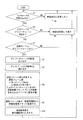
続いて、条件判断部21での判断処理および映像遅延処理部22での映像遅延処理について、図3および図4を用いて詳細に説明する。
Next, the determination process in the
制御部11内の条件判断部21は、最初に入力モードの切替があるか否かを判断し(S1)、切替があれば、ディスプレイ設定情報の入力モードから、デイジーチェーン出力可能な入力であるか否かを判断する(S2)。可能であるならば、次に、接続モードから、映像信号源との直接接続であるか、デイジーチェーン接続であるかの判断を行う(S3)。ここで、最初に入力モードの切替があるか否かを判断しているのは、ディスプレイが、デイジーチェーン接続可能な入力モードと、可能ではない入力モードを有している場合を想定しているためである。例えば、DVIモードはデイジーチェーン接続可能であるが、HDMIモードはデイジーチェーン接続ができない。そのため、入力モード切替時に映像遅延量の判断をすれば良いことになる。
The
入力モードの切替がない場合(S1でNO)、映像遅延の変更は必要ない(S4)。デイジーチェーン出力が可能でない場合(S2でNO)、もしくは映像信号源との直接接続である場合(S3でNO)、映像遅延処理は必要ないので、制御部11は入力された映像信号を遅延無しで表示させる(S5)。
When the input mode is not switched (NO in S1), it is not necessary to change the video delay (S4). If daisy chain output is not possible (NO in S2), or if it is a direct connection with a video signal source (NO in S3), the
また、デイジーチェーン接続されている場合は、デイジーチェーン台数とディスプレイのID番号とから条件判断部21が映像遅延時間を計算する。このため、制御部11は、記憶部18に格納されているディスプレイ設定情報からデイジーチェーン台数NとディスプレイのID番号nとを読み出す(S6,S7)。条件判断部21は、読み出されたデイジーチェーン台数NとディスプレイのID番号nとから、下記(1)式を用いて映像遅延時間を算出する。尚、ここでは映像遅延時間は遅延フレーム数として算出される。
In the case of daisy chain connection, the
F=|(N−n)×t/T| ・・・(1)
(1)式において、Fは遅延フレーム数、Tは1フレーム期間である。さらに、tは、デイジーチェーン1台分の遅延時間であり、ディスプレイの映像信号入出力デバイス(すなわち、映像入力部15および映像出力部16)における固有の値である。上述したように、10台デイジーチェーンする毎に1フレーム(16msec)分の映像遅延が発生すると仮定するならば、t=1.6msecである。
F = | (N−n) × t / T | (1)
In equation (1), F is the number of delay frames, and T is one frame period. Furthermore, t is a delay time for one daisy chain, and is a unique value in the video signal input / output device (that is, the
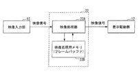
映像遅延処理部22は、条件判断部21で決定した映像遅延時間分の映像遅延処理を行う。このため、映像遅延処理部22は、図4に示すように、映像処理部22Aと映像処理用メモリ(フレームバッファ)22Bとを備えている。すなわち、映像遅延処理では、映像入力部15から入力される映像信号を、遅延フレーム数分の遅延が生じるように映像処理部22Aから映像処理用メモリ22Bに転送し(S9)、その後、遅延処理後の映像信号を表示駆動部12に出力する(S10)。尚、映像処理部22Aは、さらにIP変換やノイズ除去等の処理を行う。
The video
このように、本実施の形態に係るディスプレイでは、ディスプレイ側での設置状態に応じて、映像遅延量の調整を自動で行うことができる。このため、表示品位の改善と映像遅延の手動調整を行うための、人的コスト、追加の機材コストをかける必要が無い。 Thus, in the display according to the present embodiment, the video delay amount can be automatically adjusted according to the installation state on the display side. This eliminates the need for human costs and additional equipment costs for improving display quality and manually adjusting video delay.
尚、上記映像遅延処理にあたって、映像処理用メモリ22Bは遅延フレーム数分のメモリ容量を有することが必要である。すなわち、上記例では、1台目から10台目までのディスプレイにおいて最大2フレーム分の遅延を生じさせる必要があるため、映像処理用メモリ22Bとして2フレーム分のフレームバッファが必要となる。逆に言えば、上記マルチディスプレイ装置では、映像処理用メモリ22Bの容量、デイジーチェーン1台分の遅延時間t、映像信号における1フレーム期間によってデイジーチェーン接続が可能な最大接続台数が決まる。
In the video delay process, the
また、上記説明では、マルチディスプレイ装置を構成する各ディスプレイは基本的には同一の構成であるとしたが、映像処理用メモリ22Bの容量に関しては、接続順序によって異ならせても良い。すなわち、上記例では、2フレーム分の遅延を生じさせる1台目から10台目までのディスプレイでは映像処理用メモリ22Bの容量を2フレーム分とし、1フレーム分の遅延を生じさせる11台目から20台目までのディスプレイでは映像処理用メモリ22Bの容量を1フレーム分としても良い。さらに、遅延を生じさせない21台目から30台目までのディスプレイでは映像処理用メモリ22Bを省略することもできる。すなわち、複数のディスプレイをデイジーチェーン接続して構成されたマルチディスプレイにおいて、少なくとも一台が本発明のディスプレイである場合も含む。但し、製品としての供給を考えれば、各ディスプレイにおいて映像処理用メモリ22Bの容量は同一であることが好ましい。
In the above description, the displays constituting the multi-display device basically have the same configuration. However, the capacity of the
また、上記説明では、映像処理用メモリ22Bをフレームバッファとしたが、遅延時間が小さくければ、映像処理用メモリ22Bにラインバッファを用いた制御とすることも可能である。
In the above description, the
さらに、条件判断部21における遅延時間算出は、前述した(1)式に代えて下記(2)式を用いることも可能である。
Furthermore, the delay time calculation in the
F=|N×t/T|−|(n−1)×t/T| ・・・(2)
例えば、デイジーチェーン台数を25台、10台デイジーチェーンする毎に1フレーム分の映像遅延が発生すると仮定した場合、(1)式を用いて遅延時間を算出すると、ID番号が1〜5のディスプレイでは2フレーム分の遅延、ID番号が6〜15のディスプレイでは1フレーム分の遅延、ID番号が16〜25のディスプレイでは遅延無しとなる。一方、(2)式を用いて遅延時間を算出すると、ID番号が1〜10のディスプレイでは2フレーム分の遅延、ID番号が11〜20のディスプレイでは1フレーム分の遅延、ID番号が21〜25のディスプレイでは遅延無しとなる。このように、どちらの算出式を用いても、それぞれのディスプレイの映像遅延量は1フレーム以内の範囲に調整できる。
F = | N × t / T | − | (n−1) × t / T | (2)
For example, assuming that the number of daisy chains is 25 and that 10 frames are delayed every 10 daisy chains, the delay time is calculated using equation (1), and the
本発明は上述した実施形態に限定されるものではなく、請求項に示した範囲で種々の変更が可能であり、異なる実施形態にそれぞれ開示された技術的手段を適宜組み合わせて得られる実施形態についても本発明の技術的範囲に含まれる。 The present invention is not limited to the above-described embodiments, and various modifications can be made within the scope shown in the claims, and embodiments obtained by appropriately combining technical means disclosed in different embodiments. Is also included in the technical scope of the present invention.
本発明は、デイジーチェーン接続された複数のディスプレイにおける映像信号ズレを抑制でき、複数のディスプレイを接続してなるマルチディスプレイ装置に利用することができる。 INDUSTRIAL APPLICABILITY The present invention can suppress a video signal shift in a plurality of displays connected in a daisy chain, and can be used for a multi-display apparatus in which a plurality of displays are connected.
10 ディスプレイ
11 制御部
12 表示駆動部
13 表示部
14 通信部
15 映像入力部
16 映像出力部
17 操作入力部
18 記憶部(記憶手段)
21 条件判断部(条件判断手段)
22 映像遅延処理部(映像遅延手段)
22A 映像処理部
22B 映像処理用メモリ
30 映像出力機器
31 制御端末
DESCRIPTION OF
21 Condition Judgment Unit (Condition Judgment Unit)
22 Video delay processor (video delay means)
22A
Claims (5)
デイジーチェーン接続されているディスプレイの接続台数と、デイジーチェーン接続における自機の接続順序とを記憶する記憶手段と、
上記接続順序と上記接続台数とに基づき、自機における映像遅延時間を算出する条件判断手段と、
上記条件判断手段によって算出された上記映像遅延時間分、表示前の映像信号を遅延させる映像遅延手段とを備えていることを特徴とするディスプレイ。 In a display that can constitute a multi-display device by being daisy chain connected,
Storage means for storing the number of connected daisy chained displays and the connection order of the own device in the daisy chain connection;
Based on the connection order and the number of connected devices, a condition determining means for calculating video delay time in the own device,
A display comprising: video delay means for delaying a video signal before display by the video delay time calculated by the condition judging means.
上記映像処理用メモリは、フレームバッファであることを特徴とする請求項2に記載のディスプレイ。 The condition determining means calculates the video delay time as the number of delay frames,
The display according to claim 2, wherein the video processing memory is a frame buffer.
上記複数のディスプレイのうちの少なくとも一台は、上記請求項1から3の何れか一項に記載のディスプレイであることを特徴とするマルチディスプレイ装置。 It consists of multiple displays connected in a daisy chain,
4. The multi-display apparatus according to claim 1, wherein at least one of the plurality of displays is the display according to claim 1.
Priority Applications (1)
| Application Number | Priority Date | Filing Date | Title |
|---|---|---|---|
| JP2010288810A JP2012138712A (en) | 2010-12-24 | 2010-12-24 | Display and multi-display device |
Applications Claiming Priority (1)
| Application Number | Priority Date | Filing Date | Title |
|---|---|---|---|
| JP2010288810A JP2012138712A (en) | 2010-12-24 | 2010-12-24 | Display and multi-display device |
Publications (1)
| Publication Number | Publication Date |
|---|---|
| JP2012138712A true JP2012138712A (en) | 2012-07-19 |
Family
ID=46675803
Family Applications (1)
| Application Number | Title | Priority Date | Filing Date |
|---|---|---|---|
| JP2010288810A Pending JP2012138712A (en) | 2010-12-24 | 2010-12-24 | Display and multi-display device |
Country Status (1)
| Country | Link |
|---|---|
| JP (1) | JP2012138712A (en) |
Cited By (9)
| Publication number | Priority date | Publication date | Assignee | Title |
|---|---|---|---|---|
| WO2014174630A1 (en) * | 2013-04-25 | 2014-10-30 | Necディスプレイソリューションズ株式会社 | Multi-monitor and display method for multi-monitor |
| JP2015064718A (en) * | 2013-09-25 | 2015-04-09 | アンリツ株式会社 | Signal processor, signal analysis system, signal generation system, signal analysis method, and signal generation method |
| JP2016225744A (en) * | 2015-05-28 | 2016-12-28 | 株式会社リコー | Radio communication system and method |
| JP2017063392A (en) * | 2015-09-25 | 2017-03-30 | ブラザー工業株式会社 | Video processing device and video processing system |
| KR101724430B1 (en) * | 2016-09-20 | 2017-04-10 | (주)베이직테크 | Synchronization apparatus and method for led imaging apparatus |
| WO2017130353A1 (en) * | 2016-01-28 | 2017-08-03 | Necディスプレイソリューションズ株式会社 | Multi-display device and method for controlling multi-display device |
| WO2022004449A1 (en) * | 2020-07-03 | 2022-01-06 | ソニーグループ株式会社 | Transmission system, transmission method, and transmission device |
| US11221815B2 (en) | 2015-02-25 | 2022-01-11 | Sharp Nec Display Solutions, Ltd. | Display system, display device, and display method |
| WO2022208221A1 (en) * | 2021-03-31 | 2022-10-06 | 株式会社半導体エネルギー研究所 | Display apparatus, electronic equipment, and method for producing semiconductor device |
-
2010
- 2010-12-24 JP JP2010288810A patent/JP2012138712A/en active Pending
Cited By (14)
| Publication number | Priority date | Publication date | Assignee | Title |
|---|---|---|---|---|
| WO2014174630A1 (en) * | 2013-04-25 | 2014-10-30 | Necディスプレイソリューションズ株式会社 | Multi-monitor and display method for multi-monitor |
| US10073667B2 (en) | 2013-04-25 | 2018-09-11 | Nec Display Solutions, Ltd. | Multi-monitor and display method for multi-monitor |
| JP2015064718A (en) * | 2013-09-25 | 2015-04-09 | アンリツ株式会社 | Signal processor, signal analysis system, signal generation system, signal analysis method, and signal generation method |
| US11221815B2 (en) | 2015-02-25 | 2022-01-11 | Sharp Nec Display Solutions, Ltd. | Display system, display device, and display method |
| JP2016225744A (en) * | 2015-05-28 | 2016-12-28 | 株式会社リコー | Radio communication system and method |
| JP2017063392A (en) * | 2015-09-25 | 2017-03-30 | ブラザー工業株式会社 | Video processing device and video processing system |
| JPWO2017130353A1 (en) * | 2016-01-28 | 2018-07-19 | Necディスプレイソリューションズ株式会社 | Multi-display apparatus and control method for multi-display apparatus |
| CN108496218A (en) * | 2016-01-28 | 2018-09-04 | Nec显示器解决方案株式会社 | Multi-display apparatus and method for controlling multi-display apparatus |
| WO2017130353A1 (en) * | 2016-01-28 | 2017-08-03 | Necディスプレイソリューションズ株式会社 | Multi-display device and method for controlling multi-display device |
| CN108496218B (en) * | 2016-01-28 | 2021-10-29 | 夏普Nec显示器解决方案株式会社 | Multi-display device and method for controlling the same |
| EP3410426B1 (en) * | 2016-01-28 | 2023-09-06 | Sharp NEC Display Solutions, Ltd. | Multi-display device and method for controlling multi-display device |
| KR101724430B1 (en) * | 2016-09-20 | 2017-04-10 | (주)베이직테크 | Synchronization apparatus and method for led imaging apparatus |
| WO2022004449A1 (en) * | 2020-07-03 | 2022-01-06 | ソニーグループ株式会社 | Transmission system, transmission method, and transmission device |
| WO2022208221A1 (en) * | 2021-03-31 | 2022-10-06 | 株式会社半導体エネルギー研究所 | Display apparatus, electronic equipment, and method for producing semiconductor device |
Similar Documents
| Publication | Publication Date | Title |
|---|---|---|
| JP2012138712A (en) | Display and multi-display device | |
| TWI493521B (en) | Display driver integrated circuits, and systems and methods using display driver integrated circuits | |
| US20100315427A1 (en) | Multiple graphics processing unit display synchronization system and method | |
| KR102293145B1 (en) | Display driving device including source driver and timing controller and operating method of display driving device | |
| JP2009531979A5 (en) | ||
| WO2010078448A3 (en) | Seamlessly displaying migration of several video images | |
| US9286851B2 (en) | Display panel driving device and driving method for saving electrical energy thereof | |
| CN202275592U (en) | System for controlling over driver (OD) of liquid crystal display (LCD) | |
| JP2010256810A5 (en) | ||
| US9019249B2 (en) | Display panel driving device and driving method thereof for saving electrical energy | |
| TW202203198A (en) | Scalar, display device and associated data processing method | |
| KR20090106070A (en) | System and method for setting display unit of monitor | |
| TWI483237B (en) | System,method and computer program product for displaying a video signal | |
| KR20130093432A (en) | Driving device, display device including the same and driving method thereof | |
| JP5968011B2 (en) | Image processing apparatus and control method thereof | |
| WO2016135881A1 (en) | Display system, display method, and display program | |
| JP2007156462A5 (en) | ||
| CN101989400B (en) | Frame rate-scalable image processing system and method | |
| KR100738497B1 (en) | System of outputing multi-sync video | |
| JP2005234566A (en) | Display system and image processor | |
| US9697794B2 (en) | Display system | |
| JP2002221952A (en) | Image data transmission method, and image display system and display device using the same | |
| TWI600003B (en) | Display processor and timing controller with dithering | |
| KR100689591B1 (en) | Timing controller and timing control method | |
| JP4176605B2 (en) | Display signal converter |