JP2012115531A - Electronic endoscope and electronic endoscope system - Google Patents
Electronic endoscope and electronic endoscope system Download PDFInfo
- Publication number
- JP2012115531A JP2012115531A JP2010268893A JP2010268893A JP2012115531A JP 2012115531 A JP2012115531 A JP 2012115531A JP 2010268893 A JP2010268893 A JP 2010268893A JP 2010268893 A JP2010268893 A JP 2010268893A JP 2012115531 A JP2012115531 A JP 2012115531A
- Authority
- JP
- Japan
- Prior art keywords
- electronic endoscope
- signal
- band correction
- unit
- hold circuit
- Prior art date
- Legal status (The legal status is an assumption and is not a legal conclusion. Google has not performed a legal analysis and makes no representation as to the accuracy of the status listed.)
- Withdrawn
Links
Images


Landscapes
- Closed-Circuit Television Systems (AREA)
- Instruments For Viewing The Inside Of Hollow Bodies (AREA)
- Endoscopes (AREA)
Abstract
Description
本発明は、電子内視鏡及び電子内視鏡システムに関し、より詳しくは、伝送ケーブルによる信号伝送に伴う信号の劣化を防止することが可能な電子内視鏡及び電子内視鏡システムに関する。 The present invention relates to an electronic endoscope and an electronic endoscope system, and more particularly, to an electronic endoscope and an electronic endoscope system that can prevent signal deterioration associated with signal transmission using a transmission cable.
従来より、先端部に備えられたCCD(Charge Coupled Device)やCMOS(Complementary Metal-Oxide Semiconductor)などの撮像素子によって観察対象の撮影を行う電子内視鏡と、観察対象を照明するための光を電子内視鏡に供給するとともに、電子内視鏡により撮像された画像を処理してモニタに出力するビデオプロセッサとからなる電子内視鏡システムが知られている。このような電子内視鏡システムは、体腔内の部位の観察や治療を行うための医療分野や、部品の観察又は検査を行うための工業分野において広く実用に供されている。 Conventionally, an electronic endoscope that takes an image of an observation target with an imaging element such as a charge coupled device (CCD) or a complementary metal-oxide semiconductor (CMOS) provided at the tip, and light for illuminating the observation target There is known an electronic endoscope system that includes a video processor that supplies an electronic endoscope and processes an image captured by the electronic endoscope and outputs the processed image to a monitor. Such an electronic endoscope system is widely put into practical use in the medical field for observing and treating a site in a body cavity and in the industrial field for observing or inspecting a part.
このような電子内視鏡システムとして、特許文献1に開示されるものが知られている。特許文献1では、電子内視鏡の先端部に設けられたCCDから出力される信号が、同軸ケーブルにより制御部に伝送される。伝送された信号は、制御部のAFE(Analog Front End)において相関二重サンプリング処理や信号増幅処理が施された後、デジタル信号に変換されて信号処理部に送られる。そして、信号処理部において、ホワイトバランス、ガンマ補正などの映像処理や、フォーマット処理、圧縮処理などのエンコード処理が行われ、生成された画像がモニタなどに表示される。
As such an electronic endoscope system, one disclosed in
最近では電子内視鏡システムにおいて画像の高精細化が求められており、撮像素子を高画素化しつつある。撮像素子の各画素の輝度データは、撮像素子に入力する駆動パルスに基づいて出力されるため、撮像素子を高画素化する場合には、駆動パルスの周波数を高める必要が生じる。しかし、駆動パルスの周波数を高めた場合、駆動パルスの伝送手段たるケーブルによって信号の劣化が生じるため、正確な駆動パルスを供給することが難しくなるという問題がある。そこで、従来は、複数チャンネルによる出力を行う撮像素子を用いて並列に信号を読み出すことで、駆動パルスの周波数を高めることなく画像の高精細化を図ろうとしていた。しかし、撮像素子が複数チャンネル出力を有していると、出力信号を伝送するケーブルがチャンネル数だけ必要となり、素線を増やさなければならない。この結果、ケーブル径が太くなり、電子内視鏡の挿入部の細径化を図ることができないといった問題がある。挿入部の細径化は、患者の体腔内への挿入時に、患者に与える負担を低減する上で欠かせない。 In recent years, there has been a demand for high-definition images in electronic endoscope systems, and the number of pixels in an image sensor is increasing. Since the luminance data of each pixel of the image sensor is output based on the drive pulse input to the image sensor, it is necessary to increase the frequency of the drive pulse when the pixel of the image sensor is increased. However, when the frequency of the drive pulse is increased, there is a problem that it is difficult to supply an accurate drive pulse because the signal is deteriorated by the cable serving as the drive pulse transmission means. Therefore, conventionally, it has been attempted to increase the definition of an image without increasing the frequency of the drive pulse by reading out signals in parallel using an imaging device that performs output using a plurality of channels. However, if the imaging device has a plurality of channel outputs, cables for transmitting output signals are required for the number of channels, and the number of wires must be increased. As a result, there is a problem that the cable diameter becomes thick and the insertion portion of the electronic endoscope cannot be reduced in diameter. The reduction in the diameter of the insertion portion is indispensable for reducing the burden on the patient when inserted into the body cavity of the patient.
また、上記のような従来の電子内視鏡システムにおいては、伝送ケーブルが電子内視鏡の先端部から基端部に延在する長尺のケーブルであるため、空中伝搬するノイズを拾い易く、CCDからの出力信号を伝送する際に伝送ケーブルによる信号の劣化が大きく影響しかねない。 Further, in the conventional electronic endoscope system as described above, since the transmission cable is a long cable extending from the distal end portion of the electronic endoscope to the proximal end portion, it is easy to pick up noise that propagates in the air, When the output signal from the CCD is transmitted, the signal deterioration due to the transmission cable can have a great influence.
CCDが設けられている内視鏡先端部にA/D変換器を設け、CCDから出力されるアナログ信号をA/D変換によりデジタル信号に変換して伝送ケーブルにより伝送する場合、A/D変換によって変換されたデジタル信号をシリアル信号へ変換し、制御部へ出力することにより、電子内視鏡の先端部にて画像信号および出力信号をデジタル信号へと変換した上で制御部へ伝送することができ、直接アナログ信号を伝送させる場合に比べ、伝送による画像信号の劣化を低減することが可能となる。しかし、A/D変換におけるビット数が大きくなるにつれて伝送ケーブルにおける信号の伝送速度をより高速にする必要がある。シリアル伝送では信号のベースクロックが高周波になるため、伝送ケーブルにおいて波形歪みが発生したり、信号に高周波ノイズが生じたりする。したがって、電子内視鏡内においてEMC(Electromagnetic Compatibility)を達成する上での制約が生じて良好な電磁波干渉の対策を採ることができなかったり、伝送ケーブルの周波数制限を考慮しなければならかったりするなどの不都合が生じる可能性がある。 When an A / D converter is installed at the distal end of the endoscope where the CCD is provided and the analog signal output from the CCD is converted into a digital signal by A / D conversion and transmitted through a transmission cable, A / D conversion By converting the digital signal converted by the above into a serial signal and outputting it to the control unit, the image signal and the output signal are converted into a digital signal at the tip of the electronic endoscope and then transmitted to the control unit Therefore, it is possible to reduce the deterioration of the image signal due to the transmission as compared with the case where the analog signal is directly transmitted. However, as the number of bits in A / D conversion increases, it is necessary to increase the signal transmission speed in the transmission cable. In serial transmission, the signal base clock has a high frequency, so that waveform distortion occurs in the transmission cable and high-frequency noise occurs in the signal. Accordingly, there are restrictions in achieving EMC (Electromagnetic Compatibility) in the electronic endoscope, and it is not possible to take a good countermeasure against electromagnetic interference, or it is necessary to consider the frequency limitation of the transmission cable. Inconvenience such as doing may occur.
本発明は上記の事情に鑑みてなされたものである。本発明の目的は、低周波伝送のシリアル伝送により画像信号を伝送しつつ画像信号の劣化を防止し、さらに内視鏡先端の太径化を防止することが可能な電子内視鏡及び電子内視鏡システムを提供することである。 The present invention has been made in view of the above circumstances. An object of the present invention is to provide an electronic endoscope and an electronic endoscope capable of preventing deterioration of the image signal while transmitting the image signal by low-frequency serial transmission and further preventing the diameter of the endoscope from becoming thicker. An endoscope system is provided.
上記の課題を解決する本発明の一実施形態による電子内視鏡は、撮像素子と、撮像素子からの信号をサンプルホールドするサンプルホールド回路と、サンプルホールド回路からの信号を伝送するシリアルケーブルと、シリアルケーブルにより伝送された信号に対して帯域補正処理を行う帯域補正部とを有する。これにより、電子内視鏡において画像信号の伝送をシリアル伝送により行うことができるため、撮像素子が高画素化した場合にもケーブル本数を増やす必要がなく、波形歪みや高周波ノイズが発生しない信号伝送が実現する。したがって、電子内視鏡が太径化しない。また、サンプルホールド回路によってサンプルホールド処理された信号を伝送するため、高周波伝送を行う必要がなくなる。さらに、サンプルホールド処理を行った信号に対して帯域補正を行うため、帯域補正時に複雑な信号を処理する必要がない。そして、サンプルホールド処理後の信号変化は緩やかであるため、比較的高速度かつ低ノイズのA/D変換器を用いてA/D変換を行うことも可能になる。また、サンプルホールド回路を電子内視鏡の先端部に設け、帯域補正部を電子内視鏡の基部に設けた構成や、サンプルホールド回路を先端部の代わりに電子内視鏡の操作部に設けた構成としてもよい。 An electronic endoscope according to an embodiment of the present invention that solves the above problems includes an imaging device, a sample-and-hold circuit that samples and holds a signal from the imaging device, a serial cable that transmits a signal from the sample-and-hold circuit, A band correction unit that performs band correction processing on a signal transmitted through the serial cable. As a result, image signals can be transmitted serially in an electronic endoscope, so there is no need to increase the number of cables even when the number of pixels of the image sensor is increased, and signal transmission that does not cause waveform distortion or high-frequency noise. Is realized. Therefore, the diameter of the electronic endoscope is not increased. Further, since the signal sampled and held by the sample and hold circuit is transmitted, it is not necessary to perform high frequency transmission. Further, since band correction is performed on the signal that has been subjected to the sample hold process, it is not necessary to process a complicated signal during band correction. Since the signal change after the sample and hold process is gentle, it is possible to perform A / D conversion using a relatively high speed and low noise A / D converter. In addition, a sample hold circuit is provided at the tip of the electronic endoscope, a band correction unit is provided at the base of the electronic endoscope, and a sample hold circuit is provided at the operation part of the electronic endoscope instead of the tip. It is good also as a structure.
さらに、帯域補正部は、シリアルケーブルにより伝送された信号を増幅する増幅回路を有し、増幅回路は、可変抵抗を有し、電子内視鏡は、さらにシリアルケーブルのケーブル長に応じて可変抵抗の抵抗値を変更する抵抗値制御手段を有する。また、電子内視鏡は、帯域補正部から出力される信号に基づいて生成された画像のノイズ量を測定するノイズ計測部を有し、抵抗値制御手段は、さらにノイズ計測部により測定されるノイズ量に基づいて可変抵抗の抵抗値を調整する。 Further, the band correction unit has an amplifier circuit that amplifies the signal transmitted by the serial cable, the amplifier circuit has a variable resistor, and the electronic endoscope further has a variable resistor according to the cable length of the serial cable. Resistance value control means for changing the resistance value of the. The electronic endoscope further includes a noise measuring unit that measures the amount of noise in the image generated based on the signal output from the band correction unit, and the resistance value control unit is further measured by the noise measuring unit. The resistance value of the variable resistor is adjusted based on the amount of noise.
また、本発明の一実施形態による電子内視鏡システムは、撮像素子と、撮像素子からの信号をサンプルホールドするサンプルホールド回路と、サンプルホールド回路からの信号を伝送するシリアルケーブルとを有する電子内視鏡と、シリアルケーブルにより伝送された信号に対して帯域補正処理を行う帯域補正部を有するビデオプロセッサとを有する。すなわち、本発明においては、帯域補正部を電子内視鏡ではなく、電子内視鏡と接続されるビデオプロセッサに設けた構成としてもよい。さらに、サンプルホールド回路を電子内視鏡の先端部に設けた構成や、サンプルホールド回路を先端部の代わりに電子内視鏡の操作部に設けた構成としてもよい。 An electronic endoscope system according to an embodiment of the present invention includes an image pickup device, a sample hold circuit that samples and holds a signal from the image pickup device, and a serial cable that transmits a signal from the sample hold circuit. And a video processor having a band correction unit that performs band correction processing on a signal transmitted through a serial cable. That is, in the present invention, the band correction unit may be provided in a video processor connected to the electronic endoscope instead of the electronic endoscope. Furthermore, a configuration in which the sample hold circuit is provided at the distal end portion of the electronic endoscope or a configuration in which the sample hold circuit is provided in the operation portion of the electronic endoscope instead of the distal end portion may be employed.
本発明の電子内視鏡及び電子内視鏡システムによれば、低周波伝送のシリアル伝送により画像信号を伝送しつつ画像信号の劣化を防止し、さらに内視鏡先端の細径化を図ることができる。 According to the electronic endoscope and the electronic endoscope system of the present invention, it is possible to prevent the image signal from being deteriorated while transmitting the image signal by low-frequency serial transmission, and to further reduce the diameter of the endoscope tip. Can do.
以下、図面を参照して、本発明の一実施形態における電子内視鏡システムについて説明する。 Hereinafter, an electronic endoscope system according to an embodiment of the present invention will be described with reference to the drawings.
図1は、本発明の実施形態における電子内視鏡システム1の概略を示すブロック図である。本実施形態の電子内視鏡システム1は、患者の体腔内における観察や処置を行うための医療用の電子内視鏡システムである。本実施形態の電子内視鏡システム1は、電子内視鏡10、ビデオプロセッサ20及びモニタ30を備えている。
FIG. 1 is a block diagram showing an outline of an
電子内視鏡10は、患者の体内に挿入される挿入部110と、電子内視鏡10やビデオプロセッサ20における種々の処理を実行するスイッチなどが設けられている操作部120と、ビデオプロセッサ20に電気的および光学的に接続される接続部130を有する。電子内視鏡10の接続部130から挿入部110までは、ビデオプロセッサ20から供給される照明光を伝搬するためのライトガイド111が延在している。また、挿入部110には、ライトガイド111によって伝搬された照明光を観察部位に出射するための配光レンズ112、観察部位で反射された照明光を撮像素子の受光面に結像させるための対物レンズ113、受光面に結像された被写体像に基づいてアナログ画像信号を生成する撮像素子であるCCD114が配置されている。
The
また、電子内視鏡10は、電子内視鏡10に内蔵される各構成要素(例えば、タイミングジェネレータ136、帯域補正部135、前段処理部132)を統括的に制御するCPU133及び後述する帯域補正部135に内蔵されるデジタルポテンショメータ338〜341の抵抗値のデータを記憶するメモリ150を有している。CPU133は、ビデオプロセッサ20に内蔵されるシステムコントローラ201に接続されており、システムコントローラ201からの指示に従って電子内視鏡10に内蔵される各構成要素を制御する。
In addition, the
ビデオプロセッサ20は、電子内視鏡システム1を統括的に制御するシステムコントローラ201を有している。術者によってビデオプロセッサ20の電源が投入されると、システムコントローラ201は、不図示のメモリからプログラムを読出し、光源202を点灯して撮像動作を開始する。光源202は、キセノンランプやハロゲンランプなどの高輝度ランプにより構成される。そして、光源202から出射された光は、集光レンズ203を介して電子内視鏡10に設けられたライトガイド111の入射端に進行する。ライトガイド111の入射端に進行した光は、接続部130及び操作部120を経由して挿入部110の先端に配置される配光レンズ112から、体内の観察部位に出射される。そして、出射された光が観察部位によって反射され、対物レンズ113を介してCCD114の受光面に結像される。
The
本実施形態では、カラー撮像方式として単板同時式が採用されており、CCD114の受光面上にはイエロー(Ye)、シアン(Cy)、マゼンタ(Mg)、グリーン(G)の各色要素が市松状に並べられた補色カラーフィルタ(図示せず)が受光面の各画素に対応して配置されている。そして、CCD114では、補色カラーフィルタを透過した光の強度に応じた画像信号が光電変換により発生し、所定時間間隔ごとに1フレーム分の画像信号が、色差線順次方式によって順次読み出される。本実施形態では、インターライントランスファ方式のCCDが使用されており、NTSC方式の垂直同期周波数に対応して、例えば約1/30秒間隔ごとに1フレーム分のアナログ画像信号が順次読み出されて出力される。なお、撮像素子として、上記補色CCDではなく、原色(R,G,B)のカラーフィルタを備える原色CCDやCMOSなどを用いることも可能である。また、いわゆるモノクロ面順次方式を採用することも可能である。
In this embodiment, a single plate simultaneous type is adopted as a color imaging method, and yellow (Ye), cyan (Cy), magenta (Mg), and green (G) color elements are on a checkered pattern on the light receiving surface of the
タイミングジェネレータ136は、遅延時間補正回路136aを有する。遅延時間補正回路136aは、シリアルケーブル140のケーブル長に応じて発生する信号の伝送遅延を補正する回路であり、例えば、複数のディレイラインで構成される。タイミングジェネレータ136は、遅延時間補正回路136aによって各信号のタイミングを調整し、電子内視鏡10内の各ブロックの動作を制御する。なお、便宜上、タイミングジェネレータ136とタイミングジェネレータ136によって制御される接続部130内の各処理ブロックとを接続する結線は図示を省略している。タイミングジェネレータ136は、シリアルケーブル140による信号の伝送遅延分の位相を遅らせた同期信号(SHPパルス及びSHDパルス)を生成する。CCDドライバ(図示せず)は、タイミングジェネレータ136からの同期信号に基づいて駆動パルスを生成し、この駆動パルスをCCD114に供給する。CCD114は、駆動パルスに基づいて駆動され、撮像した被写体のアナログ画像信号を生成する。
The
CCD114にて生成されるアナログ画像信号は、サンプルホールド回路として相関二重サンプリング処理を行うCDS(Correlated Double Sampling)115に送られる。CDS115では、タイミングジェネレータ136から出力されるクランプパルスにより、CCD114からのアナログ画像信号のフィードスルー期間と映像信号出力期間の出力がクランプされる。
The analog image signal generated by the
CDS115では、さらに出力の信号レベルがサンプルホールドされ、アンプ雑音やリセット雑音が除去された信号がバッファ116に送られる。CCD114からのアナログ画像信号は、CDS115及びバッファ116を介して、シリアルケーブル140により操作部120を経由して接続部130に送られる。
In the
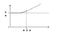
挿入部110からシリアルケーブル140により接続部130に送られたアナログ画像信号は、帯域補正部135に送られる。ここで本実施形態における帯域補正について図2のグラフを参照しながら説明する。図2は、本実施形態のシリアルケーブル140の周波数特性を示すグラフであり、縦軸はシリアルケーブル140の利得(すなわち、入力側電圧Vinに対する出力側電圧Voutの比(Vout/Vin)を表し、横軸はシリアルケーブル140で伝送される信号の周波数を表している。
The analog image signal sent from the
図2に示されるように、ある特定のケーブル長を有するシリアルケーブル140は、抵抗、インダクタンス及びキャパシタンス成分を有するため周波数特性を有する。そして、この周波数特性は、伝送する信号の周波数が高くなればなるほど利得が減衰する特性を示し、一般的には、なだらかな右下がりのカーブとなる。したがって、シリアルケーブル140によって伝送する信号の周波数が高い場合には、シリアルケーブル140の出力側で減衰した信号の補正を行わないとシリアルケーブル140に入力された信号が再現できないこととなる。ここで、CCD114から出力されるアナログ画像信号は、フィードスルー期間の出力信号と映像信号出力期間の出力信号とを含んでおり、低周波から高周波に亘る広い周波数帯域の信号となる。このため、このアナログ画像信号をシリアルケーブル140で伝送し、出力側で再現しようとする場合には、低周波から高周波に亘る広い周波数帯域で減衰した信号の補正を行う必要が生じる。そこで、本実施形態の電子内視鏡10では、CCD114から出力されるアナログ画像信号を一旦CDS115によってサンプルホールドし、サンプルホールドされた伝送信号をシリアルケーブル140で伝送する構成としている。すなわち、CDS115によって画像再生に必要な信号(すなわち、アナログ画像信号のフィードスルー期間と映像信号出力期間の出力)をサンプルし、一定期間ホールドすることにより、アナログ画像信号に含まれる高周波の成分を低周波の成分に変換し、後段のA/D変換部134で要求される信号のみシリアルケーブル140によって伝送している。このような構成により、シリアルケーブル140によって伝送される信号は、低周波の帯域のみシリアルケーブル140の出力側で補正をすれば再現できるため、アナログ画像信号を直接伝送した場合と比較して補正が容易となる。また、図2に示すように、低周波の帯域は、高周波の帯域に比較して利得の減衰が少なく、少ない補正量で補正できるため、S/N比の良い信号を得ることができる。以上のように、本実施形態の電子内視鏡10では、アナログ画像信号をCDS115によってサンプルホールドし、サンプルホールドされた伝送信号をシリアルケーブル140で伝送する構成とするため、CDS115を挿入部110の先端部に配置し、伝送信号の補正を行う帯域補正部135を接続部130に配置している。
As shown in FIG. 2, the
帯域補正部135は、シリアルケーブル140によって伝送される伝送信号を逆補正フィルタを用いて補正する。図3は、本実施形態の帯域補正部135の逆補正フィルタの特性を示すグラフである。図3の縦軸は、帯域補正部135の利得(すなわち、入力側電圧Vinに対する出力側電圧Voutの比(Vout/Vin)を表し、横軸は帯域補正部135で補正する信号の周波数を表している。図3に示すように、帯域補正部135は、図2に示すシリアルケーブル140の利得の減衰分を補うように補正を行い、後段のA/D変換部134で要求される信号を再現するために必要な周波数foまでの帯域(すなわち、低周波の帯域)において、フラットな(利得が1となるような)特性が得られるように構成される。すなわち、本実施形態においては、後段のA/D変換部134で不要な高周波の成分(図3中点線で示す周波数foよりも高い周波数)対しては補正を行う必要がなく、これら補正を行う必要のない帯域の信号に対しては、例えば帯域補正部135による処理の後にLPF(Low-pass Filter)(図示せず)によって信号の高周波成分をカットする処理を施すことができる。以上のように、本実施形態の帯域補正部135によれば、後段のA/D変換部134で要求される、アナログ画像信号のフィードスルー期間の出力信号と映像信号出力期間の出力信号に対してケーブル特性に応じて適切な帯域補正を行いつつ、帯域補正処理を簡略化することができる。
The
帯域補正部135により帯域補正が施された信号は、A/D変換部134に送られてデジタル信号に変換される。A/D変換部134は、タイミングジェネレータ136から供給されるクロックパルスに応じた所定のサンプリング周波数及び所定のビット数でアナログ信号のサンプリング及び量子化を行う。A/D変換部134によりデジタル信号に変換された画像信号は、前段処理部132に送られる。前段処理部132は、入力される画像信号を輝度信号Y及び色差信号Cb,Crからなる画像信号に変換する。そして、変換した輝度信号Y及び色差信号Cb,Crをそれぞれ増幅した後、マトリクス回路(図示せず)に送り、CCD114のフィルタ特性に応じて、変換特性を決定するマトリクス係数の値を変更し、画像信号の色補正を行う。マトリクス回路は、入力される輝度信号Y及び色差信号Cb,Crを混色のない3原色信号R,G,Bに変換して出力する。マトリクス回路によって変換されたR,G,Bの各画像信号は、それぞれ増幅されて適切な信号レベルに調整された後に、各色ごとに画像メモリ(図示せず)に格納される。
The signal subjected to the band correction by the
画像メモリから読み出された画像信号は、D/A変換部131によってアナログ信号に変換された後、ビデオプロセッサ20の後段処理部204に送られる。後段処理部204は、画像メモリから送られてきた画像信号をデジタルビデオ信号やRGBビデオ信号、コンポジットビデオ信号、Y/C信号等に変換した後、観察画像としてモニタ30に出力する。術者は、モニタ30に表示される観察画像を確認しながら体腔内の部位の観察や治療を行う。
The image signal read from the image memory is converted to an analog signal by the D /
図4は、本実施形態の電子内視鏡システム1に内蔵される帯域補正部135の回路図である。図3に示すように、帯域補正部135は、オペアンプ(OP)336、337と可変抵抗であるデジタルポテンショメータ(DPM)338〜341を有する。また、メモリ150(図1)には、シリアルケーブル140のケーブル長に応じて定まる周波数特性に基づいて適切な帯域補正を行えるように、あらかじめ決定された各デジタルポテンショメータの設定値が格納されている。すなわち、本実施形態においては、図2に示されるシリアルケーブル140の周波数特性に応じてデジタルポテンショメータ338〜341の抵抗値が決定され、メモリ150に各抵抗値のデータが格納されている。電子内視鏡システム1の起動時に、CPU133は、抵抗値制御手段として、メモリ150から上記の各抵抗値のデータを読み出して、デジタルポテンショメータ338〜341の抵抗値をそれぞれ設定する。したがって、帯域補正部135において、シリアルケーブルの長さに合わせたフィルタ特性を設定して帯域補正を実行することができる。
FIG. 4 is a circuit diagram of the
そして、上述のように、帯域補正部135によって帯域補正が行われた信号は、A/D変換部134に送られデジタル信号に変換された後、前段処理部132に送られる(図1)。
As described above, the signal whose band has been corrected by the
以上が本発明の実施形態の説明である。しかし、本発明は、上記の構成に限定されるものではなく、本発明の技術的思想の範囲において様々な変形が可能である。例えば、本実施形態では、図2に示されるシリアルケーブル140の周波数特性に応じて予め決定されたデジタルポテンショメータ338〜341の抵抗値を用いて帯域補正を行う構成としたが、画像に含まれるノイズ量に基づいてデジタルポテンショメータ338〜341の抵抗値をフィードバック制御する構成とすることも可能である。
The above is the description of the embodiment of the present invention. However, the present invention is not limited to the above-described configuration, and various modifications can be made within the scope of the technical idea of the present invention. For example, in the present embodiment, the band correction is performed using the resistance values of the
図5は、図1に示される本発明の一実施形態における電子内視鏡システムの変形例を示すブロック図である。本変形例は、図1に示される本発明の一実施形態の前段処理部132にノイズ計測部132aを追加したものである。図5においては、上述の実施の形態と異なる部分のみを説明するため、電子内視鏡10に内蔵されている帯域補正部135、A/D変換部134、前段処理部132M、CPU133、メモリ150のみ示している。なお、図5において、上述の実施形態と共通する構成については、図1及び図4と同一の符号を付している。
FIG. 5 is a block diagram showing a modification of the electronic endoscope system shown in FIG. 1 according to the embodiment of the present invention. In this modification, a
図5に示されるように、本変形例の前段処理部132Mは、ノイズ計測部132aを有している。ノイズ計測部132aは画像に発生しているノイズに関するデータを取得する。CPU133は、ノイズ計測部132aから得られるノイズの計測結果に基づいて、電子内視鏡システムにおけるホワイトバランス調整時に最も白い領域におけるノイズ(分散や偏差など)が最小となるように、デジタルポテンショメータ338〜341の抵抗値を調節するように構成されている。ホワイトバランス調整時のノイズは、帯域補正部135による帯域補正が適正に行われていないことを示している(すなわち、帯域補正部135のフィルタ特性が最適でないことを示している)ため、生成された画像に含まれるノイズ量に基づいてデジタルポテンショメータ338〜341の抵抗値をフィードバック制御することにより、リアルタイムかつより高精度の帯域補正を実行することができる。
As shown in FIG. 5, the
なお、上記の説明では、CDS115は電子内視鏡10の挿入部110に設けられているが、CDS115を操作部120に設けてもよい。この場合、タイミングジェネレータ136とCDS115を接続する信号線を短縮することができるため、挿入部110の細径化を期待することができる。また、CDS115の代わりにサンプルホールドアンプを用いても本発明の効果を得ることができる。また、帯域補正部135以降の各処理ブロックは、ビデオプロセッサ20が有する構成としてもよい。
In the above description, the
1 電子内視鏡システム
10 電子内視鏡
20 ビデオプロセッサ
110 挿入部
114 CCD
115 CDS
120 操作部
130 基部
132,132M 前段処理部
132a ノイズ計測部
133 CPU
135 帯域補正部
140 シリアルケーブル
338〜341 デジタルポテンショメータ
DESCRIPTION OF
115 CDS
120
135
Claims (8)
前記撮像素子からの信号をサンプルホールドするサンプルホールド回路と、
前記サンプルホールド回路からの信号を伝送するシリアルケーブルと、
前記シリアルケーブルにより伝送された信号に対して帯域補正処理を行う帯域補正部と、を有する、
ことを特徴とする電子内視鏡。 An image sensor;
A sample-and-hold circuit that samples and holds a signal from the image sensor;
A serial cable for transmitting a signal from the sample and hold circuit;
A band correction unit that performs band correction processing on a signal transmitted by the serial cable,
An electronic endoscope characterized by that.
前記帯域補正部は、前記電子内視鏡の基部に設けられている、
ことを特徴とする請求項1に記載の電子内視鏡。 The sample hold circuit is provided at the tip of the electronic endoscope,
The band correction unit is provided at the base of the electronic endoscope.
The electronic endoscope according to claim 1.
前記増幅回路は、可変抵抗を有し、
前記電子内視鏡は、さらに前記シリアルケーブルのケーブル長に応じて前記可変抵抗の抵抗値を変更する抵抗値制御手段を有する、
ことを特徴とする請求項1から請求項3のいずれか一項に記載の電子内視鏡。 The band correction unit has an amplification circuit that amplifies a signal transmitted by the serial cable,
The amplifier circuit has a variable resistor,
The electronic endoscope further includes a resistance value control unit that changes a resistance value of the variable resistor according to a cable length of the serial cable.
The electronic endoscope according to any one of claims 1 to 3, wherein the electronic endoscope is characterized in that
前記抵抗値制御手段は、さらに前記ノイズ計測部により測定されるノイズ量に基づいて前記可変抵抗の抵抗値を調整する、
ことを特徴とする請求項4に記載の電子内視鏡。 The electronic endoscope has a noise measurement unit that measures a noise amount of an image generated based on a signal output from the band correction unit,
The resistance value control means further adjusts the resistance value of the variable resistor based on the amount of noise measured by the noise measurement unit,
The electronic endoscope according to claim 4.
前記シリアルケーブルにより伝送された信号に対して帯域補正処理を行う帯域補正部を有するビデオプロセッサと、を有する、
ことを特徴とする電子内視鏡システム。 An electronic endoscope having an image sensor, a sample hold circuit that samples and holds a signal from the image sensor, and a serial cable that transmits a signal from the sample hold circuit;
A video processor having a band correction unit that performs band correction processing on a signal transmitted by the serial cable,
An electronic endoscope system characterized by that.
ことを特徴とする請求項6に記載の電子内視鏡システム。 The sample and hold circuit is provided at a distal end portion of the electronic endoscope.
The electronic endoscope system according to claim 6.
Priority Applications (1)
| Application Number | Priority Date | Filing Date | Title |
|---|---|---|---|
| JP2010268893A JP2012115531A (en) | 2010-12-02 | 2010-12-02 | Electronic endoscope and electronic endoscope system |
Applications Claiming Priority (1)
| Application Number | Priority Date | Filing Date | Title |
|---|---|---|---|
| JP2010268893A JP2012115531A (en) | 2010-12-02 | 2010-12-02 | Electronic endoscope and electronic endoscope system |
Publications (1)
| Publication Number | Publication Date |
|---|---|
| JP2012115531A true JP2012115531A (en) | 2012-06-21 |
Family
ID=46499122
Family Applications (1)
| Application Number | Title | Priority Date | Filing Date |
|---|---|---|---|
| JP2010268893A Withdrawn JP2012115531A (en) | 2010-12-02 | 2010-12-02 | Electronic endoscope and electronic endoscope system |
Country Status (1)
| Country | Link |
|---|---|
| JP (1) | JP2012115531A (en) |
Cited By (4)
| Publication number | Priority date | Publication date | Assignee | Title |
|---|---|---|---|---|
| WO2015170701A1 (en) * | 2014-05-08 | 2015-11-12 | オリンパス株式会社 | Electronic endoscope |
| WO2017122586A1 (en) * | 2016-01-12 | 2017-07-20 | オリンパス株式会社 | Endoscopic device |
| US9876974B2 (en) | 2014-12-04 | 2018-01-23 | Olympus Corporation | Endoscope |
| WO2021177148A1 (en) * | 2020-03-03 | 2021-09-10 | Hoya株式会社 | Endoscope system |
-
2010
- 2010-12-02 JP JP2010268893A patent/JP2012115531A/en not_active Withdrawn
Cited By (7)
| Publication number | Priority date | Publication date | Assignee | Title |
|---|---|---|---|---|
| WO2015170701A1 (en) * | 2014-05-08 | 2015-11-12 | オリンパス株式会社 | Electronic endoscope |
| JP5963978B2 (en) * | 2014-05-08 | 2016-08-03 | オリンパス株式会社 | Electronic endoscope |
| CN106132278A (en) * | 2014-05-08 | 2016-11-16 | 奥林巴斯株式会社 | Fujinon electronic video endoscope |
| US9876974B2 (en) | 2014-12-04 | 2018-01-23 | Olympus Corporation | Endoscope |
| WO2017122586A1 (en) * | 2016-01-12 | 2017-07-20 | オリンパス株式会社 | Endoscopic device |
| JPWO2017122586A1 (en) * | 2016-01-12 | 2018-11-01 | オリンパス株式会社 | Endoscope device |
| WO2021177148A1 (en) * | 2020-03-03 | 2021-09-10 | Hoya株式会社 | Endoscope system |
Similar Documents
| Publication | Publication Date | Title |
|---|---|---|
| US8854445B2 (en) | Endoscope apparatus | |
| WO2012017735A1 (en) | Endoscope system | |
| US9918060B2 (en) | Endoscope system and operating method thereof | |
| JP2009066121A (en) | Imaging apparatus | |
| US9814376B2 (en) | Endoscope system and method for operating the same | |
| JP5847017B2 (en) | Electronic endoscope apparatus and method for operating the same | |
| WO2015064436A1 (en) | Calibration method and endoscope system | |
| JP2012115531A (en) | Electronic endoscope and electronic endoscope system | |
| JP2007215907A (en) | Endoscope processor, endoscopic system and black balance adjustment program | |
| JP2011235021A (en) | Electronic endoscope system | |
| JP2009219719A (en) | Endoscope system | |
| US9247863B2 (en) | Endoscope apparatus which controls clamping of optical black included in an image pickup signal | |
| JP5911306B2 (en) | Color tone adjusting apparatus and electronic endoscope apparatus | |
| JP2000342533A (en) | Endoscope system | |
| JP5350714B2 (en) | Endoscope device | |
| JP2003153859A (en) | Electronic endoscope | |
| JP2003204929A (en) | Endoscopic apparatus | |
| WO2017122397A1 (en) | Gain adjustment device, gain adjustment program, endoscope, and endoscope device | |
| JP3917982B2 (en) | Endoscope device | |
| JP4360813B2 (en) | Electronic endoscope device | |
| JP6312254B2 (en) | Endoscope system and operating method thereof | |
| JP3655679B2 (en) | Endoscope device | |
| JP5498730B2 (en) | Electronic endoscope system | |
| JP2003010114A (en) | Electronic endoscope system and its control method | |
| JP2007117153A (en) | Electronic endoscope system |
Legal Events
| Date | Code | Title | Description |
|---|---|---|---|
| RD04 | Notification of resignation of power of attorney |
Free format text: JAPANESE INTERMEDIATE CODE: A7424 Effective date: 20130510 |
|
| A300 | Withdrawal of application because of no request for examination |
Free format text: JAPANESE INTERMEDIATE CODE: A300 Effective date: 20140204 |