JP2012112953A - Rotating laser device and method for aligning rotating laser device - Google Patents
Rotating laser device and method for aligning rotating laser device Download PDFInfo
- Publication number
- JP2012112953A JP2012112953A JP2011254069A JP2011254069A JP2012112953A JP 2012112953 A JP2012112953 A JP 2012112953A JP 2011254069 A JP2011254069 A JP 2011254069A JP 2011254069 A JP2011254069 A JP 2011254069A JP 2012112953 A JP2012112953 A JP 2012112953A
- Authority
- JP
- Japan
- Prior art keywords
- laser
- unit
- laser device
- axis
- rotating
- Prior art date
- Legal status (The legal status is an assumption and is not a legal conclusion. Google has not performed a legal analysis and makes no representation as to the accuracy of the status listed.)
- Pending
Links
Images


Classifications
-
- G—PHYSICS
- G01—MEASURING; TESTING
- G01C—MEASURING DISTANCES, LEVELS OR BEARINGS; SURVEYING; NAVIGATION; GYROSCOPIC INSTRUMENTS; PHOTOGRAMMETRY OR VIDEOGRAMMETRY
- G01C15/00—Surveying instruments or accessories not provided for in groups G01C1/00 - G01C13/00
- G01C15/002—Active optical surveying means
- G01C15/004—Reference lines, planes or sectors
Landscapes
- Physics & Mathematics (AREA)
- Engineering & Computer Science (AREA)
- General Physics & Mathematics (AREA)
- Radar, Positioning & Navigation (AREA)
- Remote Sensing (AREA)
- Length Measuring Devices By Optical Means (AREA)
- Conveying And Assembling Of Building Elements In Situ (AREA)
- Laser Beam Processing (AREA)
Abstract
Description
本発明は、請求項1の思想に従う、傾斜レーザ平面を有する回転レーザ装置に関する。さらに本発明は、請求項9の思想に従う、回転レーザ装置の方向の設定方法にも関する。
The present invention relates to a rotating laser device having a tilted laser plane according to the idea of
屋内および野外において、整準作業やマーキング作業を行うために、有限の線または閉じた線によるレーザマーキングを対象面に生成する回転レーザ装置を用いることが知られている。また、回転レーザ装置は、水平または傾斜レーザマーキングの、対象面への墨出しに適している。 In order to perform leveling work and marking work indoors and outdoors, it is known to use a rotating laser apparatus that generates laser marking on a target surface with a finite line or a closed line. The rotating laser device is suitable for marking a target surface with horizontal or inclined laser marking.
周知の回転レーザ装置は、レーザビームを生成するレーザユニット、そのレーザユニットを所定回転速度で、回転軸回りに少なくとも部分的に回転させる回転ユニット、および、レーザユニットの、回転軸を軸とした回転角度を算出することのできる測定ユニットを備える。さらに、よく知られる回転レーザ装置は、レーザビームが回転軸の回りに回転してできる平面であるレーザ平面を、回転レーザ装置のハウジングの向きに関係なく、水平面に平行に方向設定する整準ユニットを備える。水平面とは、重力方向と直交する平面であり、X軸およびY軸と呼ばれる互いに直交して延在する2軸上に広がる。この整準ユニットは、X軸用の第一整準サブユニットと、Y軸用の第二サブ整準ユニットとを備え、これら第一及び第二整準サブユニットは、それぞれ、傾きを監視するセンサ部と、傾きの調整をするための調整部とを有する。 A known rotary laser device includes a laser unit that generates a laser beam, a rotary unit that rotates the laser unit at least partially around a rotation axis at a predetermined rotation speed, and rotation of the laser unit about the rotation axis. A measurement unit capable of calculating an angle is provided. Further, a well-known rotating laser device is a leveling unit that sets a laser plane, which is a plane formed by rotating a laser beam around a rotation axis, in parallel to a horizontal plane regardless of the orientation of the housing of the rotating laser device. Is provided. The horizontal plane is a plane orthogonal to the direction of gravity and spreads on two axes that are called X-axis and Y-axis and extend orthogonal to each other. The leveling unit includes a first leveling subunit for the X-axis and a second leveling unit for the Y-axis, and each of the first and second leveling subunits monitors the inclination. It has a sensor part and an adjustment part for adjusting inclination.
傾斜レーザマーキングを対象面に投影するために、回転レーザ装置は、レーザ平面を、整準化された水平面に対して所望の傾斜角度で傾けるための傾斜ユニットを備える。この傾斜レーザマーキングは、たとえば傾いた平面の墨出しなどに必要となる。このとき重要なのは、レーザ平面が、傾斜方向と呼ばれる一方向にのみ傾いており、水平方向と呼ばれる、傾斜方向に直交する方向には、水平のまま保たれていることである。よく知られているのは、レーザ平面をX軸の方向(X方向)またはY軸の方向(Y方向)に傾ける傾斜ユニットである。以下、レーザ平面を、X方向に傾ける傾斜ユニットについて考察するものとするが、この考察は、レーザ平面を、Y方向に傾ける傾斜ユニットの実施に一義的に対応するものである。X軸の方向(X方向)に傾ける傾斜ユニットにおいては、X方向と直交するY軸の方向(Y方向)は、傾斜角度に無関係に水平面内に保たれ、また、本明細書においては、傾斜方向を与える軸である。X軸を傾斜軸とも呼ぶものとする。
レーザ平面を、X方向およびY方向の双方に傾ける傾斜ユニットを備える回転レーザ装置は、他の用途に用いられる。
In order to project the tilted laser marking onto the target surface, the rotating laser device comprises a tilting unit for tilting the laser plane at a desired tilt angle with respect to the leveled horizontal plane. This tilted laser marking is required, for example, for marking a tilted plane. What is important at this time is that the laser plane is inclined only in one direction called an inclination direction, and is kept horizontal in a direction perpendicular to the inclination direction called a horizontal direction. A well-known tilting unit tilts the laser plane in the X-axis direction (X direction) or the Y-axis direction (Y direction). In the following, the tilt unit that tilts the laser plane in the X direction will be considered, but this consideration uniquely corresponds to the implementation of the tilt unit that tilts the laser plane in the Y direction. In the tilt unit tilted in the X-axis direction (X direction), the Y-axis direction (Y direction) orthogonal to the X direction is kept in the horizontal plane regardless of the tilt angle. An axis that gives direction. The X axis is also called the tilt axis.
A rotary laser device including a tilt unit that tilts a laser plane in both the X direction and the Y direction is used for other applications.
傾きの調整は、回転レーザ装置が整準化され、レーザビームが水平面に配向された状態で行われる。傾斜方向および水平方向の方向設定は、測定タスク(たとえば、地下への傾斜路の勾配を設定する等)によって決められ、測定タスクにおいて回転レーザ装置の方向を設定するに際し、傾斜方向が、回転レーザ装置に表示されているX’軸に平行に向くよう調整される。理想状態、即ち、回転レーザ装置1の構成部材間に寸法誤差が無い状態においては、X軸(傾斜角に無関係に水平に保たれるY軸と直交する軸)と、回転レーザ装置に表示されたX’軸とは互いに平行であり、Y軸は表示されるX’軸に直交するように(言い換えれば、傾斜方向に直交するように)配向される。傾斜方向が(言い換えれば、表示されているX’軸が)、X軸に平行に、Y軸に対して直交する方向に配向されている場合、レーザ平面を傾斜方向に傾斜させても、Y’軸が整準化された水平面から逸脱することはない。しかし、回転レーザ装置において構成部材間に寸法誤差がある場合には、X軸と回転レーザ装置に表示されるX’軸との間、およびY軸とY’軸の間で軸ずれが生じる。もし、傾斜方向がY軸に対して直交するように配向されていない場合、レーザ平面をX軸の方向に傾けたとき、Y’方向が整準化された水平面から逸脱する状態が発生する。つまり、水平方向とされている方向が水平面からの逸脱が生じる。
The tilt adjustment is performed in a state where the rotating laser device is leveled and the laser beam is oriented in a horizontal plane. The direction setting of the tilt direction and the horizontal direction is determined by the measurement task (for example, setting the gradient of the ramp to the underground, etc.), and when setting the direction of the rotating laser device in the measurement task, the tilt direction is determined by the rotating laser. It is adjusted to be parallel to the X 'axis displayed on the device. In the ideal state, that is, in the state where there is no dimensional error between the constituent members of the
回転レーザ装置を回転軸の回りに回転させたとき、傾斜方向が、X軸に平行で、Y軸に対し直交する角度位置が存在する。周知の方法においては、操作者は、回転レーザ装置で新たな測定タスクを行うにあたり、毎回これに先立って、傾斜レーザ平面有する回転レーザ装置の向きを手動で設定しなければならない。この方法の目的は、回転レーザ装置を、傾斜方向がY軸に対し直交方向に延在するように向きを設定することである。この方向は、操作者により繰返し行われるステップにより特定される。すなわち、レーザ平面を傾斜方向に傾斜させたとき、Y’方向に配置されたセンサユニットが、整準化された水平面からの逸脱を検出しなくなれば、操作者がその方向を特定できたこととなる。回転レーザ装置の方向を設定するこの周知の方法の問題点は、操作者にとって負担のかかる仕事であり、さらに方向の設定がしばしば成功しないことである。 When the rotary laser device is rotated about the rotation axis, there is an angular position in which the tilt direction is parallel to the X axis and orthogonal to the Y axis. In the known method, the operator has to manually set the orientation of the rotating laser device with the tilted laser plane prior to every new measurement task with the rotating laser device. The purpose of this method is to set the orientation of the rotating laser device so that the tilt direction extends in a direction perpendicular to the Y axis. This direction is specified by steps repeatedly performed by the operator. That is, when the sensor plane arranged in the Y ′ direction does not detect a deviation from the leveled horizontal plane when the laser plane is tilted in the tilt direction, the operator can specify the direction. Become. The problem with this known method of setting the direction of the rotating laser device is a burdensome task for the operator, and that the setting of the direction is often not successful.
上記に説明した回転レーザ装置の問題点が改善されることが望まれており、したがって、本発明の課題は、回転レーザ装置の方向設定における操作者の負担を減らし、回転レーザ装置のもたらすレーザマーキングの正確性を向上させることにある。 It is desired that the problems of the rotary laser device described above be improved, and therefore the object of the present invention is to reduce the burden on the operator in setting the direction of the rotary laser device and to provide laser marking provided by the rotary laser device. It is to improve the accuracy of the.
この課題は、冒頭で述べた回転レーザ装置においては、独立請求項1に記載された特徴により解決され、また、冒頭で述べた回転レーザ装置の方向の設定方法においては、独立請求項9に記載された特徴により解決される。
This problem is solved by the features described in the
本発明によれば、回転レーザ装置は、少なくとも1つの角度位置を保存するためのデータ保存ユニットを備えている。データ保存ユニットが設けられることで、傾斜方向が、水平面内に保持されるY軸に直交し、Y軸に直交するX軸に平行に向くよう方向設定される角度位置を保存し、これを必要に応じて、つまり新たな測定タスクに先立って、呼び出すことを可能とする。また、操作者が角度位置を負担がかかる方法で算出する必要は無く、回転レーザ装置を必要に応じて角度位置へと回転させるだけで良いので、回転レーザ装置の方向設定に係る負担は低減する。 According to the invention, the rotating laser device comprises a data storage unit for storing at least one angular position. By providing a data storage unit, it is necessary to store the angular position that is set so that the tilt direction is orthogonal to the Y axis held in the horizontal plane and parallel to the X axis that is orthogonal to the Y axis. In response, i.e. prior to a new measurement task. Further, it is not necessary for the operator to calculate the angular position by a burdensome method, and it is only necessary to rotate the rotating laser device to the angular position as necessary, so that the burden on the direction setting of the rotating laser device is reduced. .
好適には、回転レーザ装置は、レーザビームの少なくとも1つのビーム特性を回転角度に応じて設定する制御ユニットを備える。このとき設定されるレーザビームのビーム特性としては、特にレーザ出力が適切であり、また、変調レーザビームにおいては、光周波数および/または振幅が適切である。このレーザビームの少なくとも1つのビーム特性を変化させることにより、操作者に角度位置を視覚的に表示することができる。 Preferably, the rotating laser device includes a control unit that sets at least one beam characteristic of the laser beam according to the rotation angle. As the beam characteristics of the laser beam set at this time, the laser output is particularly appropriate, and the optical frequency and / or amplitude is appropriate for the modulated laser beam. By changing at least one beam characteristic of the laser beam, the angular position can be visually displayed to the operator.
好適な実施形態において、データ保存ユニットは機械的データ保存ユニットとして構成され、少なくとも1つの参照要素の形態をとって測定ユニットの計測板に取り付けられる。測定ユニットは、回転ユニットに回転一体に連結された計測板、計測板のスキャンをするスキャンユニット、および評価・制御ユニットを有する。このとき、計測板は、回転可能なシャフトに固定されるか、もしくは歯車または歯付ベルトを介して該シャフトに回転一体に連結される。計測板をシャフトに固定連結した場合には、外的要因、特に温度などの影響を受けることなく、回転角度の測定を安定して行うことができるという利点がある。また、伝動装置を介在させた場合には、回転角度の精度を向上させることができる。機械的データ保存ユニットを用いる利点は、データ保存ユニットとして他の構成部材を必要とすることが無く、外的要因の影響を受けること無く、角度位置の取得を安定して行うことができるという点にある。 In a preferred embodiment, the data storage unit is configured as a mechanical data storage unit and is attached to the measurement board of the measurement unit in the form of at least one reference element. The measurement unit includes a measurement plate coupled to the rotation unit so as to rotate together, a scan unit for scanning the measurement plate, and an evaluation / control unit. At this time, the measurement plate is fixed to a rotatable shaft, or is connected to the shaft integrally with the shaft via a gear or a toothed belt. When the measurement plate is fixedly connected to the shaft, there is an advantage that the rotation angle can be stably measured without being affected by external factors, particularly temperature. Moreover, when a transmission is interposed, the accuracy of the rotation angle can be improved. The advantage of using a mechanical data storage unit is that no other components are required as the data storage unit, and that the angular position can be stably acquired without being affected by external factors. It is in.
代替の好適な実施形態において、データ保存ユニットは電子的データ保存ユニットとして構成され、特に好適には、データ保存ユニットは、入力ユニットと接続されている。電子的データ保存ユニットは、機械的データ保存ユニットに対して、傾斜方向が、X軸に平行に、Y軸に直交するように方向設定される角度位置を、後で追加して保存することができ、そのため、回転レーザ装置を後から変更することができるという利点がある。さらに、必要であれば、外的要因の変更に対応させるために、角度位置を変更することも可能である。回転レーザ装置の修理やサービス時に、製造者は、整準・傾斜軸線が保存された角度位置において所望の通り配向されているかを点検することができる。もし問題がある場合には、製造者は再度新たに角度位置を算出し、電子的データ保存ユニットに、新たな角度位置として保存することができる。 In an alternative preferred embodiment, the data storage unit is configured as an electronic data storage unit, particularly preferably the data storage unit is connected to an input unit. The electronic data storage unit can later store an additional angular position that is oriented so that the tilt direction is parallel to the X axis and perpendicular to the Y axis, relative to the mechanical data storage unit. Therefore, there is an advantage that the rotating laser device can be changed later. Furthermore, if necessary, the angular position can be changed to accommodate changes in external factors. When repairing or servicing a rotating laser device, the manufacturer can check that the leveling and tilt axis is oriented as desired at the stored angular position. If there is a problem, the manufacturer can again calculate a new angular position and store it as a new angular position in the electronic data storage unit.
好適には、第一表示素子および第二表示素子を有する表示ユニットが備えられている。このとき、特に好適には第一表示素子は左矢印として、第二表示素子は右矢印として構成される。表示ユニットには、表示素子によって操作者に調整指令を示すことができるという利点がある。特に好適には、回転レーザ装置が所望の角度位置に配置されたことを操作者に示す第三の表示素子が設けられる。 Preferably, a display unit having a first display element and a second display element is provided. In this case, the first display element is particularly preferably configured as a left arrow and the second display element is configured as a right arrow. The display unit has an advantage that an adjustment command can be shown to the operator by the display element. Particularly preferably, a third display element is provided to indicate to the operator that the rotating laser device has been placed at the desired angular position.
好適には、回転レーザ装置を、回転軸の周りに調整することのできる、自動調整ユニットが備えられる。この態様には、回転レーザ装置の方向設定が、完全自動に達成され、操作者の負担が最小限に抑えられるという利点がある。 Preferably, a self-adjusting unit is provided which can adjust the rotating laser device around the axis of rotation. This aspect has the advantage that the direction setting of the rotating laser device is achieved fully automatically and the burden on the operator is minimized.
好適には、レーザ受光器が備えられており、このレーザ受光器は通信リンクを介して回転レーザ装置と接続可能であり、また、このレーザ受光器は、レーザビームの少なくとも1つのビーム特性、および/または、レーザビームの時間間隔を算出するように構成されている。回転レーザ装置をレーザ受光器と組み合わせることで、レーザビームの情報を回転レーザ装置に伝達することが可能となる。 Preferably, a laser receiver is provided, the laser receiver being connectable to a rotating laser device via a communication link, the laser receiver comprising at least one beam characteristic of the laser beam, and Alternatively, the time interval of the laser beam is calculated. By combining the rotating laser device with the laser receiver, it becomes possible to transmit the information of the laser beam to the rotating laser device.
本発明の回転レーザ装置の方向設定方法において、傾斜方向が所与の傾斜方向に平行に方向設定される角度位置が、データ保存ユニットに保存される。この方法の利点は、角度位置が既に判明しており、回転レーザ装置はこの角度位置へと回転されるだけで良い点にある。角度位置を手間のかかる方法で算出する必要が無いため、方向設定に際する操作者の負担は減少する。角度位置は一回手間のかかる方法で算出されるだけで良く、その後は、回転レーザ装置の方向設定に際していつでも使うことができる。 In the direction setting method of the rotary laser apparatus of the present invention, the angular position at which the tilt direction is set parallel to a given tilt direction is stored in the data storage unit. The advantage of this method is that the angular position is already known and the rotating laser device only has to be rotated to this angular position. Since it is not necessary to calculate the angular position by a laborious method, the burden on the operator when setting the direction is reduced. The angular position only needs to be calculated by a time-consuming method, and thereafter can be used any time for setting the direction of the rotating laser device.
好適には、レーザビームは、所定回転速度で回転軸を軸として動かされ、レーザビームの回転軸を軸とした回転角度が測定ユニットにより取得され、レーザビームの少なくとも1つのビーム特性が回転角度に依存して決定される。回転レーザビームを制御することで、レーザビームのビーム特性の変化によって、保存された前記角度位置を対象面上に視覚的に提示することができる。 Preferably, the laser beam is moved about the rotation axis at a predetermined rotation speed, a rotation angle about the rotation axis of the laser beam is acquired by the measurement unit, and at least one beam characteristic of the laser beam is set to the rotation angle. To be determined. By controlling the rotating laser beam, the stored angular position can be visually presented on the target surface by changing the beam characteristics of the laser beam.
好適なバリエーションにおいて、レーザビームの少なくとも1つのビーム特性は、零点位置(0°)から出発して傾斜方向に対応する前記角度位置に到達した際には第一値から第二値に、零点位置に到達した際には第二値から第一値に変更される。操作者は、傾斜方向に対応する前記角度位置を、レーザビームがそのビーム特性を変える位置として認識する。回転レーザビームを制御し得ることで、保存された角度位置を、レーザビームのビーム特性の変化によって対象面上に視覚的に提示可能となる。このとき、このレーザビームのビーム特性としては、光周波数を採用することが特別に好適である。異なる光周波数は、例えばレーザビームの変調によって異なる変調周波数を持って生成することができる。レーザビームのビーム特性としては、操作者が視覚的に良く認識することができるか、もしくは、レーザ受光器によって認識可能な特性であれば、全ての特性を採用することができる。 In a preferred variation, the at least one beam characteristic of the laser beam is such that when starting from the zero point position (0 °) and reaching the angular position corresponding to the tilt direction, the zero point position is changed from a first value to a second value. Is reached, the second value is changed to the first value. The operator recognizes the angular position corresponding to the tilt direction as a position where the laser beam changes its beam characteristics. Since the rotating laser beam can be controlled, the stored angular position can be visually presented on the target surface by changing the beam characteristics of the laser beam. At this time, it is particularly preferable to adopt an optical frequency as the beam characteristic of the laser beam. Different optical frequencies can be generated with different modulation frequencies, for example by modulation of the laser beam. As the beam characteristics of the laser beam, all characteristics can be adopted as long as the operator can visually recognize them well or can be recognized by the laser receiver.
また、他の好適なバリエーションにおいて、少なくとも1つの保存された角度位置から、第一回転角度および第二回転角度が算出され、レーザビームの少なくとも1つのビーム特性が、レーザユニットの回転角度に依存して制御され、また、少なくとも1つのビーム特性は、零点位置(0°)から出発して第一回転角度に到達した際には、第一値から第二値に、第二回転角度に到達した際には第二値から第三値に、零点位置に到達した際には第三値から第一値に変更される。この方法は、操作者が、回転レーザ装置の方向設定が完了されたのか、もしされていない場合には、回転レーザ装置を、回転軸を軸として右方向または左方向のどちらに回転させれば良いかを、視覚的に認識することができるという利点を有する。 In another preferred variation, the first rotation angle and the second rotation angle are calculated from at least one stored angular position, and at least one beam characteristic of the laser beam depends on the rotation angle of the laser unit. And at least one beam characteristic has reached the second rotation angle from the first value to the second value when the first rotation angle is reached starting from the zero position (0 °). In some cases, the second value is changed to the third value, and when the zero position is reached, the third value is changed to the first value. In this method, if the direction setting of the rotating laser device is completed or not, the operator can rotate the rotating laser device in the right direction or the left direction about the rotation axis. It has the advantage of being able to visually recognize whether it is good.
代替の好適な方法において、レーザユニットは第一折返し点と第二折返し点との間を、回転ユニットにより回転軸を軸として往復運動させられる。このスキャンモードにおいて、有限線状のレーザの中央が回転レーザ装置の傾斜方向と一致した際に、回転レーザ装置は所望の角度位置に方向設定されたことになる。 In an alternative preferred method, the laser unit is reciprocated between the first turning point and the second turning point by the rotating unit about the rotation axis. In this scan mode, when the center of the finite linear laser coincides with the tilt direction of the rotary laser device, the rotary laser device is set to a desired angular position.
好適には、レーザビームはレーザ受光器により取得され、レーザビームの少なくとも1つのビーム特性および/または時間間隔がレーザ受光器により算出される。好適には、そのレーザビームの少なくとも1つのビーム特性から、操作者用調整指令が算出され、この調整指令が表示ユニットに表示され得る。レーザ受光器が、レーザビームの少なくとも1つのビーム特性の変化を取得することで、操作者の負担はさらに減少する。操作者は、簡単な調整指令を得るだけですむようになる。 Preferably, the laser beam is acquired by a laser receiver, and at least one beam characteristic and / or time interval of the laser beam is calculated by the laser receiver. Preferably, an operator adjustment command is calculated from at least one beam characteristic of the laser beam, and this adjustment command can be displayed on the display unit. Since the laser receiver acquires a change in at least one beam characteristic of the laser beam, the burden on the operator is further reduced. The operator only needs to obtain a simple adjustment command.
代替の好適な方法において、少なくとも1つの保存された角度位置が自動調整ユニットに伝達され、回転レーザ装置は、調整ユニットにより、回転軸を軸として、保存された角度位置へと回転させられる。このバリエーションの方法は、回転レーザ装置の方向設定が完全自動で成され、回転レーザ装置の方向設定に際する操作者への負担が最小限であるという利点を有する。 In an alternative preferred method, at least one stored angular position is transmitted to the automatic adjustment unit, and the rotating laser device is rotated by the adjustment unit to the stored angular position about the axis of rotation. This variation method has an advantage that the direction of the rotating laser device is set automatically, and the burden on the operator when setting the direction of the rotating laser device is minimized.
以下、本発明の実施形態例を、図面に基づいて詳細に説明する。図面は、実施形態例を必ずしも縮尺に従って示すものではなく、むしろ、模式的および/またはわずかに歪曲した形での説明に適するものである。図面は直接教示する内容の補完については、関連する先行技術文献を参照する。このとき、一実施形態の形態および細部に関わる様々な修正および変更が、本発明全般の趣旨から外れることなく成され得ることに留意すべきである。明細書、図面、および請求の範囲に開示された本発明の特徴は、基本的に、各々独立して、または任意の組み合わせにおいて、本発明の発展において本質を成すものである。また、本発明の範囲内としては、明細書、図面、および/または請求の範囲に開示される特徴のうち、少なくとも2つの特徴の組み合わせである全ての組み合わせが該当する。本発明の全般的な意図は、以下に好適な実施形態として記載される特定の形態や詳細に限定されるものではなく、また、請求の範囲において請求された対象との比較において限定された対象に限定されるものではない。文中に記載される寸法は、境界にある値として言及された範囲内において境界値として開示されたものと扱われ、任意に置き換え、請求の範囲とすることができるものとする。簡略化のため、以下、同一または類似の部材、もしくは同一または類似の機能を有する部材は、同じ参照符号で示す。 Embodiments of the present invention will be described below in detail with reference to the drawings. The drawings do not necessarily illustrate example embodiments to scale, but rather are suitable for explanation in a schematic and / or slightly distorted form. The drawings refer to the related prior art documents for supplementation of what is directly taught. At this time, it should be noted that various modifications and changes related to the form and details of an embodiment can be made without departing from the general spirit of the present invention. The features of the invention disclosed in the description, the drawings, and the claims are fundamental to the development of the invention, basically each independently or in any combination. Further, the scope of the present invention includes all combinations that are combinations of at least two features among the features disclosed in the specification, drawings, and / or claims. The general intent of the present invention is not limited to the specific forms and details described below as preferred embodiments, and is limited in comparison with the claimed subject matter in the claims. It is not limited to. The dimensions described in the text shall be treated as being disclosed as boundary values within the ranges referred to as the values at the boundary, and may be arbitrarily replaced and claimed. For the sake of simplicity, hereinafter, the same or similar members or members having the same or similar functions are denoted by the same reference numerals.
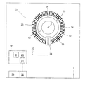
図1に示すのは、回転レーザ装置として構成されている本発明レーザ装置の一実施例を表す線図である。回転レーザ装置1は、ハウジング2、およびハウジング2内に設けられた、回転軸4を軸として回転可能なレーザユニット3を有する。
FIG. 1 is a diagram showing an embodiment of the laser apparatus of the present invention configured as a rotary laser apparatus. The
このレーザユニット3は、レーザビーム5を生成するものであり、光源6と、レーザビームのビーム形成を担う、ビーム形成光学系と呼ばれる光学素子7と、を有する。光源6は、例えば波長635nmの赤色レーザビームや、波長532nmの緑色レーザビームなどの可視スペクトルのレーザビーム5を生成する半導体レーザとして構成される。レーザビーム5が光源6出ると、レーザビーム5はビーム形成光学系7の助けを借りて平行になり、平行レーザビームが生成される。光源6は、第一制御ユニット8により制御される。
The
レーザユニット3は、レーザユニット3を所定回転速度で回転軸4を軸として動かす回転ユニット9と連結している。このとき、所定回転速度とは、一定でも良いし、変化するものとしても良い。回転ユニット9は回転可能なシャフト10、モータユニット11、および、モータユニット11の動力をシャフト10に伝動する、歯付きベルトで構成されたれた伝動ユニット12を有する。レーザユニット3は回転可能なシャフト10と連結されており、回転軸4を軸として回転可能である。回転ユニット9は第二制御ユニット13により制御される。
The
図1に示す実施形態において、光源6およびビーム形成光学系7は、回転ユニット9により回転軸4を軸として動かされる。代替の実施形態においては、レーザユニット3が、レーザビームの方向転換をするための、方向転換光学系と呼ばれる光学素子を更に有するものとしてもよい。この場合、光源6で生成されたレーザビームは、方向転換光学系で方向が決められる。方向転換光学系は、シャフト10と連結しており回転ユニット9により回転軸4を軸として動かされる。ビーム形成光学系7は、光源6と方向転換光学系との間に設けられる。また、ビーム形成光学系7は光源6に組み込まれるものとしてもよく、または、ビームの質が高くと発散が少ない光源6においては、省略することもできる。いずれにせよ、レーザユニット3の少なくとも1つの構成部材が回転ユニット9により回転軸4を軸として動かされる。
In the embodiment shown in FIG. 1, the light source 6 and the beam forming
回転レーザ装置1は、整準ユニット14を有し、この整準ユニット14により、レーザビームは、ハウジング2の姿勢に関係無く、重力方向と直交する水平面に延在し得る。水平面は、X軸およびY軸と呼ばれる互いに直交して延在する2軸上に広がる平面である。整準ユニット14は、X軸用の第一整準サブユニット15a、およびY軸用の第二整準サブユニット15bを有する。これら整準サブユニット15a,15bは、それぞれセンサ部および調整部を有する。整準ユニット14は第三制御ユニット16により制御される。
The
レーザビームが延在するレーザ平面は、水平面に対し、傾斜角度分傾けられ得る。この目的のため、シャフト10は、水平軸と直交する傾斜方向(X方向)の傾斜角度の調整をするための傾斜ユニット17により調整可能に構成されている。傾斜レーザ平面は、傾斜角度に関係なく常に平面内に保持されるY軸のの回りに傾けられ、したがってY軸に直交するX軸の方向(X方向)に沿って傾斜するよう方向設定される。傾斜ユニット17は第四制御ユニット18により制御される。
The laser plane from which the laser beam extends can be tilted by an inclination angle with respect to the horizontal plane. For this purpose, the
整準軸線X,Yは、回転レーザ装置1上では表示要素X’,Y’として表示される。理想的には、つまり、回転レーザ装置1の構成部材間に寸法誤差が無い状態では、X軸もしくはY軸と、回転レーザ装置1上に表示されるX’軸もしくはY’軸は、互いに平行である。回転レーザ装置1の構成部材間に寸法誤差がある場合にはX軸とX’軸との間、およびY軸とY’軸の間にずれが起こる。測定タスクによって、傾斜方向および水平方向の設定が確定され、回転レーザ装置1は、傾斜方向が(装置上に記された)X’軸に平行になるよう、そして、水平方向が(装置上に記された)Y’軸に平行に延在するように配置される。
The leveling axes X and Y are displayed as display elements X ′ and Y ′ on the
レーザユニット3を制御する第一制御ユニット8、回転ユニット9を制御する第二制御ユニット13、整準装置14を制御する第三制御ユニット16、傾斜ユニット17を制御する第四制御ユニット18は、個別の構成要素として構成されていても、または共通した1個の、例えばマイクロコントローラなどとして構成されるコントロールユニット19に組み込まれていても良い。これら制御ユニット8,13,16,18は通信リンク20を介して制御対象である要素6,9,14,17と接続している。
A
回転レーザ装置1は、レーザユニット3もしくはレーザビーム5の、回転軸4を軸とした回転中の回転角度を取得する測定ユニット21と、1または複数の回転角度を保存するためのデータ保存ユニット22とを有する。測定ユニット21は、シャフト10と一体回転するように連結された計測板23と、この計測板23をスキャンするためのスキャンユニット24と、評価・制御ユニット25と、から成る。この評価・制御ユニット25は、図1に示される実施形態例において、コントロールユニット19に組み込まれているが、代替として、別個の電子要素として構成されていても良い。データ保存ユニット22は、例えば、電子的データ保存ユニット、または、計測板23上に配置される参照要素の形態を取った機械的データ保存ユニットで構成される。
The
回転レーザ装置1から放射されたレーザビーム5は、対象面26上にレーザマーキングを生成する。このレーザマーキングを可視のものとするために、対象面26に配置されたレーザ受光器27が用いられる。レーザ受光器27は、通信リンク28を介して回転レーザ装置1と接続可能である。
The
回転レーザ装置1は、ハウジング2に組み込まれ、外部から操作可能な操作ユニット29を有する。ハウジング2に組み込まれた操作ユニット29の他に、通信リンクを介して回転レーザ装置1と接続可能である遠隔操作ユニットの形態をとった操作ユニットが更に設けられていても良い。遠隔操作ユニットは、例えばレーザ受光器27に組み込まれるものとする。
The
図2に示されるのは、レーザユニット3もしくはレーザビーム5の回転角度を取得するための測定ユニット21、および、機械的データ保存ユニット31として測定ユニット21の計測板23上に構成された、一または複数の角度位置を保存するためのデータ保存ユニットの第一実施形態である。
FIG. 2 shows a
測定ユニット21は、インクリメンタル回転エンコーダとして構成され、光電測定原理に基づくものとする。測定ユニット21の計測板23は、明ストライプ32と暗ストライプ33が交互に並ぶ、複数のセグメントを有する。これらのセグメント32,33は、インクリメントと呼ばれ、エンコーディングを具現化するための、いわゆるインクリメンタルトラック34を計測板23上に形成する。計測板23が完全に1回転すると、計測板23上のインクリメントの数に相応する数の電気信号が出力される。インクリメント32,33の数は測定ユニット21の分解能を規定し、各インクリメント32,33は、計測板23の角度単位にあたる。計測板23の精度は後から変更することはできない。
The
計測板23は、インクリメンタルトラック34の他に、第二トラック35を有し、この第二トラック35には、零点位置を固定する参照要素36(以降、零点素子36とする)が設けられている。第二トラックは、参照トラック35と呼ぶものとする。データ保存ユニット31は、計測板23に組み込まれ、参照要素の形態をとって計測板23上に構成される。計測板23は、インクリメンタルトラック34と参照トラック35の他に、第三トラック37および第四トラック38を有する。これらの第三および第四トラック37,38は共に機械的データ保存ユニット31を構成する。
The
第三トラック37は、0°である第一角度位置α1に対応する第一参照要素39と、90°である第二角度位置α2に対応する第二参照要素40とを有する。第一および第二参照要素39,40は、回転レーザ装置1のラインモードにおいて、対象面26に、ビーム広がり角度90°の有限線状レーザを生成するために用いられる。
The
第四トラック38は、他の角度位置Γに相応する、他の参照要素41を有する。回転レーザ装置1が対象面26に生成する、傾斜レーザマーキングの正確性を高めるために、傾斜方向がX軸に平行でかつ傾斜軸となるY軸に直交するような角度位置が、参照要素41としてデータ保存ユニット31に保存される。回転レーザ装置1の組立て後、装置製造者は、この角度位置Γを算出し、データ保存ユニット31に保存する。操作者は、測定ユニット21に組み込まれた保存ユニット31と、レーザ受光器27とを利用して、回転レーザ装置1を方向設定モードにて、傾斜方向がX軸に平行でY軸に直交するように配向されるように方向設定する。
The fourth track 38 has
図2に示された角度位置の他にも、任意の角度位置が参照要素として計測板23に設けられ、機械的保存ユニット31に保存されてもよい。いずれにせよ、参照要素として計測板23上に保存されるべき角度位置は、測定ユニット21の製造時において既に決定されていなければならない。角度位置を、後から変更や保存することはできない。このためデータ保存ユニット31は、特にこれらの使用時に頻繁に必要とされる角度位置に適している。例えば、90°や180°などの角度位置である。
In addition to the angular position shown in FIG. 2, an arbitrary angular position may be provided as a reference element on the
図3に、回転角度を取得するための測定ユニット21と、第二実施形態のデータ保存ユニット51として形成される電子的データ保存ユニットとを示す。対象面26から他の対象面26へと、任意の角度で移行するため、または任意のビーム広がり角度でレーザラインを生成するには、特に電子的データ保存ユニット51が適している。
FIG. 3 shows a
データ保存ユニット51は、測定ユニット21の評価・制御ユニット25と接続されており、またはこの代替として、評価・制御ユニット25に、共通の電子要素として構成されるものとしても良い。データ保存ユニット51に保存された各角度位置は、例えばレーザビーム5のビーム特性の制御に用いられ、データ保存ユニット51に常時固定値として保存されるものとしても、または操作者により入力ユニット52から入力され、一時的にのみデータ保存ユニット51に保存されるものとしても良い。入力ユニット52は、例えば回転レーザ装置1の操作ユニット29、またはレーザ受光器27に組み込まれるものとする。
The
図4Aに示されるのは、回転レーザ装置1と、測定ユニット21およびデータ保存ユニット31の助けを借りて回転レーザ装置1の方向設定をするレーザ受光器27とから成る設備である。角度位置Γは、参照要素41としてデータ保存ユニット31に保存される。操作者は、回転レーザ装置1の方向設定をするに際して、回転レーザ装置1およびレーザ受光器27の助けを借りる。角度位置Γは、操作者に対して、異なるレーザビーム5a,5b,5cにより視覚的に表示される。
Shown in FIG. 4A is equipment comprising a
回転角度の0°から360°は、0°からΓ−Δγの第一角度領域、Γ−ΔγからΓ+Δγの第二角度領域、および、Γ+Δγから360°の第三角度領域の、3つの角度領域に分けられる。値Δγは、一方では光源6のレーザ出力が切り替えられ得る正確性に応じて決められるものであり、他方、Γ−ΔγからΓ+Δγのレーザマーキングが操作者に良く見えるように決定される。 The rotation angle of 0 ° to 360 ° is divided into three angle regions: a first angle region from 0 ° to Γ-Δγ, a second angle region from Γ-Δγ to Γ + Δγ, and a third angle region from Γ + Δγ to 360 °. It is divided into. The value Δγ is determined on the one hand according to the accuracy with which the laser output of the light source 6 can be switched, and on the other hand, the laser marking from Γ−Δγ to Γ + Δγ is determined so that it can be seen well by the operator.
図4Bは、レーザ受光器27の基本的な要素、およびレーザ受光器27の回転レーザ装置1との相互作用をブロック図で示すものである。
FIG. 4B is a block diagram showing the basic elements of the
レーザ受光器27は、ハウジング61を有し、このハウジング61内には、操作ユニット62、レーザビーム5を検知するための検知ユニット63、および表示ユニット64が組み込まれている。検知ユニット63および表示ユニット64は、評価ユニット65と接続されている。この評価ユニット65は、レーザ受光器27の制御を担う制御ユニット66と接続されており、評価・制御ユニット65,66は、例えば、マイクロコントローラとして構成されたコントロールユニット67に組み込まれる。レーザ受光器27は、モードスイッチ68によって、異なる作動モードに切り替えられ得る。レーザ受光器27は、第一作動モードにおいては、回転レーザ装置1の方向設定を、第二作動モードにおいては、レーザビーム5の視覚的および/または聴覚的表示を、第三作動モードにおいては回転レーザ装置1の遠隔操作を担う。
The
レーザ受光器27と回転レーザ装置1とは、通信リンク28を介して通信し、具体的には、この通信リンク28は、レーザ受光器27の第一送受信ユニット69を回転レーザ装置1の第二送受信ユニット70と接続する。
The
回転レーザ装置1は、図1に示される要素の他に、操作者に調整指令を表示するための表示ユニット71を備える。表示ユニット71は、左矢印の形態をとった第一表示素子72、丸印の形態をとった第二表示素子73、および、右矢印の形態をとった第三表示素子74を有する。
The
左矢印72が点灯している場合、回転レーザ装置1が左方向に回転されなければならないことを操作者に示している。修正角度Γ±Δγが得られると、丸印73が点灯し、回転レーザ装置1の方向設定が無事終了したことを示す。右矢印74が点灯している場合は、回転レーザ装置1が右方向に回転されなければならないことを操作者に示している。
When the
図5A,5Bは、本発明に従う、操作者が、測定ユニット21およびレーザ受光器27を用いて、回転レーザ装置1を手動で方向設定する方法を示すフローチャートである。
5A and 5B are flowcharts showing a method in which the operator manually sets the direction of the
ステップS101において、操作者は、レーザ受光器27を所定の傾斜方向に配置し、操作ユニット62により、レーザ受光器27の方向設定モードを起動する。ステップS102においては、レーザ受光器27と回転レーザ装置1との間で通信リンク28が作動しているかが確認される。通信リンク28が作動していない場合(S102におけるN)、通信リンク28は、ステップS103にて起動される。レーザ受光器27と回転レーザ装置1との間で通信リンク28が既に作動している場合(S102におけるJ)、ステップS104へと移行する。
In step S <b> 101, the operator places the
ステップS104において、操作者は、回転レーザ装置1の操作ユニット29またはレーザ受光器27の操作ユニット62から、レーザ平面の傾斜角度を入力する。ステップS105において、傾斜角度は、レーザ受光器27から、通信リンク28を介して傾斜ユニット17の制御ユニット18に伝達される。ステップS106において、制御ユニット18は、対応する制御指令を傾斜ユニット17に伝え、ステップS107において、傾斜ユニット17は、シャフト10を所望の傾斜角度分傾ける。ステップS108において、制御ユニット18は傾きが合わせられたという情報をレーザ受光器27に伝える。
In step S104, the operator inputs the tilt angle of the laser plane from the
ステップS109において、レーザ受光器27の制御ユニット66に、光源6と回転ユニット9とが、連続的なレーザマーキングを対象面26に生成するように、との制御命令を伝える。ステップS110において、レーザビームは光源6から放射されるが、この際、制御ユニット8により、保存された角度位置Γと、回転ユニット9のその時点での回転角度とに基づいて、3つの異なる変調周波数で変調され、結果、3つのレーザビーム5a,5b,5cが異なる光周波数を持つようになる。0°からΓ−Δγまでの回転角度においては、レーザビーム5は、第一変調周波数F1で、Γ−ΔγからΓ+Δγまでの領域では第二変調周波数F2で、Γ+Δγから360°までの領域では第三変調周波数F3で変調される。
In step S109, the
ステップS111において、レーザ受光器27の検知ユニット63は、レーザビームを検知し、検知ユニット63に当たるレーザビームの光周波数を算出し、その光周波数を制御ユニット66に伝える。ステップS112において、制御ユニット66は、当該レーザビームの光周波数を算出し、これを、レーザビームが変調される変調周波数と比較する。
In step S111, the
図5Bは、ステップ112以降の、回転角度に依存してレーザビームが変調される、各変調周波数F1、F2およびF3における手続きを示すものである。
FIG. 5B shows the procedure at each modulation frequency F 1 , F 2 and F 3 after
レーザビームが第一変調周波数F1で変調されると、ステップS113において、制御ユニットは表示ユニット71に、右矢印74を点灯するように指令を与える。ステップS114において、右矢印74は点灯される。この視覚的教示に応じて、操作者は、ステップS115において回転レーザ装置1を時計回り方向に回転させる。その後、ステップS109へと移行する。
When the laser beam is modulated with the first modulation frequency F 1 , the control unit instructs the
レーザビームが第三変調周波数F3で変調されると、ステップS116において、制御ユニットは表示ユニット71に、左矢印72を点灯するように指令を与える。ステップS117において、左矢印72は点灯される。この視覚的教示に応じて、操作者は、ステップ118において回転レーザ装置1を反時計回り方向に回転させる。その後、ステップS109へと移行する。
When the laser beam is modulated at the third modulation frequency F 3 , the control unit instructs the
レーザビームが第二変調周波数F2で変調されると、ステップ119において、制御ユニットは表示ユニット71に、丸印73を点灯するように指令を与える。ステップS120において、丸印73は点灯される。回転レーザ装置1の方向設定方法はステップS120で終了する。
When the laser beam is modulated with the second modulation frequency F 2 , in
図6に示されるのは、代替実施形態における、測定ユニット21およびレーザ受光器27を用いた回転レーザ装置1の手動方向設定方法である。ここでは、回転レーザ装置115は、スキャンモードで作動する。スキャンモードにおいて、レーザビーム5は、第一折返し点W1と第二折返し点W2の間の限定的角度領域を往復運動する。レーザビーム5は、対象面26上に有限の線状レーザを生成する。
FIG. 6 shows a manual direction setting method for the
この方法では、測定タスクにより予め得られた傾斜方向75が、傾斜軸X軸に平行でY軸に直交する向きに対応する角度位置Γが、検知ユニット63の中央に来るように回転レーザ装置1を方向設定する。レーザ受光器27は、検知ユニット63の中央および回転軸4を通る直線が、傾斜方向75に対して平行に延在するように対象面26上に配置される。水平方向76は傾斜方向75に直交するように設けられる。
In this method, the
回転レーザ装置1は、レーザ受光器27の指令に対して、角度位置Γから両側にそれぞれ向かって同じ角度だけ離れた折返し点W1,W2の間の限定的レーザラインを生成する。レーザ受光器27は、レーザビーム5が、検知ユニット63から第一折返し点W1まで、また、そこから検知ユニット63に帰ってくるまでの道のりにかかる時間間隔T1、および、レーザビーム5が、検知ユニット63から第二折返し点W2まで、また、そこから検知ユニット63に帰ってくるまでの道のりにかかる時間間隔T2を算出する。
In response to the command from the
回転レーザ装置1は、時間間隔T1とT2とが等しい場合に、角度位置Γに位置することになる。これは、点灯した丸印73により操作者に示される。図6に示されるように、時間間隔T1がT2より小さい場合、左矢印72が点灯し、操作者に回転レーザ装置1が、回転軸4を軸として反時計回り、すなわち左方向に回転させられなければならないことを示す。時間間隔T1は時間間隔T2より大きい場合には、回転レーザ装置1は、回転軸4を軸として時計回り、すなわち右方向に回転させられなければならない。この調整指令は、点灯した右矢印74によって操作者に示される。
The
図7に示されるのは、代替バリエーションにおける、自動調整ユニット81を用いた、回転レーザ装置1の方向設定である。このバリエーションにおける方法は、図5A,Bに示される手動方法に対して、操作者の負担が最小限に抑えられるという利点を有する。操作者は、回転レーザ装置1の方向設定方法が終了するのを待つだけで良い。
FIG. 7 shows the direction setting of the
図7に示されるバリエーションにおいて、回転レーザ装置は調整ユニット81に取り付けられ、回転軸4を軸として回転される。この代替の実施形態において、調整ユニット81は、回転レーザ装置1のハウジング2に設けられていても良い。この場合には、シャフト10およびシャフト10と回転一体に連結された要素は、回転軸4を軸として、ハウジング2に対して相対的に回転させられる。
In the variation shown in FIG. 7, the rotary laser device is attached to the
回転レーザ装置1は、通信リンク82を介して調整ユニット81と接続される。方向設定モードにおいて、データ保存ユニットに保存された角度位置Γは、通信リンク82を介して調整ユニット81に伝達される。調整ユニット81は、回転レーザ装置1を、所定の傾斜方向75が、傾斜軸X軸に平行でY軸に直交するような角度位置Γへと回転させる。
The
1 回転レーザ装置
2 ハウジング
3 レーザユニット
4 回転軸
5 レーザビーム
6 光源
7 ビーム形成光学系
8 第一制御ユニット
9 回転ユニット
10 シャフト
11 モータユニット
12 伝動ユニット
13 第二制御ユニット
14 整準ユニット
15a 第一整準サブユニット
15b 第二整準サブユニット
16 第三制御ユニット
17 傾斜ユニット
18 第四制御ユニット
19 コントロールユニット
21 測定ユニット
22 データ保存ユニット
23 計測板
24 スキャンユニット
25 評価・制御ユニット
26 対象面
27 レーザ受光器
28 通信リンク
29 操作ユニット
31 機械的データ保存ユニット
32 明ストライプ
33 暗ストライプ
39 参照要素
40 参照要素
41 参照要素
51 電子的データ保存ユニット
52 入力ユニット
71 表示ユニット
72 第一表示素子
73 第三表示素子
74 第二表示素子
81 自動調整ユニット
DESCRIPTION OF
Claims (16)
前記レーザビーム(5)が、重力方向に対して直交する水平面(X,Y)内に向くようレベル調整する整準ユニット(14)、
前記レーザビーム(5)を、前記水平面(X,Y)に対して、傾斜方向(X軸方向)に傾斜させる傾斜ユニット(17)、
前記レーザユニット(3)を、所定回転速度で、回転軸(4)の回りを少なくとも部分的に回転させる回転ユニット(9)、および、
前記レーザユニット(3)の前記回転軸(4)の回りの回転角度を算出することのできる測定ユニット(21)、
を有する該回転レーザ装置(1)において、
前記回転角度における、少なくとも1つの角度位置(α1,α2,Γ)を保存するためのデータ保存ユニット(22;31;51)を備えていることを特徴とする回転レーザ装置(1)。 A laser unit (3) for generating a laser beam (5);
A leveling unit (14) for level adjustment so that the laser beam (5) is directed in a horizontal plane (X, Y) perpendicular to the direction of gravity;
An inclination unit (17) for inclining the laser beam (5) in an inclination direction (X-axis direction) with respect to the horizontal plane (X, Y);
A rotation unit (9) for rotating the laser unit (3) at least partially around a rotation axis (4) at a predetermined rotational speed; and
A measurement unit (21) capable of calculating a rotation angle of the laser unit (3) around the rotation axis (4);
In the rotary laser device (1) having:
A rotary laser device (1) comprising a data storage unit (22; 31; 51) for storing at least one angular position (α1, α2, Γ) at the rotation angle.
前記回転レーザ装置(1)を、回転軸(4)の回りに、前記傾斜方向(X軸方向)が所与の傾斜方向(75)に平行に向くような角度位置(Γ)へ回転させて、回転レーザ装置(1)の方向を設定する方法において、
前記傾斜方向(X軸方向)が所与の傾斜方向(75)に平行に向く前記角度位置(Γ)をデータ保存ユニット(22;31;51)に保存することを特徴とする方法。 When setting the direction of the rotating laser device (1), the laser beam (5) is tilted (X-axis direction) with respect to the horizontal plane (X, Y) perpendicular to the gravity direction by the tilting unit (17). Tilt and
The rotating laser device (1) is rotated around an axis of rotation (4) to an angular position (Γ) such that the tilt direction (X-axis direction) is parallel to a given tilt direction (75). In the method of setting the direction of the rotary laser device (1),
A method of storing the angular position (Γ) in which the tilt direction (X-axis direction) is parallel to a given tilt direction (75) in a data storage unit (22; 31; 51).
Applications Claiming Priority (2)
| Application Number | Priority Date | Filing Date | Title |
|---|---|---|---|
| DE102010061725A DE102010061725A1 (en) | 2010-11-22 | 2010-11-22 | Rotary laser device having a tilted laser plane and method of aligning a rotary laser device |
| DE102010061725.3 | 2010-11-22 |
Publications (1)
| Publication Number | Publication Date |
|---|---|
| JP2012112953A true JP2012112953A (en) | 2012-06-14 |
Family
ID=44799877
Family Applications (1)
| Application Number | Title | Priority Date | Filing Date |
|---|---|---|---|
| JP2011254069A Pending JP2012112953A (en) | 2010-11-22 | 2011-11-21 | Rotating laser device and method for aligning rotating laser device |
Country Status (4)
| Country | Link |
|---|---|
| US (1) | US8869411B2 (en) |
| EP (1) | EP2455711A3 (en) |
| JP (1) | JP2012112953A (en) |
| DE (1) | DE102010061725A1 (en) |
Cited By (4)
| Publication number | Priority date | Publication date | Assignee | Title |
|---|---|---|---|---|
| JP2015068743A (en) * | 2013-09-30 | 2015-04-13 | 株式会社トプコン | Rotation laser emission device and laser surveying system |
| WO2017146115A1 (en) * | 2016-02-22 | 2017-08-31 | 株式会社マキタ | Laser marking device |
| JP2019519788A (en) * | 2016-06-30 | 2019-07-11 | ヒルティ アクチエンゲゼルシャフト | Method for comparing a received beam and a rotating laser beam incident on a laser receiver |
| JP2019519789A (en) * | 2016-06-30 | 2019-07-11 | ヒルティ アクチエンゲゼルシャフト | Method for comparing a received beam incident on a laser receiver with a rotating laser beam |
Families Citing this family (6)
| Publication number | Priority date | Publication date | Assignee | Title |
|---|---|---|---|---|
| DE102010031634A1 (en) * | 2010-07-21 | 2012-01-26 | Hilti Aktiengesellschaft | Laser device and method for adjusting the laser power |
| DE102010061725A1 (en) * | 2010-11-22 | 2012-05-24 | Hilti Aktiengesellschaft | Rotary laser device having a tilted laser plane and method of aligning a rotary laser device |
| US9127935B2 (en) * | 2012-01-04 | 2015-09-08 | Chris Olexa | Laser centering tool for surface areas |
| EP3173740A1 (en) * | 2015-11-30 | 2017-05-31 | HILTI Aktiengesellschaft | Method for measuring a distance between a rotation laser and a laser receiver |
| GB202014590D0 (en) * | 2020-09-16 | 2020-10-28 | Stanley Works Israel | Laser tool and system |
| EP4256273A1 (en) | 2020-12-01 | 2023-10-11 | Milwaukee Electric Tool Corporation | Laser level interface and control |
Citations (4)
| Publication number | Priority date | Publication date | Assignee | Title |
|---|---|---|---|---|
| JPH05288547A (en) * | 1992-04-14 | 1993-11-02 | Kajima Corp | Three-dimensional positioning and shape measuring method for structure and the like |
| JPH09257478A (en) * | 1996-03-19 | 1997-10-03 | Topcon Corp | Laser survey apparatus |
| JP2001105356A (en) * | 1999-10-08 | 2001-04-17 | Yurtec Corp | Marking device |
| JP2005024450A (en) * | 2003-07-04 | 2005-01-27 | Sokkia Co Ltd | Laser survey apparatus |
Family Cites Families (20)
| Publication number | Priority date | Publication date | Assignee | Title |
|---|---|---|---|---|
| JPH032513A (en) * | 1989-05-30 | 1991-01-08 | Tatsushi Miyahara | Automatic surveying equipment |
| US5402223A (en) | 1992-09-24 | 1995-03-28 | Smart Grade Incorporated | Electronic survey stadia |
| DE4324478A1 (en) | 1993-07-21 | 1995-01-26 | Ralf Dr Hinkel | Rotational laser with improved visibility |
| JP3483303B2 (en) * | 1994-06-21 | 2004-01-06 | 株式会社トプコン | Rotary laser device |
| EP0722080B1 (en) | 1995-01-11 | 2000-03-15 | Kabushiki Kaisha Topcon | Laser levelling device |
| US6171018B1 (en) * | 1997-11-10 | 2001-01-09 | Kabushiki Kaisha Topcon | Automatic control system for construction machinery |
| EP1001251A1 (en) * | 1998-11-10 | 2000-05-17 | Leica Geosystems AG | Laser positioning system |
| JP4356050B2 (en) * | 2000-12-28 | 2009-11-04 | 株式会社トプコン | Surveyor and electronic storage medium |
| JP3816807B2 (en) | 2002-01-21 | 2006-08-30 | 株式会社トプコン | Position measuring device and rotating laser device used therefor |
| JP2004093504A (en) * | 2002-09-03 | 2004-03-25 | Topcon Corp | Surveying device |
| JP4354343B2 (en) | 2004-06-15 | 2009-10-28 | 株式会社トプコン | Position measurement system |
| CN101535764B (en) | 2006-11-03 | 2013-01-16 | 特林布尔凯泽斯劳滕有限公司 | Grade indicating device and method |
| JP5207665B2 (en) | 2007-06-08 | 2013-06-12 | 株式会社トプコン | Measuring system |
| EP2053353A1 (en) | 2007-10-26 | 2009-04-29 | Leica Geosystems AG | Distance measuring method and corresponding device |
| EP2144037A1 (en) * | 2008-07-10 | 2010-01-13 | Leica Geosystems AG | Construction laser, in particular a self-compensating rotating construction laser, and method for measuring a tilt of an axis of rotation of a construction laser |
| JP5456532B2 (en) * | 2010-03-25 | 2014-04-02 | 株式会社トプコン | Rotating laser device and rotating laser system |
| US8943701B2 (en) * | 2010-06-28 | 2015-02-03 | Trimble Navigation Limited | Automated layout and point transfer system |
| DE102010031634A1 (en) | 2010-07-21 | 2012-01-26 | Hilti Aktiengesellschaft | Laser device and method for adjusting the laser power |
| DE102010061725A1 (en) * | 2010-11-22 | 2012-05-24 | Hilti Aktiengesellschaft | Rotary laser device having a tilted laser plane and method of aligning a rotary laser device |
| DE102010061726A1 (en) * | 2010-11-22 | 2012-05-24 | Hilti Aktiengesellschaft | Rotary laser apparatus and method for controlling a laser beam |
-
2010
- 2010-11-22 DE DE102010061725A patent/DE102010061725A1/en not_active Ceased
-
2011
- 2011-10-18 EP EP11185633.2A patent/EP2455711A3/en not_active Ceased
- 2011-11-18 US US13/300,339 patent/US8869411B2/en active Active
- 2011-11-21 JP JP2011254069A patent/JP2012112953A/en active Pending
Patent Citations (4)
| Publication number | Priority date | Publication date | Assignee | Title |
|---|---|---|---|---|
| JPH05288547A (en) * | 1992-04-14 | 1993-11-02 | Kajima Corp | Three-dimensional positioning and shape measuring method for structure and the like |
| JPH09257478A (en) * | 1996-03-19 | 1997-10-03 | Topcon Corp | Laser survey apparatus |
| JP2001105356A (en) * | 1999-10-08 | 2001-04-17 | Yurtec Corp | Marking device |
| JP2005024450A (en) * | 2003-07-04 | 2005-01-27 | Sokkia Co Ltd | Laser survey apparatus |
Cited By (5)
| Publication number | Priority date | Publication date | Assignee | Title |
|---|---|---|---|---|
| JP2015068743A (en) * | 2013-09-30 | 2015-04-13 | 株式会社トプコン | Rotation laser emission device and laser surveying system |
| WO2017146115A1 (en) * | 2016-02-22 | 2017-08-31 | 株式会社マキタ | Laser marking device |
| JP2019519788A (en) * | 2016-06-30 | 2019-07-11 | ヒルティ アクチエンゲゼルシャフト | Method for comparing a received beam and a rotating laser beam incident on a laser receiver |
| JP2019519789A (en) * | 2016-06-30 | 2019-07-11 | ヒルティ アクチエンゲゼルシャフト | Method for comparing a received beam incident on a laser receiver with a rotating laser beam |
| US10823566B2 (en) | 2016-06-30 | 2020-11-03 | Hilti Aktiengesellschaft | Method for comparing a received beam hitting a laser receiver with a rotating laser beam |
Also Published As
| Publication number | Publication date |
|---|---|
| US8869411B2 (en) | 2014-10-28 |
| US20120124851A1 (en) | 2012-05-24 |
| EP2455711A3 (en) | 2014-07-02 |
| DE102010061725A1 (en) | 2012-05-24 |
| EP2455711A2 (en) | 2012-05-23 |
Similar Documents
| Publication | Publication Date | Title |
|---|---|---|
| JP2012112953A (en) | Rotating laser device and method for aligning rotating laser device | |
| JP6560596B2 (en) | Surveying equipment | |
| US10684129B2 (en) | Method for checking and/or calibrating a horizontal axis of a rotating laser | |
| CN105424011B (en) | Measuring device and method for setting measuring device | |
| US10697796B2 (en) | Method for checking and/or calibrating a vertical axis of a rotating laser | |
| JP6675485B2 (en) | How to inspect cone errors in rotating lasers | |
| US7861427B2 (en) | Grade indicating device and method | |
| JP6553999B2 (en) | Polygon mirror and fan beam output device and surveying system | |
| US11953322B2 (en) | Method for checking and/or calibrating a horizontal axis of a rotating laser | |
| KR20130087031A (en) | Device for measuring and marking space points along horizontally running contour lines | |
| WO2012013280A1 (en) | Device for optically scanning and measuring an environment | |
| JP2019100915A (en) | Measurement device, measurement device calibration method, and measurement device calibration-purpose program | |
| JP4996371B2 (en) | Automatic leveling device for surveying instruments | |
| JP6864653B2 (en) | Vertical measurement system and reference point tracing method | |
| JP2016050775A (en) | Measuring apparatus and inclination sensor apparatus | |
| US6693706B2 (en) | Laser reference system and method of determining grade rake | |
| KR20190053747A (en) | Measuring Instrument for Sizing Object at Long Distance | |
| US11448504B2 (en) | Surveying device | |
| US20120127553A1 (en) | Rotary Laser Device and Method for Controlling a Laser Beam | |
| US20210285766A1 (en) | Optical surveying instrument with movable mirror | |
| US8605274B2 (en) | Laser reference system | |
| JP2010156659A (en) | Calibration method and calibration program of laser marker, and electronic gyro system laser marker | |
| JP2006292497A (en) | Surveying system and its handling method | |
| US11674800B2 (en) | Laser level meter and use method therefor | |
| CN109387827B (en) | Tracking method for tracking a laser receiver in a laser transmitter |
Legal Events
| Date | Code | Title | Description |
|---|---|---|---|
| A621 | Written request for application examination |
Free format text: JAPANESE INTERMEDIATE CODE: A621 Effective date: 20141001 |
|
| A977 | Report on retrieval |
Free format text: JAPANESE INTERMEDIATE CODE: A971007 Effective date: 20150723 |
|
| A131 | Notification of reasons for refusal |
Free format text: JAPANESE INTERMEDIATE CODE: A131 Effective date: 20150819 |
|
| A601 | Written request for extension of time |
Free format text: JAPANESE INTERMEDIATE CODE: A601 Effective date: 20151118 |
|
| A601 | Written request for extension of time |
Free format text: JAPANESE INTERMEDIATE CODE: A601 Effective date: 20151218 |
|
| A601 | Written request for extension of time |
Free format text: JAPANESE INTERMEDIATE CODE: A601 Effective date: 20160118 |
|
| A02 | Decision of refusal |
Free format text: JAPANESE INTERMEDIATE CODE: A02 Effective date: 20160427 |