JP2012108894A - Capacitance type touch pen - Google Patents
Capacitance type touch pen Download PDFInfo
- Publication number
- JP2012108894A JP2012108894A JP2011234486A JP2011234486A JP2012108894A JP 2012108894 A JP2012108894 A JP 2012108894A JP 2011234486 A JP2011234486 A JP 2011234486A JP 2011234486 A JP2011234486 A JP 2011234486A JP 2012108894 A JP2012108894 A JP 2012108894A
- Authority
- JP
- Japan
- Prior art keywords
- input
- fiber
- touch pen
- conductive
- tip
- Prior art date
- Legal status (The legal status is an assumption and is not a legal conclusion. Google has not performed a legal analysis and makes no representation as to the accuracy of the status listed.)
- Granted
Links
Images


Abstract
Description
本発明は、パソコン、携帯端末などの情報処理装置に接続された静電容量型入力パッドに座標情報を入力するための静電容量型入力パッド用のタッチペンに関する。 The present invention relates to a touch pen for a capacitive input pad for inputting coordinate information to a capacitive input pad connected to an information processing apparatus such as a personal computer or a portable terminal.
従来、静電入力型タッチペンとしては、導電性を持つ把持部と、その把持部に電気的に接続する導電性を持つペン先を備えたものが提案されている(例えば特許文献1)。このような構成は、正確な座標を入力出来、入力パッドを傷めることの少ないタッチペンとして、この当時としては重宝されるものであった。しかしながら、昨今の技術的進歩により、入力パッドの盤面上の座標をより細かい解析が可能になると、このような構成のタッチペンによる接触は、押し付けられ変形して密着した「面」での接触と認識されてしまうこととなる。このことは、ある程度の面積を持ったアイコン等へのタッチであれば問題は無いが、例えば、描画を行う際に、ごく細い線を入力したい場合には支障を来たしてしまう。
また、導電性を持つペン先の例として、軸尖端の部分に導電性フェルト布を巻いたペン(特許文献1の図2)、軸尖端の部分に導電性繊維の植毛を施したペン(特許文献1の図3)が開示されているが、これらの導電性フェルト布あるいは導電性繊維の植毛が摩耗してしまうと、把持部との導電性が失われ、その再生が困難である。
2. Description of the Related Art Conventionally, as an electrostatic input type touch pen, one having a conductive gripping part and a conductive pen tip that is electrically connected to the gripping part has been proposed (for example, Patent Document 1). Such a configuration was useful at this time as a touch pen that can input accurate coordinates and hardly damage the input pad. However, if recent technological advances enable finer analysis of the coordinates of the input pad on the board surface, contact with a touch pen with such a configuration will be recognized as contact on a "surface" that has been pressed and deformed. It will be done. This is not a problem as long as an icon or the like having a certain area is touched. However, for example, when a very thin line is desired to be drawn, a problem occurs.
Moreover, as an example of a conductive nib, a pen in which a conductive felt cloth is wound around the tip of the shaft (FIG. 2 of Patent Document 1), and a pen in which conductive fiber is implanted in the tip of the shaft (patent FIG. 3) of
通常の紙への筆記においては、毛筆を用いれば、ごく細い線から太い線へ、逆に太い線からごく細い線へ、線幅を変更することは容易である。このような、いわゆる筆文字入力を可能にした入力用のペンも開示されている(特許文献2)。これは、ペン体内に設けられた受信器によって入力パッドからの信号を受信し、入力パッドからの距離を計算して筆圧の強弱を判断するものである。この方法であると、入力パッド上に描いたつもりの描線が、入力パッドからの距離から計算された描線に判断されて表示されてしまう欠点がある。 In writing on normal paper, if a brush is used, it is easy to change the line width from a very thin line to a thick line, and conversely from a thick line to a very thin line. Such an input pen that enables so-called calligraphy input is also disclosed (Patent Document 2). In this method, a signal from the input pad is received by a receiver provided in the pen body, and the distance from the input pad is calculated to determine the strength of the writing pressure. With this method, there is a drawback that the drawn line intended to be drawn on the input pad is displayed as judged by the drawn line calculated from the distance from the input pad.
入力パッドからのアナログ的な入力、即ち、毛筆や絵筆で描いたような、ごく細い描線から筆幅一杯の太い線まで、線幅を変更しながら描くような入力、あるいは、「止め」や「跳ね」などを行った際に、極めて予測不可能かつランダムに「掠れた」描線が求められるような場面においては、上記従来のタッチペンでは入力を行うことが出来ない。 Analog input from the input pad, that is, input that changes the line width from a very thin stroke to a full stroke, such as drawn with a brush or paintbrush, or “stop” or “ When the “bounce” or the like is performed, it is impossible to input with the above-mentioned conventional touch pen in a scene where a “drawn” drawing line that is extremely unpredictable and random is required.
即ち、本発明は次の(1)〜(5)に存する。
(1)テーパ繊維からなる入力尖端を持つ入力用タッチペンであり、
前記テーパ繊維表面には導電性樹脂の被覆を持つことを特徴とする入力用タッチペン。
(2)上記入力尖端は前記テーパ繊維を収束させた繊維束体であることを特徴とする上記(1)記載の入力用タッチペン。
(3)上記繊維束体の尖端は穂筆であることを特徴とする上記(1)または(2)の何れか一つに記載の入力用タッチペン。
(4)上記テーパ繊維は基端に被係止部が形成され、上記入力用タッチペン本体に備わる係止部に対して着脱自在であることを特徴とする上記(1)記載の入力用タッチペン。
(5)上記テーパ繊維を収束させた繊維束体は基端に被係止部が形成され、上記入力用タッチペン本体に備わる係止部に対して着脱自在であることを特徴とする上記(2)または(3)の何れか一つに記載の入力用タッチペン。
That is, the present invention resides in the following (1) to (5).
(1) An input touch pen having an input tip made of a tapered fiber,
An input touch pen, wherein the taper fiber surface has a conductive resin coating.
(2) The input touch pen according to (1), wherein the input tip is a fiber bundle in which the tapered fibers are converged.
(3) The touch pen for input according to any one of (1) and (2), wherein a tip of the fiber bundle is a brush.
(4) The input touch pen according to (1), wherein the tapered fiber has a locked portion formed at a base end and is detachable from a locking portion provided in the input touch pen body.
(5) The fiber bundle in which the tapered fibers are converged has a locked portion formed at a base end, and is detachable from the locking portion provided in the input touch pen body (2) ) Or the touch pen for input according to any one of (3).
本発明のタッチペンを用いれば、入力パッドから、アナログ的な入力、即ち、毛筆や絵筆で描いたような、ごく細い描線から筆幅一杯の太い線まで、線幅を変更しながら描くような入力、あるいは、「止め」や「跳ね」などを行った際に、極めて予測不可能かつランダムに「掠れた」描線を入力することが出来る。 With the touch pen of the present invention, analog input from the input pad, that is, input that draws while changing the line width from a very thin stroke to a full stroke of the stroke, such as drawn with a brush or paint brush Or, when “stopping” or “bounce” is performed, it is possible to input a drawn line that is very unpredictable and randomly drawn.
以後は、入力用タッチペンの軸方向尖端側を先方、逆側を後方として説明を行う。
本発明で用いるテーパ繊維の基材としては、天然繊維、獣毛繊維、ポリアセタール系樹脂、アクリル系樹脂、ポリエステル系樹脂、ポリアミド系樹脂、ポリウレタン系樹脂、ポリオレフィン系樹脂、ポリビニル系樹脂、ポリカーボネート系樹脂、ポリエーテル系樹脂、ポリフェニレン系樹脂などの1種又は2種以上の組み合わせからなる繊維体からなるものが挙げられる。これらの樹脂に導電性の炭素材等を混練してテーパ繊維を形成し後、導電性を持つテーパ状の繊維としようとすると、異物が混練された状態であるため、細く成形する途中で形状を維持できなくなりボロボロに崩壊してしまう。そこで、前記列挙したような、ごく普通のテーパ繊維に導電性樹脂の被膜を持たせる方が、安価に製造出来るうえ、再利用も簡単に出来る。これらの繊維の抵抗値は1010Ω/cm以下であることが望ましい。また、これらの繊維を使用して穂筆を構成する場合、繊維の少なくとも一部をこの導電性繊維としてもよく、穂筆の全ての繊維を導電性繊維とすることもできる。 As the base material of the taper fiber used in the present invention, natural fiber, animal hair fiber, polyacetal resin, acrylic resin, polyester resin, polyamide resin, polyurethane resin, polyolefin resin, polyvinyl resin, polycarbonate resin , Polyether fibers, polyphenylene resins, and the like, or a combination of two or more types of fibrous bodies. After forming a tapered fiber by kneading a conductive carbon material or the like with these resins, when trying to make a tapered fiber with conductivity, the foreign material is kneaded, so the shape is formed in the middle of thin molding It becomes impossible to maintain and collapses tattered. Therefore, it is possible to manufacture at a lower cost and to reuse easily by providing a conductive resin coating on ordinary taper fibers as listed above. The resistance value of these fibers is desirably 10 10 Ω / cm or less. Moreover, when using these fibers to construct a brush, at least a part of the fibers may be the conductive fiber, and all the fibers of the brush can be made conductive.
また、テーパ繊維の導電性被膜に用いられる導電性材料は、ポリピロール、ポリチオフェン、ポリエチレンジオキシチオフェン、ポリイソチアナフテン、ポリアニリンなどの導電性樹脂を分散または可溶化させた樹脂溶液をテーパ繊維に塗布し、固化または加熱硬化させることにより得られる。これらの導電性材料を用いる際に、導電性を適宜調整するために、2,3,7,8−テトラシアノ−1,4,6,9−テトラアザナフタレン、ドデシルベンゼンスルホン酸、p−トルエンスルホン酸などのドーパントを添加した導電性樹脂を使用することができる。 In addition, the conductive material used for the conductive coating on the tapered fiber is a resin solution in which a conductive resin such as polypyrrole, polythiophene, polyethylenedioxythiophene, polyisothianaphthene, or polyaniline is dispersed or solubilized is applied to the tapered fiber. And solidified or heat cured. When using these conductive materials, 2,3,7,8-tetracyano-1,4,6,9-tetraazanaphthalene, dodecylbenzenesulfonic acid, p-toluenesulfone are used in order to appropriately adjust the conductivity. A conductive resin to which a dopant such as an acid is added can be used.
また、前記繊維に用いることができる導電性材料として、一般的な導電性材料であるカーボンブラック、黒鉛、および、金属粒子等も用いることができる。前記した通り全体がこのような材料からなる繊維では、入力パネルを傷付ける等の問題が出てくるが、ポリエステル、ポリアミドなどの合成繊維の表面を被覆したり、繊維の一部に上記の導電性材料を用いた場合、繊維としての柔軟性を調整すれば、このような問題を回避できる。 Moreover, as a conductive material that can be used for the fiber, carbon black, graphite, metal particles, and the like, which are general conductive materials, can also be used. As described above, the fiber made of such a material as a whole may cause problems such as scratching the input panel. However, the surface of synthetic fiber such as polyester or polyamide may be covered, or a part of the fiber may have the above conductivity. When the material is used, such a problem can be avoided by adjusting the flexibility of the fiber.
このように導電性材料によって被覆されたテーパ繊維は、軸筒に固定しやすいように、その後端に被係止部を設けることができる。 Thus, the taper fiber coat | covered with the electroconductive material can provide a to-be-latched part in the rear end so that it may be easy to fix to a shaft cylinder.
前記したようなテーパ繊維を繊維束(穂筆)として形成させ、ブラシ状あるいは穂筆状として使用することも出来る。テーパ繊維の後端側を、前記の導電性材料などで固化して束ねる事により、繊維束(穂筆)として形成させることが出来る。また、テーパ繊維が熱可塑性樹脂からなるものであれば、繊維の後端を熱融着させ、束ねて繊維束(穂筆)として形成させることも出来る。
これらの繊維束(穂筆)の後端には、前記の繊維単独の場合と同様に被係止部を設けることができる。本願では、被係止部は鍔状であって、軸筒先端の係止部に嵌着されている。
The taper fibers as described above can be formed as a fiber bundle (brush brush) and used as a brush shape or a brush shape. A tape bundle fiber can be formed as a fiber bundle (handbrush) by solidifying and bundling the rear end side of the taper fiber with the conductive material. Further, if the tapered fiber is made of a thermoplastic resin, the rear end of the fiber can be thermally fused and bundled to form a fiber bundle (handbrush).
At the rear end of these fiber bundles (hand brushes), a locked portion can be provided as in the case of the fibers alone. In this application, the to-be-latched part is hook-like and is fitted to the latching part at the tip of the shaft tube.
ペンの軸体は、導電性繊維の繊維束(穂筆)が十分に大きければ、導電性のない材料からなる軸体でも静電容量型座標入力装置または表示一体型静電容量型入力装置に入力が可能である。ただし、繊維束(穂筆)が小さい場合や、静電容量型座標入力装置または表示一体型静電容量型入力装置の応答性能が劣る場合、カーボンブラックや金属微粒子などを配合した合成樹脂軸や、合成樹脂軸表面にめっきをほどこした軸や、導電性金属からなる軸を用いることにより、軸体の把持部とペン先が導電性を有するような軸体が得られる。また、ペン先〜軸体を導通させる場合、軸体は、軸体の把持部とペン先が導電性を有していれば、1部品単体で構成、または、先軸、軸筒、尾栓などの複数部品により構成してもよいし、あるいは、先軸、軸筒などの部材の外周部にカーボンブラックや金属微粒子などを配合した合成樹脂を被覆したり、めっきをほどこしたり、導電性金属からなる被覆を施したり、又は、前記の導電性材料の被覆を施してもよい。更には、軸体内部に、ペン先と導通するように、導電性繊維、導電性スポンジ、金属、グラファイト焼結体などの導電体を収納しておくことで、導電体の体積を増大させ、静電容量型座標入力装置または表示一体型静電容量型入力装置の応答性を適宜調整することができる。 As long as the shaft of the pen is sufficiently large, the shaft made of a non-conductive material can be used as a capacitive coordinate input device or a display-integrated capacitive input device. Input is possible. However, when the fiber bundle (hand brush) is small, or when the response performance of the capacitive coordinate input device or the display-integrated capacitive input device is inferior, a synthetic resin shaft containing carbon black or metal fine particles, By using a shaft obtained by plating the surface of the synthetic resin shaft or a shaft made of a conductive metal, a shaft body in which the grip portion of the shaft body and the pen tip have conductivity can be obtained. In addition, when the pen tip to the shaft body are made conductive, the shaft body is constituted by a single component as long as the grip portion of the shaft body and the pen tip have conductivity, or the tip shaft, shaft cylinder, tail plug It may be composed of multiple parts such as, or the outer periphery of a member such as a tip shaft or a shaft tube may be coated with a synthetic resin containing carbon black or metal fine particles, plated, or conductive metal You may give the coating which consists of, or the coating of the said electroconductive material. Furthermore, by storing a conductor such as conductive fiber, conductive sponge, metal, graphite sintered body so as to be electrically connected to the pen tip inside the shaft body, the volume of the conductor is increased, The responsiveness of the capacitive coordinate input device or the display-integrated capacitive input device can be appropriately adjusted.
このように構成されたペンを用いて静電容量型座標入力装置または表示一体型静電容量型入力装置に座標を入力する場合、使用者は、軸体を把持し、ペン先を静電容量型座標入力装置または表示一体型静電容量型入力装置に押し当てることで入力する。この結果、静電容量型座標入力装置または表示一体型静電容量型入力装置とペン先先端の間に、正確な接触面積に依存した企図される静電容量が形成され、正確な入力が可能となる。
このテーパ繊維の曲げ強度等、繊維束(穂筆)の固さ等を調整することによって、使用者にとって適切な入力時の感触にすることが可能となる。即ち、テーパ繊維の曲げ強度等あるいは繊維束(穂筆)の固さ等の変更によって曲げ強度及び可撓性を希望する値に調整し、使用者にとって適切な「筆記抵抗」や「入力感」とすることが容易となる。この際、テーパ繊維あるいは繊維束(穂筆)からなる筆記尖端を着脱可能としておくことにより、これらの交換による「筆記抵抗」や「入力感」の調整が、より容易となる。
When inputting coordinates to the capacitive coordinate input device or the display-integrated capacitive input device using the pen configured as described above, the user holds the shaft body and places the pen tip on the electrostatic capacitance. Input is performed by pressing against a type coordinate input device or a display-integrated capacitance type input device. As a result, an intended capacitance depending on the exact contact area is formed between the capacitive coordinate input device or the display-integrated capacitive input device and the tip of the pen tip, enabling accurate input. It becomes.
By adjusting the stiffness of the fiber bundle (hand brush) such as the bending strength of the taper fiber, it becomes possible for the user to have an appropriate feel at the time of input. In other words, the bending strength and flexibility are adjusted to the desired values by changing the bending strength of the tapered fiber or the hardness of the fiber bundle (brush brush). It becomes easy to do. At this time, by making the writing tip made of a tapered fiber or a fiber bundle (brush brush) removable, it becomes easier to adjust the “writing resistance” and “input feeling” by exchanging them.
また、筆記尖端が着脱可能であることは、テーパ繊維あるいは繊維束(穂筆)劣化の際に、その交換が容易となるものである。ここで言う劣化とは、使い続けによるテーパ繊維あるいは繊維束(穂筆)の磨耗または欠損などの物理的な劣化、あるいは、テーパ繊維あるいは繊維束(穂筆)を構成する導電性材料の酸化または有機溶剤による溶解、膨潤などが挙げられる。 In addition, the fact that the writing tip is detachable facilitates replacement of the tapered fiber or fiber bundle (hob brush). The deterioration mentioned here refers to physical deterioration such as wear or loss of a tapered fiber or fiber bundle (hob brush) due to continued use, or oxidation of the conductive material constituting the taper fiber or fiber bundle (hob brush) or Examples include dissolution and swelling with an organic solvent.
以下、図を参照しながら、本発明の実施形態に係る入力用タッチペンについて説明する。
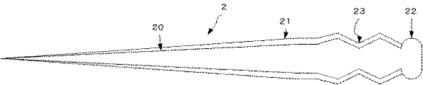
(第1の実施形態)図1は、本発明の第1の実施形態の入力用タッチペンに使用するテーパ繊維2の模式図である。テーパ繊維2自体は、同図に示す通りの先細り形状の繊維である。そして、本発明の入力用タッチペンに使用するテーパ繊維は、その表面を導電性被膜21で覆われる。
Hereinafter, an input touch pen according to an embodiment of the present invention will be described with reference to the drawings.
(First Embodiment) FIG. 1 is a schematic view of a
このテーパ繊維2の後方、後端基部の直ぐ前方には導通のための接触部23が設けられ、入力ペンの本体軸1側の接続部12と接触導通する。この接触部23は、本体軸1側の接続部12での摩擦抵抗を大きくするために繊維表面に凹凸を形成させたり、捲縮をさせたりしてもよい。また、このテーパ繊維2の後端基部には鍔状の被係止部22を設け、本体軸1からの抜け止めとしてもよいものである。この被係止部22は、前記した接触部23を設けた場合、導電性被膜21で覆う必要は無く、繊維の基材が露出する状態でもよい。
言うまでもないが、被係止部22を導電性被膜21で覆えば、この部分でも導通することが可能となる。
A
Needless to say, if the locked
図2に示す通り、本体軸1は手指に接触する軸外周部に導電性を有する部材11で被覆されている。前記した通り、この本体軸1は導電性材料のみから構成することも出来る。ここでは、本体軸1の接続部12とテーパ繊維2の接触部23とが、接触・導通しており、テーパ繊維2後端の被係止部22は導電性被膜21で覆われていない。尖端部テーパ繊維2の導電性被膜21から、接触部23、接続部12を通じて、本体軸1外周部まで、導電性材料で繋がっている構成となっている。本実施例において、テーパ繊維2から軸本体1外周部までの電気抵抗の測定を行ったが、相当に高い値で測定値が変動し、明確な値を測定値として示すことが出来ないが、入力動作に対する反応は全く問題が無く正確な入力を行うことができた。
As shown in FIG. 2, the
このように構成した入力用タッチペンは、入力尖端部が唯一本のテーパ繊維2であり、外観、使用感ともに極細の毛筆に酷似しており、細かい毛筆類似の入力が可能となる。使用が進み、テーパ繊維2が摩耗した場合には、このテーパ繊維2を除去して、新たに導電性被膜21を被覆したテーパ繊維2´を装着することができる。この時、本体軸1の接続部12が洗濯バサミ状に構成されていれば、テーパ繊維2の交換はより容易である。ところで、テーパ繊維2上の導電性被膜21のみが摩耗によって無くなってしまった場合には、前記した方法により導電性被膜21を再建することにより、再度入力用タッチペンとして使用可能となる。
The input touch pen configured as described above has only one tapered
ところで、テーパ繊維を交換可能としない場合には、導電性被膜21で覆った被係止部22、あるいは、接触部23において、接続部12との導通を確実にするために、導電性材料を含む接着剤を用いて、被係止部22、あるいは、接続部23と、接続部12とを接着することも出来る。
By the way, in the case where the taper fiber is not replaceable, in order to ensure conduction with the connecting
(第2の実施形態)第2の実施形態は、軸体を導電性のない軸体1’としたこと以外は第1の実施形態と同様にして構成した。この実施形態においても、テーパ繊維2が着脱可能となっているため、使用者が「筆記抵抗」や「入力感」が気に入らない場合には、このテーパ繊維2を交換することで、気に入った「筆記抵抗」や「入力感」とすることができる。本実施例において、テーパ繊維2から導電性のない軸体1’までの電気抵抗を測定したが、測定器の上限(10MΩ)を超えて測定不能であった。しかし問題なく正確な入力を行うことができた。
(Second Embodiment) The second embodiment is configured in the same manner as the first embodiment except that the shaft body is a non-conductive shaft body 1 '. Also in this embodiment, since the
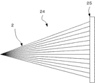
(第3の実施形態)次に、図3を参照しながら、テーパ繊維2を収束させた第2の実施形態に係る繊維束体の入力尖端について説明する。ここで収束されるテーパ繊維2一本一本は、前記したような第1の実施形態で使用した導電性被膜21を被覆したテーパ繊維2と同じものである。ここでは、基材20が熱可塑性樹脂のテーパ繊維2の基部を加熱によって繊維同士を融着させ、その融着部を後方から加熱しながら押し広げて被係止部25を形成している。
(Third Embodiment) Next, the input tip of the fiber bundle according to the second embodiment in which the tapered
ここでは、導電性被膜21がテーパ繊維2の後端まで施されていても、この熱融着の工程によって破壊されてしまうので、改めて前記した方法によって導電性被膜21を形成させ、本体軸1側との導通を確保することも可能である。また、この図3では、被係止部に導電性被膜21を設けて導通を確保する形態を採っているが、より確実に本体軸1側との導通を確保するために、この被係止部25の何れかの箇所に端子部を設けることもできる。この端子部を繊維束24の入力尖端被係止部25に設けた場合は、当然ながら、本体軸1側に、この端子部と合致できる位置に接続部を設けることでより固い接続を確保することができる。
Here, even if the conductive coating 21 is applied up to the rear end of the
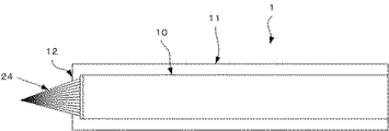
図4に示す通り、第1の実施形態同様、本体軸1は手指に接触する軸外周部に導電性を有する部材11で被覆されている。前記した通り、この本体軸1は導電性材料のみから構成することも出来る。ここでは、本体軸1の接続部12と繊維束の入力尖端被係止部とが、接触・導通しており、繊維束24の入力尖端後端の被係止部25は導電性被膜21で覆われている。繊維束24の入力尖端の導電性被膜21から、接触部23、接続部12を通じて、本体軸1外周部まで、導電性材料で繋がっている構成となっている。本実施例において、繊維束24から軸本体1外周部までの電気抵抗の測定を行ったが、相当に高い値で測定値が変動し、明確な値を測定値として示すことが出来ないが、入力動作に対する反応は全く問題が無く正確な入力を行うことができた。
As shown in FIG. 4, as in the first embodiment, the
このように構成した入力用タッチペンは、入力尖端部がテーパ繊維の繊維束であり、外観、使用感ともに毛筆に酷似しており、毛筆類似の入力が可能となる。使用が進み、テーパ繊維が摩耗した場合には、このテーパ繊維の繊維束24を除去して、新たに導電性被膜21を被覆したテーパ繊維の繊維束24´を装着することができる。ところで、テーパ繊維上の導電性被膜21のみが摩耗によって無くなってしまった場合には、前記した方法により導電性被膜21を再建することにより、再度入力用タッチペンとして使用可能となる。
The input touch pen configured as described above has a fiber bundle of tapered fibers at the input tip, which is very similar to a brush in terms of appearance and usability, and enables input similar to a brush. When the taper fiber wears out as the use proceeds, the
この第3の実施形態においても、繊維束24を交換可能としない場合には、導電性被膜21で覆った被係止部25において、接続部12との導通を確実にするために、導電性材料を含む接着剤を用いて、被係止部25と、接続部12とを接着することも出来る。
Also in the third embodiment, when the
(第4の実施形態)第4の実施形態は、意匠上の理由等で、前記第3の実施形態において、本体軸1を後端が開放された竹製の筆様の形態としたものである(図示せず)。この竹製の軸本体1内部に、前記した通り、ペン先と導通するように、導電性繊維、導電性スポンジ、金属、グラファイト焼結体などの導電体を収納しておくことで、導電体の体積を増大させ、静電容量型座標入力装置または表示一体型静電容量型入力装置の応答性を適宜調整することができる。そして、入力尖端部保護のため、本体軸先方に嵌着するキャップ体を備えてもよい。本実施例において、テーパ繊維2から導電性のない竹製の本体軸1外週部までの電気抵抗を測定したが、測定器の上限(10MΩ)を超えて測定不能であった。しかし問題なく正確な入力を行うことができた。
(Fourth Embodiment) In the fourth embodiment, for the reasons of design, the
(第3の実施形態の変形例)更に、図5を参照しながら、テーパ繊維2を収束させた第2の実施形態の変形例に係る繊維束体の入力尖端について説明する。ここでは、入力尖端を幅広の平筆状に形成させた以外は、前記第2の実施形態と同様である。このように構成した入力用タッチペンは、入力尖端部がテーパ繊維2の繊維束24であり、外観、使用感ともに所謂絵筆に酷似しており、絵筆に類似の入力が可能となる。
(Modified Example of Third Embodiment) Further, an input tip of a fiber bundle according to a modified example of the second embodiment in which the tapered
この他、繊維束体の入力尖端の形状には断面が楕円形の絵筆状のもの、平筆よりも更に幅広の刷毛状のもの等を挙げることが出来る。 In addition, examples of the shape of the input tip of the fiber bundle include a paintbrush having an elliptical cross section and a brush having a wider width than a flat brush.
以上の説明から明らかなように、本発明の静電入力型タッチペンによれば、入力パッドからのアナログ的な入力、即ち、毛筆や絵筆で描いたような、ごく細い描線から筆幅一杯の太い線まで、線幅を変更しながら描くような入力、あるいは、「止め」や「跳ね」などを行った際に、極めて予測不可能かつランダムに「掠れた」描線を得ることが出来る。また、使用により入力尖端部が損耗した場合でも、導電性被膜の再建、あるいは、入力先端部そのものの交換が容易に行える。 As is apparent from the above description, according to the electrostatic input touch pen of the present invention, analog input from the input pad, that is, a very thin stroke drawn with a brush or a paintbrush, to a full stroke width. When a line is drawn while changing the line width, or “stop” or “bounce” is performed, it is possible to obtain a drawn line that is very unpredictable and randomly drawn. Further, even when the input tip is worn out by use, it is possible to easily rebuild the conductive film or replace the input tip itself.
本発明品は、デジタル映像への加筆、加工、あるいは、文字、筆跡および絵画の入力に利用することが出来る。 The product of the present invention can be used for adding and processing digital video, or inputting characters, handwriting, and pictures.
1 本体軸
2 テーパ繊維
10 本体軸基材
11 導電性を有する部材
12 本体軸接続部
20 テーパ繊維基材
21 導電性被膜
22 テーパ繊維被係止部
23 テーパ繊維接触部
24 テーパ繊維の繊維束
25 繊維束被係止部
DESCRIPTION OF
Claims (5)
前記テーパ繊維の表面には導電性樹脂の被覆を持つことを特徴とする入力用タッチペン。 It is an input touch pen with an input tip made of a tapered fiber,
An input touch pen characterized by having a conductive resin coating on a surface of the taper fiber.
Priority Applications (1)
| Application Number | Priority Date | Filing Date | Title |
|---|---|---|---|
| JP2011234486A JP5832236B2 (en) | 2010-10-28 | 2011-10-26 | Capacitive touch pen |
Applications Claiming Priority (3)
| Application Number | Priority Date | Filing Date | Title |
|---|---|---|---|
| JP2010242291 | 2010-10-28 | ||
| JP2010242291 | 2010-10-28 | ||
| JP2011234486A JP5832236B2 (en) | 2010-10-28 | 2011-10-26 | Capacitive touch pen |
Publications (2)
| Publication Number | Publication Date |
|---|---|
| JP2012108894A true JP2012108894A (en) | 2012-06-07 |
| JP5832236B2 JP5832236B2 (en) | 2015-12-16 |
Family
ID=46494398
Family Applications (1)
| Application Number | Title | Priority Date | Filing Date |
|---|---|---|---|
| JP2011234486A Expired - Fee Related JP5832236B2 (en) | 2010-10-28 | 2011-10-26 | Capacitive touch pen |
Country Status (1)
| Country | Link |
|---|---|
| JP (1) | JP5832236B2 (en) |
Cited By (5)
| Publication number | Priority date | Publication date | Assignee | Title |
|---|---|---|---|---|
| JP2013017613A (en) * | 2011-07-11 | 2013-01-31 | Nihon Sanmo Dyeing Co Ltd | Brush fiber, brush using the same, method for manufacturing brush fiber |
| JP2014004280A (en) * | 2012-06-27 | 2014-01-16 | Nippon Sanmou Senshoku Kk | Method of manufacturing bristle neck for brush |
| WO2014092211A1 (en) * | 2012-12-10 | 2014-06-19 | Jung Youngwoo | Antistatic brush hair and capacitive touch pen including same |
| WO2014106918A1 (en) * | 2013-01-07 | 2014-07-10 | 三菱鉛筆株式会社 | Electrically conductive brush pen |
| JP2015079347A (en) * | 2013-10-16 | 2015-04-23 | テイボー株式会社 | Pen tip |
Citations (8)
| Publication number | Priority date | Publication date | Assignee | Title |
|---|---|---|---|---|
| JP2001063268A (en) * | 1999-06-25 | 2001-03-13 | Kuretake Seishiyoudou:Kk | Flock bundle and its manufacture |
| JP2002254017A (en) * | 2001-03-01 | 2002-09-10 | Pilot Ink Co Ltd | Simple applicator |
| JP2004090506A (en) * | 2002-09-02 | 2004-03-25 | Mitsubishi Pencil Co Ltd | Tip fitting structure of applicator |
| JP2008109990A (en) * | 2006-10-30 | 2008-05-15 | Fuji Chemical Kk | Manufacturing method of bristle for cosmetic brush |
| US20080266267A1 (en) * | 2007-04-30 | 2008-10-30 | Chih-Chang Chang | Pen for touch pad of a laptop |
| US20090008162A1 (en) * | 2007-07-03 | 2009-01-08 | Wei-Wen Yang | Input Device of Capacitive Touchpad |
| US20100006350A1 (en) * | 2008-07-11 | 2010-01-14 | Elias John G | Stylus Adapted For Low Resolution Touch Sensor Panels |
| JP2010039610A (en) * | 2008-08-01 | 2010-02-18 | Shin Etsu Polymer Co Ltd | Electrostatic capacity type input pen |
-
2011
- 2011-10-26 JP JP2011234486A patent/JP5832236B2/en not_active Expired - Fee Related
Patent Citations (8)
| Publication number | Priority date | Publication date | Assignee | Title |
|---|---|---|---|---|
| JP2001063268A (en) * | 1999-06-25 | 2001-03-13 | Kuretake Seishiyoudou:Kk | Flock bundle and its manufacture |
| JP2002254017A (en) * | 2001-03-01 | 2002-09-10 | Pilot Ink Co Ltd | Simple applicator |
| JP2004090506A (en) * | 2002-09-02 | 2004-03-25 | Mitsubishi Pencil Co Ltd | Tip fitting structure of applicator |
| JP2008109990A (en) * | 2006-10-30 | 2008-05-15 | Fuji Chemical Kk | Manufacturing method of bristle for cosmetic brush |
| US20080266267A1 (en) * | 2007-04-30 | 2008-10-30 | Chih-Chang Chang | Pen for touch pad of a laptop |
| US20090008162A1 (en) * | 2007-07-03 | 2009-01-08 | Wei-Wen Yang | Input Device of Capacitive Touchpad |
| US20100006350A1 (en) * | 2008-07-11 | 2010-01-14 | Elias John G | Stylus Adapted For Low Resolution Touch Sensor Panels |
| JP2010039610A (en) * | 2008-08-01 | 2010-02-18 | Shin Etsu Polymer Co Ltd | Electrostatic capacity type input pen |
Cited By (7)
| Publication number | Priority date | Publication date | Assignee | Title |
|---|---|---|---|---|
| JP2013017613A (en) * | 2011-07-11 | 2013-01-31 | Nihon Sanmo Dyeing Co Ltd | Brush fiber, brush using the same, method for manufacturing brush fiber |
| JP2014004280A (en) * | 2012-06-27 | 2014-01-16 | Nippon Sanmou Senshoku Kk | Method of manufacturing bristle neck for brush |
| WO2014092211A1 (en) * | 2012-12-10 | 2014-06-19 | Jung Youngwoo | Antistatic brush hair and capacitive touch pen including same |
| WO2014106918A1 (en) * | 2013-01-07 | 2014-07-10 | 三菱鉛筆株式会社 | Electrically conductive brush pen |
| TWI588686B (en) * | 2013-01-07 | 2017-06-21 | Mitsubishi Pencil Company Limited | Conductive pen |
| JP2015079347A (en) * | 2013-10-16 | 2015-04-23 | テイボー株式会社 | Pen tip |
| WO2015056753A1 (en) * | 2013-10-16 | 2015-04-23 | テイボー株式会社 | Pen point |
Also Published As
| Publication number | Publication date |
|---|---|
| JP5832236B2 (en) | 2015-12-16 |
Similar Documents
| Publication | Publication Date | Title |
|---|---|---|
| JP5832236B2 (en) | Capacitive touch pen | |
| JP5946396B2 (en) | Touch pen for input | |
| JP5996101B2 (en) | Input device for touch sensitive capacitive display | |
| JP5832238B2 (en) | Information input pen | |
| JP2012168934A (en) | Pen for information input | |
| JP2014112355A (en) | Touch pen for input, and a manufacturing method for the same | |
| JP5890693B2 (en) | Information input pen | |
| JP5832237B2 (en) | Information input pen | |
| JP5139601B1 (en) | Input device and input pen using the same | |
| JP2015032285A (en) | Stylus pen used for touch panel | |
| JP2016115029A (en) | Handwriting input pen | |
| JP6261900B2 (en) | pencil | |
| JP7241277B2 (en) | Pen tip for touch panel and manufacturing method thereof | |
| JP6098921B2 (en) | Touch panel pen tip | |
| JP6083782B2 (en) | Information input pen | |
| JP5832235B2 (en) | Information input pen | |
| JP2013143014A (en) | Information input pen | |
| JP5944289B2 (en) | Stylus pen and touch panel system | |
| JP2016110187A (en) | Handwriting input pen | |
| JP2012252525A (en) | Information input pen | |
| JP6460624B2 (en) | Nib | |
| JP5382964B1 (en) | Conductive input member for input devices | |
| TWI588686B (en) | Conductive pen | |
| JP6474264B2 (en) | A pencil with a cap consisting of a pencil and a cap |
Legal Events
| Date | Code | Title | Description |
|---|---|---|---|
| A621 | Written request for application examination |
Free format text: JAPANESE INTERMEDIATE CODE: A621 Effective date: 20140924 |
|
| A977 | Report on retrieval |
Free format text: JAPANESE INTERMEDIATE CODE: A971007 Effective date: 20150731 |
|
| A131 | Notification of reasons for refusal |
Free format text: JAPANESE INTERMEDIATE CODE: A131 Effective date: 20150806 |
|
| A521 | Request for written amendment filed |
Free format text: JAPANESE INTERMEDIATE CODE: A523 Effective date: 20151001 |
|
| TRDD | Decision of grant or rejection written | ||
| A01 | Written decision to grant a patent or to grant a registration (utility model) |
Free format text: JAPANESE INTERMEDIATE CODE: A01 Effective date: 20151021 |
|
| A61 | First payment of annual fees (during grant procedure) |
Free format text: JAPANESE INTERMEDIATE CODE: A61 Effective date: 20151027 |
|
| R150 | Certificate of patent or registration of utility model |
Ref document number: 5832236 Country of ref document: JP Free format text: JAPANESE INTERMEDIATE CODE: R150 |
|
| R250 | Receipt of annual fees |
Free format text: JAPANESE INTERMEDIATE CODE: R250 |
|
| LAPS | Cancellation because of no payment of annual fees |