JP2012105908A - Absorptive article - Google Patents

Absorptive article Download PDF

Info

Publication number
JP2012105908A
JP2012105908A JP2010258584A JP2010258584A JP2012105908A JP 2012105908 A JP2012105908 A JP 2012105908A JP 2010258584 A JP2010258584 A JP 2010258584A JP 2010258584 A JP2010258584 A JP 2010258584A JP 2012105908 A JP2012105908 A JP 2012105908A
Authority
JP
Japan
Prior art keywords
wing
main body
side edge
constricted
forming material
Prior art date
Legal status (The legal status is an assumption and is not a legal conclusion. Google has not performed a legal analysis and makes no representation as to the accuracy of the status listed.)
Granted
Application number
JP2010258584A
Other languages
Japanese (ja)
Other versions
JP5685421B2 (en
Inventor
Satoshi Tanaka
聰 田中
Hiroyuki Yokomatsu
弘行 横松
Harumi Tezuka
晴美 手塚
Yuka Hayashi
由佳 林
Shinsuke Nagahara
進介 長原
Current Assignee (The listed assignees may be inaccurate. Google has not performed a legal analysis and makes no representation or warranty as to the accuracy of the list.)
Kao Corp
Original Assignee
Kao Corp
Priority date (The priority date is an assumption and is not a legal conclusion. Google has not performed a legal analysis and makes no representation as to the accuracy of the date listed.)
Filing date
Publication date
Application filed by Kao Corp filed Critical Kao Corp
Priority to JP2010258584A priority Critical patent/JP5685421B2/en
Publication of JP2012105908A publication Critical patent/JP2012105908A/en
Application granted granted Critical
Publication of JP5685421B2 publication Critical patent/JP5685421B2/en
Active legal-status Critical Current
Anticipated expiration legal-status Critical

Links

Images

Landscapes

  • Absorbent Articles And Supports Therefor (AREA)

Abstract

PROBLEM TO BE SOLVED: To provide an absorptive article whose side edges of a body part hardly touch the skin of a user and bent parts of wing parts also hardly touch the skin of the user to improve a feeling of use, when it is attached to the crotch part of underwear and is used.SOLUTION: The absorptive article 1 includes a surface sheet 2, a backside sheet 3, a vertically long body part 5 with an absorptive body 4 arranged between both the sheets, and a pair of wing parts 6, 6 extended from both side edges of the body part 5. The body part 5 includes a constricted part 7 at the position of the wing part 6. The wing part 6 is formed in such a way that a wing part forming material 62 of a separate body is used, one side edge 63 side positioned on the body part 5 of the wing part forming material 62 is fixed to a non-skin facing surface of the backside sheet 3, and the other side edge 64 side is extended more outside than the constricted part 7. The folding line 66 of the wing part 6 formed upon mounting on the underwear is placed between the side edge 512 of the constricted part 7 and the side edge 511 on a position wherein the width of the body part 5 is the largest.

Description

本発明は、生理用ナプキン、パンティライナー(おりものシート)、失禁パッド等の吸収性物品に関し、特にウイング部を有する吸収性物品に関する。   The present invention relates to an absorbent article such as a sanitary napkin, a panty liner (cage sheet), an incontinence pad, and more particularly to an absorbent article having a wing portion.

一般に、ウイング部を有する吸収性物品は、表面シート、裏面シート及びこれら両シート間に配された吸収体を具備する本体部及び該本体部の両側縁から延出する一対のウイング部を有しており、その使用時には、一対のウイング部を、裏面シート側に折り曲げ、折り曲げたウイング部を、ショーツのクロッチ部の非肌対向面等に粘着剤等で固定して使用する。
また、ウイング部に用いるシート材の使用量を低減する観点等から、ウイング部を有する吸収性物品として、表面シートや裏面シート等の原反とは異なる原反から、ウイング部に近い形状のウイング片を形成し、そのウイング片を、表面シートや裏面シート等の本体部の構成材料と接合し、本体部の両側部に固定した吸収性物品が提案されている。
In general, an absorbent article having a wing portion has a main body portion including a top sheet, a back sheet, and an absorbent body disposed between both sheets, and a pair of wing portions extending from both side edges of the main body portion. At the time of use, the pair of wings are bent to the back sheet side, and the bent wings are fixed to the non-skin facing surface of the crotch part of the shorts with an adhesive or the like.
In addition, from the viewpoint of reducing the amount of sheet material used for the wing part, as an absorbent article having a wing part, a wing having a shape close to the wing part from a raw material different from the raw material such as a top sheet and a back sheet. There has been proposed an absorbent article in which a piece is formed, the wing piece is joined to a constituent material of a main body such as a top sheet or a back sheet, and fixed to both sides of the main body.

このような本体部の両側部にウイング片を固定した吸収性物品として、例えば、特許文献1には、吸収コアを有する主本体部分と、該主本体部分の両側縁部それぞれに配された複数の側部被覆要素構成要素とを備え、主本体部分と別体である複数の側部被覆要素構成要素が少なくとも部分的に重複している吸収物品が記載されている。   As an absorbent article in which wing pieces are fixed to both side portions of such a main body portion, for example, Patent Document 1 discloses a plurality of main body portions each having an absorption core and both side edge portions of the main body portion. And a plurality of side covering element components that are separate from the main body portion are described.

しかし、特許文献1に記載の吸収物品は、複数の側部被覆要素構成要素が、主本体部分を構成するトップシートとバックシートとの間に配されているため、特許文献1に記載の吸収物品を下着のクロッチ部に取り付けて使用する際に、側部被覆構成要素がうまく下着の裏面側に折返し固定ができない等の操作性の問題や、トップシートとバックシートとを固定した主本体部分の側縁が、使用者の肌に当たる場合があった。   However, in the absorbent article described in Patent Document 1, a plurality of side covering element components are arranged between the top sheet and the back sheet that constitute the main body portion, and therefore, the absorbent article described in Patent Document 1 When attaching an article to the crotch part of the underwear, the main body part that fixes the top sheet and the back sheet, such as problems of operability such as the side covering components cannot be properly folded back to the back side of the underwear There was a case where the side edge of the touched the user's skin.

また、特許文献2には、吸収性コアを有する主本体部分と、主本体部分の両長手方縁に配され主本体部分を構成するバックシートの下面に配された一対のフラップとを備えた吸収性製品が記載されている。   Further, Patent Document 2 includes a main body portion having an absorbent core, and a pair of flaps disposed on both lower longitudinal edges of the main body portion and disposed on the lower surface of the back sheet constituting the main body portion. Absorbent products are listed.

しかし、特許文献2に記載の吸収性製品は、主本体部分が両長手方縁に括れを有する形状でないため、特許文献2に記載の吸収性製品を下着のクロッチ部に取り付けて使用する際に、主本体部分を構成するトップシートとバックシートとの固定部分である主本体部分の側縁が、やはり使用者の肌に当たる場合があった。また、特許文献2に記載の吸収性製品を下着のクロッチ部に取り付けて使用する際に、フラップの折り曲げ部分が重ねて形成されているため使用者の肌に当たる場合があった。   However, the absorbent product described in Patent Document 2 is not in a shape in which the main body portion is constricted on both longitudinal edges, so when the absorbent product described in Patent Document 2 is attached to the crotch portion of the underwear. The side edge of the main body portion, which is a fixed portion between the top sheet and the back sheet constituting the main body portion, sometimes hits the user's skin. Moreover, when attaching and using the absorptive product of patent document 2 to the crotch part of underwear, since the bending part of the flap was piled up and formed, it might hit a user's skin.

特表平9−501335号公報JP-T 9-501335 特開2001−149410号公報JP 2001-149410 A

従って、本発明の課題は、前述した従来技術が有する欠点を解消し得る吸収性物品を提供することにある。   Therefore, the subject of this invention is providing the absorbent article which can eliminate the fault which the prior art mentioned above has.

本発明は、表面シート、裏面シート及びこれら両シート間に配された吸収体を具備する縦長の本体部、及び該本体部の両側縁から延出する一対のウイング部を有する吸収性物品であって、前記本体部は、前記ウイング部の位置において内方に括れる括れ部を有しており、前記括れ部は、括れた前記表面シートの縁部及び括れた前記裏面シートの縁部が互いにシールされて形成されており、前記吸収体の側縁は、前記括れ部よりも内方に位置しており、前記ウイング部は、前記表面シート及び前記裏面シートとは別体の肌当接面側が不織布であるウイング部形成材を用い、該ウイング部形成材の前記本体部に位置する一側縁側が前記裏面シートの非肌対向面に固定され、他側縁側が前記本体部の前記括れ部より外方に延出するように配されて形成されており、前記吸収性物品を下着に装着する際に形成される前記ウイング部の折り曲げ線が、前記括れ部での側縁と前記本体部の幅が最も広い位置での側縁との間に配される吸収性物品を提供するものである。   The present invention is an absorbent article having a top sheet, a back sheet, and a vertically long main body having an absorbent body disposed between both sheets, and a pair of wings extending from both side edges of the main body. The main body portion has a constricted portion that is bound inward at the position of the wing portion, and the constricted portion includes an edge portion of the constricted top sheet and an edge portion of the constricted back sheet. The side edge of the absorber is located inward of the constricted part, and the wing part is a skin contact surface that is separate from the top sheet and the back sheet. Using a wing part forming material whose side is a non-woven fabric, one side edge side of the wing part forming material located on the main body part is fixed to the non-skin facing surface of the back sheet, and the other side edge side is the constricted part of the main body part Arranged so as to extend outward The fold line of the wing part formed when the absorbent article is attached to the underwear is between the side edge at the constricted part and the side edge at the widest position of the main body part. An absorbent article to be provided is provided.

本発明の吸収性物品によれば、下着のクロッチ部に取り付けて使用する際に、本体部の側縁が使用者の肌に当たり難く、ウイング部の折り曲げ部分も使用者の肌に当たり難く、使用感が向上する。   According to the absorbent article of the present invention, when attached to the crotch part of the undergarment, the side edge of the main body part is less likely to hit the user's skin, and the bent part of the wing part is less likely to hit the user's skin. Will improve.

図1は、本発明の一実施形態である生理用ナプキンを表面シート側から見た平面図である。FIG. 1 is a plan view of a sanitary napkin according to an embodiment of the present invention as viewed from the surface sheet side. 図2は、図1に示す生理用ナプキンを裏面シート側から見た平面図である。FIG. 2 is a plan view of the sanitary napkin shown in FIG. 1 as viewed from the back sheet side. 図3は、図1のY1−Y1線断面図である。3 is a cross-sectional view taken along line Y1-Y1 of FIG. 図4は、図1に示す生理用ナプキンを下着のクロッチ部に取り付けた使用状態の断面図である。FIG. 4 is a sectional view of the sanitary napkin shown in FIG. 図5は、図1に示す生理用ナプキンを下着のクロッチ部に取り付けた使用状態において、ウイング部の折り曲げ線と本体部の側縁との位置関係を説明するための図である。FIG. 5 is a view for explaining the positional relationship between the fold line of the wing part and the side edge of the main body part in a use state where the sanitary napkin shown in FIG. 1 is attached to the crotch part of the undergarment. 図6は、本発明の他の実施形態である生理用ナプキンを表面シート側から見た平面図である(図1相当図)。FIG. 6 is a plan view of a sanitary napkin according to another embodiment of the present invention as seen from the top sheet side (corresponding to FIG. 1). 図7は、図6に示す生理用ナプキンを裏面シート側から見た平面図である(図2相当図)。FIG. 7 is a plan view of the sanitary napkin shown in FIG. 6 as viewed from the back sheet side (corresponding to FIG. 2). 図8は、図6のY2−Y2線断面図である(図3相当図)。8 is a cross-sectional view taken along line Y2-Y2 of FIG. 6 (corresponding to FIG. 3). 図9は、図6に示す生理用ナプキンを下着のクロッチ部に取り付けた使用状態の断面図である(図4相当図)。9 is a cross-sectional view of the sanitary napkin shown in FIG. 6 attached to the crotch portion of the undergarment (corresponding to FIG. 4). 図10は、本発明の他の実施形態である生理用ナプキンを表面シート側から見た平面図である(図1相当図)。FIG. 10 is a plan view of a sanitary napkin according to another embodiment of the present invention as viewed from the surface sheet side (corresponding to FIG. 1). 図11は、図10に示す生理用ナプキンを裏面シート側から見た平面図である(図2相当図)。FIG. 11 is a plan view of the sanitary napkin shown in FIG. 10 as seen from the back sheet side (corresponding to FIG. 2). 図12は、図10のY3−Y3線断面図である(図3相当図)。12 is a cross-sectional view taken along line Y3-Y3 of FIG. 10 (corresponding to FIG. 3). 図13は、図10に示す生理用ナプキンを下着のクロッチ部に取り付けた使用状態の断面図である(図4相当図)。FIG. 13 is a sectional view of the sanitary napkin shown in FIG. 10 attached to the crotch portion of the undergarment (corresponding to FIG. 4).

以下本発明をその好ましい実施形態に基づき図面を参照しながら説明する。
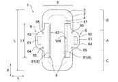
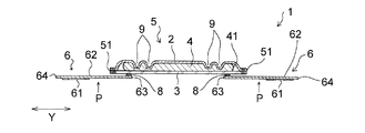
本発明の実施形態である生理用ナプキン1(以下、ナプキン1ともいう)は、図1〜図3に示すように、表面シート2、裏面シート3及びこれら両シート2,3間に配された吸収体4を具備する縦長の本体部5及び該本体部5の両側縁から延出する一対のウイング部6,6を有する。
本明細書において、「肌対向面」とは、本体部5などの各部材の表裏両面のうち、着用時に着用者の肌側に配される面であり、「非肌対向面」とは、本体部5などの各部材の表裏両面のうち、着用時に着用者の肌側とは反対側に向けられる面である。
The present invention will be described below based on preferred embodiments with reference to the drawings.
A sanitary napkin 1 (hereinafter also referred to as a napkin 1) according to an embodiment of the present invention is disposed between a top sheet 2, a back sheet 3, and both the sheets 2, 3, as shown in FIGS. It has a vertically long main body portion 5 including the absorber 4 and a pair of wing portions 6 and 6 extending from both side edges of the main body portion 5.
In the present specification, the “skin facing surface” is a surface arranged on the skin side of the wearer when wearing among the front and back surfaces of each member such as the main body portion 5, and the “non-skin facing surface” Among the front and back surfaces of each member such as the main body 5, the surface is directed to the side opposite to the wearer's skin when worn.

本体部5は、図1中X方向に長い形状を有し、その裏面には、該本体部5を、ショーツのクロッチ部10の肌対向面(着用者の肌側に向けられる面)に固定するための本体粘着部(図示せず)が形成されており、ウイング部6の裏面には、図2〜図4に示すように、各ウイング部6を、ショーツのクロッチ部10(図4参照)の非肌対向面(着用者の肌側とは反対側に向けられる面)に固定するためのウイング部粘着部61が形成されている。クロッチ部10の非肌対向面には、上層及び下層を有する二重構造のクロッチ部の下層側の面も含まれる。   The main body 5 has a shape that is long in the X direction in FIG. 1, and the main body 5 is fixed to the skin facing surface of the crotch portion 10 of the shorts (the surface facing the wearer's skin) on the back surface. A main body adhesive portion (not shown) is formed, and on the back surface of the wing portion 6, as shown in FIGS. 2 to 4, each wing portion 6 is connected to a crotch portion 10 of shorts (see FIG. 4). ) Non-skin facing surface (surface facing away from the wearer's skin side) is formed. The non-skin facing surface of the crotch unit 10 includes a lower layer side surface of a dual-structure crotch unit having an upper layer and a lower layer.

本体部5は、図1に示すように、ウイング部6の位置において内方に括れる括れ部7を有している。本体部5は、図1に示すように、ウイング部6,6の位置する領域である中央部A、ナプキン1の着用時に中央部Aより着用者の腹側に配される前方部B、及びナプキン1の着用時に中央部Aよりも着用者の背中側に配される後方部Cを有している。ここで、ウイング部6の位置とは、ウイング部6,6の位置する領域である中央部Aを意味しており、本体部5の括れ部7は、中央部Aに形成されている。ナプキン1の着用時には、通常、本体部5の中央部Aが、着用者の液排出部(膣口等)に対向配置される。   As shown in FIG. 1, the main body 5 has a constricted portion 7 that is bound inward at the position of the wing portion 6. As shown in FIG. 1, the main body 5 includes a central part A that is a region where the wing parts 6 and 6 are located, a front part B that is arranged on the stomach side of the wearer from the central part A when the napkin 1 is worn, and When the napkin 1 is worn, it has a rear portion C arranged on the back side of the wearer rather than the central portion A. Here, the position of the wing part 6 means the central part A, which is an area where the wing parts 6 and 6 are located, and the constricted part 7 of the main body part 5 is formed in the central part A. When the napkin 1 is worn, the central part A of the main body part 5 is usually arranged opposite to the wearer's liquid discharge part (such as the vaginal opening).

本体部5は、図2に示すように、液透過性の表面シート2、液不透過性又は撥水性の裏面シート3及びこれら両シート間に配された液保持性の吸収体4を具備する。
表面シート2、裏面シート3及び吸収体4は、何れも、本体部5の長手方向(X方向)に長い縦長の形状を有しており、ナプキン1においては、表面シート2と裏面シート3とが同形同大に形成されている。尚、各図中のY方向は、長手方向(X方向)に直交する方向であり、本体部5の幅方向でもある。
As shown in FIG. 2, the main body 5 includes a liquid-permeable top sheet 2, a liquid-impermeable or water-repellent back sheet 3, and a liquid-retaining absorbent 4 disposed between the two sheets. .
Each of the top sheet 2, the back sheet 3, and the absorber 4 has a vertically long shape in the longitudinal direction (X direction) of the main body 5. In the napkin 1, the top sheet 2, the back sheet 3, Are formed in the same shape and size. In addition, the Y direction in each figure is a direction orthogonal to the longitudinal direction (X direction), and is also the width direction of the main body 5.

表面シート2は、図1に示すように、本体部5の中央部A、前方部B及び後方部Cそれぞれにおいて、本体部5の輪郭と一致する輪郭を有している。即ち、表面シート2は、中央部Aにおいて内方に括れる括れ部7を有している。   As shown in FIG. 1, the topsheet 2 has a contour that matches the contour of the main body portion 5 at each of the central portion A, the front portion B, and the rear portion C of the main body portion 5. That is, the topsheet 2 has a constricted portion 7 that is bound inward at the central portion A.

裏面シート3も、表面シート2と同様に、図1に示すように、本体部5の中央部A、前方部B及び後方部Cそれぞれにおいて、本体部5の輪郭と一致する輪郭を有している。即ち、裏面シート3も、中央部Aにおいて内方に括れる括れ部7を有している。   Similarly to the top sheet 2, the back sheet 3 also has a contour that matches the contour of the main body 5 at each of the central part A, the front part B, and the rear part C of the main body 5, as shown in FIG. 1. Yes. That is, the back sheet 3 also has a constricted portion 7 that is bound inward at the central portion A.

本体部5の括れ部7は、図1に示すように、括れた表面シート2の縁部及び括れた裏面シート3の縁部が互いにシールされて形成されている。具体的には、本体部5が、本体部5の輪郭と一致する輪郭の表面シート2及び裏面シート3を、それぞれの縁部全周に亘って互いにシールすることにより形成されると同時に、本体部5の括れ部7が、表面シート2の括れ部と裏面シート3の括れ部とのシールにより形成される。   As shown in FIG. 1, the constricted portion 7 of the main body 5 is formed by sealing the edge of the constricted topsheet 2 and the edge of the constricted backsheet 3 together. Specifically, the main body 5 is formed by sealing the top sheet 2 and the back sheet 3 having contours that coincide with the contour of the main body 5 over the entire circumference of each edge, and at the same time, The constricted part 7 of the part 5 is formed by a seal between the constricted part of the top sheet 2 and the constricted part of the back sheet 3.

ナプキン1においては、図1に示すように、表面シート2と裏面シート3とが、表面シート2の周縁部及び裏面シート3の周縁部それぞれに沿って、熱エンボス加工によって接合されており、ナプキン1の周縁部に周縁シール部11を形成している。
尚、ナプキン1においては、周縁シール部11が熱エンボス加工により形成されているが、超音波シールにより形成されていてもよく、ホットメルト等の接着剤等により形成されていてもよい。周縁シール部11の柔軟性、シール強度及び極端に弱い部分が形成されないシール部分の強度の安定性の観点から、接着剤と熱エンボス加工を併用して形成されていることが好ましい。
In the napkin 1, as shown in FIG. 1, the top sheet 2 and the back sheet 3 are joined by hot embossing along the peripheral edge of the top sheet 2 and the peripheral edge of the back sheet 3. A peripheral seal portion 11 is formed on the peripheral portion of 1.
In the napkin 1, the peripheral seal portion 11 is formed by hot embossing, but may be formed by ultrasonic sealing or may be formed by an adhesive such as hot melt. From the viewpoint of the flexibility of the peripheral seal part 11, the seal strength, and the stability of the strength of the seal part where an extremely weak part is not formed, it is preferable that the peripheral seal part 11 is formed using an adhesive and hot embossing in combination.

吸収体4の側縁41は、図1に示すように、括れ部7よりも内方に位置している。具体的には、吸収体4は、図1に示すように、本体部5の長手方向(X方向)に沿って延びる両側縁41,41を有し、本体部5の前方部B及び後方部Cそれぞれにおける吸収体4の前後端は、ナプキン1及び本体部5の前後端よりやや内側に位置して湾曲形状を有しており、本体部5の中央部Aにおける吸収体4の側縁41は、本体部5の括れ部7よりもY方向内方に位置している。   As shown in FIG. 1, the side edge 41 of the absorber 4 is located inward of the constricted portion 7. Specifically, as shown in FIG. 1, the absorbent body 4 has both side edges 41, 41 extending along the longitudinal direction (X direction) of the main body portion 5, and the front portion B and the rear portion of the main body portion 5. The front and rear ends of the absorbent body 4 in each of C have a curved shape located slightly inside the front and rear ends of the napkin 1 and the main body portion 5, and the side edges 41 of the absorbent body 4 in the central portion A of the main body portion 5. Is located inward in the Y direction relative to the constricted part 7 of the main body part 5.

ナプキン1においては、図1に示すように、ウイング部6の位置する領域(中央部A)に、表面シート2と吸収体4とを熱エンボス加工により一体的に圧縮して形成された2重の防漏溝9を備えている。2重の防漏溝9それぞれは、図1に示すように、幅方向外方に凸状に形成されている。2重の防漏溝9によって、図2に示すように、吸収体4に、左右の防漏溝9間に挟まれた厚みの厚い部分と、その両側に位置する厚みの薄い部分とが形成されている。この厚みの薄い部分は、厚みの厚い部分に比べて、吸収体4の密度が高くなっており、剛性も高くなっている。その為、吸収体4中の液(経血等)が、吸収体4の側縁41から流れ出しにくくなっている。   In the napkin 1, as shown in FIG. 1, a double layer formed by integrally compressing the topsheet 2 and the absorbent body 4 by hot embossing in a region (center A) where the wing portion 6 is located. The leakage prevention groove 9 is provided. Each of the double leak-proof grooves 9 is formed in a convex shape outward in the width direction, as shown in FIG. As shown in FIG. 2, the double leak-proof groove 9 forms a thick portion sandwiched between the left and right leak-proof grooves 9 and thin portions located on both sides of the absorber 4. Has been. In the thin portion, the density of the absorber 4 is higher and the rigidity is higher than that in the thick portion. Therefore, the liquid (such as menstrual blood) in the absorber 4 is difficult to flow out from the side edge 41 of the absorber 4.

本体部5は、長手方向(X方向)に延びる両側縁51,51を有しており、本体部5の幅が最も広い位置における両側縁511,511どうしの間の距離W1が、70〜120mmであることが好ましく、80〜110mmであることが更に好ましい。
本体部5は、本体部5の幅が最も狭い位置、即ち、括れ部7における両側縁512,512どうしの間の距離W2が、40〜90mmであることが好ましく、50〜80mmであることが更に好ましい。
本体部5の両側縁511,511どうしの間の距離W1に対する括れ部7における両側縁512,512どうしの間の距離W2(W2/W1)は、0.3〜0.9であることが好ましく、装着感の高さ(違和感のなさ)及びナプキン1のヨレの少なさの観点から、0.4〜0.8であることが更に好ましい。
括れ部7の面積(本体部5の前方部Bの側縁51における本体部5の幅が最も広い位置、及び本体部5の後方部Cの側縁51における本体部5の幅が最も広い位置を結ぶ直線と、本体部5の側縁51とで囲まれた部分の面積)は、300〜1500mm2であることが好ましく、上記と同じ観点から、400〜1200mm2であることが更に好ましい。
本体部5の括れ部7における側縁512と本体部5の中央部Aにおける吸収体4の側縁41との間隔W3は、3〜20mmであることが好ましく、ウイング操作性、特に下着への折返し易さの観点から、5〜15mmであることが更に好ましい。
尚、本体部5の長手方向(X方向)の長さは、150〜400mmである。
The main body 5 has side edges 51, 51 extending in the longitudinal direction (X direction), and the distance W1 between the side edges 511, 511 at the position where the width of the main body 5 is the widest is 70 to 120 mm. It is preferable that it is 80-110 mm.
In the main body part 5, the position where the width of the main body part 5 is the narrowest, that is, the distance W2 between the side edges 512 and 512 in the constricted part 7 is preferably 40 to 90 mm, and preferably 50 to 80 mm. Further preferred.
The distance W2 (W2 / W1) between the side edges 512 and 512 in the constricted portion 7 with respect to the distance W1 between the side edges 511 and 511 of the main body 5 is preferably 0.3 to 0.9. From the viewpoints of height of wearing feeling (no discomfort) and little deflection of the napkin 1, it is more preferably 0.4 to 0.8.
Area of the narrow portion 7 (a position where the width of the main body 5 is widest at the side edge 51 of the front part B of the main body 5 and a position where the width of the main body 5 is widest at the side edge 51 of the rear part C of the main body 5 a straight line connecting the area of the portion surrounded by the side edge 51 of the main body portion 5) is preferably 300~1500Mm 2, from the same viewpoint as above, it is more preferably 400~1200mm 2.
The interval W3 between the side edge 512 in the constricted part 7 of the main body part 5 and the side edge 41 of the absorbent body 4 in the central part A of the main body part 5 is preferably 3 to 20 mm. From the viewpoint of ease of folding, it is more preferably 5 to 15 mm.
In addition, the length of the longitudinal direction (X direction) of the main-body part 5 is 150-400 mm.

ナプキン1における一対のウイング部6は、図2,図3に示すように、表面シート2及び裏面シート3とは別体の一対のウイング部形成材62を用い、それぞれ、本体部5に位置する一側縁63側が、裏面シート3の非肌対向面に固定され、他側縁64側が、本体部5の括れ部7より外方(X方向の外方)に延出するように配されて形成されている。
より詳細に説明すると、本実施形態のウイング部形成材62は、図2,図3に示すように、一側縁63が、本体部5の長手方向(X方向)に沿って延びる直線状をなしており、本体部5の幅方向外方側に配される他側縁(外側縁)64が、ウイング部6の輪郭に一致する形状を有している。ウイング部形成材62の可撓部分の一側縁63は、ナプキン1においては、吸収体4の側縁41よりもY方向内方に位置し、2重の防漏溝9におけるY方向外方側の防漏溝9よりも、Y方向外方に位置している。このように、一側縁63は、ナプキン1においては、外方側の防漏溝9と吸収体4の側縁41との間に配されているが、吸収体4の側縁41よりも外方であってもよく、2重の防漏溝9の間に配されていてもよく、ナプキン1の装着時(使用時)における違和感低減と動きへの追従性の観点から、Y方向外方側の防漏溝9と吸収体4の側縁41との間に配されていることが好ましい。ウイング部形成材62は、本実施形態においては、図2に示すように、一側縁63側のX方向の長さL1が、ナプキン1のX方向の長さLに比して短く、ナプキン1の長さLに対して、30〜80%程度であることが好ましい。
As shown in FIGS. 2 and 3, the pair of wing parts 6 in the napkin 1 uses a pair of wing part forming materials 62 that are separate from the top sheet 2 and the back sheet 3, and are respectively positioned on the main body part 5. One side edge 63 side is fixed to the non-skin facing surface of the back sheet 3, and the other side edge 64 side is arranged to extend outward (outward in the X direction) from the constricted part 7 of the main body part 5. Is formed.
More specifically, as shown in FIGS. 2 and 3, the wing part forming material 62 of the present embodiment has a linear shape in which one side edge 63 extends along the longitudinal direction (X direction) of the main body part 5. The other side edge (outer edge) 64 disposed on the outer side in the width direction of the main body part 5 has a shape that matches the contour of the wing part 6. One side edge 63 of the flexible portion of the wing portion forming material 62 is positioned inward in the Y direction with respect to the side edge 41 of the absorbent body 4 in the napkin 1, and is outward in the Y direction in the double leak-proof groove 9. It is located outward in the Y direction with respect to the side leakage prevention groove 9. As described above, in the napkin 1, the one side edge 63 is disposed between the outer leakage preventing groove 9 and the side edge 41 of the absorber 4, but is more than the side edge 41 of the absorber 4. It may be on the outside or may be arranged between the double leak-proof grooves 9. From the viewpoint of reducing a sense of incongruity when the napkin 1 is attached (in use) and following the movement, it is outside the Y direction. It is preferable to be disposed between the side leakage preventing groove 9 and the side edge 41 of the absorber 4. In the present embodiment, as shown in FIG. 2, the wing portion forming material 62 has a length L1 in the X direction on the side edge 63 side shorter than the length L in the X direction of the napkin 1. The length L is preferably about 30 to 80%.

裏面シート3とウイング部形成材62との固定態様について、以下、説明する。
図2に示すように、ウイング部形成材62の本体部5に位置する一側縁63側が、裏面シート3の非肌対向面に固定されている。ナプキン1においては、本体部5の長手方向(X方向)の側部に、ウイング部形成材62と裏面シート3とがホットメルト型接着剤81を介して連続的に接合された帯状接合部8が、本体部5の長手方向(X方向)に延びて形成されている。
Hereinafter, a fixing mode between the back sheet 3 and the wing portion forming material 62 will be described.
As shown in FIG. 2, the side edge 63 side of the wing part forming material 62 located on the main body part 5 is fixed to the non-skin facing surface of the back sheet 3. In the napkin 1, a band-shaped joint portion 8 in which the wing portion forming material 62 and the back sheet 3 are continuously joined to the side portion in the longitudinal direction (X direction) of the main body portion 5 via a hot melt adhesive 81. However, it extends in the longitudinal direction (X direction) of the main body 5.

ウイング部形成材62と裏面シート3との固定により形成される帯状接合部8は、吸収体4と重なっている。詳述すると、上述したように、ウイング部形成材62の一側縁63が、吸収体4の側縁41よりもY方向内方に位置し、2重の防漏溝9におけるY方向外方側の防漏溝9よりも、Y方向外方に位置しており、このように配されたウイング部形成材62と裏面シート3との固定により形成される帯状接合部8は、図3に示すように、ナプキン1においては、2重の防漏溝9におけるY方向外方側の防漏溝9と吸収体4の側縁41との間に配され、吸収体4と重なっている。尚、ナプキン1においては、帯状接合部8が、Y方向外方側の防漏溝9と吸収体4の側縁41との間に配されて吸収体4と重なっているが、吸収体4の側縁41に跨るように吸収体4と重なっていて(外湾曲溝の効果を高めるよう)二重の防漏溝9よりY方向外方の吸収体4のヨレを抑制されていてもよく、Y方向外方側の防漏溝9よりも内側に配されて吸収体4と重なっていて二重の防漏溝9の平面安定性効果をより高めていてもよく、(外湾曲溝の効果を高める)二重の防漏溝9よりY方向外方の吸収体4のヨレ抑制の観点から、二重の防漏溝9と吸収体4の側縁41との間に配されて固定されていることが好ましい。なお、実施形態1における固定部分の外側端部が前述したウイング部形成材62の可撓部分の一側縁63である。   The band-shaped joint portion 8 formed by fixing the wing portion forming material 62 and the back sheet 3 overlaps the absorber 4. More specifically, as described above, one side edge 63 of the wing portion forming material 62 is positioned inward in the Y direction with respect to the side edge 41 of the absorber 4, and the Y direction outward in the double leak-proof groove 9. The band-shaped joint 8 formed by fixing the wing portion forming material 62 and the back sheet 3, which is located outside the leakage prevention groove 9 on the side in the Y direction, is shown in FIG. As shown, in the napkin 1, the double leakage preventing groove 9 is disposed between the leakage preventing groove 9 on the outer side in the Y direction and the side edge 41 of the absorbent body 4, and overlaps the absorbent body 4. In the napkin 1, the band-shaped joint 8 is arranged between the leakage preventing groove 9 on the outer side in the Y direction and the side edge 41 of the absorber 4 and overlaps the absorber 4. It overlaps with the absorber 4 so as to straddle the side edge 41 (in order to enhance the effect of the outer curved groove), and the twist of the absorber 4 outward in the Y direction from the double leakage prevention groove 9 may be suppressed. In addition, it may be arranged inside the leakage prevention groove 9 on the outer side in the Y direction so as to overlap the absorber 4 and further enhance the planar stability effect of the double leakage prevention groove 9 (the outer curved groove From the viewpoint of suppressing the twist of the absorber 4 outward in the Y direction from the double leak-proof groove 9, it is arranged between the double leak-proof groove 9 and the side edge 41 of the absorber 4 and fixed. It is preferable that In addition, the outer side edge part of the fixed part in Embodiment 1 is the one side edge 63 of the flexible part of the wing part forming material 62 mentioned above.

ナプキン1においては、図2に示すように、ウイング部形成材62と裏面シート3とがホットメルト型接着剤81を介して連続的に接合された帯状接合部8が、本体部5の両側部それぞれに、本体部5の長手方向に沿って連続的に延び、ウイング部6の一側縁63側の全長(X方向の全長)に亘って形成されている。   In the napkin 1, as shown in FIG. 2, the band-shaped joint portions 8 in which the wing portion forming material 62 and the back sheet 3 are continuously joined via the hot-melt adhesive 81 are formed on both side portions of the main body portion 5. Each of them extends continuously along the longitudinal direction of the main body portion 5 and is formed over the entire length (the total length in the X direction) on the one side edge 63 side of the wing portion 6.

主として装着時の幅方向(Y方向)伸長に対するウイング部6の脱落防止の観点から、帯状接合部8を形成するホットメルト型接着剤81の幅W4(図2参照)は、1mm以上であることが好ましく、より好ましくは2mm以上、更に好ましくは3mm以上である。他方、ナプキン1の使用時の追従性の観点から、ホットメルト型接着剤81の前記幅W4は、10mm以下であることが好ましく、より好ましくは7mm以下である。   The width W4 (see FIG. 2) of the hot-melt adhesive 81 that forms the band-shaped joint portion 8 is 1 mm or more mainly from the viewpoint of preventing the wing portion 6 from falling off with respect to expansion in the width direction (Y direction) during mounting. Is more preferably 2 mm or more, and still more preferably 3 mm or more. On the other hand, from the viewpoint of followability when the napkin 1 is used, the width W4 of the hot melt adhesive 81 is preferably 10 mm or less, and more preferably 7 mm or less.

また、装着時及び使用時のウイング部6の脱落防止の観点から、帯状接合部8を形成するホットメルト型接着剤81の塗工坪量は、15g/m2であることが好ましく、より好ましくは20g/m2以上、更に好ましくは25g/m2以上である。他方、使用時の違和感(粘着材による硬さ)低減の観点から、ホットメルト型接着剤81の塗工坪量は、150g/m2以下であることが好ましく、より好ましくは120g/m2以下である。 In addition, from the viewpoint of preventing the wing portion 6 from falling off during mounting and use, the coating basis weight of the hot-melt adhesive 81 that forms the band-shaped joint portion 8 is preferably 15 g / m 2 , more preferably. Is 20 g / m 2 or more, more preferably 25 g / m 2 or more. On the other hand, the coating basis weight of the hot-melt adhesive 81 is preferably 150 g / m 2 or less, more preferably 120 g / m 2 or less, from the viewpoint of reducing a sense of incongruity during use (hardness due to the adhesive). It is.

本実施形態のウイング部形成材62は、括れ部7での側縁512と本体部5の幅が最も広い位置での側縁511との間に、折り曲げ誘導手段を備えている。この折り曲げ誘導手段によりウイング部6に折り曲げ線66が形成される。
ナプキン1の折り曲げ誘導手段について、以下に記載する。
ウイング部形成材62は、図1,図2に示すように、括れ部7での側縁512と本体部5の幅が最も広い位置での側縁511との間に、長手方向(X方向)に延びるスリットの形成されたスリット部分65を有する。以下、詳述すると、スリット部分65は、ナプキン1においては、括れ部7での側縁512と本体部5の側縁511との間であって、且つウイング部6の根本付近に一対形成されている。更に詳述すると、括れ部7での側縁512と本体部5の側縁511との間であって、且つ本体部5の側縁51とウイング部形成材62の他側縁64とが交差する位置の近傍に形成されている。このように形成された一対のスリット部分65は、Y方向に延びるウイング部形成材62の中心線CLに対して対称に形成されている。各スリット部分65は、長手方向(X方向)に延びる複数のスリットをウイング部形成材62に設けることにより形成されている。スリットは、1〜10個設けられていることが好ましく、ナプキン1においては、各スリット部分65に、4個形成されている。スリット部分65を形成するスリットは、ナプキン1においては、X方向に水平に形成されているが、長手方向(X方向)に延びていればよく、例えば傾斜を付けて形成されていてもよい。
The wing portion forming material 62 of the present embodiment includes a folding guide means between the side edge 512 at the constricted portion 7 and the side edge 511 at the position where the width of the main body portion 5 is the widest. A folding line 66 is formed in the wing portion 6 by the folding guide means.
The means for guiding the folding of the napkin 1 will be described below.
As shown in FIGS. 1 and 2, the wing part forming material 62 has a longitudinal direction (X direction) between a side edge 512 in the constricted part 7 and a side edge 511 in the position where the width of the main body part 5 is the widest. ) To have a slit portion 65 formed with a slit. More specifically, in the napkin 1, a pair of slit portions 65 are formed between the side edge 512 of the constricted portion 7 and the side edge 511 of the main body portion 5 and in the vicinity of the root of the wing portion 6. ing. More specifically, it is between the side edge 512 of the constricted part 7 and the side edge 511 of the main body part 5, and the side edge 51 of the main body part 5 and the other side edge 64 of the wing part forming material 62 intersect. It is formed in the vicinity of the position. The pair of slit portions 65 formed in this way is formed symmetrically with respect to the center line CL of the wing portion forming material 62 extending in the Y direction. Each slit portion 65 is formed by providing a plurality of slits extending in the longitudinal direction (X direction) in the wing portion forming material 62. It is preferable that 1 to 10 slits are provided. In the napkin 1, four slits 65 are formed in each slit portion 65. The slit forming the slit portion 65 is formed horizontally in the X direction in the napkin 1, but may be formed in an inclined manner as long as it extends in the longitudinal direction (X direction).

上述のように構成されたナプキン1は、図4のようにショーツ等の下着に装着する際に形成されるウイング部6の折り曲げ線66が、図5に示すように、括れ部7での側縁512と本体部5の幅が最も広い位置での側縁511との間に配される。ナプキン1においては、特に、ウイング部6の根本付近に一対のスリット部分65を有している為、スリット部がウイング折り曲げ起点となり、折り曲げ線66が形成される。さらに、スリットが開閉し、ショーツ等の下着に装着する際に折り曲げ線66の位置を調整することができる。   In the napkin 1 configured as described above, the fold line 66 of the wing portion 6 formed when being attached to an underwear such as shorts as shown in FIG. 4 has a side at the constricted portion 7 as shown in FIG. It arrange | positions between the edge 512 and the side edge 511 in the position where the width | variety of the main-body part 5 is the widest. In particular, since the napkin 1 has a pair of slit portions 65 in the vicinity of the root of the wing portion 6, the slit portion serves as a wing folding start point, and a folding line 66 is formed. Furthermore, the slit opens and closes, and the position of the fold line 66 can be adjusted when the garment is attached to an underwear such as shorts.

本発明の第2実施形態である生理用ナプキン1B(以下、「ナプキン1B」ともいう)の折り曲げ誘導手段について、以下に記載する。
尚、ナプキン1Bは、特に説明しない点はナプキン1と同様であり、ナプキン1の説明が適宜適用される。図6〜図9には、ナプキン1の構成要素等と同様の構成要素等に同一の符号を付してある。
The bending induction means of the sanitary napkin 1B (hereinafter also referred to as “napkin 1B”) according to the second embodiment of the present invention will be described below.
The napkin 1B is the same as the napkin 1 unless otherwise described, and the description of the napkin 1 is applied as appropriate. 6 to 9, the same reference numerals are given to the same components as the components of the napkin 1.

ウイング部6の折り曲げ線66を形成する折り曲げ誘導手段として、ナプキン1Bのウイング部形成材62は、図6〜図8に示すように、ウイング部形成材62と裏面シート3との固定により形成される帯状接合部8と本体部5の括れ部7との間の領域に、ウイング部形成材62と裏面シート3とが固定された中間固定部65−1を備えている。中間固定部65−1は、図6,図7に示すように、平面視して、円形状であるが、特に円形状に限定されず、ウイング部形成材62と裏面シート3とが固定されていれば、平面視して、楕円状、矩形状、多角形状等であってもよい。ナプキン1Bの中間固定部65−1は、ウイング部6の根本付近に一対形成されている。このように形成された一対の中間固定部65−1は、Y方向に延びるウイング部形成材62の中心線CLに対して対称に形成されている。   As a bending guiding means for forming the fold line 66 of the wing part 6, the wing part forming material 62 of the napkin 1B is formed by fixing the wing part forming material 62 and the back sheet 3 as shown in FIGS. In the region between the belt-like joint portion 8 and the constricted portion 7 of the main body portion 5, an intermediate fixing portion 65-1 to which the wing portion forming material 62 and the back sheet 3 are fixed is provided. As shown in FIGS. 6 and 7, the intermediate fixing part 65-1 is circular in plan view, but is not particularly limited to a circular shape, and the wing part forming material 62 and the back sheet 3 are fixed. If it is, it may be elliptical, rectangular, polygonal or the like in plan view. A pair of intermediate fixing portions 65-1 of the napkin 1 </ b> B are formed near the root of the wing portion 6. The pair of intermediate fixing parts 65-1 formed in this way is formed symmetrically with respect to the center line CL of the wing part forming material 62 extending in the Y direction.

上述のように構成されたナプキン1Bは、図9のようにショーツ等の下着に装着する際に形成されるウイング部6の折り曲げ線66が、図9に示すように、括れ部7での側縁512と本体部5の幅が最も広い位置での側縁511との間に配される。ナプキン1Bにおいては、特に、ウイング部6の根本付近に一対の中間固定部65−1を有している為、中間固定部65−1がウイング折り曲げ起点となり、折り曲げ線66が形成される。   In the napkin 1B configured as described above, the fold line 66 of the wing portion 6 formed when being attached to an underwear such as shorts as shown in FIG. 9 has a side at the constricted portion 7 as shown in FIG. It arrange | positions between the edge 512 and the side edge 511 in the position where the width | variety of the main-body part 5 is the widest. In particular, since the napkin 1B has a pair of intermediate fixing portions 65-1 in the vicinity of the root of the wing portion 6, the intermediate fixing portion 65-1 serves as a wing folding start point, and a folding line 66 is formed.

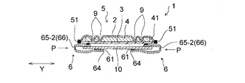
本発明の第3実施形態である生理用ナプキン1C(以下、「ナプキン1C」ともいう)の折り曲げ誘導手段について、以下に記載する。
尚、ナプキン1Cは、特に説明しない点はナプキン1と同様であり、ナプキン1の説明が適宜適用される。図10〜図13には、ナプキン1の構成要素等と同様の構成要素等に同一の符号を付してある。
The bending guiding means of the sanitary napkin 1C (hereinafter also referred to as “napkin 1C”) according to the third embodiment of the present invention will be described below.
The napkin 1C is the same as the napkin 1 unless otherwise described, and the description of the napkin 1 is applied as appropriate. 10-13, the same code | symbol is attached | subjected to the component similar to the component of the napkin 1, etc. FIG.

ウイング部6の折り曲げ線66を形成する折り曲げ誘導手段として、ナプキン1Cのウイング部形成材62は、図10〜図12に示すように、括れ部7での側縁512と本体部5の幅が最も広い位置での側縁511との間に、長手方向(X方向)に延びるエンボスライン65−2を有している。エンボスライン65−2は、図10,図11に示すように、平面視して、長手方向(X方向)に延びる矩形状であるが、特に矩形状に限定されず、長手方向(X方向)に延びていれば、平面視して、楕円状等であってもよい。   As a bending guiding means for forming the folding line 66 of the wing part 6, the wing part forming material 62 of the napkin 1C has a width of the side edge 512 and the main body part 5 at the constricted part 7, as shown in FIGS. Between the side edge 511 in the widest position, it has the emboss line 65-2 extended in a longitudinal direction (X direction). As shown in FIGS. 10 and 11, the emboss line 65-2 has a rectangular shape extending in the longitudinal direction (X direction) in plan view, but is not particularly limited to a rectangular shape, and the longitudinal direction (X direction). As long as it extends in a plan view, it may be oval in plan view.

上述のように構成されたナプキン1Cは、図13のようにショーツ等の下着に装着する際に形成されるウイング部6の折り曲げ線66が、図13に示すように、括れ部7での側縁512と本体部5の幅が最も広い位置での側縁511との間に配される。ナプキン1Cにおいては、特に、一本のエンボスライン65−2を有している為、エンボスライン65−2がウイング折り曲げ起点となり、折り曲げ線66が形成される。圧縮によりエンボスライン65−2を形成することで、エンボスライン65−2形成位置でのウイング部形成材62の厚みを薄くし、かつエンボスライン65−2が硬いことから、エンボスライン65−2を基点に両脇の柔らかいウイング部形成材62を湾曲させながら折り曲がることができる。   In the napkin 1C configured as described above, the fold line 66 of the wing portion 6 formed when being attached to underwear such as shorts as shown in FIG. 13 has a side at the constricted portion 7 as shown in FIG. It arrange | positions between the edge 512 and the side edge 511 in the position where the width | variety of the main-body part 5 is the widest. In particular, since the napkin 1C has one emboss line 65-2, the emboss line 65-2 serves as a wing fold starting point, and a fold line 66 is formed. By forming the emboss line 65-2 by compression, the thickness of the wing portion forming material 62 at the emboss line 65-2 formation position is reduced and the emboss line 65-2 is hard. The soft wing part forming material 62 on both sides can be bent while being bent at the base point.

これらの折り曲げ誘導手段で折り曲げることで、ウイング部形成材62は、しなやかに折り曲がり、折り曲げ線66が本体部5の括れ部7の側縁512と本体部5の幅が最も広い位置での側縁511との間に存在し、ウイング折れ曲がり端部が本体部5の裏面にうまく隠れるため、肌に直接当接することがなく、ウイング部6の折り曲げ線66の柔らかな部位のみが装着者の脚繰り肌に当接して、従来のちくちくした感触がなく、肌触りの良い装着感が得られる。   By bending with these bending guiding means, the wing portion forming material 62 is flexibly bent, and the side where the fold line 66 is located at the side edge 512 of the constricted portion 7 of the main body 5 and the width of the main body 5 is the widest. It exists between the edge 511, and the wing bent end is well hidden behind the back surface of the main body 5. Therefore, it does not directly contact the skin, and only the soft part of the fold line 66 of the wing 6 is the leg of the wearer. It is in contact with the skin and there is no conventional crisp feel, and a comfortable wearing feel can be obtained.

上述したナプキン1の製造方法は、当業者が考え得る任意の方法により製造することができるが、例えば、表面シート2の帯状原反に吸収体4を乗せ、2重の防漏溝9に対応する形状の凸部を有するエンボスロール間に通して2重の防漏溝9を形成した後、その上に、裏面シート3の帯状原反を積層し、熱エンボス加工を施し周縁シール部11を形成しながらカットすることにより本体部5を形成する。これとは別に、一枚の帯状シートから左右のウイング部形成材62を切り出し、一対のウイング部形成材62を形成する。本体部5の裏面シート3の両側部上それぞれに、ホットメルト型接着剤81を塗工し、ホットメルト型接着剤81を介して一対のウイング部形成材62を固定することにより製造することができる。   Although the manufacturing method of the napkin 1 mentioned above can be manufactured by any method conceivable by those skilled in the art, for example, the absorbent body 4 is placed on the belt-shaped raw fabric of the surface sheet 2 and corresponds to the double leak-proof groove 9. The double leak-proof groove 9 is formed by passing between embossing rolls having convex portions of the shape to be formed, and then the belt-like raw sheet of the back sheet 3 is laminated thereon, and heat embossing is performed to form the peripheral seal portion 11. The main body 5 is formed by cutting while forming. Separately from this, the left and right wing portion forming materials 62 are cut out from one strip-shaped sheet to form a pair of wing portion forming materials 62. It can be manufactured by applying hot-melt adhesive 81 on both sides of the back sheet 3 of the main body 5 and fixing a pair of wing-forming members 62 via the hot-melt adhesive 81. it can.

上述したナプキン1の形成材料について説明する。
表面シート2、裏面シート3、吸収体4としては、生理用ナプキン等の吸収性物品において従来用いられている各種の材料などを特に制限なく用いることができる。
例えば、表面シート2としては、単層又は多層構造の不織布や、開孔フィルム等を用いることができる。裏面シート3としては、液不透過性又は撥水性の樹脂フィルムや樹脂フィルムと不織布の積層体等を用いることができる。吸収体4としては、パルプ繊維等の繊維の集合体(不織布であっても良い)又はこれに吸水性ポリマーの粒子を保持させてなる吸収性コアを、透水性の薄紙や不織布からなるコアラップシートで被覆したものや、各種公知のポリマーシート等を用いることができる。
The formation material of the napkin 1 mentioned above is demonstrated.
As the top sheet 2, the back sheet 3, and the absorbent body 4, various materials conventionally used in absorbent articles such as sanitary napkins can be used without particular limitation.
For example, as the surface sheet 2, a single layer or multilayer nonwoven fabric, an apertured film, or the like can be used. As the back sheet 3, a liquid-impermeable or water-repellent resin film, a laminate of a resin film and a nonwoven fabric, or the like can be used. As the absorbent body 4, an aggregate of fibers such as pulp fibers (which may be a nonwoven fabric) or an absorbent core in which water-absorbing polymer particles are held therein is used as a core wrap made of water-permeable thin paper or nonwoven fabric. Those coated with a sheet, various known polymer sheets, and the like can be used.

ウイング部形成材62としては、肌当接面側が不織布であるもの、例えば、単層又は多層の不織布や、該不織布を肌当接面側に配した樹脂フィルムとの積層体等を用いることができる。単層の不織布としては、例えば、スパンボンド不織布、エアスルー不織布等が挙げられ、多層の不織布としては、スパンボンド−メルトブロー複合不織布(SM、SMS)や、エアスルー不織布とスパンボンド不織布の複合シート、エアスルー不織布とスパンボンド−メルトブロー複合不織布の複合シート等が挙げられる。
ウイング部形成材62の柔らかさ及び装着時のウイングの操作性の観点からは、ウイング部形成材62は、非伸縮性の不織布のみで構成されていることが好ましい。尚、非伸縮性であれば、不織布は、単層であっても多層であってもよいが、ウイング部形成材の柔らかさの観点から、単層の方が好ましい。
As the wing portion forming material 62, a material in which the skin contact surface side is a nonwoven fabric, for example, a single layer or multilayer nonwoven fabric, or a laminate with a resin film in which the nonwoven fabric is disposed on the skin contact surface side, or the like is used. it can. Examples of the single layer nonwoven fabric include a spunbond nonwoven fabric and an air-through nonwoven fabric, and examples of the multilayer nonwoven fabric include a spunbond-meltblown composite nonwoven fabric (SM, SMS), a composite sheet of an air-through nonwoven fabric and a spunbond nonwoven fabric, and air-through. A composite sheet of a nonwoven fabric and a spunbond-melt blow composite nonwoven fabric may be used.
From the viewpoint of the softness of the wing portion forming material 62 and the operability of the wing at the time of wearing, the wing portion forming material 62 is preferably composed only of a non-stretchable nonwoven fabric. The non-woven fabric may be a single layer or multiple layers as long as it is non-stretchable, but a single layer is preferred from the viewpoint of the softness of the wing portion forming material.

帯状接合部8を形成するためのホットメルト型接着剤としては、弾性を有するポリマー成分であるスチレンーブタジエン系やスチレンーイソプレン系のもの、また常温(体温相当)で粘着性がほとんど無い低タック性のホットメルト等が挙げられるが、動きにおける追従性の点から、弾性のある樹脂組成を有することが好ましく、それらの中でも、接合の維持の点から、タック性を有する接着剤が好ましい。   Hot melt adhesives for forming the band-like joint 8 include styrene-butadiene and styrene-isoprene, which are polymer components having elasticity, and low tack that has almost no stickiness at room temperature (equivalent to body temperature). However, it is preferable to have an elastic resin composition from the viewpoint of followability in movement, and among them, an adhesive having tackiness is preferable from the viewpoint of maintaining bonding.

また、本発明の吸収性物品においては、本体部5における吸収体4と裏面シート3との間も接着剤によって接合することが好ましい。但し、この接着剤は、スパイラルパターン等のパターン塗工や、帯状接合部8を形成するホットメルト型接着剤81よりも低坪量に塗工することが好ましい。   Moreover, in the absorbent article of this invention, it is preferable to join between the absorber 4 and the back surface sheet 3 in the main-body part 5 with an adhesive agent. However, this adhesive is preferably applied at a lower basis weight than a pattern application such as a spiral pattern or a hot-melt adhesive 81 that forms the band-shaped joint 8.

上述した本発明の吸収性物品の実施形態であるナプキン1(以下、「ナプキン1」ともいう。)の装着方法は、ナプキン1のウイング部6の裏面にはショーツに固定するホットメルト接着剤(ウイング部粘着部61)が形成されており、ウイング部6を折り返してショーツの股下部にホットメルト接着剤(ウイング部粘着部61)を介してウイング部6を固定する際に、折り曲げ誘導手段を折り曲げ基点としてウイング部6を折り曲げ、ウイング部6の折り曲げ線66を、括れ部7での側縁512と本体部5の幅が最も広い位置での側縁511との間に配し、ショーツの股下部にナプキン1を固定して装着する。   The mounting method of the napkin 1 (hereinafter also referred to as “napkin 1”), which is an embodiment of the absorbent article of the present invention described above, is a hot melt adhesive (fixed to shorts on the back surface of the wing portion 6 of the napkin 1). The wing part adhesive part 61) is formed, and when the wing part 6 is folded back and the wing part 6 is fixed to the crotch part of the shorts via the hot melt adhesive (the wing part adhesive part 61), the bending guiding means is used. The wing part 6 is bent as a bending base point, and a fold line 66 of the wing part 6 is arranged between the side edge 512 at the constricted part 7 and the side edge 511 at the position where the width of the main body part 5 is the widest. The napkin 1 is fixed and attached to the crotch.

上述した本発明の吸収性物品の実施形態であるナプキン1(以下、「ナプキン1」ともいう。)を使用した際の作用効果について説明する。
ナプキン1のウイング部6は、図2,図3に示すように、ウイング部形成材62の一側縁63側が裏面シート3の非肌対向面に固定されているので、図4に示すように、ショーツ等の下着のクロッチ部10に装着する際に、本体部5の側縁51を下方に巻き込むことがない。従って、本体部5の全面を使って体液を有効に吸収することができる。また、図5に示すように、ウイング部6の折り曲げ線66が、括れ部6での側縁512と本体部5の幅が最も広い位置での側縁511との間に配されるので、下着のクロッチ部に取り付けて使用する際に、本体部5の側縁51、特に、括れ部6での側縁512が使用者の肌に当たり難く、ウイング部6の折り曲げ線66の位置における折り曲げ部分も使用者の肌に当たり難い。従って、ナプキン1の使用感が向上する。
The effect at the time of using the napkin 1 (henceforth "napkin 1") which is embodiment of the absorbent article of this invention mentioned above is demonstrated.
2 and 3, the wing portion 6 of the napkin 1 is fixed to the non-skin facing surface of the back sheet 3 on one side edge 63 side as shown in FIG. 4. When attaching to the crotch part 10 of underwear such as shorts, the side edge 51 of the main body part 5 is not entangled downward. Therefore, the body fluid can be effectively absorbed using the entire surface of the main body 5. Further, as shown in FIG. 5, the fold line 66 of the wing part 6 is disposed between the side edge 512 at the constricted part 6 and the side edge 511 at the position where the width of the main body part 5 is the widest. When used by attaching to the crotch part of the underwear, the side edge 51 of the main body part 5, particularly the side edge 512 of the constricted part 6, does not easily hit the user's skin, and the bent part at the position of the fold line 66 of the wing part 6 It is hard to hit the user's skin. Therefore, the feeling of use of the napkin 1 is improved.

また、ナプキン1は、図2に示すように、帯状接合部8が、吸収体4と重なっているため、ナプキン1の使用時に、ウイング部6を引っ張ってもウイング部6が本体部5から取れ難い。また、装着させやすく、使用時の違和感を少ない。   Further, as shown in FIG. 2, the napkin 1 has the band-shaped joint portion 8 overlapped with the absorber 4, so that when the napkin 1 is used, the wing portion 6 can be removed from the main body portion 5 even if the wing portion 6 is pulled. hard. In addition, it is easy to put on and there is little discomfort during use.

本発明は、上述した実施形態に何ら制限されるものではなく、適宜変更可能である。
例えば、上述のナプキン1においては、図2に示すように、ウイング部形成材62が、一側縁63側のX方向の長さL1が、ナプキン1のX方向の長さLに比して短いものであるが、一側縁63側がナプキン1の全長に亘って形成されており、一側縁63側のX方向の長さL1が、ナプキン1のX方向の長さLと同じ長さであってもよい。
The present invention is not limited to the embodiment described above, and can be modified as appropriate.
For example, in the napkin 1 described above, as shown in FIG. 2, the wing portion forming material 62 has a length L1 in the X direction on the side edge 63 side as compared with a length L in the X direction of the napkin 1. Although it is short, the one side edge 63 side is formed over the entire length of the napkin 1, and the length L1 in the X direction on the one side edge 63 side is the same length as the length L in the X direction of the napkin 1 It may be.

また、上述のナプキン1においては、図2,図3に示すように、帯状接合部8が吸収体4と重なっているが、重なっていなくてもよい。即ち、帯状接合部8が吸収体4の側縁41と本体部5の側縁51との間に設けられていてもよい。
また、上述のナプキン1においては、図1,図2に示すように、ウイング部形成材62がスリット部分65を有しているが、有していなくてもよい。
Moreover, in the above-mentioned napkin 1, as shown to FIG. 2, FIG. 3, although the strip | belt-shaped junction part 8 has overlapped with the absorber 4, it does not need to overlap. That is, the belt-like joint portion 8 may be provided between the side edge 41 of the absorbent body 4 and the side edge 51 of the main body portion 5.
Moreover, in the above-mentioned napkin 1, as shown in FIG. 1, FIG. 2, although the wing part formation material 62 has the slit part 65, it does not need to have it.

また、ウイング部6は、粘着部61を介してショーツのクロッチ部10に固定するものに限られず、機械的面ファスナーのオス部材からなる係合部を用いてクロッチ部10に固定するものや、粘着部や機械的面ファスナーからなる係合部を介してウイング部同士を連結して固定するもの等であっても良い。また、本発明の吸収性物品は、生理用ナプキンの他、パンティライナー(おりものシート)、失禁パッド等であっても良い。
また、表面シート2として、全域が液透過性のものに代えて、液透過性の中央シートの両側それぞれに、撥水性の不織布からなるサイドシートが連結した構成の複合シートを用いることもできる。
Moreover, the wing part 6 is not restricted to what is fixed to the crotch part 10 of shorts via the adhesion part 61, What is fixed to the crotch part 10 using the engaging part which consists of a male member of a mechanical hook-and-loop fastener, The thing etc. which connect and fix wing parts via the engaging part which consists of an adhesion part or a mechanical hook-and-loop fastener, etc. may be sufficient. In addition to the sanitary napkin, the absorbent article of the present invention may be a panty liner (origami sheet), an incontinence pad, or the like.
Moreover, as the surface sheet 2, a composite sheet having a structure in which a side sheet made of a water-repellent nonwoven fabric is connected to each of both sides of the liquid-permeable central sheet instead of the liquid-permeable center sheet.

1 生理用ナプキン(吸収性物品)
2 表面シート
3 裏面シート
4 吸収体
41 吸収体の側縁
5 本体部
51 本体部の側縁
511 本体部の幅が最も広い位置における側縁
512 括れ部における側縁
6 ウイング部
61 ウイング部粘着部
62 ウイング部形成材
63 一側部(内側部),64 他側部(外側部)
65 スリット部分、65−1 中間固定部 、65−2 エンボスライン
66 折り曲げ線
7 括れ部
8 帯状接合部
81 ホットメルト型接着剤
9 防漏溝
10 ショーツのクロッチ部
A 中央部(左右にウイング部を有する部分)
B 前方部
C 後方部
1 Sanitary napkin (absorbent article)
2 Top sheet 3 Back sheet 4 Absorber 41 Side edge 5 of absorbent body 51 Main body 51 Side edge of main body 511 Side edge at the position where the width of the main body is widest 512 Side edge 6 at the constricted section 6 Wing section 61 Wing section adhesive section 62 Wing part forming material 63 One side part (inner part), 64 Other side part (outer part)
65 slit part, 65-1 intermediate fixing part, 65-2 emboss line 66 fold line 7 constricted part 8 band-like joint part 81 hot melt adhesive 9 leak-proof groove 10 crotch part A of shorts central part (with wing parts on the left and right) Part)
B Front part C Rear part

Claims (7)

表面シート、裏面シート及びこれら両シート間に配された吸収体を具備する縦長の本体部、及び該本体部の両側縁から延出する一対のウイング部を有する吸収性物品であって、
前記本体部は、前記ウイング部の位置において内方に括れる括れ部を有しており、
前記括れ部は、括れた前記表面シートの縁部及び括れた前記裏面シートの縁部が互いにシールされて形成されており、前記吸収体の側縁は、前記括れ部よりも内方に位置しており、
前記ウイング部は、前記表面シート及び前記裏面シートとは別体の肌当接面側が不織布であるウイング部形成材を用い、該ウイング部形成材の前記本体部に位置する一側縁側が前記裏面シートの非肌対向面に固定され、他側縁側が前記本体部の前記括れ部より外方に延出するように配されて形成されており、
前記吸収性物品を下着に装着する際に形成される前記ウイング部の折り曲げ線が、前記括れ部での側縁と前記本体部の幅が最も広い位置での側縁との間に配される吸収性物品。
An absorbent article having a top sheet, a back sheet and a vertically long main body comprising an absorbent body disposed between both sheets, and a pair of wings extending from both side edges of the main body,
The main body portion has a constricted portion that is bound inward at the position of the wing portion,
The constricted portion is formed by sealing an edge portion of the constricted top sheet and an edge portion of the constricted back sheet, and a side edge of the absorber is located inward of the constricted portion. And
The wing part uses a wing part forming material in which the skin contact surface side separate from the top sheet and the back sheet is a non-woven fabric, and one side edge side of the wing part forming material located in the main body part is the back surface It is fixed to the non-skin facing surface of the sheet, and the other side edge side is formed so as to extend outward from the constricted part of the main body part,
A fold line of the wing portion formed when the absorbent article is attached to an undergarment is disposed between a side edge at the constricted portion and a side edge at a position where the width of the main body portion is the widest. Absorbent article.
前記ウイング部形成材は、該ウイング部形成材と前記裏面シートとの固定により形成される帯状接合部と前記本体部の前記括れ部との間の領域に、該ウイング部形成材と該裏面シートとが固定された中間固定部を折り曲げ誘導手段として備えている請求項1記載の吸収性物品。   The wing portion forming material is formed in a region between a band-shaped joint portion formed by fixing the wing portion forming material and the back sheet and the constricted portion of the main body portion, and the back sheet. The absorbent article according to claim 1, further comprising an intermediate fixing portion to which is fixed as bending induction means. 前記ウイング部形成材は、前記括れ部での側縁と前記本体部の幅が最も広い位置での側縁との間に、折り曲げ誘導手段を備えた請求項1記載の吸収性物品。   2. The absorbent article according to claim 1, wherein the wing portion forming material includes a bending guide means between a side edge at the constricted portion and a side edge at a position where the width of the main body portion is the widest. 前記ウイング部形成材の前記折り曲げ誘導手段は、該ウイング部形成材に長手方向に延びるエンボスライン及び/又はスリットである請求項3記載の吸収性物品。   The absorbent article according to claim 3, wherein the bending guide means of the wing portion forming material is an emboss line and / or a slit extending in the longitudinal direction of the wing portion forming material. 前記ウイング部形成材と前記裏面シートとの固定により形成される帯状接合部は、前記吸収体と重なっている請求項1〜4の何れか1項に記載の吸収性物品。   The absorbent article according to any one of claims 1 to 4, wherein a band-shaped joint formed by fixing the wing part forming material and the back sheet overlaps the absorber. 前記ウイング部形成材は、非伸縮性の不織布のみで構成されている請求項1〜5の何れか1項に記載の吸収性物品。   The absorbent article according to any one of claims 1 to 5, wherein the wing portion forming material is composed only of a non-stretchable nonwoven fabric. 請求項2〜6の何れか1項に記載の吸収性物品の装着方法であって、該吸収性物品の前記ウイング部の裏面にはショーツに固定するホットメルト接着剤が形成されており、該ウイング部を折り返してショーツの股下部に該ホットメルト接着剤を介して該ウイング部を固定する際に、前記折り曲げ誘導手段を折り曲げ基点として該ウイング部を折り曲げ、前記ウイング部の前記折り曲げ線を、前記括れ部での側縁と前記本体部の幅が最も広い位置での側縁との間に配し、前記ショーツの股下部に前記吸収性物品を固定して装着する吸収性物品の装着方法。   It is the mounting method of the absorbent article of any one of Claims 2-6, Comprising: The hot-melt-adhesive fixed to shorts is formed in the back surface of the said wing part of this absorbent article, When the wing portion is folded and fixed to the crotch portion of the shorts via the hot melt adhesive, the wing portion is bent using the bending guide means as a bending base point, and the fold line of the wing portion is A method of mounting an absorbent article that is disposed between a side edge of the constricted part and a side edge of the body part at the widest position, and the absorbent article is fixedly attached to a crotch part of the shorts. .
JP2010258584A 2010-11-19 2010-11-19 Absorbent articles Active JP5685421B2 (en)

Priority Applications (1)

Application Number Priority Date Filing Date Title
JP2010258584A JP5685421B2 (en) 2010-11-19 2010-11-19 Absorbent articles

Applications Claiming Priority (1)

Application Number Priority Date Filing Date Title
JP2010258584A JP5685421B2 (en) 2010-11-19 2010-11-19 Absorbent articles

Publications (2)

Publication Number Publication Date
JP2012105908A true JP2012105908A (en) 2012-06-07
JP5685421B2 JP5685421B2 (en) 2015-03-18

Family

ID=46492217

Family Applications (1)

Application Number Title Priority Date Filing Date
JP2010258584A Active JP5685421B2 (en) 2010-11-19 2010-11-19 Absorbent articles

Country Status (1)

Country Link
JP (1) JP5685421B2 (en)

Cited By (5)

* Cited by examiner, † Cited by third party
Publication number Priority date Publication date Assignee Title
JP2014198195A (en) * 2013-03-29 2014-10-23 大王製紙株式会社 Absorbent article
JP2016123739A (en) * 2015-01-06 2016-07-11 王子ホールディングス株式会社 Absorbent article
CN112218607A (en) * 2018-06-19 2021-01-12 宝洁公司 Absorbent article with functionally shaped topsheet and method of manufacture
US11547613B2 (en) 2017-12-05 2023-01-10 The Procter & Gamble Company Stretch laminate with beamed elastics and formed nonwoven layer
US11819393B2 (en) 2019-06-19 2023-11-21 The Procter & Gamble Company Absorbent article with function-formed topsheet, and method for manufacturing

Citations (9)

* Cited by examiner, † Cited by third party
Publication number Priority date Publication date Assignee Title
JPH09500562A (en) * 1993-07-22 1997-01-21 ザ、プロクター、エンド、ギャンブル、カンパニー Absorbent product with underwear cover member having an extension area
JPH11508164A (en) * 1995-06-22 1999-07-21 ザ、プロクター、エンド、ギャンブル、カンパニー Absorbent product with underwear cover element suitable for folding around the underwear edge
JP2003527929A (en) * 2000-03-29 2003-09-24 ザ、プロクター、エンド、ギャンブル、カンパニー Disposable absorbent article with removable and re-attachable positioning flap
JP2005040235A (en) * 2003-07-24 2005-02-17 Kao Corp Absorbing article
US20050131372A1 (en) * 2003-12-10 2005-06-16 Kimberly-Clark Worldwide, Inc. Absorbent articles with removable protective wing portions
JP2005288197A (en) * 2005-07-04 2005-10-20 Daio Paper Corp Absorptive article with wing
JP2006192261A (en) * 2004-12-15 2006-07-27 Kao Corp Package structure of absorbent article
JP2008161303A (en) * 2006-12-27 2008-07-17 Kao Corp Absorbent article
JP2011156239A (en) * 2010-02-03 2011-08-18 Unicharm Corp Absorptive article

Patent Citations (9)

* Cited by examiner, † Cited by third party
Publication number Priority date Publication date Assignee Title
JPH09500562A (en) * 1993-07-22 1997-01-21 ザ、プロクター、エンド、ギャンブル、カンパニー Absorbent product with underwear cover member having an extension area
JPH11508164A (en) * 1995-06-22 1999-07-21 ザ、プロクター、エンド、ギャンブル、カンパニー Absorbent product with underwear cover element suitable for folding around the underwear edge
JP2003527929A (en) * 2000-03-29 2003-09-24 ザ、プロクター、エンド、ギャンブル、カンパニー Disposable absorbent article with removable and re-attachable positioning flap
JP2005040235A (en) * 2003-07-24 2005-02-17 Kao Corp Absorbing article
US20050131372A1 (en) * 2003-12-10 2005-06-16 Kimberly-Clark Worldwide, Inc. Absorbent articles with removable protective wing portions
JP2006192261A (en) * 2004-12-15 2006-07-27 Kao Corp Package structure of absorbent article
JP2005288197A (en) * 2005-07-04 2005-10-20 Daio Paper Corp Absorptive article with wing
JP2008161303A (en) * 2006-12-27 2008-07-17 Kao Corp Absorbent article
JP2011156239A (en) * 2010-02-03 2011-08-18 Unicharm Corp Absorptive article

Cited By (6)

* Cited by examiner, † Cited by third party
Publication number Priority date Publication date Assignee Title
JP2014198195A (en) * 2013-03-29 2014-10-23 大王製紙株式会社 Absorbent article
JP2016123739A (en) * 2015-01-06 2016-07-11 王子ホールディングス株式会社 Absorbent article
US11547613B2 (en) 2017-12-05 2023-01-10 The Procter & Gamble Company Stretch laminate with beamed elastics and formed nonwoven layer
US11969325B2 (en) 2018-01-25 2024-04-30 The Procter & Gamble Company Absorbent article with function-formed topsheet, and method for manufacturing
CN112218607A (en) * 2018-06-19 2021-01-12 宝洁公司 Absorbent article with functionally shaped topsheet and method of manufacture
US11819393B2 (en) 2019-06-19 2023-11-21 The Procter & Gamble Company Absorbent article with function-formed topsheet, and method for manufacturing

Also Published As

Publication number Publication date
JP5685421B2 (en) 2015-03-18

Similar Documents

Publication Publication Date Title
JP6039956B2 (en) Pants-type absorbent article
JP4522308B2 (en) Disposable diaper and method for producing the same
JP5577085B2 (en) Pants-type disposable diapers
JP2011156239A (en) Absorptive article
JP6424129B2 (en) Absorbent articles
JP5789407B2 (en) Pants-type absorbent article
JP5685421B2 (en) Absorbent articles
JP2017148111A (en) Underpants type absorbent article
JP5693267B2 (en) Absorbent articles
JP2017060635A (en) Absorbent article for women
JP6128980B2 (en) Disposable pants-type diapers
JP5978349B1 (en) Absorbent articles
JP4338619B2 (en) Absorbent articles
JP2023080295A (en) Expansion type worn article
JP5671296B2 (en) Absorbent articles
JP5149105B2 (en) Absorbent articles
WO2021132292A1 (en) Underpants-type absorbent article
JP5149104B2 (en) Absorbent articles
JP7152256B2 (en) absorbent article
JP2010115337A (en) Absorbent article
JP2012095833A (en) Absorbent article
JP2009136600A (en) Absorbent article
JP6181818B1 (en) Absorbent articles
CN216876843U (en) Pants-type absorbent article
JP5978350B1 (en) Absorbent articles

Legal Events

Date Code Title Description
A621 Written request for application examination

Free format text: JAPANESE INTERMEDIATE CODE: A621

Effective date: 20130913

A977 Report on retrieval

Free format text: JAPANESE INTERMEDIATE CODE: A971007

Effective date: 20140414

A131 Notification of reasons for refusal

Free format text: JAPANESE INTERMEDIATE CODE: A131

Effective date: 20140527

A521 Request for written amendment filed

Free format text: JAPANESE INTERMEDIATE CODE: A523

Effective date: 20140704

TRDD Decision of grant or rejection written
A01 Written decision to grant a patent or to grant a registration (utility model)

Free format text: JAPANESE INTERMEDIATE CODE: A01

Effective date: 20150113

A61 First payment of annual fees (during grant procedure)

Free format text: JAPANESE INTERMEDIATE CODE: A61

Effective date: 20150119

R151 Written notification of patent or utility model registration

Ref document number: 5685421

Country of ref document: JP

Free format text: JAPANESE INTERMEDIATE CODE: R151

R250 Receipt of annual fees

Free format text: JAPANESE INTERMEDIATE CODE: R250

R250 Receipt of annual fees

Free format text: JAPANESE INTERMEDIATE CODE: R250

R250 Receipt of annual fees

Free format text: JAPANESE INTERMEDIATE CODE: R250

R250 Receipt of annual fees

Free format text: JAPANESE INTERMEDIATE CODE: R250

R250 Receipt of annual fees

Free format text: JAPANESE INTERMEDIATE CODE: R250

R250 Receipt of annual fees

Free format text: JAPANESE INTERMEDIATE CODE: R250

R250 Receipt of annual fees

Free format text: JAPANESE INTERMEDIATE CODE: R250