JP2012105407A - Power storage system - Google Patents
Power storage system Download PDFInfo
- Publication number
- JP2012105407A JP2012105407A JP2010250047A JP2010250047A JP2012105407A JP 2012105407 A JP2012105407 A JP 2012105407A JP 2010250047 A JP2010250047 A JP 2010250047A JP 2010250047 A JP2010250047 A JP 2010250047A JP 2012105407 A JP2012105407 A JP 2012105407A
- Authority
- JP
- Japan
- Prior art keywords
- charge
- power storage
- discharge control
- discharge
- control characteristic
- Prior art date
- Legal status (The legal status is an assumption and is not a legal conclusion. Google has not performed a legal analysis and makes no representation as to the accuracy of the status listed.)
- Pending
Links
Images


Classifications
-
- Y—GENERAL TAGGING OF NEW TECHNOLOGICAL DEVELOPMENTS; GENERAL TAGGING OF CROSS-SECTIONAL TECHNOLOGIES SPANNING OVER SEVERAL SECTIONS OF THE IPC; TECHNICAL SUBJECTS COVERED BY FORMER USPC CROSS-REFERENCE ART COLLECTIONS [XRACs] AND DIGESTS
- Y02—TECHNOLOGIES OR APPLICATIONS FOR MITIGATION OR ADAPTATION AGAINST CLIMATE CHANGE
- Y02E—REDUCTION OF GREENHOUSE GAS [GHG] EMISSIONS, RELATED TO ENERGY GENERATION, TRANSMISSION OR DISTRIBUTION
- Y02E60/00—Enabling technologies; Technologies with a potential or indirect contribution to GHG emissions mitigation
- Y02E60/10—Energy storage using batteries
Landscapes
- Charge And Discharge Circuits For Batteries Or The Like (AREA)
- Secondary Cells (AREA)
Abstract
Description
本発明は、電力系統に充放電する蓄電システムに関する。 The present invention relates to a power storage system that charges and discharges an electric power system.
一般に、電気鉄道の直流電力供給システム(直流き電システム)に蓄電装置を設置することが知られている。蓄電装置は、列車が回生する回生電力を吸収したり、架線電圧が低下した際に放電したりすることで、架線電圧を補償する。 Generally, it is known to install a power storage device in a DC power supply system (DC feeding system) of an electric railway. The power storage device compensates for the overhead line voltage by absorbing regenerative electric power regenerated by the train or discharging when the overhead line voltage decreases.
また、列車のき電回路上の負荷分布は、時間帯によって大きく異なる。このため、ラッシュ時と閑散時では、蓄電装置への要求が異なる。従って、時間帯によって、蓄電装置の充放電制御方法が異なる。 Also, the load distribution on the train feeding circuit varies greatly depending on the time of day. For this reason, the request | requirement to an electrical storage apparatus differs at the time of a rush and a quiet time. Therefore, the charge / discharge control method of the power storage device differs depending on the time period.
そこで、蓄電装置の充放電制御方法を時間帯別に切り替えることが知られている。 Therefore, it is known to switch the charge / discharge control method of the power storage device according to time zones.
しかしながら、蓄電装置の充放電制御方法を時間帯別に切り替えて制御する場合、列車ダイヤが運転整理の影響で大きく変更されると、期待した充放電制御による効果を得られなくなる可能性がある。これは、予測した負荷状態と実際の負荷状態が適合しなくなるからである。 However, when the charge / discharge control method of the power storage device is switched and controlled for each time zone, if the train schedule is greatly changed due to the influence of operation arrangement, there is a possibility that the expected effect of charge / discharge control cannot be obtained. This is because the predicted load state and the actual load state are not matched.
例えば、列車密度の薄い閑散時に回生失効を抑制するように蓄電装置を制御しているときに、運転整理が行われ、列車密度が高い状態になったと仮定する。このような状況下で有効な蓄電装置の制御方法は、回生失効を抑制する充放電制御ではなく、パンタ点電圧降下を補償する制御である。このような場合に、回生失効を抑制する充放電制御を行っても、充放電制御による期待した効果は得られない。 For example, it is assumed that when the power storage device is controlled so as to suppress the regeneration invalidity when the train density is low, the operation is organized and the train density is high. An effective method for controlling the power storage device under such circumstances is not charge / discharge control that suppresses regenerative expiration, but control that compensates for a punter point voltage drop. In such a case, even if charge / discharge control that suppresses regenerative revocation is performed, the expected effect of charge / discharge control cannot be obtained.
そこで、本発明の実施形態の目的は、電力系統の負荷状態に応じて効果的に充放電することのできる蓄電システムを提供することにある。 Then, the objective of embodiment of this invention is to provide the electrical storage system which can be charged / discharged effectively according to the load state of an electric power grid | system.
本発明の実施形態の観点に従った蓄電システムは、電力系統に接続された蓄電手段と、前記電力系統の電圧を計測する電圧計測手段と、時間に基づいて、前記蓄電手段の充放電を制御するための第1の充放電制御特性を生成する第1の充放電制御特性生成手段と、充電及び放電のいずれも対応するように前記蓄電手段の充放電を制御するための第2の充放電制御特性を生成する第2の充放電制御特性生成手段と、前記第1の充放電制御特性生成手段により生成された前記第1の充放電制御特性又は前記第2の充放電制御特性生成手段により生成された前記第2の充放電制御特性を用いて、前記電圧計測手段により計測された電圧に基づいて、前記蓄電手段の充放電を制御する充放電制御手段と、前記蓄電手段の充放電が効果的か否かを判定する判定手段と、前記判定手段により前記蓄電手段の充放電が効果的でないと判定された場合、前記充放電制御手段に用いる充放電制御特性を切り替える充放電制御特性切替手段とを備えている。 A power storage system according to an embodiment of the present invention controls power storage means connected to a power system, voltage measurement means for measuring the voltage of the power system, and charge / discharge of the power storage means based on time A first charge / discharge control characteristic generating means for generating a first charge / discharge control characteristic for performing a charge, and a second charge / discharge for controlling the charge / discharge of the power storage means so as to correspond to both charge and discharge A second charge / discharge control characteristic generation unit that generates a control characteristic; and the first charge / discharge control characteristic generated by the first charge / discharge control characteristic generation unit or the second charge / discharge control characteristic generation unit. Charge / discharge control means for controlling charge / discharge of the power storage means based on the voltage measured by the voltage measurement means using the generated second charge / discharge control characteristics, and charge / discharge of the power storage means Determine if it is effective And determining means, when the charge and discharge of the accumulator unit is determined not to be effective by the determination unit, and a charge and discharge control characteristic switching means for switching the charging and discharging control characteristic to be used for the charging and discharging control unit.
以下図面を参照して、本発明の実施形態を説明する。 Embodiments of the present invention will be described below with reference to the drawings.
(第1の実施形態)
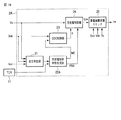
図1は、本発明の第1の実施形態に係る蓄電システム1の適用された電気鉄道の直流電力供給システム(直流き電システム)10の構成を示す構成図である。なお、以降の図における同一部分には同一符号を付してその詳しい説明を省略し、異なる部分について主に述べる。以降の実施形態も同様にして重複する説明を省略する。
(First embodiment)
FIG. 1 is a configuration diagram showing a configuration of a DC power supply system (DC feeding system) 10 for an electric railway to which a
直流電力供給システム10は、複数の変圧器91と、複数の整流器92と、電車線(架線)93と、蓄電システム1と、TCR(遠方監視制御装置の送受信器)11と、伝送路12とを備えている。列車90は、直流電力供給システム10から供給される直流電力により走行する。
The DC
変圧器91及び整流器92は、き電区間毎に設けられている。変圧器91及び整流器92は、変電所から供給される交流電力を電車線93に供給するために適した直流電圧に変換する。
The
電車線93は、整流器92から受電した直流電力を列車90に供給する。
The
TCR11は、伝送路12を介して、遠方監視制御装置(電力管理システム又は運行管理システム等)と接続されている。TCR11は、遠方監視制御装置が蓄電システム1と情報の送受信をするための送受信器である。
The TCR 11 is connected to a remote monitoring control device (such as a power management system or an operation management system) via the
蓄電システム1は、遠方監視制御装置から受信する各種情報、及び直流電力供給システム10における各箇所の電流又は電圧などの電気量に基づいて、充放電する。これにより、蓄電システム1は、列車90が回生する回生電力を吸収したり、電車線93の電圧低下時に電車線93の電圧を補償するために放電したりする。
The
蓄電システム1は、制御部2と、蓄電装置3と、電圧検出器4と、電流検出器5とを備えている。
The
蓄電装置3は、電車線93と電気的に接続されている。蓄電装置3は、直流チョッパなどの変換器を備えている。変換器は、制御部2により制御される。変換器が駆動することにより、蓄電装置3は、電力を充電又は放電する。蓄電装置3は、蓄電状態を示すSOC(State of Charge)情報Sob、蓄電装置3を構成する各セル(電池)の温度Tb、及び蓄電装置3の端子間電圧Vdcなどを含む蓄電装置3に関する情報(蓄電装置情報)Dbを制御部2に送信する。
The
電圧検出器4は、電車線93の架線電圧Vsを計測するために検出する。電圧検出器4は、検出した架線電圧Vsを制御部2に出力する。
The
電流検出器5は、蓄電装置3の出力電流(放電電流又は充電電流)Ioutを計測するために検出する。電流検出器5は、検出した出力電流Ioutを制御部2に出力する。
The
制御部2は、蓄電装置3から受信した蓄電装置情報Db、電圧検出器4により検出された架線電圧Vs、電流検出器5により検出された出力電流Iout、及びTCR11から受信する各種情報に基づいて、蓄電装置3の出力電流Ioutを制御するための電流指令値I*を演算する。制御部2がTCR11から受信する各種情報は、例えば、運行管理システムから送信される列車ダイヤに関する情報である。制御部2は、演算した電流指令値I*を蓄電装置3に送信することにより、蓄電装置3の充放電を制御する。
Based on the power storage device information Db received from the
図2は、本実施形態に係る蓄電システム1の制御部2の構成を示す構成図である。
FIG. 2 is a configuration diagram illustrating a configuration of the
制御部2は、自立判定部21と、充放電制御特性生成部22と、SOC制御部23と、充放電制御部24と、蓄電装置保護リミッタ25とを備えている。
The
自立判定部21には、蓄電装置3から受信するSOC情報Sob、電圧検出器4により検出された架線電圧Vs、及び電流検出器5により検出された出力電流Ioutが入力される。自立判定部21は、SOC情報Sob、架線電圧Vs、及び出力電流Ioutに基づいて、充放電制御が効果的に実施されているか否かを判定する。自立判定部21は、充放電制御が効果的に実施されていないと判定した場合、充放電制御特性生成部22に制御モードMDを切り替えるための切替指令を出力する。
The SOC information Sob received from the
図3を参照して、自立判定部21による判定方法について説明する。
With reference to FIG. 3, the determination method by the
図3は、本実施形態に係る自立判定部21による判定を説明するためのグラフ図である。
FIG. 3 is a graph for explaining the determination by the self-supporting
自立判定部21は、き電線入力エネルギの計画値PLと実績値REを比較する。実績値REは、SOC情報Sob、架線電圧Vs、及び出力電流Ioutに基づいて、演算される。計画値PLは、予め自立判定部21に記憶されている。計画値PLは、例えば、過去に効果的に充放電制御が実施されていたときの実績値である。
The
図3では、時間の経過と共に、計画値PLと実績値REが乖離している。自立判定部21は、乖離する幅及び継続時間を予め定義されている目的別(例えば、電車線93への放電を目的とする場合又は電車線93からの充電を目的とする場合)の評価関数に代入することで、充放電制御が効果的に実施されているか否かを判定する。評価関数による評価は、基本的には、乖離する幅が広い程、又は乖離状態の継続時間(例えば、乖離する幅が所定値以上の継続時間)が長い程、充放電制御が効果的に実施されていないと判定する。
In FIG. 3, the planned value PL and the actual value RE deviate with time. The
図4は、本実施形態に係る充放電制御特性生成部22の構成を示す構成図である。
FIG. 4 is a configuration diagram illustrating a configuration of the charge / discharge control
充放電制御特性生成部22は、制御モード切替部221と、屈折点パラメータ生成部222とを備えている。
The charge / discharge control
制御モード切替部221は、制御モードを決定する。制御モード切替部221は、自立判定部21から入力される切替指令又はTCR11から入力される遠方監視制御装置の切替指令に基づいて、制御モードMDを切り替える。制御モード切替部221の接点Aが選択された場合、設定部STAに設定されている制御モード1が選択される。制御モード切替部221の接点Bが選択された場合、設定部STBに設定されている制御モード2が選択される。制御モード切替部221は、選択した制御モードMDを屈折点パラメータ生成部222及びSOC制御部23に出力する。
The control
制御モード切替部221は、通常時は、制御モード1が選択されている。制御モード切替部221は、自立判定部21から制御モードMDを切り替えるための切替指令を受信すると、制御モード1から制御モード2に切り替える。この他に、制御モード切替部221は、手動又は運転管理システムからの切替指令により、制御モード1から制御モード2に切り替わる。また、制御モード切替部221は、ダイヤの遅延時分から自動的に切り替えを判定することにより切り替えてもよい。制御モード2から制御モード1への復帰は、手動又は運転管理システムからのリセット信号などにより行われる。例えば、指令員がダイヤの復帰を確認して、リセット指令を与える。または、ダイヤの遅延時分から自動的に復帰を判定することにより、リセット指令が与えられる。
In the control
制御モード1は、電力管理システムの情報伝送網(伝送路12を含むネットワークなど)を活用した制御である。変電所間をつなぐ情報伝送網を利用して、各変電所の回線別電流又はき電線電圧などの状態情報を蓄電システム1に伝送させる。蓄電システム1は、情報伝送網から伝送された情報に基づいて、自律制御により充放電を実施する。
The
制御モード2は、単一の充放電制御特性により充放電制御する制御モードである。制御モード2で用いる電圧−電流特性は、閑散時及びラッシュ時などのどのような負荷状態でも常に一定の充放電効果が得られる制御を行う充放電制御特性である。制御モード切替部221は、制御モード1による蓄電装置3の充放電制御が効果的でない場合、制御モード2に切り換わる。
The
図5は、本実施形態に係る充放電制御部24による制御に用いられる充放電制御特性を示す特性図である。横軸は、電車線93の架線電圧Vsを示している。架線電圧Vsの零点は、例えば定格電圧である。縦軸は、蓄電装置3から出力させる出力電流Iout(又は、電流指令値I0*)を示している。
FIG. 5 is a characteristic diagram showing charge / discharge control characteristics used for control by the charge /
屈折点パラメータ生成部222には、電圧検出器4により検出された架線電圧Vs及びTCR11から受信するダイヤ情報又は各変電所の回線別電流若しくはき電線電圧等の各種情報が入力される。屈折点パラメータ生成部222は、充放電制御特性を決定するための制御モードMDに対応した屈折点パラメータPRを演算する。屈折点パラメータPRには、図5に示す充放電制御特性のパラメータVa,Vb,Vc,Vd,Ve,Vf,Iolim,Iclimの設定値が含まれている。屈折点パラメータ生成部222は、演算した屈折点パラメータPRを充放電制御部24に出力する。
The refraction point
図6は、本実施形態に係る屈折点パラメータ生成部222による制御モード1の屈折点パラメータPRを演算するための構成を示す構成図である。
FIG. 6 is a configuration diagram illustrating a configuration for calculating the refraction point parameter PR in the
屈折点パラメータ生成部222は、基礎パラメータ生成部225と、最適化アルゴリズム実行部226とを備えている。
The refraction point
基礎パラメータ生成部225は、制御モード切替部221により制御モード1が選択されると、TCR11から入力されるダイヤ情報等の各種情報に基づいて、屈折点パラメータPRを演算するための基礎となる基礎パラメータを生成する。TCR11から入力される各種情報としては、ダイヤ情報の他に、同一き電回路上に存在する変電所のき電する方面別もしくは回線別の電流又は架線電圧などがある。なお、これらの各種情報の一部又は全部は、TCR11から受信せずに、蓄電システム1の内部の記憶装置に記憶されていてもよい。基礎パラメータ生成部225は、生成した基礎パラメータを最適化アルゴリズム実行部226に出力する。
When the
最適化アルゴリズム実行部226には、架線電圧Vsが入力される。最適化アルゴリズム実行部226は、架線電圧Vs又は列車の回生電力に基づいて評価関数を決定する。最適化アルゴリズム実行部226は、評価関数により評価される値が向上するように、基礎パラメータを初期値として最適化する。最適化アルゴリズム実行部226による最適化アルゴリズムの実行は、一定周期で行われる。最適化アルゴリズム実行部226は、最適化されたパラメータを屈折点パラメータPRとして、充放電制御部24に随時出力する。
The overhead line voltage Vs is input to the optimization
制御モード1の場合、屈折点パラメータ生成部222は、屈折点パラメータPRを随時更新する。更新するタイミングは、リアルタイムの制御でもよいし、10秒周期又は30分周期などの長周期の制御周期を使用してもよい。
In the case of the
図7を参照して、屈折点パラメータ生成部222による制御モード2の屈折点パラメータPRの決定方法について説明する。
A method for determining the refraction point parameter PR in the
図7は、本実施形態に係る充放電制御部24による制御に用いられる制御モード2の充放電制御特性の一例を示す特性図である。
FIG. 7 is a characteristic diagram illustrating an example of charge / discharge control characteristics of the
屈折点パラメータPRは、制御モード2では、一定値に維持される。例えば図7に示す充放電制御特性の場合、屈折点パラメータPRは、パラメータVaは900[V]、パラメータVbは1400[V]、パラメータVcは1500[V]、パラメータVdは1620[V]、パラメータVeは1650[V]、パラメータVfは1850[V]、パラメータIolimは400[A]、パラメータIclimは350[A]、となる。
The refraction point parameter PR is maintained at a constant value in the
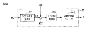
図8は、本実施形態に係るSOC制御部23の構成を示す構成図である。
FIG. 8 is a configuration diagram showing the configuration of the
SOC制御部23は、SOC目標値生成部231と、減算器232と、比例積分制御部233と、浮動充放電リミッタ234とを備えている。
The
SOC目標値生成部231には、充放電制御特性生成部22により選択された制御モードMDが入力される。SOC目標値生成部231は、制御モードMDに対応するSOC目標値S*が生成される。SOC目標値生成部231は、生成したSOC目標値S*を減算器232に出力する。
The SOC target
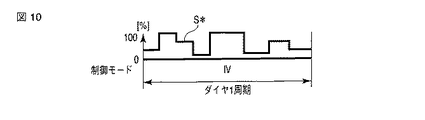
図9及び図10を参照して、制御モード1が選択されている場合のSOC目標値生成部231によるSOC目標値S*の生成について説明する。
The generation of the SOC target value S * by the SOC target
図9は、時間帯別の制御モード毎に生成されるSOC目標値S*を時系列に示すグラフ図である。図10は、ある時間帯の制御モード(制御モードIV)中のダイヤ1周期において、細分化された時間帯別に生成されるSOC目標値S*を時系列に示すグラフ図である。 FIG. 9 is a graph showing the SOC target value S * generated for each control mode for each time zone in time series. FIG. 10 is a graph showing, in time series, SOC target values S * generated for each subdivided time period in one diamond period in a certain time period control mode (control mode IV).
早朝のように回生失効し易いと予想される時間帯の制御モードの場合は、SOC目標値S*を低く設定する。ラッシュ時のように電圧降下補償が必要と予想される時間帯の制御モードの場合は、SOC目標値S*を高く設定する。また、回生失効及び電圧降下補償のいずれも予想される時間帯の制御モードの場合は、SOC目標値S*が充放電のいずれにも対応できるような中間の値(例えば、50%)に設定する。 In the case of the control mode in the time zone where the regeneration is likely to expire easily in the early morning, the SOC target value S * is set low. In a control mode in a time zone where voltage drop compensation is expected to be required as in rush hours, the SOC target value S * is set high. In addition, in the control mode in the time zone in which both regeneration expiration and voltage drop compensation are expected, the SOC target value S * is set to an intermediate value (for example, 50%) that can correspond to both charging and discharging. To do.
制御モード2が選択されている場合は、SOC目標値S*は、SOCが偏らない一定値(例えば、50%)を常に維持する。
When the
減算器232には、SOC目標値生成部231により生成されたSOC目標値S*及び蓄電装置3から受信したSOC情報Sobが入力される。減算器232は、SOC目標値S*からSOC情報Sobを減算する。減算器232は、減算した値を比例積分制御部233に出力する。
The
比例積分制御部233は、減算器232により演算されたSOC目標値S*とSOC情報Sobとの差分を零にするように比例積分制御するための演算処理をする。具体的には、比例積分制御部233は、SOC目標値S*とSOC情報Sobとの差分に基づいて、蓄電装置3の出力電流Ioutを制御するための浮動充放電制御特性の電流指令値Ifの基になる電流指令値を演算する。これにより、比例積分制御部233は、フィードバックしたSOC情報Sobに基づいて、蓄電装置3のSOCがSOC目標値S*になるように、蓄電装置3の出力電流Ioutを制御する。比例積分制御部233は、演算した電流指令値を浮動充放電リミッタ234に出力する。なお、比例積分制御部233では、リセットワインドアップ対策がされているものとする。
The proportional-plus-
浮動充放電リミッタ234は、比例積分制御部233により演算された電流指令値を、蓄電装置3の変換器から出力可能な範囲の出力電流Ioutにするための制限をする。浮動充放電リミッタ234は、制限した電流指令値を浮動充放電制御特性の電流指令値Ifとする。浮動充放電リミッタ234は、演算した浮動充放電制御特性の電流指令値Ifを充放電制御部24に出力する。
The floating charge /
充放電制御部24には、充放電制御特性生成部22により生成された屈折点パラメータPR及びSOC制御部23により演算された浮動充放電制御特性の電流指令値Ifが入力される。充放電制御部24は、屈折点パラメータPR及び浮動充放電制御特性の電流指令値Ifに基づいて、制御に用いるための充放電制御特性を決定する。また、充放電制御部24には、架線電圧Vsが入力される。充放電制御部24は、架線電圧Vs及び決定した充放電制御特性に基づいて、蓄電装置3の出力電流Ioutを制御するための電流指令値I0*を演算する。充放電制御部24は、演算した電流指令値I0*を蓄電装置保護リミッタ25に出力する。
The charge /
図5を参照して、充放電制御部24による制御を説明する。
The control by the charge /
架線電圧Vsが電圧Vaより大きく電圧Vb以下の場合、充放電制御部24は、放電方向に出力可能な最大の放電電流リミットIolimを電流指令値I0*とする。
When the overhead wire voltage Vs is greater than the voltage Va and less than or equal to the voltage Vb, the charge /
架線電圧Vsが浮動充放電制御の範囲内(電圧Vcより大きく電圧Vd以下の区間と略同程度の区間)にある場合、充放電制御部24は、浮動充放電制御特性の電流指令値Ifを電流指令値I0*とする。
When the overhead line voltage Vs is within the range of the floating charge / discharge control (a section approximately the same as the section larger than the voltage Vc and less than or equal to the voltage Vd), the charge /
架線電圧Vsが電圧Vbより大きく電圧Ve以下で、浮動充放電制御の範囲外にある場合、充放電制御部24は、架線電圧Vsに対応する放電電流Io又は充電電流Icを電流指令値I0*とする。
When the overhead wire voltage Vs is greater than the voltage Vb and less than or equal to the voltage Ve and is outside the range of the floating charge / discharge control, the charge /
架線電圧Vsが電圧Veより大きく電圧Vf以下の場合、充放電制御部24は、充電方向で最大となる充電電流リミットIclimを電流指令値I0*とする。
When the overhead wire voltage Vs is greater than the voltage Ve and equal to or less than the voltage Vf, the charge /
図11は、本実施形態に係る蓄電装置保護リミッタ25の構成を示す構成図である。
FIG. 11 is a configuration diagram illustrating a configuration of the power storage
蓄電装置保護リミッタ25は、過放電防止リミッタ251と、温度上昇抑制リミッタ252と、過電圧防止リミッタ253とを備えている。なお、ここでは、電流指令値I0*を、過放電防止リミッタ251、温度上昇抑制リミッタ252、過電圧防止リミッタ253の順に制限するように構成したが、どのような順番に制限するように構成してもよい。
The power storage
図12は、本実施形態に係る過放電防止リミッタ251の特性を示す特性図である。横軸は、蓄電装置3のSOCを示している。縦軸は、蓄電装置3の出力電流Ioutを示している。
FIG. 12 is a characteristic diagram showing characteristics of the
過放電防止リミッタ251は、蓄電装置3の寿命に大きく影響する過放電を防止するための電流リミッタである。過放電防止リミッタ251には、蓄電装置3からSOC情報Sobが入力される。過放電防止リミッタ251は、図12に示す特性により、SOC情報Sobに基づいて、充放電制御部24から出力された電流指令値I0*を制限する。
The
過放電防止リミッタ251は、SOCがa%以下のときは、放電電流リミットIolimを零にする。従って、SOCがa%以下のときは、電流指令値I0*は、放電方向に対しては零に制限される。過放電防止リミッタ251は、SOCがa%を超えるに従って、徐々に放電電流リミットIolimを最大となるまで増加させる。従って、SOCがa%を超えるに従って、電流指令値I0*は、放電方向に電流が徐々に増えるように制限される。
The
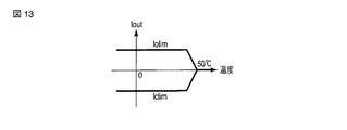
図13は、本実施形態に係る温度上昇抑制リミッタ252の特性を示す特性図である。横軸は、セル(電池)の温度Tb(例えば、全てのセルの中で最も高い温度)を示している。縦軸は、蓄電装置3の出力電流Ioutを示している。
FIG. 13 is a characteristic diagram showing the characteristics of the temperature
温度上昇抑制リミッタ252は、セルの温度Tbが規定値(例えば50度)を超過することを防止するための電流リミッタである。これは、セルの温度Tbが、蓄電装置3の寿命に大きく影響を与えるためである。温度上昇抑制リミッタ252には、蓄電装置3からセルの温度Tbが入力される。温度上昇抑制リミッタ252は、セルの温度Tbに基づいて、充放電制御部24から出力された電流指令値I0*を制限する。
The temperature rise
温度上昇抑制リミッタ252は、セルの温度Tbが50度以上になると、放電電流リミットIolim及び充電電流リミットIclimの両方を零にする。従って、セルの温度Tbが50度以上になると、電流指令値I0*は、放電方向及び充電方向の両方とも零に制限される。温度上昇抑制リミッタ252は、セルの温度Tbが50度よりも下がるに従って、徐々に放電電流リミットIolim又は充電電流リミットIclimをそれぞれ最大となるまで増加させる。従って、セルの温度Tbが50度よりも下がるに従って、電流指令値I0*は、放電方向又は充電方向のいずれの方向も出力電流Ioutが徐々に増えるように制限される。
The temperature rise
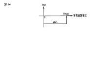
図14は、本実施形態に係る過電圧防止リミッタ253の特性を示す特性図である。
FIG. 14 is a characteristic diagram showing the characteristics of the
過電圧防止リミッタ253は、蓄電装置3の端子間電圧Vdcが規定定格電圧Vmaxを超過しないように定電圧特性を有する電流リミッタである。過電圧防止リミッタ253は、充電時に蓄電装置3の端子間電圧が上昇することにより、規定定格電圧Vmaxを超過することを防止する。過電圧防止リミッタ253には、蓄電装置3の端子間電圧Vdcが入力される。過電圧防止リミッタ253は、端子間電圧Vdcが規定定格電圧Vmaxよりも低い場合は、充電電流リミットIclimを最大にする。過電圧防止リミッタ253は、端子間電圧Vdcが規定定格電圧Vmax以上の場合は、充電電流リミットIclimを零にする。これにより、電流指令値I0*は、充電方向の出力電流Ioutが零に制限される。従って、端子間電圧Vdcが規定定格電圧Vmax以上の場合は、蓄電装置3は、充電されない。
The
図15は、本実施形態に係る蓄電システム1の列車の運用時間帯における制御モード1の充放電制御を時系列に示すグラフ図である。なお、図15に示す充放電制御は、一般的な通勤路線を例としたものである。
FIG. 15 is a graph showing time-series charge / discharge control in the
一般的な通勤路線では、早朝は列車本数が少ないため、回生失効しやすい状況にある。このため、回生失効を防止するような充放電制御特性により充放電制御を行う。 In general commuting routes, the number of trains is small in the early morning, so it is easy for regeneration to expire. For this reason, charging / discharging control is performed by the charging / discharging control characteristic which prevents regeneration expiration.
次に、朝のラッシュ時間帯に入ると、パンタ点電圧降下や、ピーク電力の問題が発生する。従って、これらの問題を解消するような充放電制御特性により充放電制御を行う。 Next, when the morning rush hour is entered, there will be problems of pant point voltage drop and peak power. Therefore, charge / discharge control is performed with charge / discharge control characteristics that eliminate these problems.
朝のラッシュ時間帯を過ぎて日中になると、列車密度が低下する。このため、列車負荷の大きさも小さくなる。従って、回生失効を防止するような充放電制御特性により充放電制御を行う。 After the morning rush hours, the train density decreases when the daytime starts. For this reason, the magnitude | size of a train load also becomes small. Therefore, charge / discharge control is performed by charge / discharge control characteristics that prevent regeneration and expiration.
夕方になると、ラッシュ時間帯が再び発生する。しかし、朝のラッシュ時間帯ほど列車密度は高くない。このため、夕方のラッシュ時間帯では、電圧降下補償及び回生失効を防止するような充放電制御特性により充放電制御を行う。 In the evening, the rush hour occurs again. However, the train density is not as high as in the morning rush hour. For this reason, in the evening rush hours, charge / discharge control is performed with charge / discharge control characteristics that prevent voltage drop compensation and regeneration expiration.
終電に近づくにつれ、運行する列車本数は低下する。このため、夕方のラッシュ時間帯以降は、回生失効を防止するような充放電制御特性により充放電制御を行う。 As the last train approaches, the number of trains operating decreases. For this reason, after the evening rush hour, charge / discharge control is performed with charge / discharge control characteristics that prevent regeneration expiration.
本実施形態によれば、以下のような作用効果を得ることができる。 According to this embodiment, the following effects can be obtained.
制御モード1では、ダイヤ情報又は隣接する変電所の回線別電流やき電線電圧などの各種情報を遠方監視制御装置等から受信することで、蓄電システム1は、周辺の負荷状態を推定することができる。このように推定された負荷状態に基づいて、充放電制御目的に適した充放電制御特性を生成する。また、電車線93の架線電圧Vs等を評価関数とした最適化アルゴリズムを実行して、充放電制御特性を生成する。これより、列車の運行状況により適した充放電制御特性を生成することができる。
In the
また、制御モード2では、閑散時又はラッシュ時などのどのような負荷状態でも常に一定の充放電効果を得られる充放電制御特性を用いて充放電制御する。一方、自立判定部21により制御モード1による充放電効果が効果的でないと判定されると、制御モード1から制御モード2に切り換わる。これにより、制御モード1で充分に充放電効果が得られない状況になっても、制御モード2に切り換わることで、蓄電システム1の充放電制御の著しい品質低下を避けることができる。
Further, in the
従って、蓄電システム1は、時間帯又は負荷状態に応じて充放電制御特性が変化する制御モード1と汎用性のある制御モード2の2種類の制御モードを設けることで、列車の運行状況に応じて効果的に電車線に充放電することができる。
Therefore, the
(第2の実施形態)
図16は、本発明の第2の実施形態に係る蓄電システム1の制御部2Aの構成を示す構成図である。
(Second Embodiment)
FIG. 16 is a configuration diagram showing the configuration of the
制御部2Aは、図2に示す第1の実施形態に係る制御部2において、充放電制御特性生成部22を充放電制御特性生成部22Aに代えた構成である。その他の構成は、第1の実施形態と同様である。
2 A of control parts are the structures which replaced the charging / discharging control characteristic production |
図17は、本実施形態に係る充放電制御特性生成部22Aの構成を示す構成図である。
FIG. 17 is a configuration diagram illustrating a configuration of the charge / discharge control
充放電制御特性生成部22Aは、図4に示す第1の実施形態に係る充放電制御特性生成部22において、屈折点パラメータ生成部222を屈折点パラメータ生成部222Aに代え、設定部STAに制御モード1Aを設定した構成である。
In the charge / discharge control
制御モード切替部221により制御モード1Aが選択された場合の屈折点パラメータ生成部222Aにおける屈折点パラメータPRAの生成について説明する。
The generation of the refraction point parameter PRA in the refraction point
図18は、本実施形態に係る屈折点パラメータ生成部222Aに設定される時系列データDTを示すデータ図である。図18は、直流1500[V]のき電システムの例を示している。
FIG. 18 is a data diagram showing time-series data DT set in the refraction point
図18に示すように、時系列に図5に示す充放電制御特性の各パラメータVa,Vb,Vc,Vd,Ve,Vf,Iolim,Iclimの設定値が予め設定されている。ここで、電圧Vaは、列車の定電圧保護セット値、電圧Vfは、回生絞り込み終了電圧とそれぞれ同値に設定されている。 As shown in FIG. 18, set values of the parameters Va, Vb, Vc, Vd, Ve, Vf, Iolim, and Icrim of the charge / discharge control characteristics shown in FIG. 5 are set in time series. Here, the voltage Va is set to the constant voltage protection set value of the train, and the voltage Vf is set to the same value as the regeneration narrowing end voltage.
屈折点パラメータ生成部222Aは、時系列データDTに従って、現在の時刻(時間帯)に対応する各パラメータVa,Vb,Vc,Vd,Ve,Vf,Iolim,Iclimの設定値を屈折点パラメータPRAとして生成する。屈折点パラメータ生成部222Aは、時系列データDTに従って決定された屈折点パラメータPRAを充放電制御部24に出力する。
The refraction point
屈折点パラメータ生成部222Aには、時刻(列車ダイヤ等)により推定される負荷状態の充放電制御目的に適した充放電制御特性になるように屈折点パラメータPRAが設定されている。よって、列車90が列車ダイヤ通りに運行されていれば、蓄電システム1の充放電制御が効果的に行われる。例えば、屈折点パラメータPRAは、図15に示す充放電制御となるように設定される。
In the refraction point
本実施形態によれば、第1の実施形態における制御モード1の代わりに、運転管理システム等からの情報を必要としない制御モード1Aを設定することにより、蓄電システム1内で完結した制御をすることができる。これにより、遠方監視制御装置と接続しなくても、第1の実施形態と同様な作用効果を得ることができる。
According to the present embodiment, in place of the
なお、各実施形態では、電気鉄道の電力系統に適用する蓄電システム1について説明したが、三相交流の電力系統に適用する構成としてもよい。例えば、蓄電システム1の負荷状態を推定して充放電を行う制御モードと、常に充電と放電のいずれも対応できるように充放電を行う制御モードとを備え、蓄電システム1の充放電による効果を判定して、これらの2つの制御モードを切り替えることで、三相交流の電力系統においても、第1の実施形態と同様の作用効果を得ることができる。また、時間帯に応じて制御目的(充電又は放電など)を変更して充放電を行う制御モードと、常に充電と放電のいずれも対応できるように充放電を行う制御モードとを備えた構成とすることで、第2の実施形態と同様の作用効果を得ることができる。
In addition, although each embodiment demonstrated the
また、各実施形態では、自立判定部21により判定に用いる指標(計画値PL及び実績値RE)として、図3に示すように、き電線入力エネルギを用いたがこれに限らない。例えば、自立判定部21が判定に用いる指標は、蓄電装置3が電車線93から充電するエネルギでもよいし、蓄電装置3の充放電電力でもよい。また、充放電実績に限らず、SOC実績で同様に評価してもよい。蓄電システム1では、図5及び図7に示すように、電圧−電流平面上で蓄電装置3の出力電流Ioutを制御するため、蓄電装置3の変換器に常時最適な電流指令値I*を与える必要はない。従って、自立判定部21は、SOC実績で評価することで、充放電計画に沿った運転ができているかを有効に判定することができる。
In each embodiment, as shown in FIG. 3, feeder input energy is used as an index (plan value PL and actual value RE) used for determination by the self-supporting
さらに、各実施形態では、2つの制御モードで蓄電装置3を充放電制御する構成としたが、3以上の制御モードを設けてもよい。また、自立判定部21は、判定結果に応じて、3以上の制御モードを選択して切り替えるようにしてもよい。
Furthermore, in each embodiment, although it was set as the structure which carries out charging / discharging control of the
また、各実施形態において、自立判定部21による充放電制御の効果を判定する方法は、説明したものに限らず、他の方法で判定してもよい。
Moreover, in each embodiment, the method of determining the effect of the charge / discharge control by the self-supporting
さらに、各実施形態において、蓄電システム1,1Aの入出電流の急激な変化を防止するために、電流の変化量を緩やかにするための電流変化量緩和部を設けてもよい。
Furthermore, in each embodiment, in order to prevent an abrupt change in the input / output current of the
また、各実施形態において、制御モード切替部221は、制御モードを切り替えた後、所定時間経過しなければ、制御モードが再度切り替わらないようにしてもよい。
In each embodiment, the control
さらに、第1の実施形態において、制御モード1の屈折点パラメータPRを演算するために用いる各種情報は、説明したものに限らない。例えば、各種情報は、変電所の整流器の運転台数、変電所で計測される出力電流若しくはき電電圧、同一のき電線(電力系統)に接続されている他の蓄電システムのSOC、又は、他の蓄電システム1が計測するき電線への入出力電流若しくはき電線電圧などでもよい。
Furthermore, in the first embodiment, various types of information used for calculating the refraction point parameter PR in the
なお、本発明のいくつかの実施形態を説明したが、これらの実施形態は、例として提示したものであり、発明の範囲を限定することは意図していない。これら新規な実施形態は、その他の様々な形態で実施されることが可能であり、発明の要旨を逸脱しない範囲で、種々の省略、置き換え、変更を行うことができる。これら実施形態やその変形は、発明の範囲や要旨に含まれるとともに、特許請求の範囲に記載された発明とその均等の範囲に含まれる。 In addition, although some embodiment of this invention was described, these embodiment is shown as an example and is not intending limiting the range of invention. These novel embodiments can be implemented in various other forms, and various omissions, replacements, and changes can be made without departing from the scope of the invention. These embodiments and modifications thereof are included in the scope and gist of the invention, and are included in the invention described in the claims and the equivalents thereof.
1…蓄電システム、2…制御部、3…蓄電装置、4…電圧検出器、5…電流検出器、10…直流電力供給システム、11…TCR、12…伝送路、90…列車、91…変圧器、92…整流器、93…電車線。
DESCRIPTION OF
Claims (11)
前記電力系統の電圧を計測する電圧計測手段と、
時間に基づいて、前記蓄電手段の充放電を制御するための第1の充放電制御特性を生成する第1の充放電制御特性生成手段と、
充電及び放電のいずれも対応するように前記蓄電手段の充放電を制御するための第2の充放電制御特性を生成する第2の充放電制御特性生成手段と、
前記第1の充放電制御特性生成手段により生成された前記第1の充放電制御特性又は前記第2の充放電制御特性生成手段により生成された前記第2の充放電制御特性を用いて、前記電圧計測手段により計測された電圧に基づいて、前記蓄電手段の充放電を制御する充放電制御手段と、
前記蓄電手段の充放電が効果的か否かを判定する判定手段と、
前記判定手段により前記蓄電手段の充放電が効果的でないと判定された場合、前記充放電制御手段に用いる充放電制御特性を切り替える充放電制御特性切替手段と
を備えたことを特徴とする蓄電システム。 Power storage means connected to the power system;
Voltage measuring means for measuring the voltage of the power system;
First charge / discharge control characteristic generating means for generating a first charge / discharge control characteristic for controlling charge / discharge of the power storage means based on time;
Second charge / discharge control characteristic generating means for generating a second charge / discharge control characteristic for controlling charge / discharge of the power storage means so as to correspond to both charging and discharging;
Using the first charge / discharge control characteristic generated by the first charge / discharge control characteristic generation means or the second charge / discharge control characteristic generated by the second charge / discharge control characteristic generation means, Charge / discharge control means for controlling charge / discharge of the power storage means based on the voltage measured by the voltage measurement means;
Determining means for determining whether charging / discharging of the power storage means is effective;
A power storage system comprising charge / discharge control characteristic switching means for switching charge / discharge control characteristics used for the charge / discharge control means when the determination means determines that charging / discharging of the power storage means is not effective. .
を特徴とする請求項1に記載の蓄電システム。 The power storage system according to claim 1, wherein the power system is an electric railway power system.
前記電力系統の電圧を計測する電圧計測手段と、
前記電力系統の負荷状態を推定するための負荷情報を取得する負荷情報取得手段と、
前記負荷情報取得手段により取得された前記負荷情報に基づいて、前記蓄電手段の充放電を制御するための第1の充放電制御特性を生成する第1の充放電制御特性生成手段と、
充電及び放電のいずれも対応するように前記蓄電手段の充放電を制御するための第2の充放電制御特性を生成する第2の充放電制御特性生成手段と、
前記第1の充放電制御特性生成手段により生成された前記第1の充放電制御特性又は前記第2の充放電制御特性生成手段により生成された前記第2の充放電制御特性を用いて、前記電圧計測手段により計測された電圧に基づいて、前記蓄電手段の充放電を制御する充放電制御手段と、
前記蓄電手段の充放電が効果的か否かを判定する判定手段と、
前記判定手段により前記蓄電手段の充放電が効果的でないと判定された場合、前記充放電制御手段に用いる充放電制御特性を切り替える充放電制御特性切替手段と
を備えたことを特徴とする蓄電システム。 Power storage means connected to the power system;
Voltage measuring means for measuring the voltage of the power system;
Load information acquisition means for acquiring load information for estimating a load state of the power system;
First charge / discharge control characteristic generation means for generating a first charge / discharge control characteristic for controlling charge / discharge of the power storage means based on the load information acquired by the load information acquisition means;
Second charge / discharge control characteristic generating means for generating a second charge / discharge control characteristic for controlling charge / discharge of the power storage means so as to correspond to both charging and discharging;
Using the first charge / discharge control characteristic generated by the first charge / discharge control characteristic generation means or the second charge / discharge control characteristic generated by the second charge / discharge control characteristic generation means, Charge / discharge control means for controlling charge / discharge of the power storage means based on the voltage measured by the voltage measurement means;
Determining means for determining whether charging / discharging of the power storage means is effective;
A power storage system comprising charge / discharge control characteristic switching means for switching charge / discharge control characteristics used for the charge / discharge control means when the determination means determines that charging / discharging of the power storage means is not effective. .
を特徴とする請求項3に記載の蓄電システム。 The power storage system according to claim 3, wherein the power system is an electric railway power system.
を特徴とする請求項4に記載の蓄電システム。 The power storage system according to claim 4, wherein the load information acquisition unit acquires an amount of electricity related to the power system as the load information.
を特徴とする請求項4に記載の蓄電システム。 The power storage system according to claim 4, wherein the load information acquisition unit acquires a charge state of another power storage unit connected to the power system as the load information.
を特徴とする請求項4に記載の蓄電システム。 The power storage system according to claim 4, wherein the load information acquisition unit acquires information relating to a train schedule as the load information.
を特徴とする請求項1から請求項7のいずれか1項に記載の蓄電システム。 The power storage system according to any one of claims 1 to 7, wherein the determination unit makes a determination based on a comparison between an amount of electricity of the power storage unit and a past actual value.
を特徴とする請求項1から請求項7のいずれか1項に記載の蓄電システム。 The power storage system according to any one of claims 1 to 7, wherein the determination unit determines based on a comparison between a charged state of the power storage unit and a target charged state.
前記電力系統の電圧を計測し、
時間に基づいて、前記蓄電装置の充放電を制御するための第1の充放電制御特性を生成し、
充電及び放電のいずれも対応するように前記蓄電装置の充放電を制御するための第2の充放電制御特性を生成し、
生成した前記第1の充放電制御特性又は生成した前記第2の充放電制御特性を用いて、計測した電圧に基づいて、前記蓄電装置の充放電を制御し、
前記蓄電装置の充放電が効果的か否かを判定し、
前記蓄電装置の充放電が効果的でないと判定した場合、前記蓄電装置の制御に用いる充放電制御特性を切り替えること
を特徴とする蓄電装置の制御方法。 A control method for controlling a power storage device connected to an electric power system,
Measure the voltage of the power system,
Based on the time, a first charge / discharge control characteristic for controlling charge / discharge of the power storage device is generated,
Generating a second charge / discharge control characteristic for controlling charge / discharge of the power storage device so that both charge and discharge are supported;
Based on the measured voltage using the generated first charge / discharge control characteristic or the generated second charge / discharge control characteristic, the charge / discharge of the power storage device is controlled,
Determine whether charging and discharging of the power storage device is effective,
A method for controlling a power storage device, comprising: switching charge / discharge control characteristics used for controlling the power storage device when it is determined that charging / discharging of the power storage device is not effective.
前記電力系統の電圧を計測し、
前記電力系統の負荷状態を推定するための負荷情報を取得し、
取得した前記負荷情報に基づいて、前記蓄電手段の充放電を制御するための第1の充放電制御特性を生成し、
充電及び放電のいずれも対応するように前記蓄電装置の充放電を制御するための第2の充放電制御特性を生成し、
生成した前記第1の充放電制御特性又は生成した前記第2の充放電制御特性を用いて、計測した電圧に基づいて、前記蓄電装置の充放電を制御し、
前記蓄電装置の充放電が効果的か否かを判定し、
前記蓄電装置の充放電が効果的でないと判定した場合、前記蓄電装置の制御に用いる充放電制御特性を切り替えること
を特徴とする蓄電装置の制御方法。 A control method for controlling a power storage device connected to an electric power system,
Measure the voltage of the power system,
Obtaining load information for estimating a load state of the power system;
Based on the acquired load information, a first charge / discharge control characteristic for controlling charge / discharge of the power storage means is generated,
Generating a second charge / discharge control characteristic for controlling charge / discharge of the power storage device so that both charge and discharge are supported;
Based on the measured voltage using the generated first charge / discharge control characteristic or the generated second charge / discharge control characteristic, the charge / discharge of the power storage device is controlled,
Determine whether charging and discharging of the power storage device is effective,
A method for controlling a power storage device, comprising: switching charge / discharge control characteristics used for controlling the power storage device when it is determined that charging / discharging of the power storage device is not effective.
Priority Applications (1)
| Application Number | Priority Date | Filing Date | Title |
|---|---|---|---|
| JP2010250047A JP2012105407A (en) | 2010-11-08 | 2010-11-08 | Power storage system |
Applications Claiming Priority (1)
| Application Number | Priority Date | Filing Date | Title |
|---|---|---|---|
| JP2010250047A JP2012105407A (en) | 2010-11-08 | 2010-11-08 | Power storage system |
Publications (1)
| Publication Number | Publication Date |
|---|---|
| JP2012105407A true JP2012105407A (en) | 2012-05-31 |
Family
ID=46395142
Family Applications (1)
| Application Number | Title | Priority Date | Filing Date |
|---|---|---|---|
| JP2010250047A Pending JP2012105407A (en) | 2010-11-08 | 2010-11-08 | Power storage system |
Country Status (1)
| Country | Link |
|---|---|
| JP (1) | JP2012105407A (en) |
Cited By (18)
| Publication number | Priority date | Publication date | Assignee | Title |
|---|---|---|---|---|
| WO2014049893A1 (en) * | 2012-09-28 | 2014-04-03 | 株式会社 東芝 | Railway power management device, railway power management method, and railway power management program |
| WO2014068815A1 (en) * | 2012-10-31 | 2014-05-08 | 株式会社 東芝 | Power management device and power management system |
| JP2014088157A (en) * | 2012-10-31 | 2014-05-15 | Toshiba Corp | Power management device |
| JP2014104935A (en) * | 2012-11-29 | 2014-06-09 | Toshiba Corp | Power management system and power management device |
| JP2014121246A (en) * | 2012-12-19 | 2014-06-30 | Mitsubishi Heavy Ind Ltd | Charging/discharging control device, charging/discharging control method, program, and vehicle traffic system |
| JP2014117993A (en) * | 2012-12-14 | 2014-06-30 | Hitachi Ltd | Power converter and method for controlling power converter |
| JP2014184911A (en) * | 2013-03-25 | 2014-10-02 | Railway Technical Research Institute | Dc substation for railroad |
| JP2015024689A (en) * | 2013-07-24 | 2015-02-05 | 株式会社東芝 | Controller |
| US20150045997A1 (en) * | 2013-08-12 | 2015-02-12 | Kabushiki Kaisha Toshiba | Electric railcar power feeding system, power feeding device, and power storage device |
| JP2015047893A (en) * | 2013-08-30 | 2015-03-16 | 三菱電機株式会社 | Ground battery control device and control method thereof, and ground battery control system for railway |
| JP2015107699A (en) * | 2013-12-03 | 2015-06-11 | 株式会社東芝 | Dc power supply system |
| JP2016078800A (en) * | 2014-10-22 | 2016-05-16 | 三菱電機株式会社 | Storage battery charge/discharge management apparatus and storage battery charge/discharge management system |
| US9634505B2 (en) | 2012-11-28 | 2017-04-25 | Mitsubishi Heavy Industries, Ltd. | Charging and discharging control device, charging and discharging control system, charging and discharging control method, and program |
| JP2017140908A (en) * | 2016-02-09 | 2017-08-17 | 株式会社東芝 | Power storage device and power storage method |
| EP3210820A4 (en) * | 2014-10-21 | 2018-06-06 | Kabushiki Kaisha Toshiba | Power storage device |
| JP2019018824A (en) * | 2017-07-21 | 2019-02-07 | 株式会社日立製作所 | Control device and method for railroad system |
| US20200198472A1 (en) * | 2017-05-04 | 2020-06-25 | Cummins Inc. | Systems and methods for hybrid electric vehicle battery state of charge reference scheduling |
| CN114407734A (en) * | 2021-12-21 | 2022-04-29 | 西南交通大学 | Flexible traction power supply system and protection method |
-
2010
- 2010-11-08 JP JP2010250047A patent/JP2012105407A/en active Pending
Cited By (25)
| Publication number | Priority date | Publication date | Assignee | Title |
|---|---|---|---|---|
| EP2903128A4 (en) * | 2012-09-28 | 2016-07-27 | Toshiba Kk | Railway power management device, railway power management method, and railway power management program |
| JP2014073014A (en) * | 2012-09-28 | 2014-04-21 | Toshiba Corp | Railway power management device |
| CN104170208B (en) * | 2012-09-28 | 2017-12-15 | 株式会社东芝 | Railway electrical management device, railway electric power management method and railway electrical management program |
| WO2014049893A1 (en) * | 2012-09-28 | 2014-04-03 | 株式会社 東芝 | Railway power management device, railway power management method, and railway power management program |
| US9764649B2 (en) | 2012-09-28 | 2017-09-19 | Kabushiki Kaisha Toshiba | Power management apparatus, power management method and power management program |
| CN104170208A (en) * | 2012-09-28 | 2014-11-26 | 株式会社东芝 | Railway power management device, railway power management method, and railway power management program |
| WO2014068815A1 (en) * | 2012-10-31 | 2014-05-08 | 株式会社 東芝 | Power management device and power management system |
| JP2014088157A (en) * | 2012-10-31 | 2014-05-15 | Toshiba Corp | Power management device |
| US9634505B2 (en) | 2012-11-28 | 2017-04-25 | Mitsubishi Heavy Industries, Ltd. | Charging and discharging control device, charging and discharging control system, charging and discharging control method, and program |
| JP2014104935A (en) * | 2012-11-29 | 2014-06-09 | Toshiba Corp | Power management system and power management device |
| JP2014117993A (en) * | 2012-12-14 | 2014-06-30 | Hitachi Ltd | Power converter and method for controlling power converter |
| JP2014121246A (en) * | 2012-12-19 | 2014-06-30 | Mitsubishi Heavy Ind Ltd | Charging/discharging control device, charging/discharging control method, program, and vehicle traffic system |
| US9738173B2 (en) | 2012-12-19 | 2017-08-22 | Mitsubishi Heavy Industries, Ltd. | Charging and discharging control device, charging and discharging control method, program and vehicle traffic system |
| JP2014184911A (en) * | 2013-03-25 | 2014-10-02 | Railway Technical Research Institute | Dc substation for railroad |
| JP2015024689A (en) * | 2013-07-24 | 2015-02-05 | 株式会社東芝 | Controller |
| US20150045997A1 (en) * | 2013-08-12 | 2015-02-12 | Kabushiki Kaisha Toshiba | Electric railcar power feeding system, power feeding device, and power storage device |
| US9873335B2 (en) * | 2013-08-12 | 2018-01-23 | Kabushiki Kaisha Toshiba | Electric railcar power feeding system, power feeding device, and power storage device |
| JP2015047893A (en) * | 2013-08-30 | 2015-03-16 | 三菱電機株式会社 | Ground battery control device and control method thereof, and ground battery control system for railway |
| JP2015107699A (en) * | 2013-12-03 | 2015-06-11 | 株式会社東芝 | Dc power supply system |
| EP3210820A4 (en) * | 2014-10-21 | 2018-06-06 | Kabushiki Kaisha Toshiba | Power storage device |
| JP2016078800A (en) * | 2014-10-22 | 2016-05-16 | 三菱電機株式会社 | Storage battery charge/discharge management apparatus and storage battery charge/discharge management system |
| JP2017140908A (en) * | 2016-02-09 | 2017-08-17 | 株式会社東芝 | Power storage device and power storage method |
| US20200198472A1 (en) * | 2017-05-04 | 2020-06-25 | Cummins Inc. | Systems and methods for hybrid electric vehicle battery state of charge reference scheduling |
| JP2019018824A (en) * | 2017-07-21 | 2019-02-07 | 株式会社日立製作所 | Control device and method for railroad system |
| CN114407734A (en) * | 2021-12-21 | 2022-04-29 | 西南交通大学 | Flexible traction power supply system and protection method |
Similar Documents
| Publication | Publication Date | Title |
|---|---|---|
| JP2012105407A (en) | Power storage system | |
| JP5677161B2 (en) | Charge / discharge determination device and program | |
| JP5663645B2 (en) | Control apparatus and control method | |
| JP5695464B2 (en) | Charge / discharge determination device and charge / discharge determination program | |
| JP5583781B2 (en) | Power management system | |
| KR101489629B1 (en) | Power control device and power control method | |
| JP6635742B2 (en) | Storage battery maintenance device and storage battery maintenance method | |
| CN105051999A (en) | Method and device for regulating the charge state of a battery power plant | |
| JP2012039821A (en) | Power fluctuation relaxing device of power generating system and power fluctuation relaxing method | |
| CN103795104A (en) | Power storage system and power source system | |
| US10749346B2 (en) | Power management system | |
| KR20160064973A (en) | Power stabilizing system and method for power generated by renewable energy | |
| JP2012257365A (en) | Charging/discharging method of storage battery | |
| JP6356517B2 (en) | System monitoring and control device | |
| JP2013141374A (en) | Electric power supply system for electric railroad | |
| JPWO2019230783A1 (en) | Device management server, device management system and device management method | |
| JP2015134523A (en) | Electric railroad power control system and method | |
| JPWO2018003581A1 (en) | Power storage system | |
| JP2014138534A (en) | Power control unit, power control system, and power control method | |
| JP6960314B2 (en) | Power management system | |
| KR102081780B1 (en) | Energy management system for multi-battery | |
| JP2015024689A (en) | Controller | |
| JP2014168343A (en) | Power storage system, controller of power storage system, control method of power storage system, and control program of power storage system | |
| JP6054442B2 (en) | Elevator control device | |
| TWI823260B (en) | Instruction device, charge-discharge control system, power control system, central instruction device, setting value management device, charge-discharge control method and recording medium |
Legal Events
| Date | Code | Title | Description |
|---|---|---|---|
| A621 | Written request for application examination |
Free format text: JAPANESE INTERMEDIATE CODE: A621 Effective date: 20131101 |
|
| RD04 | Notification of resignation of power of attorney |
Free format text: JAPANESE INTERMEDIATE CODE: A7424 Effective date: 20131205 |
|
| RD04 | Notification of resignation of power of attorney |
Free format text: JAPANESE INTERMEDIATE CODE: A7424 Effective date: 20131212 |
|
| RD04 | Notification of resignation of power of attorney |
Free format text: JAPANESE INTERMEDIATE CODE: A7424 Effective date: 20131219 |
|
| RD04 | Notification of resignation of power of attorney |
Free format text: JAPANESE INTERMEDIATE CODE: A7424 Effective date: 20131226 |
|
| RD04 | Notification of resignation of power of attorney |
Free format text: JAPANESE INTERMEDIATE CODE: A7424 Effective date: 20140109 |
|
| RD04 | Notification of resignation of power of attorney |
Free format text: JAPANESE INTERMEDIATE CODE: A7424 Effective date: 20140116 |
|
| A977 | Report on retrieval |
Free format text: JAPANESE INTERMEDIATE CODE: A971007 Effective date: 20140722 |
|
| A131 | Notification of reasons for refusal |
Free format text: JAPANESE INTERMEDIATE CODE: A131 Effective date: 20140805 |
|
| A02 | Decision of refusal |
Free format text: JAPANESE INTERMEDIATE CODE: A02 Effective date: 20141202 |