JP2012104375A - Display device and backlight device - Google Patents
Display device and backlight device Download PDFInfo
- Publication number
- JP2012104375A JP2012104375A JP2010252008A JP2010252008A JP2012104375A JP 2012104375 A JP2012104375 A JP 2012104375A JP 2010252008 A JP2010252008 A JP 2010252008A JP 2010252008 A JP2010252008 A JP 2010252008A JP 2012104375 A JP2012104375 A JP 2012104375A
- Authority
- JP
- Japan
- Prior art keywords
- light source
- substrate
- diffusion state
- line
- line light
- Prior art date
- Legal status (The legal status is an assumption and is not a legal conclusion. Google has not performed a legal analysis and makes no representation as to the accuracy of the status listed.)
- Pending
Links
Images


Classifications
-
- G—PHYSICS
- G02—OPTICS
- G02F—OPTICAL DEVICES OR ARRANGEMENTS FOR THE CONTROL OF LIGHT BY MODIFICATION OF THE OPTICAL PROPERTIES OF THE MEDIA OF THE ELEMENTS INVOLVED THEREIN; NON-LINEAR OPTICS; FREQUENCY-CHANGING OF LIGHT; OPTICAL LOGIC ELEMENTS; OPTICAL ANALOGUE/DIGITAL CONVERTERS
- G02F1/00—Devices or arrangements for the control of the intensity, colour, phase, polarisation or direction of light arriving from an independent light source, e.g. switching, gating or modulating; Non-linear optics
- G02F1/01—Devices or arrangements for the control of the intensity, colour, phase, polarisation or direction of light arriving from an independent light source, e.g. switching, gating or modulating; Non-linear optics for the control of the intensity, phase, polarisation or colour
- G02F1/13—Devices or arrangements for the control of the intensity, colour, phase, polarisation or direction of light arriving from an independent light source, e.g. switching, gating or modulating; Non-linear optics for the control of the intensity, phase, polarisation or colour based on liquid crystals, e.g. single liquid crystal display cells
- G02F1/133—Constructional arrangements; Operation of liquid crystal cells; Circuit arrangements
- G02F1/1333—Constructional arrangements; Manufacturing methods
- G02F1/1347—Arrangement of liquid crystal layers or cells in which the final condition of one light beam is achieved by the addition of the effects of two or more layers or cells
- G02F1/13476—Arrangement of liquid crystal layers or cells in which the final condition of one light beam is achieved by the addition of the effects of two or more layers or cells in which at least one liquid crystal cell or layer assumes a scattering state
-
- G—PHYSICS
- G02—OPTICS
- G02B—OPTICAL ELEMENTS, SYSTEMS OR APPARATUS
- G02B30/00—Optical systems or apparatus for producing three-dimensional [3D] effects, e.g. stereoscopic images
- G02B30/20—Optical systems or apparatus for producing three-dimensional [3D] effects, e.g. stereoscopic images by providing first and second parallax images to an observer's left and right eyes
- G02B30/26—Optical systems or apparatus for producing three-dimensional [3D] effects, e.g. stereoscopic images by providing first and second parallax images to an observer's left and right eyes of the autostereoscopic type
- G02B30/27—Optical systems or apparatus for producing three-dimensional [3D] effects, e.g. stereoscopic images by providing first and second parallax images to an observer's left and right eyes of the autostereoscopic type involving lenticular arrays
-
- G—PHYSICS
- G02—OPTICS
- G02B—OPTICAL ELEMENTS, SYSTEMS OR APPARATUS
- G02B30/00—Optical systems or apparatus for producing three-dimensional [3D] effects, e.g. stereoscopic images
- G02B30/20—Optical systems or apparatus for producing three-dimensional [3D] effects, e.g. stereoscopic images by providing first and second parallax images to an observer's left and right eyes
- G02B30/26—Optical systems or apparatus for producing three-dimensional [3D] effects, e.g. stereoscopic images by providing first and second parallax images to an observer's left and right eyes of the autostereoscopic type
- G02B30/33—Optical systems or apparatus for producing three-dimensional [3D] effects, e.g. stereoscopic images by providing first and second parallax images to an observer's left and right eyes of the autostereoscopic type involving directional light or back-light sources
-
- G—PHYSICS
- G02—OPTICS
- G02F—OPTICAL DEVICES OR ARRANGEMENTS FOR THE CONTROL OF LIGHT BY MODIFICATION OF THE OPTICAL PROPERTIES OF THE MEDIA OF THE ELEMENTS INVOLVED THEREIN; NON-LINEAR OPTICS; FREQUENCY-CHANGING OF LIGHT; OPTICAL LOGIC ELEMENTS; OPTICAL ANALOGUE/DIGITAL CONVERTERS
- G02F1/00—Devices or arrangements for the control of the intensity, colour, phase, polarisation or direction of light arriving from an independent light source, e.g. switching, gating or modulating; Non-linear optics
- G02F1/01—Devices or arrangements for the control of the intensity, colour, phase, polarisation or direction of light arriving from an independent light source, e.g. switching, gating or modulating; Non-linear optics for the control of the intensity, phase, polarisation or colour
- G02F1/13—Devices or arrangements for the control of the intensity, colour, phase, polarisation or direction of light arriving from an independent light source, e.g. switching, gating or modulating; Non-linear optics for the control of the intensity, phase, polarisation or colour based on liquid crystals, e.g. single liquid crystal display cells
- G02F1/133—Constructional arrangements; Operation of liquid crystal cells; Circuit arrangements
- G02F1/1333—Constructional arrangements; Manufacturing methods
- G02F1/1335—Structural association of cells with optical devices, e.g. polarisers or reflectors
- G02F1/1336—Illuminating devices
- G02F1/133602—Direct backlight
- G02F1/133606—Direct backlight including a specially adapted diffusing, scattering or light controlling members
-
- H—ELECTRICITY
- H04—ELECTRIC COMMUNICATION TECHNIQUE
- H04N—PICTORIAL COMMUNICATION, e.g. TELEVISION
- H04N13/00—Stereoscopic video systems; Multi-view video systems; Details thereof
- H04N13/30—Image reproducers
- H04N13/302—Image reproducers for viewing without the aid of special glasses, i.e. using autostereoscopic displays
- H04N13/31—Image reproducers for viewing without the aid of special glasses, i.e. using autostereoscopic displays using parallax barriers
- H04N13/312—Image reproducers for viewing without the aid of special glasses, i.e. using autostereoscopic displays using parallax barriers the parallax barriers being placed behind the display panel, e.g. between backlight and spatial light modulator [SLM]
-
- H—ELECTRICITY
- H04—ELECTRIC COMMUNICATION TECHNIQUE
- H04N—PICTORIAL COMMUNICATION, e.g. TELEVISION
- H04N13/00—Stereoscopic video systems; Multi-view video systems; Details thereof
- H04N13/30—Image reproducers
- H04N13/302—Image reproducers for viewing without the aid of special glasses, i.e. using autostereoscopic displays
- H04N13/32—Image reproducers for viewing without the aid of special glasses, i.e. using autostereoscopic displays using arrays of controllable light sources; using moving apertures or moving light sources
-
- H—ELECTRICITY
- H04—ELECTRIC COMMUNICATION TECHNIQUE
- H04N—PICTORIAL COMMUNICATION, e.g. TELEVISION
- H04N13/00—Stereoscopic video systems; Multi-view video systems; Details thereof
- H04N13/30—Image reproducers
- H04N13/349—Multi-view displays for displaying three or more geometrical viewpoints without viewer tracking
-
- H—ELECTRICITY
- H04—ELECTRIC COMMUNICATION TECHNIQUE
- H04N—PICTORIAL COMMUNICATION, e.g. TELEVISION
- H04N13/00—Stereoscopic video systems; Multi-view video systems; Details thereof
- H04N13/30—Image reproducers
- H04N13/356—Image reproducers having separate monoscopic and stereoscopic modes
- H04N13/359—Switching between monoscopic and stereoscopic modes
-
- G—PHYSICS
- G02—OPTICS
- G02B—OPTICAL ELEMENTS, SYSTEMS OR APPARATUS
- G02B30/00—Optical systems or apparatus for producing three-dimensional [3D] effects, e.g. stereoscopic images
- G02B30/20—Optical systems or apparatus for producing three-dimensional [3D] effects, e.g. stereoscopic images by providing first and second parallax images to an observer's left and right eyes
- G02B30/26—Optical systems or apparatus for producing three-dimensional [3D] effects, e.g. stereoscopic images by providing first and second parallax images to an observer's left and right eyes of the autostereoscopic type
- G02B30/27—Optical systems or apparatus for producing three-dimensional [3D] effects, e.g. stereoscopic images by providing first and second parallax images to an observer's left and right eyes of the autostereoscopic type involving lenticular arrays
- G02B30/29—Optical systems or apparatus for producing three-dimensional [3D] effects, e.g. stereoscopic images by providing first and second parallax images to an observer's left and right eyes of the autostereoscopic type involving lenticular arrays characterised by the geometry of the lenticular array, e.g. slanted arrays, irregular arrays or arrays of varying shape or size
Landscapes
- Physics & Mathematics (AREA)
- Nonlinear Science (AREA)
- Multimedia (AREA)
- Signal Processing (AREA)
- Engineering & Computer Science (AREA)
- Optics & Photonics (AREA)
- General Physics & Mathematics (AREA)
- Crystallography & Structural Chemistry (AREA)
- Chemical & Material Sciences (AREA)
- Mathematical Physics (AREA)
- Liquid Crystal (AREA)
- Planar Illumination Modules (AREA)
- Testing, Inspecting, Measuring Of Stereoscopic Televisions And Televisions (AREA)
Abstract
Description
本発明の実施形態は、表示装置およびバックライト装置に関する。 Embodiments described herein relate generally to a display device and a backlight device.
専用の眼鏡等を必要としない立体視画像表示方式には種々の方式が知られている。直視型や投影型の液晶表示装置、或いはプラズマ表示装置等のような表示パネルは、画素位置が固定されている。このような表示パネルでは、表示パネルの直前に表示パネルからの光線を制御して観察者に向ける光線制御素子を設置する方式が比較的容易に実現できる方式として知られている。 Various methods are known as a stereoscopic image display method that does not require dedicated glasses or the like. In a display panel such as a direct-view or projection-type liquid crystal display device or a plasma display device, the pixel position is fixed. In such a display panel, a system in which a light beam control element that controls a light beam from the display panel and directs it to an observer immediately before the display panel is known as a method that can be realized relatively easily.
光線制御素子は、一般的には、パララックスバリア(視差バリア)とも称せられ、光線制御素子上の同一位置でも角度により異なる画像が見えるように光線を制御している。具体的には、左右視差(水平視差)のみを与える場合には、光線制御素子としてスリット或いはレンチキュラシート(シリンドリカルレンズアレイ)が用いられる。上下視差(垂直視差)も含める場合には、光線制御素子としてピンホールアレイ或いはレンズアレイが用いられる。更に、視差バリアを用いる方式は、2 眼式、多眼式、超多眼式(多眼式の超多眼条件)、及びインテグラルフォトグラフィ(IP)に分類される。これらの基本的な原理は、100年程度前に発明され、立体写真に用いられてきたものと実質上同一である。 The light beam control element is generally called a parallax barrier, and controls light beams so that different images can be seen depending on the angle even at the same position on the light beam control element. Specifically, when only the right and left parallax (horizontal parallax) is given, a slit or a lenticular sheet (cylindrical lens array) is used as the light beam control element. When including vertical parallax (vertical parallax), a pinhole array or a lens array is used as a light beam control element. Furthermore, methods using a parallax barrier are classified into binocular, multi-view, super multi-view (multi-view super multi-view conditions), and integral photography (IP). These basic principles are substantially the same as those invented about 100 years ago and used for stereoscopic photography.
近年、パソコン用途やテレビ用途等で、2次元画像と3次元画像の切替え表示が必須機能になりつつある。2次元画像と3次元画像の切替えを実現する手法としては、レンズ背面に線光源を複数設置し、線光源の個別点灯と全点灯を切替えて2次元画像と3次元画像の表示を行なう方法や、面光源上にバリアと高分散型液晶を設置し、電気的に拡散状態のON/OFFを行い、2次元画像と3次元画像の表示を行う方法や、マトリックスやストライプ状にパターンニングされた面光源とレンチキュラシートの前面に拡散状態切替え素子を設置し、拡散状態のON/OFFを行う方法が開示されている。しかし、上記の従来技術では、画質と光利用効率を両立することが困難であった。 In recent years, switching display between a two-dimensional image and a three-dimensional image has become an essential function for personal computer use, television use, and the like. As a method for realizing switching between a two-dimensional image and a three-dimensional image, a method of displaying a two-dimensional image and a three-dimensional image by installing a plurality of line light sources on the rear surface of the lens and switching between individual lighting and full lighting of the line light sources, , A barrier and high-dispersion type liquid crystal are installed on the surface light source, electrically turned on / off in a diffused state, and displayed in 2D and 3D images, or patterned in a matrix or stripe form A method is disclosed in which a diffusion state switching element is installed in front of a surface light source and a lenticular sheet, and the diffusion state is turned ON / OFF. However, with the above-described conventional technology, it has been difficult to achieve both image quality and light utilization efficiency.
本発明が解決しようとする課題は、2次元画像と3次元画像の切替えを行っても画質の低下及び光利用効率の低下を抑制することができる表示装置およびこの表示装置に用いられるバックライト装置を提供することである。 A problem to be solved by the present invention is a display device capable of suppressing deterioration in image quality and light utilization efficiency even when switching between a two-dimensional image and a three-dimensional image, and a backlight device used in the display device Is to provide.
本実施形態のバックライト装置は、互いに並列に配列された複数の光学的開口を有する光学的開口部と、前記光学的開口のそれぞれに対応して設けられた線状の光を発生する少なくとも1個の線光源を有し、それぞれの線光源が互いに並列に配列された線光源装置と、前記光学的開口のそれぞれに対応する領域において、前記線光源装置からの光の拡散状態を切り替えることが可能な拡散状態切替え素子と、を備えたことを特徴とする。 The backlight device according to the present embodiment has at least one optical aperture having a plurality of optical apertures arranged in parallel to each other and linear light provided corresponding to each of the optical apertures. A line light source device having a plurality of line light sources, and the line light source devices arranged in parallel with each other, and a diffusion state of light from the line light source device in a region corresponding to each of the optical apertures. And a possible diffusion state switching element.
以下に図面を参照して本発明の実施形態について説明する。 Embodiments of the present invention will be described below with reference to the drawings.
(第1実施形態)
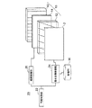
第1実施形態による表示装置を図1に示す。この実施形態の表示装置は、表示パネル2と、バックライト装置10と、を備えている。このバックライト装置10は、指向性の光を発生することのできるバックライト装置であって、表示パネル2の列方向に平行に配列された複数の光学的開口を有する光学的開口部(光線制御部)12と、拡散状態が電気的に複数切替えられる拡散状態切替え素子14と、各光学的開口に対応して設けられた線状の光を発生する少なくとも1個の線光源を有する線光源装置16と、を備えている。なお、本実施形態においては、表示パネル2の背面側、すなわち図示しない視聴者に対向する面と反対側の面の側にバックライト装置10が設けられる。そして、表示パネル2と線光源装置16との間に光学的開口部12が設けられ、線光源装置16と光学的開口部12との間に拡散状態切替え素子14が設けられる。なお、図2に示す第1変形例のような構成であってもよい。この第1変形例においては、第1実施形態のバックライト装置10をバックライト装置10Aで置き換えた構成を有している。この第1変形例のバックライト装置10Aは、バックライト装置10とは、拡散状態切替え素子14の配置が異なっており、この拡散状態切替え素子14を、表示パネル2と、光学的開口部12との間に設けた構成となっている。なお、後述する各変形例の表示装置においても、第1変形例と同様に、拡散状態切替え素子14を、表示パネル2と、光学的開口部12との間に設けた構成としてもよい。
(First embodiment)
A display device according to the first embodiment is shown in FIG. The display device of this embodiment includes a
光学的開口部12は、本実施形態においては、水平視差を与えるパララックスバリアであって、レンチキュラシート(シリンドリカルレンズアレイ)、或いは複数のスリットを有するスリット板が用いられる。すなわち、シリンドリカルレンズアレイである場合は各シリンドカルレンズが光学的開口であり、スリット板である場合は各スリットが光学的開口となる。図1では、光学的開口部12としてシリンドリカルレンズアレイを示している。
In the present embodiment, the
拡散状態切替え素子14は、後述する拡散制御部によって複数の拡散状態に切り替えられ、光学的開口部12の1ピッチに対応する領域内に1つ或いは複数の拡散状態が生成される。この拡散状態切替え素子14は、2つの制御電極間に、例えば、高分子分散型液晶か、または液晶中に高分子がネットワーク上に形成された構造が設けられており、上記2つの制御電極間に電圧を印加した状態では液晶の配向が揃い透明になり、電圧を印加しない状態では液晶が不規則に並んで拡散状態になって白濁する。この拡散状態は電気的に白濁の割合を変化させることができる。ここで、拡散状態切替え素子14の拡散状態は、ヘーズ値(=(拡散状態における透過率)/(全光透過率) ×100)で表され、ヘーズ値が大きいほど拡散し、白濁度合いが大きい。
The diffusion
線光源装置16は、LEDおよび直線状に光を取り出す導光板を備えた構造を有するか、またはプラズマ発生素子や有機ELなどといった自発光素子などを備えている。なお、拡散状態切替え素子14の位置は光学的開口部12の背面、すなわち光学的開口部12と線光源装置16との間に設置した場合、製造時に線光源装置16の線光源自体の幅を変化させなくても、拡散状態を変化させて光学的開口部12に到達する光線幅を変化さることが可能になる。
The line
図3(a)、3(b)、3(c)に光学的開口部12の背面に設置される線光源装置16によって生成された輝度プロファイル例を示す。一般には光学的開口部12の中央付近は鋭いピークのプロファイルになり高輝度であるが、周辺部ほど輝度が下がり、輝度差が生じる。この場合、図3(a)に示すように、中央付近には狭いピーク幅が存在し、目に感じる視野角特性が悪くなる。これに対して、図3(b)に示すように光学的開口部12の中央付近の拡散状態を、拡散状態切替え素子14によって増加させると、図3(c)に示すようにピーク幅が広い視野角特性に近づけることができる。拡散状態を光学的開口部12の各ピッチに対応する領域内に分布を持たせるには、拡散状態切替え素子14における、光学的開口部12の各ピッチに対応する領域内に透明電極を複数個、設置すれば良い。
3A, 3B, and 3C show examples of luminance profiles generated by the line
また、図4に示すように、本実施形態の表示装置には、制御部20と、記憶部30とが設けられている。制御部20は、同期制御部22と、表示画像制御部24と、拡散制御部26とを有している。同期制御部22は、表示画像制御部24の制御動作と、拡散制御部26の制御動作とが同期するように制御する。記憶部30は外部から送られてくる画像データを記憶する。表示画像制御部24は、記憶部30に記憶された画像データを、画像表示モードに応じて、表示パネル2に送り表示画像の制御を行う。例えば、記憶部30に記憶された画像データが2次元画像データである場合には、そのまま表示パネル2に送り表示させる。記憶部30に記憶された画像データが3次元画像データである場合には、多視差画像(例えば、9視差画像)に変換し、この多視差画像を光学的開口部12の開口部毎に各視差画像の構成要素である画素を並び替えて3次元画像表示用の画像を作成し、表示パネル2に送る。なお、各視差画像が3個のサブ画素(例えば、R(赤)、G(緑)、B(青)から構成されている場合には、画素単位の情報をサブ画素単位で並び替える処理を行ってから3次元画像表示用の画像を生成する。また、特開2006−98779号公報に示すように、視差画像のうち実際に必要な部分のみをまとめることにより、視差画像の伝送や圧縮に向くフォーマット(例えば、タイル画像)に変換してもよい。拡散制御部26は、画像表示モード(2次元画像表示モード或いは3次元画像表示モード)と、後述する線光源の点灯モードとによって、拡散状態切替え素子14の拡散状態を電気的に切替える制御を行う。
As shown in FIG. 4, the display device of the present embodiment is provided with a
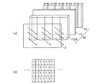
また、図5(a)、5(b)に示す第2変形例および第3変形例のように、バックライト装置を構成してもよい。図5(a)に示す第2変形例におけるバックライト装置10Bは、光学的開口部12と、拡散状態切替え素子14と、線光源装置16Aとを備えている。光学的開口部12は、図1に示す第1実施形態の光学的開口部12と同一の構成を有しており、開口、例えばレンチキュラーレンズの稜線が列方向に対して傾いた構成となっている。拡散状態切替え素子14は図1に示す第1実施形態の拡散状態切替え素子14と同一の構成を有している。線光源装置16Aは、線光源の数が光学的開口部12の各開口に対して1個設けられた構成となっており、各光源は列方向に延在している。すなわち、線光源装置16Aの光源と、光学的開口部12のレンチキュラーレンズの稜線とは、ある傾き角θを成している構成となっている。この傾き角θは、nを2以上の正の整数としたとき、
θ=tan−1(pL/(n×psub))
であることが好ましい。ここで、pLはレンズピッチ、psubは表示パネル2の1つのサブ画素幅を表す。
Moreover, you may comprise a backlight apparatus like the 2nd modification and 3rd modification shown to Fig.5 (a) and 5 (b). The
θ = tan −1 (p L / (n × p sub ))
It is preferable that Here, p L represents the lens pitch, and p sub represents one sub-pixel width of the
また、図5(b)に示す第3変形例におけるバックライト装置10Cは、光学的開口部12Aと、拡散状態切替え素子14と、線光源16Bとを備えている。光学的開口部12Aは、図1に示す第1実施形態の光学的開口部12と異なり、開口、例えばレンチキュラーレンズの稜線が列方向に沿って配置された構成となっている。拡散状態切替え素子14は図1に示す第1実施形態の拡散状態切替え素子14と同一の構成を有している。線光源装置16Bは、光源の数が光学的開口部12Aの各開口に対して1個設けられた構成となっており、各光源は列方向に対して傾いた構成となっている。すなわち、線光源16Bの光源と、光学的開口部12Aのレンチキュラーレンズの稜線とは、ある傾き角θを成している構成となっている。この傾き角θは、nを2以上の正の整数としたとき、
θ=tan−1(pL/(n×psub))
であることが好ましい。ここで、pLはレンズピッチ、psubは表示パネル2の1つのサブ画素幅である。
Further, the
θ = tan −1 (p L / (n × p sub ))
It is preferable that Here, p L is the lens pitch, and p sub is the width of one subpixel of the
第2および第3変形例においては、線光源装置のいずれもが光源の数が光学的開口部の各開口に対して1個設けられた構成となっている。バックライト装置のみで視差を発生させるためには、光学的開口部の稜線方向と線光源の稜線方向とを異ならせることで、画像表示部の行方向1ラインごとに異なる指向性の光線を再生することができる。図5(a)、5(b)に示す第2および第3変形例の表示装置は、4方向の光線、つまり4視差を列方向4ライン周期で生成する例を示している。 In the second and third modified examples, each of the linear light source devices has a configuration in which one light source is provided for each opening of the optical opening. In order to generate parallax only with the backlight device, the direction of the ridgeline of the optical aperture and the direction of the ridgeline of the line light source are made different to reproduce light beams having different directivities for each line in the row direction of the image display unit. can do. The display devices of the second and third modified examples shown in FIGS. 5A and 5B show an example in which light beams in four directions, that is, four parallaxes are generated with a four-line period in the column direction.
第1実施形態による表示装置の制御部20は、図6に示すように、線光源装置16を制御する光源制御部28を更に備えている。第1実施形態においては、線光源装置16は、バックライト装置10の光学的開口部12の各開口に対して時分割数Nと同数の線光源を有している。そして、光源制御部28は、光学的開口部12の各開口に対応する線光源を1組とし、各組の線光源の点滅タイミングを制御する。また、表示画像制御部24は、表示パネル2の要素画像(すなわち、光学的開口部12の各開口に対する画像の集合)の切り替えタイミングを制御する。同期制御部22は、光源制御部28による線光源の各組の点滅タイミングの制御と、表示画像制御部24による要素画像の切り替えタイミングを同期させるように時分割駆動を行っている。なお、このとき、拡散状態制御部26も同期制御部22によって同期するように制御される。
The
上記時分割駆動においては、表示パネル2の駆動周波数が60Hz×Nであれば、一般にはフリッカは視認されない。時分割駆動による立体画像の表示では、3次元画像の解像度をN倍に向上させることができる。なお、2次元画像の表示を行う場合には、すべての線光源を点灯させれば良い。
In the time-division driving, if the driving frequency of the
(第4変形例)
第1実施形態の第4変形例による表示装置の構成および動作を図7(a)乃至図8(b)を参照して説明する。この第4変形例の表示装置は、時分割数Nが2でかつ視差数nが4である場合の表示装置であって、線光源装置16は、光学的開口部12の各開口に対して2個の線光源を有している。これらの2個の線光源のうちの一方を図7(a)および図8(a)では、♯1と表し、第1フィールドを表示する場合に用いられ、これらの2個の線光源のうちの他方を図7(a)および図8(a)では、♯2と表し、第2フィールドを表示する場合に用いられる。なお、この第4変形例においては、線光源装置16の線光源♯1、♯2は列方向に沿って延在し、光学的開口部12の各開口は、列方向に対して傾いて配置されている。図7(a)、7(b)は、線光源♯1を点灯した場合の表示装置、および第1フィールドの要素画像を示し、図8(a)、8(b)は、線光源♯2を点灯した場合の表示装置、および第2フィールドの要素画像を示している。
(Fourth modification)
The configuration and operation of a display device according to a fourth modification of the first embodiment will be described with reference to FIGS. 7 (a) to 8 (b). The display device according to the fourth modification is a display device in which the time division number N is 2 and the parallax number n is 4, and the line
この第4変形例においては、第1フィール度用の線光源♯1を点灯させると、図5で説明した場合と同様の要素画像の構成となる(図7(b))。すなわち、視差番号1の要素画像が、あるライン(例えば第1ライン)に配列され、次のライン(例えば第2ライン)に視差番号2の要素画像が配列され、例えば第3ラインに視差番号3の要素画像が配列され、例えば第4ラインに視差番号4の要素画像が配列される(図7(b))。これに対して、第2フィールドでは、縦解像度をN(=2)倍に向上させることができるため、n/Nラインごとに同一方向の光線が再生され、同一視差の要素画像が縦方向に補間されることになる(図8(b))。すなわち、視差番号3の要素画像が、あるライン(例えば第1ライン)に配列され、次のライン(例えば第2ライン)に視差番号4の要素画像が配列され、例えば第3ラインに視差番号1の要素画像が配列され、例えば第4ラインに視差番号2の要素画像が配列される(図8(b))。
In the fourth modification, when the line
(第5変形例)
第1実施形態の第5変形例による表示装置の構成および動作を図9(a)乃至図10(b)を参照して説明する。この第4変形例の表示装置は、時分割数Nが2でかつ視差数nが2である場合の表示装置であって、線光源装置16は、光学的開口部12Aの各開口に対して2個の線光源を有している。これらの2個の線光源のうちの一方を図9(a)および図10(a)では、♯1と表し、第1フィールドを表示する場合に用いられ、これらの2個の線光源のうちの他方を図9(a)および図10(a)では、♯2と表し、第2フィールドを表示する場合に用いられる。なお、この第5変形例においては、線光源装置16の線光源♯1、♯2は列方向に沿って延在し、光学的開口部12Aの各開口は、列方向に対して延在するように配置されている。図9(a)、9(b)は、線光源♯1を点灯した場合の表示装置、および第1フィールドの要素画像を示し、図10(a)、10(b)は、線光源♯2を点灯した場合の表示装置、および第2フィールドの要素画像を示している。
(5th modification)
The configuration and operation of a display device according to a fifth modification of the first embodiment will be described with reference to FIGS. 9 (a) to 10 (b). The display device according to the fourth modification is a display device in which the time division number N is 2 and the parallax number n is 2, and the line
この第5変形例においては、光学的開口部12Aの各開口の稜線方向と、線光源装置16線光源の稜線方向が平行であるので、時分割数N=視差数nとなる。すなわち、この第5変形例においては、視差数nは2となっており、第1フィールドでは、図9(b)に示すように、視差番号1の要素画像が表示され、第2フィールドでは図10(b)に示すように、視差番号2の要素画像が表示される。したがって、この第5変形例においては、表示パネル2の画面全体で光線方向を切替えており、3次元画像の表示解像度は表示パネルの解像度と同様となっている。
In the fifth modification, the ridge line direction of each opening of the
次に、図11乃至図13(b)を参照して、視差クロストーク量と線光源の光線幅と関係、および輝度プロファイルの角度依存性を説明する。図11は、時分割数3の場合における線光源の光線幅と、光学的開口部の開口(例えば、レンズ)の幅との関係を示す図である。図12は、線光源の光線幅と開口の幅を同じである場合における視差クロストークの、線光源の光線幅依存性を示す図である。図13(a)は、3次元画像表示モードにおける輝度プロファイルの角度依存性を示すグラフ、図13(b)は、2次元画像表示モードにおける輝度プロファイルの角度依存性を示すグラフである。 Next, with reference to FIGS. 11 to 13B, the relationship between the parallax crosstalk amount and the light beam width of the line light source, and the angle dependency of the luminance profile will be described. FIG. 11 is a diagram showing the relationship between the light beam width of the line light source and the width of the aperture (for example, a lens) of the optical aperture when the number of time divisions is 3. FIG. FIG. 12 is a diagram illustrating the dependence of the parallax crosstalk on the beam width of the line light source when the beam width of the line light source and the width of the aperture are the same. FIG. 13A is a graph showing the angle dependency of the luminance profile in the three-dimensional image display mode, and FIG. 13B is a graph showing the angle dependency of the luminance profile in the two-dimensional image display mode.
図11において、pLは光学的開口部のピッチ、wSは線光源の幅を示す。例として、光学的開口の稜線方向と線光源の稜線方向が平行でない場合であって、時分割数N=3、視差数n=6の場合を示す。この場合、光学的開口部のピッチ内には3本の線光源が配置されており、3次元画像表示の時には順次、点滅を切替え、2次元画像表示の場合には、全ての線光源を点灯する。 In FIG. 11, p L indicates the pitch of the optical openings, and w S indicates the width of the line light source. As an example, a case where the ridge line direction of the optical aperture and the ridge line direction of the line light source are not parallel, and the number of time divisions N = 3 and the number of parallaxes n = 6 is shown. In this case, three line light sources are arranged within the pitch of the optical openings, and blinking is sequentially switched when displaying a three-dimensional image, and all line light sources are turned on when displaying a two-dimensional image. To do.
図12に示すように、視差クロストークは線光源の光線幅に依存しており、線光源の光線幅を減少させるほど視差クロストーク量も減少する。視差クロストークは3次元画像の2重像の原因となるため、少ないほうが好ましい。しかし、線光源の光線幅を減少させると、2次元画像表示モードにおいて、輝度むらが生じやすくなる(図13(b))。この輝度むらを、本実施形態およびその変形例においては、拡散状態切替え素子14によって分散型液晶の拡散状態を制御することによって解消している(13(b))。
As shown in FIG. 12, the parallax crosstalk depends on the beam width of the line light source, and the amount of parallax crosstalk decreases as the beam width of the line light source decreases. Since the parallax crosstalk causes a double image of the three-dimensional image, it is preferable to reduce the parallax crosstalk. However, if the light beam width of the line light source is reduced, uneven brightness tends to occur in the two-dimensional image display mode (FIG. 13B). This luminance unevenness is eliminated by controlling the diffusion state of the dispersion type liquid crystal by the diffusion
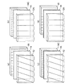
本実施形態およびその変形例による表示装置は、図14(a)、14(b)、14(c)、14(d)に示すように、4種類のパターンに分類される。これらの4種類のパターンは、
光学的開口部の開口の稜線方向と、線光源装置の線光源の稜線方向が平行か、傾いているかの状態によって分類される。
The display device according to the present embodiment and its modification is classified into four types of patterns as shown in FIGS. 14 (a), 14 (b), 14 (c), and 14 (d). These four types of patterns are
The ridge line direction of the opening of the optical opening and the ridge line direction of the line light source of the line light source device are classified according to whether they are parallel or inclined.
図14(a)においては、光学的開口部12の各開口が表示パネルの列方向に対して斜めに傾斜しており、線光源装置16の各線光源の稜線方向は上記列方向に延在している。図14(b)においては、光学的開口部の各開口が上記列方向に延在しており、線光源装置の各線光源の稜線方向は上記列方向に対して斜めに傾斜している。図14(c)においては、光学的開口部の各開口の稜線方向と、線光源装置の各線光源の稜線方向とは平行であり、その方向は上記列方向に延在している。図14(d)においては、光学的開口部の各開口の稜線方向と、線光源装置の各線光源の稜線方向とは平行であり、その方向は上記列方向に対して斜めに傾斜している。
In FIG. 14A, each opening of the
これらの4方式によって2次元画像表示モードと3次元画像Dモードの拡散状態が異なり、その組み合わせを図15に示す。図中の方式a〜dは図14(a)〜14(d)に対応し、Va〜Vdは各方式の拡散状態を示すヘーズ値であり、添え字2Dと3Dはそれぞれ2次元画像表示モードと3次元画像表示モードを示している。方式a〜cの拡散状態の組み合わせはほぼ同一であり、2次元画像表示モードの状態では実質的にむらが視認できなくなる値となる。一方、方式a〜cの3次元画像表示モードの拡散状態Va−3D、Vb−3D、Vc−3Dも同様に、拡散状態0〜実質的にむらが視認できなくなる値となる。3次元画像表示モードの場合、輝度むらが視認できないよう、光源の形状に工夫が施されている場合は、拡散状態が0のままで良い。方式cは2次元画像表示モードと3次元画像表示モードは共に輝度むらが最も視認されやすい構造で、両モードとも拡散状態を必要とする。方式dは、2次元画像表示モードの時は最大の拡散状態となり、3次元画像表示モードの時は実質的に輝度むらが視認できなくなる値であるが、その値Vd−3Dは方式a〜cの拡散状態Va−3D、Vb−3D、Vc−3Dよりは大きい。輝度むらの視認性は個人差があるファクターであり、ユーザーによって拡散状態を自由に変化させる機能を、例えば図4に示す拡散状態制御部26に備えていても良い。
The diffusion state of the two-dimensional image display mode and the three-dimensional image D mode differs depending on these four methods, and the combination is shown in FIG. In the figure, methods a to d correspond to FIGS. 14A to 14D, Va to Vd are haze values indicating the diffusion state of each method, and subscripts 2D and 3D are two-dimensional image display modes, respectively. And 3D image display mode. The combinations of the diffusion states of the methods a to c are almost the same, and the values are substantially invisible in the state of the two-dimensional image display mode. On the other hand, the diffusion state Va -3D of the three-dimensional image display mode method a to c, Vb -3D, Vc -3D likewise a
以上説明したように、第1実施形態およびその変形例によれば、2次元画像と3次元画像の切替えを行っても画質の低下及び光利用効率の低下を抑制することができる。 As described above, according to the first embodiment and the modifications thereof, it is possible to suppress a decrease in image quality and a decrease in light utilization efficiency even when switching between a two-dimensional image and a three-dimensional image.
(第2実施形態)
次に、第1実施形態の表示装置に用いられるバックライト装置について、より詳細に説明する。
(Second Embodiment)
Next, the backlight device used in the display device of the first embodiment will be described in more detail.
第2実施形態によるバックライト装置の線光源装置16を図16に示す。この第2実施形態に係る線光源装置16は、面光源40と、この面光源40上に設けられた透明基板42と、この透明基板42上に設けられ、所定の幅を有しライン状にパターニングされた例えばITO(Indium Tin Oxide)から形成された複数の透明電極44と、透明基板42および透明電極44の上方に設けられた例えばITOから形成される透明な対向電極48と、透明基板42および透明電極44と対向電極48との間に挟持された分散型液晶層46と、対向電極48上に設けられた透明基板50と、を備えている。透明電極44と対向電極48との間に電圧を印加すると、透明電極44上の分散型液晶層46のみに拡散状態が除去されて透明状態になる。このため、面光源40から発生された光は、透明基板42、電圧が印加された透明電極44、透明状態の液晶層46、対向電極48、および透明基板50を透過した光が線光源となる。
The line
(第1変形例)
第2実施形態の第1変形例による線光源装置16を図17に示す。この第1変形例の線光源装置16は、図16に示す第2実施形態の線光源装置において、一つの面光源40を複数の面光源となるエッジ光源41に置き換えるとともに、透明基板42を透明基板42Aに置き換えた構成となっている。透明基板42Aは導光板の機能を有し、透明基板42Aの一つの側面に複数のエッジ光源41が設けられている。そして、エッジ光源41が設けられた側面から、対向する側面に向かって断面積が小さくなるように、楔型の形状を透明基板42Aは有している。
(First modification)
A line
また、第1変形例においては、エッジ光源41から出射される光線の光軸が各透明電極44の延在する方向と略直交するように配置される構成となっている。このような構成にすることにより、画像の書き換え周期に同期させて、エッジ光源41の順次点滅時間を位置ごとに異ならせるスキャニングが行え、線光源装置16の薄型化が行える。ただし、エッジ光源41の配置は、それぞれのエッジ光源から出射される光の光軸が透明電極44の延在する方向と略平行になるように設置しても、透明電極44は線光源として機能することができる。このように、透明電極44で線光源を形成する場合、線光源の形状が線状や市松模様などのパターンが形成し易い。また透明電極44を複数組に分け、それぞれの組に印加する電圧を異ならせて拡散状態を変化させることにより、線光源自体の輝度分布を制御することが可能となる。
In the first modification, the optical axis of the light beam emitted from the
(第2変形例)
第2実施形態の第2変形例による線光源装置16を図18に示す。この第2変形例の線光源装置16は、図16に示す第2実施形態の線光源装置において、一つの面光源40を複数の面光源となるエッジ光源41に置き換えるとともに、パターニングされた複数の透明電極44を、透明基板42上に設けられた一枚の透明電極43と、この透明電極43上に設けられ線光源の形状にパターニングされた散乱部45とに置き換えた構成となっている。
(Second modification)
A line
複数のエッジ光源41は、透明電極43上の端部に設けられ、それぞれから出射する光線の光軸が、散乱部45の線光源形状のそれぞれの部分が延在する方向に略直交するように配置される。透明電極43は例えばITOから形成される。散乱部45は、透明電極43と、対向電極48との間に電圧を印加することにより、分散型液晶層46の拡散状態が除去される。この状態で、エッジ光源41から出射された光は、透明電極43上に設けられた線光源の形状にパターニングされた散乱部45によって散乱され、分散型液晶層46、透明な対向電極48、および透明基板50を通って外部に出射される。したがって、この第2変形例の線光源装置16から外部に出射される光は、パターニングされた散乱部45の形状、すなわち線光源形状となる。このように、散乱部45は、線光源の機能を果たすことになる。
The plurality of edge
なお、散乱部45としては、例えば、二酸化チタンや硫化バリウム、或いはそれらの混合物などの反射率の高い白インク、または銀蒸着などを印刷によって形成したドット散乱素子、またはエッチングによってドット状の溝を形成し、散乱処理を施した散乱素子を用いることができる。
As the scattering
また、この第2変形例も、エッジ光源41から出射される光の光軸が、線光源の機能を果たす散乱部45のそれぞれの部分が延在する方向に略直交するように配置されているので、図17に示す第1変形例で説明したと同様に、画像の書き換え周期に同期させて、エッジ光源41の順次点滅時間を位置ごとに異ならせるスキャニングが行え、線光源装置16の薄型化が行える。
This second modification is also arranged so that the optical axis of the light emitted from the
なお、エッジ光源41の配置はそれぞれのエッジ光源から出射される光の光軸が散乱部45のそれぞれの延在する方向と略平行になるように設置しても、散乱部45は線光源としての機能を果たすことができる。
Even if the arrangement of the
(第3変形例)
第2実施形態の第3変形例による線光源装置16を図19に示す。この第3変形例の線光源装置16は、図18に示す線光源装置において、複数の面光源となるエッジ光源41の配置を、それぞれのエッジ光源から出射される光の光軸が散乱部45のそれぞれの延在する方向と略平行になるようにするとともに、透明基板50上に、複数のプリズムを有するプリズムアレイ52を設けた構成となっている。プリズムアレイ52のそれぞれのプリズムは、エッジ光源41から出射される光の光軸方向に延在する稜線を有し、上記光軸と平行な方向に配列される。このような構成とすることにより、光線分布の広がりを抑制することができる。
(Third Modification)
A line
(第4変形例)
第2実施形態の第4変形例による線光源装置16を図20に示す。この第4変形例の線光源装置16は、図18に示す第2変形例の線光源装置において、透明基板50上に拡散板53を設けた構成となっている。この拡散板53は、線光源の機能を果たす散乱部45のそれぞれの部分が延在する方向に、ドットパターンで透明基板50上に取り出された光を拡散する機能を有している。この拡散板53を設けることにより、ドットパターンで透明基板50上に取り出された光を、さらに精度よく線状の光線にすることができる。
(Fourth modification)
A line
以上説明したように、第2実施形態およびその変形例によれば、2次元画像と3次元画像の切替えを行っても画質の低下及び光利用効率の低下を抑制することができる。 As described above, according to the second embodiment and the modification thereof, it is possible to suppress a decrease in image quality and a decrease in light utilization efficiency even when switching between a two-dimensional image and a three-dimensional image.
本発明のいくつかの実施形態を説明したが、これらの実施形態は、例として提示したものであり、発明の範囲を限定することは意図していない。これらの実施形態は、その他の様々な形態で実施されることが可能であり、発明の要旨を逸脱しない範囲で、種々の省略、置き換え、変更を行うことができる。これらの実施形態やその変形は、発明の範囲や要旨に含まれると同様に、特許請求の範囲に記載された発明とその均等の範囲に含まれるものである。 Although several embodiments of the present invention have been described, these embodiments are presented by way of example and are not intended to limit the scope of the invention. These embodiments can be implemented in various other forms, and various omissions, replacements, and changes can be made without departing from the scope of the invention. These embodiments and modifications thereof are included in the invention described in the claims and equivalents thereof as well as included in the scope and gist of the invention.
2 表示パネル
10 バックライト装置
10A バックライト装置
10B バックライト装置
10C バックライト装置
12 光学的開口部
12A 光学的開口部
14 拡散状態切替え素子
16 線光源装置
20 制御部
22 同期制御部
24 表示画像制御部
26 拡散制御部
28 光源制御部
30 記憶部
40 面光源
41 エッジ光源
42 透明基板
43 透明電極
44 透明電極
45 散乱部
46 分散型液晶層
48 対向電極
50 透明基板
52 プリズムアレイ
53 拡散板
DESCRIPTION OF
Claims (10)
前記光学的開口のそれぞれに対応して設けられた線状の光を発生する少なくとも1個の線光源を有し、それぞれの線光源が互いに並列に配列された線光源装置と、
前記光学的開口のそれぞれに対応する領域において、前記線光源装置からの光の拡散状態を切り替えることが可能な拡散状態切替え素子と、
を備えたことを特徴とするバックライト装置。 An optical aperture having a plurality of optical apertures arranged in parallel to each other;
A linear light source device having at least one linear light source that generates linear light provided corresponding to each of the optical apertures, wherein the linear light sources are arranged in parallel with each other;
A diffusion state switching element capable of switching a diffusion state of light from the line light source device in a region corresponding to each of the optical apertures;
A backlight device comprising:
対向する透明な第1および第2基板と、
前記第1基板に対して前記第2基板と反対側に設けられた面光源と、
前記第1基板の前記第2基板が位置する側の面上に設けられ、それぞれが互いに並列に配置されたライン状の複数の透明電極と、
前記第2基板の前記第1基板が位置する側の面上に設けられ、複数の前記透明電極に対向する透明な対向電極と、
前記第1基板と前記第2基板との間に挟持された液晶層と、
を備えていることを特徴とする請求項1記載のバックライト装置。 The line light source device is:
Opposing transparent first and second substrates;
A surface light source provided on the opposite side to the second substrate with respect to the first substrate;
A plurality of line-shaped transparent electrodes provided on the surface of the first substrate on which the second substrate is located, each of which is arranged in parallel;
A transparent counter electrode provided on a surface of the second substrate on which the first substrate is located, and facing a plurality of the transparent electrodes;
A liquid crystal layer sandwiched between the first substrate and the second substrate;
The backlight device according to claim 1, further comprising:
対向する透明な第1および第2基板と、
前記第1基板の第1側面に設けられそれぞれが面光源となる複数のエッジ光源と、
前記第1基板の前記第2基板が位置する側の面上に設けられ、それぞれが互いに並列に配置されたライン状の複数の透明な電極と、
前記第2基板の前記第1基板が位置する側の面上に設けられ、複数の前記透明電極に対向する透明な対向電極と、
前記第1基板と前記第2基板との間に挟持された液晶層と、
を備え、
前記第1側面は、複数の前記電極のそれぞれが延在する方向に平行であり、
前記第1基板は、前記第1側面から、この第1側面に対向する第2側面に向かうにつれて断面積が減少する形状を有していることを特徴とする請求項1記載のバックライト装置。 The line light source device is:
Opposing transparent first and second substrates;
A plurality of edge light sources provided on the first side surface of the first substrate, each serving as a surface light source;
A plurality of line-shaped transparent electrodes provided on a surface of the first substrate on which the second substrate is located, each of which is arranged in parallel;
A transparent counter electrode provided on a surface of the second substrate on which the first substrate is located, and facing a plurality of the transparent electrodes;
A liquid crystal layer sandwiched between the first substrate and the second substrate;
With
The first side surface is parallel to a direction in which each of the plurality of electrodes extends,
The backlight device according to claim 1, wherein the first substrate has a shape in which a cross-sectional area decreases from the first side surface toward a second side surface facing the first side surface.
対向する透明な第1および第2基板と、
前記第1基板の前記第2基板が位置する側の面上に設けられた透明な第1電極と、
前記第2基板の前記第1基板が位置する側の面上に設けられ、前記第1電極に対向する透明な第2電極と、
前記第1基板と前記第2基板との間に挟持された液晶層と、
前記第1電極の前記第2電極が位置する側の面上の端部に設けられそれぞれが面光源となる複数のエッジ光源と、
前記第1電極の前記第2電極が位置する側の面上に、それぞれが互いに並列にかつ線光源状に設けられて前記エッジ光源からの光を散乱する複数の散乱部と、
を備えていることを特徴とする請求項1記載のバックライト装置。 The line light source device is:
Opposing transparent first and second substrates;
A transparent first electrode provided on a surface of the first substrate on which the second substrate is located;
A transparent second electrode provided on the surface of the second substrate on which the first substrate is located, and facing the first electrode;
A liquid crystal layer sandwiched between the first substrate and the second substrate;
A plurality of edge light sources each provided at an end of a surface of the first electrode on the side where the second electrode is located, each serving as a surface light source;
A plurality of scattering portions that are provided in parallel with each other on the surface of the first electrode on which the second electrode is located to scatter light from the edge light source; and
The backlight device according to claim 1, further comprising:
画像を表示する表示パネルと、
前記バックライト装置の線光源装置の点灯モードに同期して、前記バックライト装置の拡散状態切替え素子の前記拡散状態の切り替えを制御する拡散制御部と、
を備えていることを特徴とする表示装置。 The backlight device according to any one of claims 1 to 6,
A display panel for displaying images,
A diffusion control unit that controls switching of the diffusion state of the diffusion state switching element of the backlight device in synchronization with the lighting mode of the linear light source device of the backlight device;
A display device comprising:
それぞれの線光源の点滅を順次切り替える光源制御部と、
線光源の点灯タイミングと前記表示パネルの要素画像の切り替えを同期さる同期制御部と、
を更に備えることを特徴とする請求項7記載の表示装置。 A plurality of the line light sources are provided corresponding to the respective optical apertures,
A light source controller that sequentially switches blinking of each line light source,
A synchronization control unit for synchronizing the lighting timing of the line light source and the switching of the element image of the display panel;
The display device according to claim 7, further comprising:
前記拡散状態切替え素子の拡散状態は前記拡散状態切替え素子に印加される電圧値により制御され、かつ2次元画像表示モードでは拡散状態、3次元画像表示モードでは輝度むらが実質的に視認されない拡散状態になることを特徴とする請求項7または8記載の表示装置。 The extending direction of each opening of the optical opening is inclined with respect to the extending direction of the line light source,
The diffusion state of the diffusion state switching element is controlled by a voltage value applied to the diffusion state switching element, and is a diffusion state in the two-dimensional image display mode and a diffusion state in which luminance unevenness is not substantially visible in the three-dimensional image display mode. The display device according to claim 7 or 8, wherein
前記拡散状態切替え素子の拡散状態は前記拡散状態切替え素子に印加される電圧値により制御され、2次元画像表示モードでは実質的に輝度むらが視認されないかまたはヘーズ値が最大の拡散状態であり、3次元画像表示モードでは輝度むらが実質的に視認されない拡散状態になることを特徴とする請求項7または8記載の表示装置。 The extending direction of each opening of the optical opening is parallel to the extending direction of the line light source,
The diffusion state of the diffusion state switching element is controlled by a voltage value applied to the diffusion state switching element, and in the two-dimensional image display mode, the luminance unevenness is substantially not visually recognized or the haze value is the maximum diffusion state, The display device according to claim 7 or 8, wherein in the three-dimensional image display mode, the luminance unevenness is substantially not visually recognized.
Priority Applications (3)
| Application Number | Priority Date | Filing Date | Title |
|---|---|---|---|
| JP2010252008A JP2012104375A (en) | 2010-11-10 | 2010-11-10 | Display device and backlight device |
| US13/049,958 US20120113358A1 (en) | 2010-11-10 | 2011-03-17 | Display apparatus and back light apparatus |
| CN2011102355885A CN102466178A (en) | 2010-11-10 | 2011-08-17 | Display apparatus and back light apparatus |
Applications Claiming Priority (1)
| Application Number | Priority Date | Filing Date | Title |
|---|---|---|---|
| JP2010252008A JP2012104375A (en) | 2010-11-10 | 2010-11-10 | Display device and backlight device |
Publications (1)
| Publication Number | Publication Date |
|---|---|
| JP2012104375A true JP2012104375A (en) | 2012-05-31 |
Family
ID=46019336
Family Applications (1)
| Application Number | Title | Priority Date | Filing Date |
|---|---|---|---|
| JP2010252008A Pending JP2012104375A (en) | 2010-11-10 | 2010-11-10 | Display device and backlight device |
Country Status (3)
| Country | Link |
|---|---|
| US (1) | US20120113358A1 (en) |
| JP (1) | JP2012104375A (en) |
| CN (1) | CN102466178A (en) |
Cited By (1)
| Publication number | Priority date | Publication date | Assignee | Title |
|---|---|---|---|---|
| KR20170122687A (en) * | 2016-04-27 | 2017-11-06 | 한국광기술원 | Non optical plate multiview 2d/3d conversion parallax lighting system |
Families Citing this family (6)
| Publication number | Priority date | Publication date | Assignee | Title |
|---|---|---|---|---|
| JP2011175102A (en) * | 2010-02-24 | 2011-09-08 | Sony Corp | Optical sheet stack body, illuminating device and display device |
| JP6098064B2 (en) * | 2012-08-08 | 2017-03-22 | ソニー株式会社 | Display device and lighting device |
| KR101957837B1 (en) * | 2012-11-26 | 2019-03-13 | 엘지디스플레이 주식회사 | Display Device Including Line Light Source And Method Of Driving The Same |
| CN103018952B (en) * | 2012-12-21 | 2016-01-06 | 京东方科技集团股份有限公司 | Display base plate and comprise the display device of this display base plate |
| CN106530990A (en) * | 2016-12-27 | 2017-03-22 | 京东方科技集团股份有限公司 | Display device and display system |
| KR20210066797A (en) * | 2018-08-29 | 2021-06-07 | 피씨엠에스 홀딩스, 인크. | Optical method and system for light field display based on mosaic periodic layer |
Citations (3)
| Publication number | Priority date | Publication date | Assignee | Title |
|---|---|---|---|---|
| JPH05284542A (en) * | 1992-04-03 | 1993-10-29 | Nippon Telegr & Teleph Corp <Ntt> | Three-dimensional picture/two-dimensional picture coexistence type display device |
| JPH11285030A (en) * | 1998-03-26 | 1999-10-15 | Mr System Kenkyusho:Kk | Stereoscopic image display method and stereoscopic image display device |
| JP2010164852A (en) * | 2009-01-16 | 2010-07-29 | Toshiba Corp | Stereoscopic image display device and stereoscopic image display method |
Family Cites Families (3)
| Publication number | Priority date | Publication date | Assignee | Title |
|---|---|---|---|---|
| GB0328005D0 (en) * | 2003-12-03 | 2004-01-07 | Koninkl Philips Electronics Nv | 2D/3D Displays |
| CN1950744A (en) * | 2004-03-26 | 2007-04-18 | 独立行政法人科学技术振兴机构 | Three-dimensional display |
| JP2010091895A (en) * | 2008-10-10 | 2010-04-22 | Toppoly Optoelectronics Corp | Active matrix display device |
-
2010
- 2010-11-10 JP JP2010252008A patent/JP2012104375A/en active Pending
-
2011
- 2011-03-17 US US13/049,958 patent/US20120113358A1/en not_active Abandoned
- 2011-08-17 CN CN2011102355885A patent/CN102466178A/en active Pending
Patent Citations (3)
| Publication number | Priority date | Publication date | Assignee | Title |
|---|---|---|---|---|
| JPH05284542A (en) * | 1992-04-03 | 1993-10-29 | Nippon Telegr & Teleph Corp <Ntt> | Three-dimensional picture/two-dimensional picture coexistence type display device |
| JPH11285030A (en) * | 1998-03-26 | 1999-10-15 | Mr System Kenkyusho:Kk | Stereoscopic image display method and stereoscopic image display device |
| JP2010164852A (en) * | 2009-01-16 | 2010-07-29 | Toshiba Corp | Stereoscopic image display device and stereoscopic image display method |
Cited By (2)
| Publication number | Priority date | Publication date | Assignee | Title |
|---|---|---|---|---|
| KR20170122687A (en) * | 2016-04-27 | 2017-11-06 | 한국광기술원 | Non optical plate multiview 2d/3d conversion parallax lighting system |
| KR101967751B1 (en) * | 2016-04-27 | 2019-04-10 | 한국광기술원 | Non optical plate multiview 2d/3d conversion parallax lighting system |
Also Published As
| Publication number | Publication date |
|---|---|
| CN102466178A (en) | 2012-05-23 |
| US20120113358A1 (en) | 2012-05-10 |
Similar Documents
| Publication | Publication Date | Title |
|---|---|---|
| US7954967B2 (en) | Directional backlight, display apparatus, and stereoscopic display apparatus | |
| JP5698251B2 (en) | Autostereoscopic display device | |
| JP5674757B2 (en) | How to drive a color sequential display | |
| JP4840962B2 (en) | 3D display that can be displayed vertically or horizontally | |
| JP4492851B2 (en) | Parallax barrier and multiple display | |
| KR102662883B1 (en) | Glasses-free stereoscopic display device and display method | |
| JP5899389B1 (en) | Autostereoscopic display device | |
| WO2017092453A1 (en) | 3d display apparatus and drive method therefor | |
| JP5662290B2 (en) | Display device | |
| WO2017092708A1 (en) | 3d imaging device and a driving method thereof | |
| WO2017118058A1 (en) | Three-dimensional display device and method for driving same | |
| JP2012104375A (en) | Display device and backlight device | |
| US20170127050A1 (en) | Image data redundancy for high quality 3d | |
| JP2016531310A (en) | Autostereoscopic display device | |
| JP2019502171A (en) | Display device and display control method | |
| WO2017092397A1 (en) | Three-dimensional display device and driving method therefor | |
| TW201326905A (en) | Display device | |
| JP4865069B1 (en) | 3D image display device and display method | |
| US10462453B2 (en) | Display device and display control method | |
| KR101759540B1 (en) | 3-dimensional displaying apparatus and driving method thereof | |
| EP2905959A1 (en) | Autostereoscopic display device |
Legal Events
| Date | Code | Title | Description |
|---|---|---|---|
| A977 | Report on retrieval |
Free format text: JAPANESE INTERMEDIATE CODE: A971007 Effective date: 20121025 |
|
| A131 | Notification of reasons for refusal |
Free format text: JAPANESE INTERMEDIATE CODE: A131 Effective date: 20121102 |
|
| A02 | Decision of refusal |
Free format text: JAPANESE INTERMEDIATE CODE: A02 Effective date: 20130305 |