JP2012103097A - Reagent kit and autoanalyzer equipped with the same - Google Patents
Reagent kit and autoanalyzer equipped with the same Download PDFInfo
- Publication number
- JP2012103097A JP2012103097A JP2010251632A JP2010251632A JP2012103097A JP 2012103097 A JP2012103097 A JP 2012103097A JP 2010251632 A JP2010251632 A JP 2010251632A JP 2010251632 A JP2010251632 A JP 2010251632A JP 2012103097 A JP2012103097 A JP 2012103097A
- Authority
- JP
- Japan
- Prior art keywords
- measurement container
- measurement
- reagent
- container
- sample
- Prior art date
- Legal status (The legal status is an assumption and is not a legal conclusion. Google has not performed a legal analysis and makes no representation as to the accuracy of the status listed.)
- Pending
Links
Images


Landscapes
- Automatic Analysis And Handling Materials Therefor (AREA)
Abstract
Description
本発明は、例えば血液や血清といった試料(検体)中に含まれる成分を特異的に分析するための反応試薬を含む試薬キット、および前記キットを備えた自動分析装置に関する。 The present invention relates to a reagent kit including a reaction reagent for specifically analyzing a component contained in a sample (specimen) such as blood or serum, and an automatic analyzer including the kit.
近年、臨床検査に用いる分析装置は、搭載する各種アクチュエータ、センサおよびソフトウェアに関する技術の進歩、自動化の進展により、臨床検査に関わる人的コストの低減、測定者の負担の軽減に貢献してきた。しかしながら、自動化が進展してもなお人手で行なう作業は残されている。装置の処理速度が高くなればなるほど、検体や試薬の取り違いや検体の前処理等の人為的操作ミスが検査結果に及ぼす影響は拡大し、測定者への心理的圧迫感は増大する。 2. Description of the Related Art In recent years, analyzers used in clinical tests have contributed to the reduction of human costs related to clinical tests and the burden on measurers by the advancement of technology and automation related to various actuators, sensors and software installed. However, even if automation progresses, there is still work to be done manually. The higher the processing speed of the apparatus, the greater the influence of human operation errors such as sample and reagent misplacement and sample pretreatment on test results, and the psychological pressure on the measurer increases.
自動分析装置で使用する検査試薬(試薬キット)の供給形態として、
(a)そのままで使用できるストレート液の形態、
(b)水で希釈して使用する濃縮液の形態、
(c)解凍して使用する凍結形態、
(d)再溶解液を加えて使用する凍結乾燥形態、
が例示できる。このうち(a)の形態は、そのまま使用できる点で測定者への負担は軽いものの、体積と重さの点で運送面においては不利である。一方、(b)から(d)の形態は、検査試薬として使用するにはそれぞれ、(b)の形態では希釈操作、(c)の形態では解凍操作、(d)の形態では再溶解操作を必要とし、前記操作を測定者の手作業で行なう場合は測定者への負担が発生する。
As a supply form of the test reagent (reagent kit) used in the automatic analyzer,
(A) Straight liquid form that can be used as is,
(B) The form of the concentrate used after diluting with water,
(C) frozen form to be used after thawing;
(D) a freeze-dried form to be used by adding a redissolved solution,
Can be illustrated. Among these, the form (a) can be used as it is and the burden on the measurer is light, but it is disadvantageous in terms of transportation in terms of volume and weight. On the other hand, in the forms (b) to (d), in order to use as a test reagent, a dilution operation is performed in the form (b), a thawing operation is performed in the form (c), and a re-dissolution operation is performed in the form (d). If it is necessary and the above operation is performed manually by the measurer, a burden on the measurer is generated.
一般に、自動分析装置に試薬を載置する場合、発生し得る人為的誤操作には、調液・前処理における誤操作と、試薬の取り違い(または置き違い)が考えられる。これらの人為的誤操作は、装置で自動化することによりその大部分を克服することが可能である。調液・前処理における誤操作のうち、(b)の形態における希釈操作や(d)の形態における再溶解操作での誤操作は自動分析装置に備えた分注手段によって一部解決することができる。また、(c)の形態における解凍操作は自動分析装置に備えた温調手段を利用することで解決することができる。試薬の取り違いまたは置き違いは、試薬容器に識別コード(ドットコードやバーコード等)を付し、前記識別コードを読取可能な読取手段を自動分析装置に備えることで一部解決することができる。一般に前記読取手段は、識別コードを読み取るとともに変位センサやパルスモータ等により試薬容器の座標を記憶することができるからである。 In general, when a reagent is placed on an automatic analyzer, an erroneous operation that may occur may be an erroneous operation in preparation or pretreatment and a reagent misplacement (or misplacement). Most of these artificial mistakes can be overcome by automating the apparatus. Among the misoperations in the preparation and pretreatment, the misoperation in the dilution operation in the form (b) and the re-dissolution operation in the form (d) can be partially solved by the dispensing means provided in the automatic analyzer. Further, the thawing operation in the form (c) can be solved by using the temperature control means provided in the automatic analyzer. A reagent misplacement or misplacement can be partially solved by attaching an identification code (dot code, bar code, etc.) to the reagent container and providing the automatic analyzer with a reading means capable of reading the identification code. . This is because the reading means generally reads the identification code and can store the coordinates of the reagent container by a displacement sensor, a pulse motor or the like.
不均一系の免疫測定を行なう自動分析装置の場合、通常、試料・試薬類(試薬キット)として以下に示す構成品の全てまたはその一部を使用する。
(1)固相担体に結合した抗体等の特異的結合剤と、標識物質を結合した他の特異的結合剤とを含む反応試薬
(2)測定試料(検体)
(3)既知量の目的成分を含む検量線作成用の標準品(キャリブレータまたは液体ならば標準液ともいう)
(4)精度管理試料(コントロールともいう)
(5)測定範囲を超える濃度で存在する目的成分または過剰な妨害成分を含む検体を希釈するために検査項目に特有または共通に追加する検体希釈液
(6)測定前に検体中の目的成分を検出可能な形態に変換する前処理試薬
(7)所定量を検体に追加することで検体の液性・粘性を均一にし測定結果を安定させるための、検査項目に共通の希釈水または緩衝液
(8)検査項目に共通の検出反応で使用する酵素基質または増感剤
(9)B/F(Bound/Free)分離(洗浄)で使用する洗浄水
このうち、検査項目に共通の試薬類((7)から(9))は、試薬キットの一部というよりは、分析装置の消耗品とみなすこともできる。これら共通の試薬類は、複数テスト分をまかなう量を用意することができ、それぞれ特徴的な容器に入れるようにすれば、測定者の人為的誤操作はあまり問題とならない。
In the case of an automatic analyzer that performs heterogeneous immunoassay, all or part of the following components are usually used as samples and reagents (reagent kits).
(1) a reaction reagent containing a specific binding agent such as an antibody bound to a solid phase carrier and another specific binding agent bound to a labeling substance (2) a measurement sample (specimen)
(3) A standard product for preparing a calibration curve containing a known amount of the target component (also called a standard solution if it is a calibrator or a liquid)
(4) Quality control sample (also called control)
(5) Specimen diluent added in common or common to the test item to dilute the sample containing the target component or excessive interfering component present at a concentration exceeding the measurement range (6) The target component in the sample before measurement Pre-treatment reagent (7) to be converted into a detectable form (7) Diluted water or buffer solution common to test items (in order to stabilize the measurement result by adding a predetermined amount to the sample to make the sample liquid and viscosity uniform) 8) Enzyme substrate or sensitizer used in detection reactions common to test items (9) Washing water used for B / F (Bound / Free) separation (washing) Of these, reagents common to test items (( 7) to (9)) can be regarded as consumables for the analyzer rather than a part of the reagent kit. These common reagents can be prepared in quantities sufficient for a plurality of tests, and if they are put in their respective characteristic containers, the operator's human error will not be a problem.
前記自動分析装置による測定で中心的な役割を担う反応試薬(1)については、装置に載置する場合の人為的誤操作の発生を考慮し、従来より種々の工夫がなされている。たとえば、1回分の測定に使用する試薬を個々の試薬容器に収容し、碁盤目状の保持穴を有するトレイに前記試薬容器を載置した形態で供給しているものがある(特許文献1参照)。一つのトレイに同種の試薬容器のみ収容されている場合、前記トレイの縁には収容する試薬容器の内容物を表示する識別コード(バーコード)が付されている。測定者は当該トレイを自動分析装置の所定の場所に収納する。自動分析装置に備えた読取手段は、試薬容器の有無を識別するセンサを兼ねており、試薬容器の配置情報を認識することができる。自動分析装置に備えた搬送手段は、前記認識した試薬容器の配置情報と別途与えられた検査プログラムとに基づき必要な試薬を選択して把持後、次工程(例えば、検体分注の処理部)に搬送する。他の工夫として、試薬容器を載置したトレイごと収納手段に載置するのではなく、単一の搬送手段上に個々の試薬容器と測定容器とが混在した状態で載置する装置構成が開示されている(特許文献2参照)。前記構成では、測定者による試薬容器等の置き違いが介入する余地が、トレイごと供給手段に供給する場合と比較し大きくなる。このため、測定試料について測定すべき1以上の特定成分を対応づけた検査プログラム(ワークリスト)と、搬送経路に沿って設置した読取手段により読み取った試薬容器の内容物の情報と、を照合することで、測定者の人為的ミスを排除または検知するようにしている。反応試薬(1)を、複数回測定分の反応試薬(たとえば標識試薬)が入った容器で供給する場合は通常、測定者は前記容器を自動分析装置の所定の位置に載置する。前記容器には識別コードが付されており、装置に前記容器の内容物を認識させることができる。自動分析装置は、測定プログラムに従い所定のタイミングで、前記容器内の試薬の一部を反応容器に自動分注することができる。 The reaction reagent (1), which plays a central role in the measurement by the automatic analyzer, has been variously devised conventionally in consideration of the occurrence of human error when placed on the apparatus. For example, a reagent used for one measurement is stored in each reagent container and supplied in a form in which the reagent container is placed on a tray having a grid-like holding hole (see Patent Document 1). ). When only one reagent container of the same type is stored in one tray, an identification code (bar code) indicating the contents of the stored reagent container is attached to the edge of the tray. The measurer stores the tray in a predetermined place of the automatic analyzer. The reading means provided in the automatic analyzer also serves as a sensor for identifying the presence or absence of the reagent container, and can recognize the arrangement information of the reagent container. The transport means provided in the automatic analyzer selects and grasps a necessary reagent based on the recognized reagent container arrangement information and a separately provided test program, and then performs the next process (for example, a sample dispensing processing unit). Transport to. As another contrivance, an apparatus configuration is disclosed in which individual reagent containers and measurement containers are placed in a mixed state on a single transport means, rather than being placed in the storage means together with the tray on which the reagent containers are placed. (See Patent Document 2). In the above-described configuration, the room for the intervention of the misplacement of the reagent container or the like by the measurer is larger than the case where the tray is supplied to the supply unit. For this reason, the inspection program (work list) in which one or more specific components to be measured for the measurement sample are associated with the information on the contents of the reagent container read by the reading means installed along the transport path is collated. Therefore, the human error of the measurer is eliminated or detected. When the reaction reagent (1) is supplied in a container containing a reaction reagent (for example, a labeling reagent) for a plurality of measurements, the measurer usually places the container at a predetermined position of the automatic analyzer. The container is provided with an identification code so that the apparatus can recognize the contents of the container. The automatic analyzer can automatically dispense a part of the reagent in the container into the reaction container at a predetermined timing according to the measurement program.
測定試料(2)については、検体を自動搬送する手段を利用しない施設では、測定者が介在して、採血管または自動分析装置専用の測定容器に収容した検体を、装置上の所定の場所に載置する作業があり得る。載置する採血管や測定容器には通常、識別コードが付されており、識別コードに付された検体の場所と情報を、装置に備えた読取手段で自動的に読み取ることができる。このため、測定者は検査依頼の順番と検体の並べ方との対応に注意を払う必要がない。一方、識別コードが付されていない採血管や測定容器の場合、自動分析装置に検体ID、検査項目、載置位置を含む検査依頼情報をあらかじめ入力後、入力した載置位置に検体容器を載置しなければならない。そのため、載置時に置き違い(載置ミス)が生じるおそれがある。 With respect to the measurement sample (2), in a facility that does not use means for automatically transporting the specimen, the specimen is placed in a predetermined place on the apparatus with a measurer intervening in a measuring tube dedicated to a blood collection tube or an automatic analyzer. There may be work to place. Usually, an identification code is attached to the blood collection tube or measurement container to be placed, and the location and information of the sample attached to the identification code can be automatically read by a reading means provided in the apparatus. For this reason, the measurer does not need to pay attention to the correspondence between the order of examination requests and the arrangement of specimens. On the other hand, in the case of a blood collection tube or a measurement container without an identification code, after the test request information including the sample ID, the test item, and the mounting position is input in the automatic analyzer in advance, the sample container is mounted at the input mounting position. Must be placed. For this reason, there is a risk of misplacement (placement error) during placement.
標準品(3)については、目的成分の有無にかかわらずすべてがそのまま使用できるストレート液で供給される場合、すべてが凍結乾燥形態で供給される場合、目的成分を含まないものはストレート液で目的成分を含むものは凍結乾燥形態で供給される場合等、種々の形態で供給される。標準品(3)が凍結乾燥形態で供給される場合は、測定者が所定量の再溶解液(通常は精製水)を加えて溶液とした後、装置専用の測定容器に移し替え、自動分析装置の指定する位置に載置する。この場合、調液時のミスおよび置き違いが発生し得る。 For the standard product (3), when everything is supplied in a straight solution that can be used as it is regardless of the presence or absence of the target component, when all are supplied in lyophilized form, those that do not contain the target component are used as a straight solution. Those containing ingredients are supplied in various forms, such as when supplied in lyophilized form. When the standard product (3) is supplied in lyophilized form, the measurer adds a predetermined amount of redissolved solution (usually purified water) to make a solution, then transfers the solution to a dedicated measuring container for automatic analysis. Place it at the position specified by the device. In this case, mistakes and misplacements during preparation can occur.
精度管理試料(4)については、凍結乾燥形態で供給される試料を使用する場合は、所定の再溶解液を分注して溶解後、測定試料(2)と同様に(たとえば自動分析装置専用の測定容器)に入れて装置上に載置する。載置した精度管理試料(4)は、精度管理試料(4)のラベルに付された識別コードをハンディスキャナで読み取ったり、精度管理試料の識別情報を入力したりすることで、装置に精度管理試料(4)の位置を認識させる。 As for the quality control sample (4), when using a sample supplied in lyophilized form, after dispensing and dissolving a predetermined re-dissolved solution, the same as for the measurement sample (2) (for example, dedicated to an automatic analyzer) And place on the apparatus. The placed quality control sample (4) can be managed by reading the identification code attached to the label of the quality control sample (4) with a handy scanner or inputting the identification information of the quality control sample. The position of the sample (4) is recognized.
検体希釈液(5)については、そのまま使用できるストレート液で供給される場合と濃縮液で供給される場合とがある。ストレート液で供給される場合は、前記液を収容した容器を所定位置にセットすればよい。濃縮液で供給される場合は、濃縮液から希釈調液する操作が必要であり、調液した測定複数回分の検体希釈液を専用の容器に移し替える。測定者は前記容器を装置の指定する位置に載置する。識別コードを付していれば、自動分析装置に備えた読取手段により、検体希釈液の位置および種類を認識することができる。いずれの場合も装置は、測定プログラムに従い、所定のタイミングで、検体希釈液を検体希釈用の容器に測定試料とともに自動分注する。検体希釈液についても、希釈調液時のミスおよび置き違い(載置ミス)が発生し得る。 The specimen dilution liquid (5) may be supplied as a straight liquid that can be used as it is or supplied as a concentrated liquid. When the liquid is supplied as a straight liquid, the container containing the liquid may be set at a predetermined position. When the concentrate is supplied, an operation of diluting and preparing from the concentrate is necessary, and the prepared specimen dilution liquid for a plurality of times of measurement is transferred to a dedicated container. The measurer places the container at a position designated by the apparatus. If the identification code is attached, the position and type of the sample diluent can be recognized by the reading means provided in the automatic analyzer. In either case, the apparatus automatically dispenses the sample diluent together with the measurement sample into the sample dilution container at a predetermined timing according to the measurement program. Also for the sample dilution liquid, errors and misplacements (placement errors) may occur during dilution preparation.
前処理試薬(6)については、凍結乾燥形態、溶液形態、またはそれらが混在した状態で供給される複数の試薬から構成される前処理試薬セットが例示できる。前処理の方法として、前記構成試薬同士を混合した後、検体に接触させたり、前記接触を所定時間行なった後、別の前処理試薬で処理したりする方法がある。試薬同士を混合する際は手作業が必要であり、装置に載置するのも人手で行なうこととなる。この場合、前処理操作のミスおよび置き違い(載置ミス)が発生し得る。 As for the pretreatment reagent (6), a pretreatment reagent set composed of a plurality of reagents supplied in a freeze-dried form, a solution form, or a mixture thereof can be exemplified. As a pretreatment method, there is a method in which the constituent reagents are mixed with each other and then contacted with a specimen, or the contact is performed for a predetermined time and then treated with another pretreatment reagent. When the reagents are mixed with each other, manual work is required, and the reagent is manually placed on the apparatus. In this case, mistakes in the preprocessing operation and misplacements (placement mistakes) may occur.
前述した試薬の調液操作や置き違いを極力回避し、かつ自動分析装置の自動化を進めるために、1回の測定に必要な試薬類のほぼすべてを複数のウェルに分けて収納した試薬カートリッジが開示されている(たとえば特許文献3および4参照)。前記カートリッジには、試薬を収容したウェル、検体希釈液を収容したウェル、洗浄液を収容したウェル、酵素基質を収容したウェル等が設けられている。
In order to avoid the reagent preparation and misplacement of the reagents as much as possible, and to advance automation of the automatic analyzer, there is a reagent cartridge that contains almost all of the reagents required for one measurement divided into multiple wells. (See, for example,
前述したように、自動分析装置で使用する測定試薬の供給形態には種々の形態があり、自動分析装置に試薬を載置する場合、発生し得る人為的誤操作には、調液・前処理における誤操作と、試薬の取り違い(または載置ミス)がある。前記人為的誤操作は、その大部分を装置の自動化で克服することが可能である。しかしながら、従来の試薬は、その供給形態や容器の形状がまちまちであるため、誤操作の余地が依然として残されている。このため、測定者への負担が大きく、緊張や疲労等により誤った検査結果を生むおそれが無視できない。 As described above, there are various forms of supply of the measurement reagent used in the automatic analyzer, and when a reagent is placed on the automatic analyzer, an artificial error that may occur is in preparation and pretreatment. There are misoperations and reagent misplacement (or mounting errors). Most of the human error can be overcome by automation of the apparatus. However, since the conventional reagent has various supply forms and container shapes, there is still room for erroneous operation. For this reason, the burden on the measurer is large, and the possibility of producing erroneous test results due to tension, fatigue, etc. cannot be ignored.
反応試薬(1)を収容する容器、標準品(3)を収容する容器、精度管理試料(4)を収容する容器、検体希釈液(5)を収容する容器、および前処理試薬(6)を収容する容器との間で容器の形状や外観が異なれば、測定者がそれらを識別したり操作するのには好ましい。しかしながら、供給者にとっては生産設備を多様化しなければならず、経済的に不都合である。さらに、種々の形状の容器を有した形態で、自動分析装置を用いた測定操作の自動化を進めると、搬送手段や収納手段を多様化する必要があるため、部品種類数の増加および装置の大型化につながる。 A container containing the reaction reagent (1), a container containing the standard product (3), a container containing the quality control sample (4), a container containing the sample diluent (5), and a pretreatment reagent (6) If the shape and appearance of the container are different from those of the containers to be stored, it is preferable for the measurer to identify and operate them. However, for the supplier, production facilities must be diversified, which is economically inconvenient. Furthermore, when automation of measurement operations using automatic analyzers with variously shaped containers is required, it is necessary to diversify the transport means and storage means, which increases the number of component types and the size of the apparatus. Leading to
1回の測定に必要な試薬をそろえた専用の多ウェル型カートリッジ(特許文献3および4参照)は、特定の目的成分を専用に測定する装置に対しては好ましいが、多様な測定試薬や測定方法への対応が必要な汎用の自動分析装置には必ずしも適していない(特許文献4参照)。
Dedicated multi-well cartridges (see
標準品(3)を用いる検量線の作成頻度および精度管理試料(4)の測定頻度は、自動分析装置を設置した検査室における精度管理スケジュールに従い決定される。また、試薬ロットの変更や測定条件の変更等に伴い検量線を更新する場合も多い。さらに検体の希釈が必要な検査項目や前処理が必要な検査項目は一部の項目に限定される。いずれにしても使用頻度の比較的低い標準品(3)、精度管理試料(4)、検体希釈液(5)、前処理試薬(6)を、反応試薬(1)の試薬カートリッジに組み込むのは好ましくない。たとえば、数回の希釈が必要な項目と希釈が不要な項目とで同じ形の試薬カートリッジを使う場合、希釈が不要な項目では希釈液用のウェルは使用しないためむだになる。また、試薬カートリッジが大型化するため、自動分析装置に備える搬送手段の設計の自由度が限定される。 The frequency of preparing a calibration curve using the standard product (3) and the frequency of measuring the quality control sample (4) are determined according to the quality control schedule in the laboratory where the automatic analyzer is installed. In many cases, the calibration curve is updated as the reagent lot is changed or the measurement conditions are changed. Furthermore, inspection items that require sample dilution and inspection items that require pretreatment are limited to some items. In any case, the standard product (3), the quality control sample (4), the sample diluent (5), and the pretreatment reagent (6), which are relatively infrequently used, are incorporated into the reagent cartridge of the reaction reagent (1). It is not preferable. For example, if the same type of reagent cartridge is used for an item that requires several dilutions and an item that does not require dilution, the dilution well is not used for the items that do not require dilution. Further, since the reagent cartridge is increased in size, the degree of freedom in designing the transport means provided in the automatic analyzer is limited.
そこで本発明は、自動分析装置で使用する測定試薬を取り扱うにあたり、測定者の負担を軽減し、また測定試薬の供給者の生産設備および自動分析装置の設計の合理化に適した試薬キットを提供することを目的とする。 Therefore, the present invention provides a reagent kit that reduces the burden on the measurer when handling the measurement reagent used in the automatic analyzer, and that is suitable for rationalizing the design of the production facility of the measurement reagent and the automatic analyzer. For the purpose.
前記目的を達成するためになされた本発明は、以下の発明を包含する:
第一の発明は、
(1)反応試薬を収容した測定容器と、
(2)標準品の構成成分を収容した測定容器、精度管理試料の構成成分を収容した測定容器、検体希釈液の構成成分を収容した測定容器、検体を前処理する前処理試薬を収容した測定容器、のうちの少なくとも一つ以上と、
を備えた試薬キットであって、
前記反応試薬を収容した測定容器、前記標準品の構成成分を収容した測定容器、前記精度管理試料の構成成分を収容した測定容器、前記検体希釈液の構成成分を収容した測定容器、および前記検体を前処理する前処理試薬を収容した測定容器の外部形状がいずれも同一である、前記キットである。
The present invention made to achieve the above object includes the following inventions:
The first invention is
(1) a measurement container containing a reaction reagent;
(2) Measurement container containing the standard component, measurement container containing the quality control sample component, measurement container containing the sample diluent component, measurement containing the pretreatment reagent for pretreatment of the sample At least one of the containers, and
A reagent kit comprising:
A measurement container containing the reaction reagent, a measurement container containing the components of the standard product, a measurement container containing the components of the quality control sample, a measurement container containing the components of the specimen diluent, and the sample In the kit, the external shapes of the measurement containers containing pretreatment reagents for pretreating are all the same.
第二の発明は、
(1)反応試薬を収容した測定容器を複数載置した測定容器収納トレイと、
(2)標準品の構成成分を収容した測定容器を複数載置した測定容器収納トレイ、精度管理試料の構成成分を収容した測定容器を複数載置した測定容器収納トレイ、検体希釈液の構成成分を収容した測定容器を複数載置した測定容器収納トレイ、検体を前処理する前処理試薬を収容した測定容器を複数載置した測定容器収納トレイ、のうちの少なくとも一つ以上と、
を備えた試薬キットであって、
前記反応試薬を収容した測定容器、前記標準品の構成成分を収容した測定容器、前記精度管理試料の構成成分を収容した測定容器、前記検体希釈液の構成成分を収容した測定容器および前記検体を前処理する前処理試薬を収容した測定容器の外部形状がいずれも同一であり、
前記反応試薬を収容した測定容器を複数載置するための測定容器収納トレイ、前記標準品の構成成分を収容した測定容器を複数載置するための測定容器収納トレイ、前記精度管理試料の構成成分を収容するための測定容器を複数載置するための測定容器収納トレイ、前記検体希釈液の構成成分を収容するための測定容器を複数載置するための測定容器収納トレイ、および前記検体を前処理する前処理試薬を収容するための測定容器を複数載置するための測定容器収納トレイの外部形状がいずれも同一である、前記キットである。
The second invention is
(1) a measurement container storage tray on which a plurality of measurement containers containing reaction reagents are placed;
(2) Measurement container storage tray on which a plurality of measurement containers containing standard constituent components are placed, measurement container storage tray on which a plurality of measurement containers containing constituent components of a quality control sample are placed, and constituent components of a sample diluent And at least one of a measurement container storage tray in which a plurality of measurement containers containing a pretreatment reagent for preprocessing a sample are placed,
A reagent kit comprising:
A measurement container containing the reaction reagent, a measurement container containing the components of the standard product, a measurement container containing the components of the quality control sample, a measurement container containing the components of the specimen diluent, and the sample The external shape of the measurement container containing the pretreatment reagent to be pretreated is the same,
Measurement container storage tray for mounting a plurality of measurement containers containing the reaction reagent, measurement container storage tray for mounting a plurality of measurement containers storing the components of the standard product, components of the quality control sample A measurement container storage tray for mounting a plurality of measurement containers for storing the sample, a measurement container storage tray for mounting a plurality of measurement containers for storing the components of the sample diluent, and the sample in front In the kit, the external shapes of the measurement container storage trays for mounting a plurality of measurement containers for storing pretreatment reagents to be processed are the same.
第三の発明は、前記測定容器の内容物がシールにより封入されており、前記シールの表面には前記内容物を識別するコードが付されている、第一または第二の発明に記載のキットである。 The third invention is the kit according to the first or second invention, wherein the contents of the measurement container are sealed with a seal, and a code for identifying the contents is attached to the surface of the seal. It is.
第四の発明は、前記測定容器が二つのウェルを連結した二連容器である、第一から第三の発明のいずれかに記載のキットである。 A fourth invention is the kit according to any one of the first to third inventions, wherein the measurement container is a double container in which two wells are connected.
第五の発明は、前記測定容器の内容物が凍結乾燥体である、第一から第四の発明のいずれかに記載のキットである。 A fifth invention is the kit according to any one of the first to fourth inventions, wherein the content of the measurement container is a lyophilized product.
第六の発明は、
測定容器を収納する収納手段と、
測定容器を搬送する搬送手段と、
測定容器に液体を吸引/吐出する分注手段と、
測定容器に収容した溶液を反応させる反応手段と、
測定容器に収容した溶液からの光を検出する検出手段と、
を備えた自動分析装置であって、
収納手段に収納する測定容器が、第一から第五の発明のいずれかに記載のキットに備えた測定容器である、前記自動分析装置である。
The sixth invention is
Storage means for storing the measurement container;
Conveying means for conveying the measurement container;
Dispensing means for sucking / discharging liquid into the measuring container;
A reaction means for reacting the solution contained in the measurement container;
Detection means for detecting light from the solution contained in the measurement container;
An automatic analyzer equipped with
In the automatic analyzer, the measurement container stored in the storage means is the measurement container provided in the kit according to any one of the first to fifth inventions.
第七の発明は、
第一から第五の発明のいずれかに記載のキットに備えた測定容器を収納する収納手段と、
収納手段に収納された測定容器を搬送する第一の搬送手段と、
測定容器に液体を吸引/吐出する分注手段と、
測定容器に収容した溶液を反応させる反応手段と、
測定容器を反応手段へ搬送する第二の搬送手段と、
測定容器に収容した溶液からの光を検出する検出手段と、
測定容器を検出手段へ搬送する第三の搬送手段と、
第一の搬送手段で搬送された測定容器を受け入れ、前記測定容器を、第二の搬送手段で反応手段へ搬送する位置、第三の搬送手段で検出手段へ搬送する位置、および分注手段で検体および/または分注水を吸引/吐出する位置へ移送可能な移送手段と、
を備えた自動分析装置である。
The seventh invention
Storage means for storing the measurement container provided in the kit according to any one of the first to fifth inventions;
First transport means for transporting the measurement container stored in the storage means;
Dispensing means for sucking / discharging liquid into the measuring container;
A reaction means for reacting the solution contained in the measurement container;
A second transport means for transporting the measurement container to the reaction means;
Detection means for detecting light from the solution contained in the measurement container;
A third transport means for transporting the measurement container to the detection means;
Accept the measurement container transported by the first transport means, position to transport the measurement container to the reaction means by the second transport means, position to transport to the detection means by the third transport means, and dispensing means Transport means capable of transporting the specimen and / or dispensed water to a position for aspirating / discharging;
It is an automatic analyzer equipped with.
第八の発明は、
移送手段が、
反応試薬を収容した測定容器を載置するための測定容器保持部と、
標準品の構成成分を収容した測定容器、精度管理試料の構成成分を収容した測定容器、検体希釈液の構成成分を収容した測定容器、検体を前処理する前処理試薬を収容した測定容器、のいずれかを載置するための測定容器保持部と、
を設けた手段である、第七の発明に記載の自動分析装置である。
The eighth invention is
The transport means is
A measurement container holding part for placing a measurement container containing a reaction reagent,
A measurement container containing a standard component, a measurement container containing a quality control sample component, a measurement container containing a sample diluent component, and a measurement container containing a pretreatment reagent for pretreating a sample A measurement container holding part for placing any one of them,
This is an automatic analyzer according to the seventh invention, which is means provided with the above.
以下、本発明を詳細に説明する。 Hereinafter, the present invention will be described in detail.
本発明における試薬とは、測定試料(検体)の測定に関与する化学品/生化学品を意味する。すなわち、標準品や精度管理試料を試薬として取り扱うことがある。また、本発明における測定容器とは、測定試料(検体)と試薬とを反応させて試料中の目的成分を測定するための測定容器または反応容器を意味するだけでなく、試薬を収容した試薬容器をも意味する。 The reagent in the present invention means a chemical / biochemical product involved in measurement of a measurement sample (specimen). In other words, standard products and quality control samples may be handled as reagents. In addition, the measurement container in the present invention means not only a measurement container or reaction container for reacting a measurement sample (sample) and a reagent to measure a target component in the sample, but also a reagent container containing a reagent. Also means.
本発明の試薬キットにより、測定者にとっては、自動分析装置に備えた収納手段に試薬を載置する際、反応試薬を収納手段に載置するのと同じ労力で、標準品、精度管理試料、試料希釈液、前処理試薬といった試薬類を載置することができる。一方、供給者にとっては、種々の形状の測定容器を製造する必要がないため、試薬の製造設備の合理化に資することができる。また、本発明の試薬キットを備えた自動分析装置(以下、単に本発明の自動分析装置とする)は、収納手段に収納できる測定容器数を最大化することができ、測定容器を搬送する搬送手段も共通化できるため、自動分析装置そのものの小型化・簡素化に資することができる。 With the reagent kit of the present invention, for the measurer, when placing the reagent in the storage means provided in the automatic analyzer, the standard product, the quality control sample, Reagents such as a sample diluent and a pretreatment reagent can be placed. On the other hand, since it is not necessary for the supplier to manufacture measurement containers of various shapes, it is possible to contribute to rationalization of reagent manufacturing facilities. Further, the automatic analyzer equipped with the reagent kit of the present invention (hereinafter simply referred to as the automatic analyzer of the present invention) can maximize the number of measurement containers that can be stored in the storage means, and transport the measurement containers. Since the means can also be made common, it can contribute to miniaturization and simplification of the automatic analyzer itself.
なお、本発明の試薬キットの測定容器に内容物を識別するためのコードを付し、前記コードの識別・読取が可能な読取手段を自動分析装置に設けると、自動分析装置はアッセイプログラムに従って、分析に必要な反応試薬、標準品、精度管理試料、検体希釈液、前処理試薬があるかを確認することができ、もしなければそれらの試料の載置を測定者に促すことができる。また、内容物を識別するためのコードを付すことで、収納手段の任意の場所に反応試薬、標準品、精度管理試料、検体希釈液、前処理試薬を載置することができる。そのため、測定者による試薬の載置ミスによる人為的誤操作を防ぐことができ、各測定項目における検体、標準品または精度管理試料の測定頻度の変化にも柔軟に対応することができる。 In addition, when a code for identifying the contents is attached to the measurement container of the reagent kit of the present invention and reading means capable of identifying and reading the code is provided in the automatic analyzer, the automatic analyzer is in accordance with the assay program. It is possible to confirm whether there are reaction reagents, standard products, quality control samples, specimen diluents, and pretreatment reagents necessary for analysis, and if not, it is possible to prompt the measurer to place these samples. Further, by attaching a code for identifying the contents, a reaction reagent, a standard product, a quality control sample, a specimen diluent, and a pretreatment reagent can be placed at any location in the storage means. For this reason, it is possible to prevent an erroneous manual operation due to a reagent placement error by the measurer, and to flexibly cope with a change in the measurement frequency of the specimen, the standard product, or the quality control sample in each measurement item.
本発明の試薬キットは、測定者による測定容器の取り扱いを容易にするために、試薬を収容した測定容器を複数載置した測定容器収納トレイの形で提供してもよく、特に、反応試薬を収容した測定容器を複数載置するための測定容器収納トレイ、標準品の構成成分を収容した測定容器を複数載置するための測定容器収納トレイ、精度管理試料の構成成分を収容するための測定容器を複数載置するための測定容器収納トレイ、検体希釈液の構成成分を収容するための測定容器を複数載置するための測定容器収納トレイ、および検体を前処理する前処理試薬を収容するための測定容器を複数載置するための測定容器収納トレイの外部形状をいずれも同一とすると、収納手段内に無駄なく測定容器を載置することができ、測定容器を複数載置した測定容器収納トレイを搬送する際も共通の搬送手段を用いて搬送できるため、自動分析装置の小型化・簡素化に資することができる点で、好ましい。 The reagent kit of the present invention may be provided in the form of a measurement container storage tray in which a plurality of measurement containers containing reagents are placed in order to facilitate the handling of the measurement container by a measurer. Measurement container storage tray for mounting a plurality of stored measurement containers, measurement container storage tray for mounting a plurality of measurement containers storing standard components, and measurement for storing components of a quality control sample Contains a measurement container storage tray for mounting a plurality of containers, a measurement container storage tray for mounting a plurality of measurement containers for storing the components of the sample diluent, and a pretreatment reagent for preprocessing the sample If the external shapes of the measurement container storage trays for mounting a plurality of measurement containers are the same, the measurement containers can be mounted in the storage means without waste. Since it conveyed using a common transport means is also in transporting the container housing tray, in that it can contribute to miniaturization and simplification of the automatic analyzer, preferably.
反応試薬を収容した測定容器と外部形状が同一な測定容器とは、内部形状は同一形状であってもよいし、同一形状でなくてもよいことを意味している。例えば、測定容器内部の底面の形状は、一般に、平面、球面、円錐面、放物面等種々の形状とすることができる。これら測定容器の内部形状は、容器に対する各操作(例えば、液体の注入、吸引、撹拌)への適否が多かれ少なかれ存在するため、目的に応じて適切な内部形状を採用すればよい。例えば、微量の液体を効果的に吸引するための測定容器には底面を円錐面とすると好ましいし、撹拌を目的とする測定容器には底面を球面とすると好ましいし、液体を分注する測定容器には底面を平面とし容器の深さを深くすると好ましい。つまり、本発明の試薬キットにおいて、反応試薬を収容した測定容器、標準品の構成成分を収容した測定容器、精度管理試料の構成成分を収容した測定容器、検体希釈液の構成成分を収容した測定容器、および検体を前処理する前処理試薬を収容した測定容器は、外部形状が同一であればよく、内部形状については各測定容器毎に最も好ましい形状を採用すればよい。一方で、反応試薬を収容した測定容器、標準品の構成成分を収容した測定容器、精度管理試料の構成成分を収容した測定容器、検体希釈液の構成成分を収容した測定容器、および検体を前処理する前処理試薬を収容した測定容器が、いずれも同一の外部形状および内部形状を有していてもよく、その場合は、測定容器製造用金型の共用化等、測定試薬生産設備の合理化を推進できるという利点がある。 The measurement container containing the reaction reagent and the measurement container having the same external shape means that the internal shape may or may not be the same shape. For example, the shape of the bottom surface inside the measurement container can generally be various shapes such as a flat surface, a spherical surface, a conical surface, and a paraboloid. Since the internal shape of these measurement containers has more or less suitability for each operation (for example, liquid injection, suction, and stirring), an appropriate internal shape may be adopted according to the purpose. For example, a measurement container for effectively sucking a small amount of liquid preferably has a conical bottom surface, and a measurement container for stirring purposes preferably has a spherical bottom surface. In this case, it is preferable that the bottom is a flat surface and the container is deep. That is, in the reagent kit of the present invention, a measurement container containing a reaction reagent, a measurement container containing a standard component, a measurement container containing a quality control sample component, and a measurement diluent containing a sample diluent component The container and the measurement container that contains the pretreatment reagent for pretreating the sample need only have the same external shape, and the internal shape may be the most preferable shape for each measurement container. On the other hand, a measurement container containing a reaction reagent, a measurement container containing a standard component, a measurement container containing a quality control sample component, a measurement container containing a sample diluent component, and a sample Measurement containers containing pretreatment reagents to be processed may all have the same external shape and internal shape. In that case, rationalization of measurement reagent production facilities, such as sharing of molds for manufacturing measurement containers There is an advantage that can be promoted.
本発明の試薬キットにおける測定容器の外部形状は、例えばチューブ、カップ、キュベットといった個別独立した凹状のウェル(開口部を一つ有したもの)、前記ウェルを2個以上連結したものが例示できる。測定容器の材質は特に限定されないものの、同一形状のものを大量に製造する点において樹脂製が好ましく、例えば、オレフィン系樹脂、スチレン系樹脂、ビニル系樹脂、カーボネート系樹脂、ポリエステル系樹脂、ポリアミド系樹脂といった熱可塑性樹脂を例示することができる。反応試薬、標準品、精度管理試料、検体希釈液または前処理試薬を収容した測定容器は、その上端開口部を、例えばヒートシール用アルミ箔やポリマーフィルムで密封すればよい。なお、前記シール表面に、内容物を識別するためのコード(バーコード、2次元コード等)をレーザマーカ等により印刷すると、自動分析装置に備えた前記コードを読み取る手段により、測定試薬の載置ミス等を防止できる点で好ましい。 Examples of the external shape of the measurement container in the reagent kit of the present invention include individual and independent concave wells (having one opening) such as tubes, cups, and cuvettes, and those in which two or more wells are connected. Although the material of the measurement container is not particularly limited, it is preferably made of a resin in terms of manufacturing a large number of the same shape. For example, an olefin resin, a styrene resin, a vinyl resin, a carbonate resin, a polyester resin, a polyamide resin A thermoplastic resin such as a resin can be exemplified. The measurement container containing the reaction reagent, standard product, quality control sample, specimen diluent or pretreatment reagent may be sealed at its upper end opening with, for example, an aluminum foil for heat sealing or a polymer film. When a code for identifying the contents (bar code, two-dimensional code, etc.) is printed on the seal surface with a laser marker or the like, an error in placing the measurement reagent is made by means of reading the code provided in the automatic analyzer. It is preferable at the point which can prevent etc.
本発明の試薬キットにおける測定容器の外部形状の一態様として、二つのウェルを一体化した二連容器があげられる。特定の目的成分を測定するための反応試薬を収容した、二つのウェルを一体化した二連容器からなる測定容器の一例として、二連容器の一方のウェルに固相担体に結合した抗体等の特異的結合剤を含む溶液を、他方のウェルに標識物質を結合した他の特異的結合剤を含む溶液を、それぞれ収容した測定容器があげられる。検体希釈液を収容した、二つのウェルを一体化した二連容器からなる測定容器の一例として、二連容器の二つのウェルに検体希釈液またはその成分を含む溶液を収容した測定容器があげられる。前記測定容器で測定試料(検体)の希釈を行なう場合は、まず一方のウェルで一段目の希釈を行なった後、一段目の希釈液の一部を他方のウェルに移して二段目の希釈を行なうことができる。検体希釈液の成分には、例えばアルブミン等のヒト血清成分やタンパク質からなるマトリックス成分がある。タンパク質変性還元剤と一定時間(例えば、十数分間)反応させた後中和剤を加えることで測定試料(検体)を前処理するための測定容器の場合、二連容器の一方のウェルにタンパク質変性還元剤を、他方のウェルに中和剤を、それぞれ収容した測定容器が例示でき、二連容器を用いることにより、一組の(二種類からなる)前処理試薬を一体に運用することができる。 One embodiment of the external shape of the measurement container in the reagent kit of the present invention is a double container in which two wells are integrated. As an example of a measurement container comprising a double container in which two wells are integrated and containing a reaction reagent for measuring a specific target component, an antibody or the like bound to a solid phase carrier in one well of the double container Examples include a measurement container containing a solution containing a specific binding agent and a solution containing another specific binding agent having a labeling substance bound to the other well. An example of a measurement container comprising a double container in which two wells are integrated, each containing a sample dilution liquid, is a measurement container containing a sample dilution liquid or a solution containing the component in two wells of a double container. . When diluting a measurement sample (specimen) in the measurement container, first dilute the first stage in one well, then transfer a part of the dilute liquid in the first stage to the other well and dilute the second stage. Can be performed. Examples of the components of the specimen diluent include human serum components such as albumin and matrix components composed of proteins. In the case of a measurement container for pretreatment of a measurement sample (specimen) by adding a neutralizing agent after reacting with a protein-denaturing reducing agent for a certain period of time (for example, tens of minutes), a protein is added to one well of a double container. A measuring container containing a denaturing reducing agent and a neutralizing agent in the other well can be exemplified, and a set of (two types of) pretreatment reagents can be operated integrally by using a double container. it can.
本発明の試薬キットにおいて、測定容器に収容する反応試薬、標準品、精度管理試料、検体希釈液、前処理試薬は、液状試薬そのままであってもよいが、前記液状試薬の凍結乾燥体、前記液状試薬成分を含む粉体または前記液状試薬成分を含むゲルの状態で測定試薬に収容されていると、より好ましい。一例として、検体希釈液の構成成分または前処理試薬を、凍結乾燥体、粉体またはゲルの状態で測定容器に収容している場合、前記測定容器に測定試料(検体)および/または分注水を分注することにより、前記測定容器中で希釈操作または前処理操作を行なうことができる。特に、反応試薬、標準品、精度管理試料、検体希釈液、前処理試薬をいずれも凍結乾燥体で測定容器に収容した態様は、測定容器に収容した試薬の保存安定性を高め、かつ試薬キットの軽量化にも寄与するため、最も好ましい。反応試薬、標準品、精度管理試料、検体希釈液または前処理試薬の凍結乾燥法としては、公知の手法を用いることができる。例えば、溶液状または懸濁液状の反応試薬を収容した容器を−40℃で2時間凍結後、0.1から0.01Torrの減圧下、1.5時間で−20℃まで上昇させた後、−20℃で2時間乾燥させる。さらに1.5時間で25℃まで上昇させた後、25℃で5時間乾燥することによって凍結乾燥体が得られる。 In the reagent kit of the present invention, the reaction reagent, the standard product, the quality control sample, the sample diluent, and the pretreatment reagent contained in the measurement container may be the liquid reagent as it is, but the lyophilized body of the liquid reagent, It is more preferable if the measurement reagent contains the liquid reagent component or a gel containing the liquid reagent component. As an example, when the sample diluent component or pretreatment reagent is contained in a measurement container in the form of a lyophilized product, powder or gel, the measurement sample (specimen) and / or dispensing water is placed in the measurement container. By dispensing, dilution operation or pretreatment operation can be performed in the measurement container. In particular, the aspect in which the reaction reagent, standard product, quality control sample, sample diluent, and pretreatment reagent are all lyophilized and stored in the measurement container improves the storage stability of the reagent stored in the measurement container, and the reagent kit. This is most preferable because it contributes to weight reduction. As a lyophilization method for reaction reagents, standard products, quality control samples, specimen diluents or pretreatment reagents, known methods can be used. For example, after a container containing a reaction reagent in the form of a solution or suspension is frozen at −40 ° C. for 2 hours and then raised to −20 ° C. in 1.5 hours under a reduced pressure of 0.1 to 0.01 Torr, Dry at −20 ° C. for 2 hours. Furthermore, after raising to 25 degreeC in 1.5 hours, a freeze-dried body is obtained by drying at 25 degreeC for 5 hours.
本発明の自動分析装置の一態様として、
本発明の試薬キットに備えた測定容器を収納する収納手段と、
測定容器を搬送する搬送手段と、
測定容器に液体を吸引/吐出する分注手段と、
測定容器に収容した溶液を反応させる反応手段と、
測定容器に収容した溶液からの光を検出する検出手段と、
を備えた自動分析装置があげられ、前記自動分析装置は、収納手段に収納する測定容器の外部形状が同一であるため、収納手段に収納できる測定容器数を最大化することができる。また搬送手段も共通化できるため、自動分析装置そのものの小型化・簡素化が可能となる。
As one aspect of the automatic analyzer of the present invention,
Storage means for storing the measurement container provided in the reagent kit of the present invention;
Conveying means for conveying the measurement container;
Dispensing means for sucking / discharging liquid into the measuring container;
A reaction means for reacting the solution contained in the measurement container;
Detection means for detecting light from the solution contained in the measurement container;
Since the external shape of the measurement containers stored in the storage means is the same, the number of measurement containers that can be stored in the storage means can be maximized. Further, since the conveying means can be shared, the automatic analyzer itself can be reduced in size and simplified.
また、本発明の自動分析装置のより具体的な態様として、
本発明の試薬キットに備えた測定容器を収納する収納手段と、
収納手段に収納された測定容器を搬送する第一の搬送手段と、
測定容器に液体を吸引/吐出する分注手段と、
測定容器に収容した溶液を反応させる反応手段と、
測定容器を反応手段へ搬送する第二の搬送手段と、
測定容器に収容した溶液からの光を検出する検出手段と、
測定容器を検出手段へ搬送する第三の搬送手段と、
第一の搬送手段で搬送された測定容器を受け入れ、前記測定容器を、第二の搬送手段で反応手段へ搬送する位置、第三の搬送手段で検出手段へ搬送する位置、および分注手段で検体および/または分注水を吸引/吐出する位置へ移送可能な移送手段と、
を備えた自動分析装置があげられる。
As a more specific aspect of the automatic analyzer of the present invention,
Storage means for storing the measurement container provided in the reagent kit of the present invention;
First transport means for transporting the measurement container stored in the storage means;
Dispensing means for sucking / discharging liquid into the measuring container;
A reaction means for reacting the solution contained in the measurement container;
A second transport means for transporting the measurement container to the reaction means;
Detection means for detecting light from the solution contained in the measurement container;
A third transport means for transporting the measurement container to the detection means;
Accept the measurement container transported by the first transport means, position to transport the measurement container to the reaction means by the second transport means, position to transport to the detection means by the third transport means, and dispensing means Transport means capable of transporting the specimen and / or dispensed water to a position for aspirating / discharging;
There is an automatic analyzer equipped with.
前記態様の自動分析装置を用いて分析を行なう場合、反応試薬で検体中の微量成分の分析を行なう場合は、本発明の試薬キットのうち、反応試薬を収容した測定容器のみを使用すればよい。一方、検体を希釈または前処理後、反応試薬で分析する場合や、標準品または精度管理試料を反応試薬で分析する場合、本発明の試薬キットは、反応試薬を収容した測定容器と、標準品、精度管理試料、検体希釈液、前処理試薬のいずれかを収容した測定容器との、二種類を用いて測定する。そのため、本発明の自動分析装置における移送手段は、少なくとも二つの測定容器保持部を設けると好ましく、好ましい移送手段の一態様として、反応試薬を収容した測定容器を載置するための測定容器保持部と、標準品の構成成分を収容した測定容器、精度管理試料の構成成分を収容した測定容器、検体希釈液の構成成分を収容した測定容器、検体を前処理する前処理試薬を収容した測定容器、のいずれかを載置するための測定容器保持部と、を設けた手段があげられる。 When performing analysis using the automatic analyzer of the above aspect, when analyzing a trace component in a sample with a reaction reagent, only the measurement container containing the reaction reagent in the reagent kit of the present invention may be used. . On the other hand, when a specimen is diluted or pretreated and analyzed with a reaction reagent, or when a standard product or a quality control sample is analyzed with a reaction reagent, the reagent kit of the present invention includes a measurement container containing the reaction reagent and a standard product. The measurement is performed using two types, a quality control sample, a specimen diluent, and a measurement container containing any of the pretreatment reagents. Therefore, it is preferable that the transfer means in the automatic analyzer of the present invention is provided with at least two measurement container holders, and as one preferred transfer means, a measurement container holder for placing a measurement container containing a reaction reagent. And a measurement container containing the components of the standard product, a measurement container containing the components of the quality control sample, a measurement container containing the components of the sample diluent, and a measurement container containing the pretreatment reagent for pretreating the sample And a measuring container holding part for placing any of the above.
本発明の試薬キットは、
(1)反応試薬を収容した測定容器と、
(2)標準品の構成成分を収容した測定容器、精度管理試料の構成成分を収容した測定容器、検体希釈液の構成成分を収容した測定容器、検体を前処理する前処理試薬を収容した測定容器、のうちの少なくとも一つ以上と、
を備え、かつ前記反応試薬を収容した測定容器、前記標準品の構成成分を収容した測定容器、前記精度管理試料の構成成分を収容した測定容器、前記検体希釈液の構成成分を収容した測定容器、および前記検体を前処理する前処理試薬を収容した測定容器の外部形状がいずれも同一であることを特徴としている。そのため、供給者にとっては、試薬キット製造設備の合理化に資することができる。また、本発明の試薬キットを備えた自動分析装置(本発明の自動分析装置)は、収納手段に収納できる測定容器数を最大化でき、測定容器を搬送する搬送手段を共通化できるため、自動分析装置そのものの小型化・簡素化に資することができる。
The reagent kit of the present invention comprises:
(1) a measurement container containing a reaction reagent;
(2) Measurement container containing the standard component, measurement container containing the quality control sample component, measurement container containing the sample diluent component, measurement containing the pretreatment reagent for pretreatment of the sample At least one of the containers, and
A measurement container containing the reaction reagent, a measurement container containing the components of the standard product, a measurement container containing the components of the quality control sample, and a measurement container containing the components of the sample diluent And the external shape of the measurement container containing the pretreatment reagent for pretreating the specimen is the same. Therefore, it is possible for the supplier to contribute to rationalization of the reagent kit manufacturing facility. In addition, the automatic analyzer equipped with the reagent kit of the present invention (the automatic analyzer of the present invention) can maximize the number of measurement containers that can be stored in the storage means, and can share the transport means for transporting the measurement containers. This can contribute to the miniaturization and simplification of the analyzer itself.
さらに、本発明の試薬キットは、試薬を収容した測定容器を複数載置した測定容器収納トレイの形で提供してもよく、測定容器収納トレイの外部形状を同一にすることで、自動分析装置に備えた収納手段内に無駄なく測定容器を載置することができ、測定容器を複数載置した測定容器収納トレイを搬送する際も共通の搬送手段を用いて搬送できるため、自動分析装置の小型化・簡素化に資することができ、さらに、測定者にとっても試薬キットの取り扱いが容易となるため、特に好ましい。 Furthermore, the reagent kit of the present invention may be provided in the form of a measurement container storage tray in which a plurality of measurement containers containing reagents are placed. By making the external shape of the measurement container storage tray the same, the automatic analyzer Since the measurement container can be placed without waste in the storage means provided in the case, and the measurement container storage tray on which a plurality of measurement containers are placed can be transported using a common transport means, This is particularly preferable because it can contribute to miniaturization and simplification, and also facilitates the handling of the reagent kit for the measurer.
なお、本発明の試薬キットに備える測定容器の内容物がシールにより封入され、前記シールの表面に前記内容物を識別するコードを付されており、前記コードを読み取る手段を本発明の自動分析装置に備えていると、測定者が、各種試薬(反応試薬、標準品、精度管理試料、検体希釈液、前処理試薬)を、自動分析手段に備えた収納手段のそれぞれ指定された場所に載置する際、測定者への負担や載置ミス等の人為的誤操作を削減することができる。 The contents of the measurement container provided in the reagent kit of the present invention are sealed with a seal, and a code for identifying the contents is attached to the surface of the seal, and means for reading the code is an automatic analyzer of the present invention. The measurer places various reagents (reaction reagents, standard products, quality control samples, sample diluents, pretreatment reagents) in designated locations in the storage means provided in the automatic analysis means. In doing so, it is possible to reduce human error such as burden on the measurer and placement errors.
以下、図面を参照しながら、本発明をさらに詳細に説明する。 Hereinafter, the present invention will be described in more detail with reference to the drawings.
本発明の試薬キットのうち、一つの開口部を有した凹状の樹脂製容器を測定容器とした場合の一態様を図1および2に示す。図1および2において、測定容器10は、上方開口部の内径15mm、底面の内径7mm、高さ20mmの大きさからなる一つの開口部を有した凹状の樹脂製容器である。
FIGS. 1 and 2 show an embodiment of the reagent kit of the present invention in which a concave resin container having one opening is used as a measurement container. 1 and 2, the
図1(a)は、測定試料(検体)中の目的成分を特異的に分析可能な反応試薬を収容した測定容器10、および前記測定容器10を碁盤目状の測定容器保持穴を設けた測定試薬収納トレイ20に載置した態様を示している。図1(a)の測定容器10は、目的成分(例えばBMG(β2−マイクログロブリン))を認識する抗体を固定化した磁性ビーズと、酵素標識された目的成分(BMG)を認識する他の抗体とを含んだ溶液が凍結乾燥状態でアルミ箔シール11により封入されている。アルミ箔シール11の表面には検査項目名(BMG)および識別コード(ドットコード)11aが付されている。自動分析装置で測定する際、前記測定容器10は測定試薬収納トレイ20に載置された状態で自動分析装置に備え、分析作業を行なう。なお、測定試薬収納トレイ20の右上には、測定容器10の内容物を識別するための識別コード(バーコード)21が付されている。
FIG. 1A shows a
図1(b)は、目的成分(例えばBMG)の標準品セットとして、6段階の濃度に対応する含有量の目的成分(BMG)を含む標準品1から6を、凍結乾燥状態で図1(a)の測定容器と同形・同寸法の測定容器10に収容した態様、および前記測定容器10を碁盤目状の測定容器保持穴を設けた測定試薬収納トレイ20に載置した態様を示している。前記測定容器10におけるアルミ箔シールの表面には各内容物を特定可能な識別コード11aが付されている。前記測定試薬収納トレイ20の形態は図1(a)と同形・同寸法としてよい。なお、図1(b)の右側のS1からS6は、標準品1から6をそれぞれ示している。また、測定試薬収納トレイ20の右上には、測定容器10の内容物(目的成分(BMG)の標準品)を識別するための識別コード(バーコード)21が付されている。
FIG. 1 (b) shows a standard product set of target components (for example, BMG), in which
図1(c)は、コントロールセットとして、3段階の濃度に対応する含有量の目的成分を含む精度管理試料(CTL−1から3)を、凍結乾燥状態で図1(a)の測定容器と同形・同寸法の測定容器10に収容した態様、および前記測定容器10を碁盤目状の測定容器保持穴を設けた測定試薬収納トレイ20に載置した態様を示している。前記測定容器10におけるアルミ箔シールの表面には各内容物を特定可能な識別コード11aが付されている。前記測定試薬収納トレイ20の形態は図1(a)と同形・同寸法としてよい。なお、図1(c)の右側のC1からC3は、CTL−1から3をそれぞれ示している。また、測定試薬収納トレイ20の右上には、測定容器10の内容物(コントロールセット)を識別するための識別コード(バーコード)21が付されている。
FIG. 1C shows, as a control set, a quality control sample (CTL-1 to CTL-3) containing a target component having a content corresponding to three levels of concentration in a freeze-dried state with the measurement container of FIG. An aspect in which the
図2(a)は、目的成分(例えばBMG)の検体希釈液として、目的成分(BMG)の検体希釈液成分を、凍結乾燥状態で図1(a)の測定容器と同形・同寸法の測定容器10に収容した態様、および前記測定容器10を碁盤目状の測定容器保持穴を設けた測定試薬収納トレイ20に載置した態様を示している。前記測定容器10におけるアルミ箔シールの表面には各内容物を特定可能な識別コード11aが付されている。前記測定試薬収納トレイ20の形態は図1(a)と同形・同寸法としてよい。なお、測定試薬収納トレイ20の右上には、測定容器10の内容物(検体希釈液)を識別するための識別コード(バーコード)21が付されている。
FIG. 2 (a) shows a measurement of the same shape and the same dimensions as the measurement container of FIG. 1 (a) in a freeze-dried state using the sample dilution component of the target component (BMG) as the sample dilution solution of the target component (for example, BMG). The aspect accommodated in the
図2(b)は、目的成分(例えばFOL(葉酸))の前処理試薬として、目的成分(FOL)の2種類の前処理試薬(前処理試薬1および2)を、凍結乾燥状態で図1(a)の測定容器と同形・同寸法の測定容器10に収容した態様、および前記測定容器10を碁盤目状の測定容器保持穴を設けた測定試薬収納トレイ20に載置した態様を示している。前記測定容器10におけるアルミ箔シールの表面には各内容物を特定可能な識別コード11aが付されている。前記測定試薬収納トレイ20の形態は図1(a)と同形・同寸法としてよい。なお、図2(b)の右側のP1およびP2は、前処理試薬1および2をそれぞれ示している。また、測定試薬収納トレイ20の右上には、測定容器10の内容物(前処理試薬)を識別するための識別コード(バーコード)21が付されている。
FIG. 2 (b) shows two types of pretreatment reagents (
本発明の試薬キットのうち、二つのウェルを連結した樹脂製の二連容器を測定容器とした場合の一態様を図3および4に示す。図3および4において、測定容器10は、開口部の内径6mm、高さ20mmの円柱状凹部が1mm程度の最小肉厚部を介して並設されてなる樹脂製容器である。
FIGS. 3 and 4 show an embodiment of the reagent kit of the present invention in which a resin-made double container connecting two wells is used as a measurement container. 3 and 4, a
図3(a)は、測定試料(検体)中の目的成分を特異的に分析可能な反応試薬を収容した測定容器30、および前記測定容器30を碁盤目状の測定容器保持穴を設けた測定試薬収納トレイ40に載置した態様を示している。図3(a)の測定容器30は、例えば、その一方のウェル32aには目的成分(例えばBMG)を認識する抗体を固定化した磁性粒子を含む溶液(固相試薬)を、他方のウェル32bには酵素標識された目的成分(BMG)を認識する他の抗体を含む溶液(標識試薬)を、それぞれ凍結乾燥状態でアルミ箔シール31により封入されている。アルミ箔シール31の表面には検査項目名(BMG)と識別コード(2次元コード)31aが付されている。自動分析装置で測定する際、前記測定容器30は測定試薬収納トレイ40に載置された状態で自動分析装置に設け、分析作業を行なう。なお、測定試薬収納トレイ40の右上には、測定容器30の内容物を識別するための識別コード(バーコード)41が付されている。サンドイッチ法の免疫測定の場合は、測定容器30に備えた二つのウェル32a・32bのうち一方のウェル32aに固相試薬を、他方のウェル32bに標識試薬を、ともに凍結乾燥状態で収容した反応試薬を使用することができる。固相試薬と標識試薬とを別のウェルに収容することにより、標識物が固相に非特異的に吸着することを防ぎバックグラウンド信号の低減に役立つ。
FIG. 3A shows a
図3(b)は、目的成分(例えばBMG)の標準品セットとして、6段階の濃度に対応する含有量の目的成分(BMG)を含む標準品1から6を、凍結乾燥状態で図3(a)の測定容器と同形・同寸法の測定容器30に収容した態様、および前記測定容器30を碁盤目状の測定容器保持穴を設けた測定試薬収納トレイ40に載置した態様を示している。前記測定容器30におけるアルミ箔シールの表面には各内容物を特定可能な識別コード31aが付されている。なお、図3(b)では前記測定容器30に備えた二つのウェル32a・32bには同じ標準品成分を収容しているが、自動分析装置が二つのウェルの位置を区別することができる場合は、ウェル32aとウェル32bとで異なる標準品を収容してもよい。前記測定試薬収納トレイ40の形態は図3(a)と同形・同寸法としてよい。なお、図3(b)の右側のS1からS6は、標準品1から6をそれぞれ示している。また、測定試薬収納トレイ40の右上には、測定容器10の内容物(目的成分(BMG)の標準品)を識別するための識別コード(バーコード)41が付されている。
FIG. 3B shows a standard product set of target components (for example, BMG), in which
図3(c)は、コントロールセットとして、3段階の濃度に対応する含有量の目的成分を含む精度管理試料(CTL−1から3)を、凍結乾燥状態で図3(a)の測定容器と同形・同寸法の測定容器30に収容した態様、および前記測定容器30を碁盤目状の測定容器保持穴を設けた測定試薬収納トレイ40に載置した態様を示している。前記測定容器30におけるアルミ箔シールの表面には各内容物を特定可能な識別コード31aが付されている。なお、図3(c)では前記測定容器30に備えた二つのウェル32a・32bには同じ精度管理試料を収容しているが、自動分析装置が二つのウェルの位置を区別することができる場合は、ウェル32aとウェル32bとで異なる精度管理試料を収容してもよい。前記測定試薬収納トレイ20の形態は図3(a)と同形・同寸法としてよい。なお、図3(c)の右側のC1からC3は、CTL−1から3をそれぞれ示している。また、測定試薬収納トレイ40の右上には、測定容器30の内容物(コントロールセット)を識別するための識別コード(バーコード)41が付されている。
FIG. 3 (c) shows a control sample containing CTLs (CTL-1 to CTL-3) containing a target component with a content corresponding to three levels of concentration in a freeze-dried state with the measurement container of FIG. 3 (a). The mode which accommodated in the
図4(a)は、目的成分(例えばBMG)の検体希釈液として、目的成分(BMG)の検体希釈液成分を、凍結乾燥状態で図3(a)の測定容器と同形・同寸法の測定容器30に収容した態様、および前記測定容器30を碁盤目状の測定容器保持穴を設けた測定試薬収納トレイ40に載置した態様を示している。前記測定容器30におけるアルミ箔シールの表面には各内容物を特定可能な識別コード31aが付されている。前記測定容器30に備えた二つのウェル32a・32bには、検体を2段階に分けて希釈する場合を想定して同じ検体希釈液成分を収容している。前記測定試薬収納トレイ40の形態は図3(a)と同形・同寸法としてよい。なお、測定試薬収納トレイ40の右上には、測定容器30の内容物(検体希釈液)を識別するための識別コード(バーコード)41が付されている。
FIG. 4A shows the measurement of the same shape and the same dimensions as the measurement container of FIG. 3A in the lyophilized state, with the sample dilution component of the target component (BMG) as the sample dilution solution of the target component (for example, BMG). The aspect accommodated in the
図4(b)は、目的成分(例えばFOL(葉酸))の前処理試薬として、目的成分(FOL)の2種類の前処理試薬を、凍結乾燥状態で図3(a)の測定容器と同形・同寸法の測定容器30に収容した態様、および前記測定容器30を碁盤目状の測定容器保持穴を設けた測定試薬収納トレイ40に載置した態様を示している。前記測定容器30は、その一方のウェル32aには前処理試薬1としてタンパク質変性還元剤を、他方のウェル32bには前処理試薬2として中和剤を、それぞれ凍結乾燥状態で収容している。前記測定容器30におけるアルミ箔シールの表面には各内容物を特定可能な識別コード31aが付されている。前記測定試薬収納トレイ40の形態は図3(a)と同形・同寸法としてよい。なお、測定試薬収納トレイ40の右上には、測定容器30の内容物(前処理試薬)を識別するための識別コード(バーコード)41が付されている。
FIG. 4B shows two types of pretreatment reagents for the target component (FOL) as the pretreatment reagents for the target component (for example, FOL (folic acid)) in the same shape as the measurement container of FIG. -The aspect accommodated in the
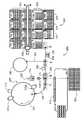
図3および4に示した二連容器からなる測定容器を用いた本発明の自動分析装置100の一例を図5に示す。測定容器収納手段110は、内容物を凍結乾燥状態で収容し封入した測定容器が載置されており、具体的には反応試薬を収容した測定容器(TC)の収納トレイ111、標準品を収容した測定容器(CAL)の収納トレイ112、精度管理試料を収容した測定容器(CTL)の収納トレイ113、検体希釈液を収容した測定容器(DIL)の収納トレイ114、および前処理試薬を収容した測定容器(PRE)の収納トレイ115を収納している。測定容器収納手段110に載置された測定容器は、測定容器搬送手段116で測定容器を受け入れ位置Aに搬送する。測定容器搬送手段116は、測定容器収納手段110の全体をカバーする水平面内で互いに直交するX軸・Y軸と、垂直方向のZ軸とからなるXYZ軸を自在に動くことができ、容器をピックアップまたは載置するための吸引搬送機構、挟持機構、その他のチャック機構を備えている。さらに測定容器搬送手段116は、各収納トレイの縁部および各測定容器に付された検査項目や試薬種別の識別情報を光学的に読み取るセンサ(図5には不図示)および容器の有無を検知するセンサ(図5には不図示)を備えている。さらに測定容器搬送手段116は、測定容器供給手段110にある各測定容器の配置情報を記憶するための測定容器在庫マッピング手段(図5には不図示)のセンサ機能も備えている。自動分析装置100は、各検体について分析しようとする検査項目を対応付けたワークリストが要求する測定容器を前記マッピング手段から検索し、測定容器搬送手段116により目的の測定容器を所定の受け入れ位置Aに搬送する。
FIG. 5 shows an example of the
図5に示すように受け入れ位置Aは、測定容器移送ブロック120に設けた二つの測定容器保持部121の両方が到達しうる軌道の一方の端部に位置する。測定容器移送ブロック120は、測定容器保持部121に載置された測定容器が受け入れ位置Aから位置Eを経由して分注位置Bに移送され、さらに二つの測定容器保持部121の両方が到達しうる軌道の他方の端部に位置する搬送中継点Cまで移送されるように往復動可能な、直線軌道上を移動することができる。また、測定容器移送ブロック120に振動を付与する駆動手段(図5には不図示)を設けることにより、測定容器内の凍結乾燥物の溶解・混合を促進することができる。前記振動を付与する駆動手段は、分注位置B、搬送中継点Cまたはその間の軌道上に備えると好ましい。
As shown in FIG. 5, the receiving position A is located at one end of a track that can be reached by both of the two measurement
図5に示すように、受け入れ位置Aと位置Eとの間の軌道上には、測定容器に付された識別コードを最終的に確認するための識別コード読取手段130およびシール破開手段140を備えている。分注手段150は、分注チップ供給部151、分注水供給部152、検体供給部153および分注位置Bを結ぶ軌道上を自在に動くことができるノズル154を備えている。前記分注手段150は、ノズル154を分注チップ供給部151まで搬送し分注チップをノズル154に装着し、分注水供給部152まで搬送後、分注水を吸引する。その後検体供給部153まで搬送して検体を吸引し、分注位置Bまで搬送することで分注位置Bに位置する測定容器中へ分注水と検体の混合液を分注することができる。分注位置Bで検体を注入された測定容器は、測定容器移送ブロック120により搬送中継点Cまで移送された後、測定容器搬送手段161により反応手段170に備えた反応テーブル171上の位置Dへ搬送される。位置Dへ搬送された測定容器は反応テーブル171により、一定温度調節のもとに所定の時間をかけて第1のB/F分離手段(洗浄手段)172aの位置まで搬送される。第1のB/F分離手段(洗浄手段)172aは過剰の検体を固相から分離し、引き続き標識試薬分注手段173により標識試薬が分注される。標識試薬が分注された測定容器は、さらに所定の時間をかけて第2のB/F分離手段(洗浄手段)172bの位置まで搬送され、過剰の標識試薬が固相から分離される。免疫反応終了(第2のB/F分離終了)後の測定容器は再び位置Dまで搬送された後、測定容器移送手段161により搬送中継点C上にある測定容器移送ブロック120の測定容器保持部121へ搬送される。前記搬送された測定容器は分注位置Bを経て、基質分注手段180を備えた位置で基質が分注される。基質が分注された測定容器は測定容器移送ブロック120により位置Eまで移送された後、測定容器搬送手段162により検出手段190へ搬送される。
As shown in FIG. 5, on the track between the receiving position A and the position E, an identification code reading means 130 and a seal breaking means 140 for finally confirming the identification code attached to the measurement container are provided. I have. The dispensing
次に、本発明の試薬キットとして図3および4に示した二連容器からなる測定容器を用い、自動分析装置100として図5に示す装置を用いたときの、搬送工程および分注工程を各ステップごとに詳細に説明する(図6から9)。測定試料(検体)、標準品、精度管理試料、希釈検体および前処理検体の測定は、自動分析装置100に備えた測定容器移送ブロック120と分注手段150との動作タイミングの組み合わせにより、自動的に測定することができる。
Next, each of the transporting step and the dispensing step when the measuring container comprising the double container shown in FIGS. 3 and 4 is used as the reagent kit of the present invention and the apparatus shown in FIG. Each step will be described in detail (FIGS. 6 to 9). Measurement samples (samples), standard products, quality control samples, diluted samples, and pre-processed samples are automatically measured by a combination of operation timings of the measurement
図6は、測定試料(検体)を反応試薬で直接測定する場合における、測定容器収納手段から測定容器を受け入れ位置Aに載置してから、測定容器を反応テーブル171上の位置Dに搬送するまでの搬送工程および分注工程の各ステップと、測定容器移送ブロック120の動作とを関連づけた図である。なお、識別コード読取手段およびシール破開手段の作動工程は省略した。
FIG. 6 shows that when a measurement sample (specimen) is directly measured with a reaction reagent, the measurement container is placed at the receiving position A from the measurement container storage means, and then the measurement container is transferred to the position D on the reaction table 171. It is the figure which linked | related the operation | movement of the measurement
まず、測定容器移送ブロック120に設けた二つの測定容器保持部のうち一方の保持部が受け入れ位置Aに位置するように測定容器移送ブロック120を移送後、反応試薬を収容した測定容器(TC)を前記測定容器保持部に載置する(ステップS11)。次に、載置した測定容器が分注位置Bに位置するように測定容器移送ブロック120を移送後、TCのうち、固相試薬を収容したウェルに分注水および検体を、標識試薬を収容したウェルに分注水を、それぞれ分注手段150により分注し、凍結乾燥試薬を溶解する(ステップS12)。なお、標識試薬の溶解は分注位置Bの前後(例えば基質分注手段と並設した位置)または反応テーブル171での初期の移送位置に別途分注水分注機構を備え、実施してもよい。そして、TCが搬送中継点Cに位置するように測定容器移送ブロック120を移送(ステップS13)後、TCを測定容器搬送手段によって測定容器移送ブロック120からピックアップし、反応テーブル171上の位置Dへ搬送する(ステップS14)。
First, a measurement container (TC) containing a reaction reagent after transferring the measurement
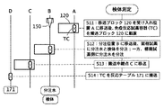
図7は、標準品または精度管理試料を測定する場合における、測定容器収納手段から測定容器を受け入れ位置Aに載置してから、測定容器を反応テーブル171上の位置Dに搬送するまでの搬送工程および分注工程の各ステップと、測定容器移送ブロック120の動作とを関連づけた図である。
FIG. 7 shows the transport from when the measurement container is placed at the receiving position A from the measurement container storage means to when the measurement container is transported to the position D on the reaction table 171 when measuring a standard product or a quality control sample. It is the figure which linked | related the step of the process and the dispensing process, and operation | movement of the measurement
まず、測定容器移送ブロック120に設けた二つの測定容器保持部のうち左側の保持部が受け入れ位置Aに位置するように測定容器移送ブロック120を移送後、標準品を収容した測定容器(CAL)または精度管理試料を収容した測定容器(CTL)を前記左側の保持部に載置する(ステップS21)。次に、測定容器移送ブロック120に設けた二つの測定容器保持部のうち右側の保持部が受け入れ位置Aに位置するように測定容器移送ブロック120を移送後、TCを前記右側の保持部に載置する(ステップS22)。次に、CALまたはCTL(前記左側の保持部)が分注位置Bに位置するように測定容器移送ブロック120を移送し、分注水を分注手段150により分注することで凍結乾燥された標準品または精度管理試料を溶解後、前記溶解液(測定試料)を分注手段150により吸引する(ステップS23)。次に、TC(前記右側の保持部)が分注位置Bに位置するように測定容器移送ブロック120を移送し、TCのうち、固相試薬を収容したウェルに前記分注手段150により吸引した溶解液(測定試料)を吐出し、標識試薬を収容したウェルに分注水を分注手段150により分注する(ステップS24)。なお、図6の場合と同様、標識試薬の溶解は分注位置Bの前後(例えば基質分注手段と並設した位置)または反応テーブル171での初期の移送位置に別途分注水分注機構を備え、実施してもよい。そして、TCが搬送中継点Cに位置するように測定容器移送ブロック120を移送(ステップS25)後、TCを測定容器搬送手段によって測定容器移送ブロック120からピックアップし、反応テーブル171上の位置Dへ搬送する(ステップS26)。なお、標準品または精度管理試料を測定する際は、濃度の異なる複数の標準品または精度管理試料を測定するため、別の標準品または精度管理試料について再びステップS21を実行することになる(ステップS27)。
First, a measurement container (CAL) containing a standard product after transferring the measurement
図8は、検体希釈液を収容した測定容器(DIL)を用いて検体を希釈してから測定する場合における、測定容器収納手段から測定容器を受け入れ位置Aに載置してから、測定容器を反応テーブル171上の位置Dに搬送するまでの搬送工程および分注工程の各ステップと、測定容器移送ブロック120の動作とを関連づけた図である。標準品または精度管理試料を測定する場合は、CALまたはCTLに分注水を分注して得られた溶解液を測定試料としたが、希釈した検体を測定する場合は、DILに分注水および検体を分注し得られた溶解液を測定試料とする。
FIG. 8 shows a case where the measurement container is placed in the receiving position A from the measurement container storage means when the measurement is performed after diluting the sample using the measurement container (DIL) containing the sample diluent. It is the figure which linked | related the step of the conveyance process and dispensing process until it conveys to the position D on the reaction table 171, and the operation | movement of the measurement
まず、測定容器移送ブロック120に設けた二つの測定容器保持部のうち左側の保持部が受け入れ位置Aに位置するように測定容器移送ブロック120を移送後、DILを前記左側の保持部に載置する(ステップS31)。次に、測定容器移送ブロック120に設けた二つの測定容器保持部のうち右側の保持部が受け入れ位置Aに位置するように測定容器移送ブロック120を移送後、TCを前記右側の保持部に載置する(ステップS32)。
次に、DIL(前記左側の保持部)が分注位置Bに位置するように測定容器移送ブロック120を移送し、DILのうち、一方のウェルに分注水および検体を分注手段150により分注することで凍結乾燥された検体希釈液の溶解および検体の希釈を行なった後、前記希釈された検体(測定試料)を分注手段150により吸引する(ステップS33)。なお、2段階目(追加)の希釈を行なう場合は、DILのうち、他方のウェルに前記希釈された検体と分注水を分注手段150により分注することで凍結乾燥された検体希釈液の溶解および検体の再希釈を行なった後、得られた再希釈された検体を分注手段150により吸引すればよい。次に、TC(前記右側の保持部)が分注位置Bに位置するように測定容器移送ブロック120を移送し、TCのうち、固相試薬を収容したウェルに前記分注手段150により吸引した希釈(または再希釈)された検体(測定試料)を吐出し、標識試薬を収容したウェルに分注水を分注手段150により分注する(ステップS34)。なお、図6の場合と同様、標識試薬の溶解は分注位置Bの前後(例えば基質分注手段と並設した位置)または反応テーブル171での初期の移送位置に別途分注水分注機構を備え、実施してもよい。そして、TCが搬送中継点Cに位置するように測定容器移送ブロック120を移送(ステップS35)後、TCを測定容器搬送手段によって測定容器移送ブロック120からピックアップし、反応テーブル171上の位置Dへ搬送する(ステップS36)。
First, after the measurement
Next, the measurement
図9は、測定試料(検体)を、前処理試薬を収容した測定容器(PRE)を用いて前処理してから測定する場合における、測定容器収納手段から測定容器を受け入れ位置Aに載置してから、測定容器を反応テーブル171上の位置Dに搬送するまでの搬送工程および分注工程の各ステップと、測定容器移送ブロック120の動作とを関連づけた図である。検体を前処理してから測定する方法の一例として、前処理試薬1(変性剤)で検体を処理したものを反応手段に備えた反応テーブルで所定時間反応した後、前処理試薬2(中和剤)で処理してから測定する方法があり、図9では前記方法で測定を行なう場合の説明図である。
FIG. 9 shows that the measurement container is placed in the receiving position A from the measurement container storage means when the measurement sample (specimen) is measured after pretreatment using the measurement container (PRE) containing the pretreatment reagent. 10 is a diagram in which each step of the transport process and the dispensing process until the measurement container is transported to position D on the reaction table 171 and the operation of the measurement
まず、測定容器移送ブロック120に設けた二つの測定容器保持部のうち左側の保持部が受け入れ位置Aに位置するように測定容器移送ブロック120を移送後、PREを前記左側の保持部に載置する(ステップS41)。次に、測定容器移送ブロック120に設けた二つの測定容器保持部のうち右側の保持部が受け入れ位置Aに位置するように測定容器移送ブロック120を移送後、TCを前記右側の保持部に載置する(ステップS42)。次に、PRE(前記左側の保持部)が分注位置Bに位置するように測定容器移送ブロック120を移送し、PREのうち、前処理試薬1を収容したウェルに分注水および検体を分注手段150により分注することで凍結乾燥された前処理試薬の溶解および検体の一次処理を行なう(ステップS43)。次に、PRE(前記左側の保持部)が搬送中継点Cに位置するように測定容器移送ブロック120を移送する(ステップS44)。次に、PREを測定容器移送手段によって測定容器移送ブロック120からピックアップし、反応テーブル171上の位置Dへ搬送後、所定時間(例えば十数分間)反応させる(ステップS45)。次に、前記反応した検体を収容したPREを測定容器搬送手段によって搬送中継点Cに位置する測定容器移送ブロック120の左側の保持部に載置する(ステップS46)。次に、PRE(前記左側の保持部)が再び分注位置Bに位置するように測定容器移送ブロック120を移送後、前処理試薬1で一次処理した検体を分注手段150により吸引し、前処理試薬2を収容したウェルに吐出することで凍結乾燥された前処理試薬の溶解および検体の二次処理を行なった後、前記二次処理した検体(測定試料)を分注手段150により吸引する(ステップS47)。次に、TC(前記右側の保持部)が分注位置Bに位置するように測定容器移送ブロック120を移送し、TCのうち、固相試薬を収容したウェルに前記分注手段150により吸引した二次処理した検体(測定試料)を吐出し、標識試薬を収容したウェルに分注水を分注手段150により分注する(ステップS48)。なお、図6の場合と同様、標識試薬の溶解は分注位置Bの前後(例えば基質分注手段と並設した位置)または反応テーブル171での初期の移送位置に別途分注水分注機構を備え、実施してもよい。そして、TCが搬送中継点Cに位置するように測定容器移送ブロック120を移送(ステップS49)後、TCを測定容器移送手段によって測定容器移送ブロック120からピックアップし、反応テーブル171上の位置Dへ搬送する(ステップS50)。
First, after the measurement
図6から9の方法で反応テーブル171上に搬送されたTCは、一定温度調節のもとに所定の反応時間経過後、第1のB/F分離、標識試薬の分注、第2のB/F分離、基質分注を経て標識された目的成分の検出工程に至る。なお、前述した実施形態は2ステップサンドイッチ法の免疫測定であるが、1ステップサンドイッチ法、液相反応を優先させたサンドイッチ法、競合測定法その他の公知の免疫測定法に対しても本発明の試薬キットが有用であることは明らかである。 The TC transported on the reaction table 171 by the method of FIGS. 6 to 9 is subjected to the first B / F separation, the dispensing of the labeling reagent, the second B after the predetermined reaction time has elapsed under constant temperature control. The process of detecting the target component labeled through / F separation and substrate dispensing is reached. The above-described embodiment is an immunoassay of a two-step sandwich method, but the present invention is also applicable to a one-step sandwich method, a sandwich method prioritizing a liquid phase reaction, a competitive measurement method, and other known immunoassays. Clearly, reagent kits are useful.
10、30:測定容器
11:アルミ箔シール
11a、21、31a、41:識別コード
20、40:測定容器収納トレイ
32a、32b:ウェル
100:自動分析装置
110:測定容器収納手段
111:測定容器収納トレイ(反応試薬用)
112:測定容器収納トレイ(標準品用)
113:測定容器収納トレイ(精度管理試料用)
114:測定容器収納トレイ(希釈液用)
115:測定容器収納トレイ(前処理試薬用)
116、161、162:測定容器搬送手段
120:測定容器移送ブロック
121:測定容器保持部
130:識別コード読取手段
140:シール破開手段
150:分注手段
151:分注チップ供給部
152:分注水供給部
153:検体供給部
154:ノズル
170:反応手段
171:反応テーブル
172a、172b:洗浄手段
173:標識試薬分注手段
180:基質分注手段
190:検出手段
10, 30: Measurement container 11:
112: Measuring container storage tray (for standard products)
113: Measuring container storage tray (for quality control sample)
114: Measurement container storage tray (for diluent)
115: Measurement container storage tray (for pretreatment reagent)
116, 161, 162: Measurement container transport means 120: Measurement container transfer block 121: Measurement container holding part 130: Identification code reading means 140: Seal breaking means 150: Dispensing means 151: Dispensing tip supply part 152: Dispensing water Supply unit 153: Specimen supply unit 154: Nozzle 170: Reaction means 171: Reaction table 172a, 172b: Washing means 173: Labeling reagent dispensing means 180: Substrate dispensing means 190: Detection means
Claims (8)
(2)標準品の構成成分を収容した測定容器、精度管理試料の構成成分を収容した測定容器、検体希釈液の構成成分を収容した測定容器、検体を前処理する前処理試薬を収容した測定容器、のうちの少なくとも一つ以上と、
を備えた試薬キットであって、
前記反応試薬を収容した測定容器、前記標準品の構成成分を収容した測定容器、前記精度管理試料の構成成分を収容した測定容器、前記検体希釈液の構成成分を収容した測定容器、および前記検体を前処理する前処理試薬を収容した測定容器の外部形状がいずれも同一である、前記キット。 (1) a measurement container containing a reaction reagent;
(2) Measurement container containing the standard component, measurement container containing the quality control sample component, measurement container containing the sample diluent component, measurement containing the pretreatment reagent for pretreatment of the sample At least one of the containers, and
A reagent kit comprising:
A measurement container containing the reaction reagent, a measurement container containing the components of the standard product, a measurement container containing the components of the quality control sample, a measurement container containing the components of the specimen diluent, and the sample The kit described above, wherein the external shapes of the measurement containers containing the pretreatment reagents for pretreating are all the same.
(2)標準品の構成成分を収容した測定容器を複数載置した測定容器収納トレイ、精度管理試料の構成成分を収容した測定容器を複数載置した測定容器収納トレイ、検体希釈液の構成成分を収容した測定容器を複数載置した測定容器収納トレイ、検体を前処理する前処理試薬を収容した測定容器を複数載置した測定容器収納トレイ、のうちの少なくとも一つ以上と、
を備えた試薬キットであって、
前記反応試薬を収容した測定容器、前記標準品の構成成分を収容した測定容器、前記精度管理試料の構成成分を収容した測定容器、前記検体希釈液の構成成分を収容した測定容器および前記検体を前処理する前処理試薬を収容した測定容器の外部形状がいずれも同一であり、
前記反応試薬を収容した測定容器を複数載置するための測定容器収納トレイ、前記標準品の構成成分を収容した測定容器を複数載置するための測定容器収納トレイ、前記精度管理試料の構成成分を収容するための測定容器を複数載置するための測定容器収納トレイ、前記検体希釈液の構成成分を収容するための測定容器を複数載置するための測定容器収納トレイ、および前記検体を前処理する前処理試薬を収容するための測定容器を複数載置するための測定容器収納トレイの外部形状がいずれも同一である、前記キット。 (1) a measurement container storage tray on which a plurality of measurement containers containing reaction reagents are placed;
(2) Measurement container storage tray on which a plurality of measurement containers containing standard constituent components are placed, measurement container storage tray on which a plurality of measurement containers containing constituent components of a quality control sample are placed, and constituent components of a sample diluent And at least one of a measurement container storage tray in which a plurality of measurement containers containing a pretreatment reagent for preprocessing a sample are placed,
A reagent kit comprising:
A measurement container containing the reaction reagent, a measurement container containing the components of the standard product, a measurement container containing the components of the quality control sample, a measurement container containing the components of the specimen diluent, and the sample The external shape of the measurement container containing the pretreatment reagent to be pretreated is the same,
Measurement container storage tray for mounting a plurality of measurement containers containing the reaction reagent, measurement container storage tray for mounting a plurality of measurement containers storing the components of the standard product, components of the quality control sample A measurement container storage tray for mounting a plurality of measurement containers for storing the sample, a measurement container storage tray for mounting a plurality of measurement containers for storing the components of the sample diluent, and the sample in front The kit, wherein the external shapes of the measurement container storage trays for mounting a plurality of measurement containers for storing pretreatment reagents to be processed are the same.
測定容器を搬送する搬送手段と、
測定容器に液体を吸引/吐出する分注手段と、
測定容器に収容した溶液を反応させる反応手段と、
測定容器に収容した溶液からの光を検出する検出手段と、
を備えた自動分析装置であって、
収納手段に収納する測定容器が、請求項1から5のいずれかに記載のキットに備えた測定容器である、前記自動分析装置。 Storage means for storing the measurement container;
Conveying means for conveying the measurement container;
Dispensing means for sucking / discharging liquid into the measuring container;
A reaction means for reacting the solution contained in the measurement container;
Detection means for detecting light from the solution contained in the measurement container;
An automatic analyzer equipped with
The automatic analyzer, wherein the measurement container stored in the storage means is the measurement container provided in the kit according to any one of claims 1 to 5.
収納手段に収納された測定容器を搬送する第一の搬送手段と、
測定容器に液体を吸引/吐出する分注手段と、
測定容器に収容した溶液を反応させる反応手段と、
測定容器を反応手段へ搬送する第二の搬送手段と、
測定容器に収容した溶液からの光を検出する検出手段と、
測定容器を検出手段へ搬送する第三の搬送手段と、
第一の搬送手段で搬送された測定容器を受け入れ、前記測定容器を、第二の搬送手段で反応手段へ搬送する位置、第三の搬送手段で検出手段へ搬送する位置、および分注手段で検体および/または分注水を吸引/吐出する位置へ移送可能な移送手段と、
を備えた自動分析装置。 Storage means for storing the measurement container provided in the kit according to any one of claims 1 to 5,
First transport means for transporting the measurement container stored in the storage means;
Dispensing means for sucking / discharging liquid into the measuring container;
A reaction means for reacting the solution contained in the measurement container;
A second transport means for transporting the measurement container to the reaction means;
Detection means for detecting light from the solution contained in the measurement container;
A third transport means for transporting the measurement container to the detection means;
Accept the measurement container transported by the first transport means, position to transport the measurement container to the reaction means by the second transport means, position to transport to the detection means by the third transport means, and dispensing means Transport means capable of transporting the specimen and / or dispensed water to a position for aspirating / discharging;
Automatic analyzer equipped with.
反応試薬を収容した測定容器を載置するための測定容器保持部と、
標準品の構成成分を収容した測定容器、精度管理試料の構成成分を収容した測定容器、検体希釈液の構成成分を収容した測定容器、検体を前処理する前処理試薬を収容した測定容器、のいずれかを載置するための測定容器保持部と、
を設けた手段である、請求項7に記載の自動分析装置。 The transport means is
A measurement container holding part for placing a measurement container containing a reaction reagent,
A measurement container containing a standard component, a measurement container containing a quality control sample component, a measurement container containing a sample diluent component, and a measurement container containing a pretreatment reagent for pretreating a sample A measurement container holding part for placing any one of them,
The automatic analyzer according to claim 7, which is means provided with
Priority Applications (1)
| Application Number | Priority Date | Filing Date | Title |
|---|---|---|---|
| JP2010251632A JP2012103097A (en) | 2010-11-10 | 2010-11-10 | Reagent kit and autoanalyzer equipped with the same |
Applications Claiming Priority (1)
| Application Number | Priority Date | Filing Date | Title |
|---|---|---|---|
| JP2010251632A JP2012103097A (en) | 2010-11-10 | 2010-11-10 | Reagent kit and autoanalyzer equipped with the same |
Related Child Applications (2)
| Application Number | Title | Priority Date | Filing Date |
|---|---|---|---|
| JP2014090169A Division JP2014167482A (en) | 2014-04-24 | 2014-04-24 | Reagent kit and automatic analyzer including the same |
| JP2014147676A Division JP5811244B2 (en) | 2014-07-18 | 2014-07-18 | Reagent kit and automatic analyzer equipped with the same |
Publications (1)
| Publication Number | Publication Date |
|---|---|
| JP2012103097A true JP2012103097A (en) | 2012-05-31 |
Family
ID=46393679
Family Applications (1)
| Application Number | Title | Priority Date | Filing Date |
|---|---|---|---|
| JP2010251632A Pending JP2012103097A (en) | 2010-11-10 | 2010-11-10 | Reagent kit and autoanalyzer equipped with the same |
Country Status (1)
| Country | Link |
|---|---|
| JP (1) | JP2012103097A (en) |
Cited By (5)
| Publication number | Priority date | Publication date | Assignee | Title |
|---|---|---|---|---|
| JP2013024691A (en) * | 2011-07-20 | 2013-02-04 | Hitachi High-Technologies Corp | Autoanalyzer |
| JP2014219361A (en) * | 2013-05-10 | 2014-11-20 | 東ソー株式会社 | Container accommodation tray, and automatic analyzer mountable with the same |
| JP2015230205A (en) * | 2014-06-04 | 2015-12-21 | 東ソー株式会社 | Automatic analyzer for executing automatic cleaning of nozzle |
| JP2017096978A (en) * | 2013-03-14 | 2017-06-01 | ジェン−プローブ・インコーポレーテッド | Systems, methods, and apparatuses for performing automated reagent-based assays |
| CN110869769A (en) * | 2017-06-14 | 2020-03-06 | 株式会社日立高新技术 | Test kit, test method, and dispensing device |
Citations (5)
| Publication number | Priority date | Publication date | Assignee | Title |
|---|---|---|---|---|
| JPS6315164A (en) * | 1986-07-07 | 1988-01-22 | Tosoh Corp | Test pack selective supply apparatus of biochemical analyzer |
| JPH08500189A (en) * | 1993-06-03 | 1996-01-09 | ベックマン インスツルメンツ インコーポレーテッド | Sample segment |
| JPH1062432A (en) * | 1996-06-14 | 1998-03-06 | Tosoh Corp | Automatic specimen pretreatment apparatus and method therefor |
| JP2001165936A (en) * | 1999-12-09 | 2001-06-22 | Tosoh Corp | Analytical apparatus |
| JP2002503346A (en) * | 1998-02-20 | 2002-01-29 | スタルト ディアグノステクス ゲゼルシヤフト・ミット・ベシュレンクテル・ハフツング | Analysis system |
-
2010
- 2010-11-10 JP JP2010251632A patent/JP2012103097A/en active Pending
Patent Citations (5)
| Publication number | Priority date | Publication date | Assignee | Title |
|---|---|---|---|---|
| JPS6315164A (en) * | 1986-07-07 | 1988-01-22 | Tosoh Corp | Test pack selective supply apparatus of biochemical analyzer |
| JPH08500189A (en) * | 1993-06-03 | 1996-01-09 | ベックマン インスツルメンツ インコーポレーテッド | Sample segment |
| JPH1062432A (en) * | 1996-06-14 | 1998-03-06 | Tosoh Corp | Automatic specimen pretreatment apparatus and method therefor |
| JP2002503346A (en) * | 1998-02-20 | 2002-01-29 | スタルト ディアグノステクス ゲゼルシヤフト・ミット・ベシュレンクテル・ハフツング | Analysis system |
| JP2001165936A (en) * | 1999-12-09 | 2001-06-22 | Tosoh Corp | Analytical apparatus |
Cited By (6)
| Publication number | Priority date | Publication date | Assignee | Title |
|---|---|---|---|---|
| JP2013024691A (en) * | 2011-07-20 | 2013-02-04 | Hitachi High-Technologies Corp | Autoanalyzer |
| JP2017096978A (en) * | 2013-03-14 | 2017-06-01 | ジェン−プローブ・インコーポレーテッド | Systems, methods, and apparatuses for performing automated reagent-based assays |
| JP2014219361A (en) * | 2013-05-10 | 2014-11-20 | 東ソー株式会社 | Container accommodation tray, and automatic analyzer mountable with the same |
| JP2015230205A (en) * | 2014-06-04 | 2015-12-21 | 東ソー株式会社 | Automatic analyzer for executing automatic cleaning of nozzle |
| CN110869769A (en) * | 2017-06-14 | 2020-03-06 | 株式会社日立高新技术 | Test kit, test method, and dispensing device |
| CN110869769B (en) * | 2017-06-14 | 2023-11-03 | 株式会社日立高新技术 | Test suite, test method and dispensing device |
Similar Documents
| Publication | Publication Date | Title |
|---|---|---|
| US11125766B2 (en) | Automated diagnostic analyzers having rear accessible track systems and related methods | |
| JP5378859B2 (en) | Sample testing system | |
| US20190302135A1 (en) | Sample pretreatment apparatus, robotic arm, and sample pretreatment method | |
| CN110873807A (en) | Sample rack | |
| JPH0894636A (en) | Device and method for automatically analyzing analyte | |
| JP2000275255A (en) | Automatic measuring device | |
| JP2012103097A (en) | Reagent kit and autoanalyzer equipped with the same | |
| EP2626707B1 (en) | Sample treatment system | |
| JP2005539234A (en) | How to increase the throughput of an automated clinical analyzer system by segmenting the assay according to the frequency of work required | |
| JP2018189633A (en) | Vessel carrier for an automated analysis system | |
| EP2746774A1 (en) | System and method for testing liquid samples | |
| CN109459576A (en) | Vitro diagnosis assays method and system | |
| JP5991003B2 (en) | Container supply device and automatic analyzer equipped with the same | |
| JP5811244B2 (en) | Reagent kit and automatic analyzer equipped with the same | |
| JP2014167482A (en) | Reagent kit and automatic analyzer including the same | |
| EP3171177A1 (en) | Method and laboratory system for distributing biological samples onto microplates | |
| CN107179414B (en) | Method for mixing liquids in an automatic analyzer | |
| AU2021277634B2 (en) | Assay apparatuses, consumables and methods | |
| JP2007155746A (en) | Automated analyzer | |
| JP5321324B2 (en) | Automatic analyzer capable of switching reaction vessel supply means | |
| JP7357750B2 (en) | reagent container | |
| JP7319093B2 (en) | Analysis equipment | |
| JP2020176913A (en) | Analysis system, analysis method, and analysis program | |
| WO2022213047A1 (en) | Diagnostic instruments having sorting capability and sorting methods thereof |
Legal Events
| Date | Code | Title | Description |
|---|---|---|---|
| A621 | Written request for application examination |
Free format text: JAPANESE INTERMEDIATE CODE: A621 Effective date: 20131023 |
|
| A977 | Report on retrieval |
Free format text: JAPANESE INTERMEDIATE CODE: A971007 Effective date: 20140228 |
|
| A131 | Notification of reasons for refusal |
Free format text: JAPANESE INTERMEDIATE CODE: A131 Effective date: 20140304 |
|
| A02 | Decision of refusal |
Free format text: JAPANESE INTERMEDIATE CODE: A02 Effective date: 20140708 |