JP2012058704A - Sound recording device, sound recording condition setting method and sound recording condition setting program - Google Patents
Sound recording device, sound recording condition setting method and sound recording condition setting program Download PDFInfo
- Publication number
- JP2012058704A JP2012058704A JP2010204941A JP2010204941A JP2012058704A JP 2012058704 A JP2012058704 A JP 2012058704A JP 2010204941 A JP2010204941 A JP 2010204941A JP 2010204941 A JP2010204941 A JP 2010204941A JP 2012058704 A JP2012058704 A JP 2012058704A
- Authority
- JP
- Japan
- Prior art keywords
- processing
- recording
- types
- scene
- unit
- Prior art date
- Legal status (The legal status is an assumption and is not a legal conclusion. Google has not performed a legal analysis and makes no representation as to the accuracy of the status listed.)
- Pending
Links
Images


Landscapes
- Obtaining Desirable Characteristics In Audible-Bandwidth Transducers (AREA)
- Circuit For Audible Band Transducer (AREA)
- Stereophonic Arrangements (AREA)
Abstract
Description
この発明は、録音装置、録音条件設定方法および録音条件設定プログラムに関し、特に、複数のマイクロホンを備えた録音装置、その録音装置で実行される録音条件設定方法および録音条件設定プログラムに関する。 The present invention relates to a recording apparatus, a recording condition setting method, and a recording condition setting program, and more particularly to a recording apparatus having a plurality of microphones, a recording condition setting method and a recording condition setting program executed by the recording apparatus.
指向性のマイクロホンと無指向性のマイクロホンとを備え、指向性のマイクロホンからの音声信号を記録する録音条件と無指向性のマイクロホンからの音声信号を記録する録音条件とに切換可能な音声記録再生装置が、特開2004−254074号公報(特許文献1)に記載されている。 Audio recording / playback with a directional microphone and an omnidirectional microphone that can be switched between recording conditions for recording audio signals from directional microphones and recording conditions for recording audio signals from omnidirectional microphones An apparatus is described in JP-A-2004-254074 (Patent Document 1).
しかしながら、録音条件の切換は、ユーザが音の発生する発声源を判断し、指向性のマイクロホンと無指向性のマイクロホンとのいずれが音声信号を記録するのに適しているかを判断しなければならない。また、従来は、録音条件を切り換えるために、メニュー画面などからその下位の階層に配置された録音条件を切り換えるための画面を表示させて、録音条件を切り換えなければならず、録音条件を切り換えるための操作が煩雑になるといった問題があった。
この発明は、上述した問題点を解決するためになされたもので、この発明の目的の1つは、録音条件を設定する操作を容易にした録音装置を提供することである。 The present invention has been made to solve the above-described problems, and one of the objects of the present invention is to provide a recording apparatus that facilitates an operation for setting recording conditions.
この発明の他の目的は、録音条件を設定する操作を容易にした録音条件設定方法を提供することである。 Another object of the present invention is to provide a recording condition setting method that facilitates an operation for setting recording conditions.
この発明の他のさらに目的は、録音条件を設定する操作を容易にした録音条件設定プログラムを提供することである。 Another object of the present invention is to provide a recording condition setting program that facilitates an operation for setting a recording condition.
上述した目的を達成するためにこの発明のある局面によれば、録音装置は、指向性を有し、集音した音を出力する複数のマイクロホンと、複数のマイクロホンそれぞれが指向する方向を、予め定めた複数の方向パターンのいずれかに切り換える切換手段と、複数の方向パターンのうち切換手段により切り換えられた方向パターンを検出する検出手段と、複数のマイクロホンにより集音される音に複数種類の処理を実行し、処理された音を記録する録音手段と、録音手段が複数種類の処理を実行するためのパラメータを設定する設定手段と、複数の方向パターンそれぞれに対して、録音手段が複数種類の処理を実行するために用いるパラメータを複数種類の処理ごとに関連付けて記憶する記憶手段と、を備え、設定手段は、検出手段により切換手段により切り換えられた方向パターンが検出される場合、該方向パターンに関連付けられている複数種類の処理を実行するためのパラメータに設定する。 In order to achieve the above-described object, according to one aspect of the present invention, a recording apparatus has a directivity, a plurality of microphones that output collected sound, and a direction in which each of the plurality of microphones is directed in advance. Switching means for switching to any one of a plurality of defined direction patterns; Detection means for detecting a direction pattern switched by the switching means among the plurality of direction patterns; and multiple types of processing for sounds collected by the plurality of microphones Recording means for recording the processed sound, setting means for setting parameters for the recording means to execute a plurality of types of processing, and a plurality of types of recording means for each of the plurality of direction patterns. Storage means for associating and storing parameters used for executing processing for each of a plurality of types of processing, and the setting means is switched by the detecting means. When the direction pattern has been switched by the step is detected, it sets the parameters for performing a plurality of types of processing associated with the direction pattern.
この局面に従えば、複数のマイクロホンそれぞれが指向する方向が予め定めた複数の方向パターンのいずれかに切り換えられると、切り換えられた方向パターンが検出され、複数のマイクロホンにより集音される音に複数種類の処理を実行するために用いるパラメータが、検出された方向パターンに関連付けられている複数種類の処理を実行するためのパラメータに設定される。このため、ユーザは複数のマイクロホンそれぞれが指向する方向を、複数の方向パターンのいずれかに切り換える操作だけで、複数のマイクロホンにより集音される音に複数種類の処理を実行するために用いるパラメータを設定することができる。その結果、録音条件を設定する操作を容易にした録音装置を提供することができる。 According to this aspect, when the direction in which each of the plurality of microphones is directed is switched to one of a plurality of predetermined direction patterns, the switched direction pattern is detected, and a plurality of sounds collected by the plurality of microphones are detected. Parameters used for executing the types of processing are set as parameters for executing a plurality of types of processing associated with the detected direction pattern. For this reason, the user can set parameters used to execute a plurality of types of processing on the sound collected by the plurality of microphones only by switching the direction in which each of the plurality of microphones is directed to one of the plurality of direction patterns. Can be set. As a result, it is possible to provide a recording apparatus that facilitates an operation for setting recording conditions.
好ましくは、設定手段は、検出手段により切換手段により切り換えられた方向パターンが検出される場合、ユーザによる切換指示を受け付ける切換指示受付手段を含み、切換指示が受け付けられることを条件に、検出された方向パターンに関連付けられている複数種類の処理を実行するためのパラメータに設定する。 Preferably, the setting means includes a switching instruction receiving means for receiving a switching instruction by a user when the direction pattern switched by the switching means is detected by the detecting means, and is detected on the condition that the switching instruction is received. Set as a parameter to execute multiple types of processing associated with the direction pattern.
この局面に従えば、切り換えられた方向パターンが検出される場合、ユーザによる切換指示が受け付けられることを条件に、検出された方向パターンに関連付けられている複数種類の処理を実行するためのパラメータに設定される。このため、方向パターンを切り換えた後に、切換指示が受け付けられなければ、対応テーブルにより検出された方向パターンに関連付けられた複数種類の処理を実行するためのパラメータに設定されないので、複数のマイクロホンそれぞれが指向する方向だけを切り換えることができる。 According to this aspect, when a switched direction pattern is detected, parameters for executing a plurality of types of processing associated with the detected direction pattern are provided on the condition that a switching instruction from the user is accepted. Is set. For this reason, if the switching instruction is not accepted after switching the direction pattern, it is not set as a parameter for executing a plurality of types of processing associated with the direction pattern detected by the correspondence table. Only the direction of the direction can be switched.
好ましくは、記憶手段は、複数の方向パターンの数以上の複数のシーンそれぞれに対して、録音手段が複数種類の処理を実行するために用いるパラメータを複数種類の処理ごとに関連付けて記憶し、複数の方向パターンそれぞれは、複数のシーンのいずれか1つに対応付けられ、ユーザによる少なくとも1つのシーンのうちから1つの選択を受け付ける選択受付手段を、さらに備え、設定手段は、選択受付手段によりユーザによる選択が受け付けられることに応じて、複数のシーンのうちユーザにより選択されたシーンに関連付けられている複数種類の処理を実行するためのパラメータに設定する。 Preferably, the storage means stores, for each of a plurality of scenes equal to or more than the number of direction patterns, the parameters used by the recording means for executing a plurality of types of processing in association with each of the plurality of types of processing Each of the direction patterns is associated with any one of a plurality of scenes, and further comprises selection accepting means for accepting one selection from at least one scene by the user, and the setting means is selected by the selection accepting means. In response to accepting the selection by, the parameter is set to a parameter for executing a plurality of types of processing associated with the scene selected by the user among the plurality of scenes.
この局面に従えば、ユーザによる少なくとも1つのシーンのうちから1つの選択が受け付けられることに応じて、複数のシーンのうちユーザにより選択されたシーンに関連付けられている複数種類の処理を実行するためのパラメータに設定される。このため、ユーザは複数のシーンのうちから1つを選択する操作をすれば、複数のマイクロホンそれぞれが指向する方向と関係なく、複数のマイクロホンにより集音される音に複数種類の処理を実行するために用いるパラメータを設定することができる。 According to this aspect, in response to accepting one selection from at least one scene by the user, to execute a plurality of types of processing associated with the scene selected by the user among the plurality of scenes Parameter. For this reason, if the user performs an operation of selecting one of a plurality of scenes, a plurality of types of processing are executed on the sound collected by the plurality of microphones regardless of the direction in which each of the plurality of microphones is directed. The parameters used for this purpose can be set.
好ましくは、ユーザによる変更指示を受け付ける変更指示受付手段と、受け付けられた変更指示に従って、複数のシーンそれぞれに関連付けられている複数種類の処理を実行するためのパラメータを変更する変更手段とをさらに備える。 Preferably, the information processing apparatus further includes a change instruction receiving unit that receives a change instruction from a user, and a changing unit that changes parameters for executing a plurality of types of processing associated with each of a plurality of scenes according to the received change instruction. .
この局面に従えば、複数のシーンそれぞれに対して、複数種類の処理ごとに関連付けられているパラメータを、ユーザの好みにあった値に変更することができる。 According to this aspect, for each of a plurality of scenes, parameters associated with a plurality of types of processing can be changed to values that suit the user's preference.
好ましくは、複数種類の処理は、マイク感度を調整するマイク感度調整処理、入力レベルを適切なレベルに調節するオートレベルコントロール処理と、低域の音を補正する低域補正処理と、低域の音をカットするローカットフィルタ処理、音声信号を符号化する符号化処理、音量レベルを所定の値以下にする録音ピークリミッタ処理、予め定められた時刻に録音を開始するセルフタイマ処理および無音の部分をカットするVAS処理のうちから選ばれた少なくとも1つを含む。 Preferably, the plurality of types of processing include microphone sensitivity adjustment processing for adjusting microphone sensitivity, auto level control processing for adjusting the input level to an appropriate level, low frequency correction processing for correcting low frequency sound, and low frequency processing. Low cut filter processing to cut the sound, encoding processing to encode the audio signal, recording peak limiter processing to make the volume level below a predetermined value, self-timer processing to start recording at a predetermined time, and silence part At least one selected from the VAS processes to be cut is included.
この発明の他の局面によれば、録音条件設定方法は、指向性を有し、集音した音を出力する複数のマイクロホンと、複数のマイクロホンそれぞれが指向する方向を、予め定めた複数の方向パターンのいずれかに切り換える切換手段と、を備えた録音装置で実行される録音条件設定方法であって、複数の方向パターンのうち切換手段により切り換えられた方向パターンを検出するステップと、複数のマイクロホンにより集音される音に複数種類の処理を実行し、処理された音を記憶手段に記憶するステップと、録音するステップにおいて複数種類の処理を実行するためのパラメータを設定するステップと、複数の方向パターンそれぞれに対して、録音するステップにおいて複数種類の処理を実行するために用いるパラメータを複数種類の処理ごとに関連付けて記憶するステップと、を含み、設定するステップは、検出するステップにおいて切換手段により切り換えられた方向パターンが検出される場合、該検出された方向パターンに関連付けられている複数種類の処理を実行するためのパラメータに設定するステップと含む。 According to another aspect of the present invention, a recording condition setting method has a directivity, a plurality of microphones that output collected sound, and a direction in which each of the plurality of microphones is directed to a plurality of predetermined directions. A recording condition setting method executed by a recording device comprising: a switching means for switching to any one of patterns; a step of detecting a direction pattern switched by the switching means among a plurality of direction patterns; and a plurality of microphones Performing a plurality of types of processing on the sound collected by the step, storing the processed sound in the storage means, setting parameters for performing the plurality of types of processing in the recording step, and a plurality of steps For each direction pattern, the parameters used to execute multiple types of processing in the recording step are used for multiple types of processing. And the step of setting, when the direction pattern switched by the switching means is detected in the detecting step, a plurality of types of processing associated with the detected direction pattern are performed. And setting to parameters for execution.
この局面に従えば、録音条件を設定する操作を容易にした録音条件設定方法を提供することができる。 According to this aspect, it is possible to provide a recording condition setting method that facilitates an operation for setting a recording condition.
この発明のさらに他の局面によれば、録音条件設定プログラムは、指向性を有し、集音した音を出力する複数のマイクロホンと、複数のマイクロホンそれぞれが指向する方向を、予め定めた複数の方向パターンのいずれかに切り換える切換手段と、を備えた録音装置を制御するコンピュータで実行される録音条件設定プログラムであって、複数の方向パターンのうち切換手段により切り換えられた方向パターンを検出するステップと、複数のマイクロホンにより集音される音に複数種類の処理を実行し、処理された音を記憶手段に記憶するステップと、録音するステップにおいて複数種類の処理を実行するためのパラメータを設定するステップと、複数の方向パターンそれぞれに対して、録音するステップにおいて複数種類の処理を実行するために用いるパラメータを複数種類の処理ごとに関連付けて記憶するステップと、をコンピュータに実行させ、設定するステップは、検出するステップにおいて切換手段により切り換えられた方向パターンが検出される場合、該方向パターンに関連付けられている複数種類の処理を実行するためのパラメータに設定するステップと含む。 According to still another aspect of the present invention, the recording condition setting program has a plurality of microphones having directivity and outputting collected sounds, and a plurality of predetermined directions in which each of the plurality of microphones is directed. A recording condition setting program executed by a computer for controlling a recording apparatus comprising a switching means for switching to any one of the direction patterns, and detecting a direction pattern switched by the switching means among a plurality of direction patterns A plurality of types of processing is performed on the sound collected by the plurality of microphones, and parameters for executing the plurality of types of processing are set in the step of storing the processed sound in the storage unit and the step of recording A plurality of types of processing are executed in the recording step for each of the step and the plurality of direction patterns. The step of causing the computer to execute and set the step of associating and storing the parameters used for each of the plurality of types of processing when the direction pattern switched by the switching means is detected in the detecting step. And a step of setting parameters for executing a plurality of types of processing associated with.
この局面に従えば、録音条件を設定する操作を容易にした録音条件設定プログラムを提供することができる。 According to this aspect, it is possible to provide a recording condition setting program that facilitates an operation for setting recording conditions.
以下、本発明の実施の形態について図面を参照して説明する。以下の説明では同一の部品には同一の符号を付してある。それらの名称および機能も同じである。したがってそれらについての詳細な説明は繰返さない。 Hereinafter, embodiments of the present invention will be described with reference to the drawings. In the following description, the same parts are denoted by the same reference numerals. Their names and functions are also the same. Therefore, detailed description thereof will not be repeated.
図1は、ICレコーダの平面図である。図1を参照して、ICレコーダ1は、集音部5と、LCD(Liquid Crystal Display)65と、操作部7とを含む。なお、図中の点線および矢印は、説明のために付したもので、実際には存在しない。LCD65は、ICレコーダ1の正面に設けられ、画像を表示する。また、画像を表示可能であれば、LCD65に代えて、有機ELD(Electroluminescence Display)等のディスプレイを用いるようにしてもよい。
FIG. 1 is a plan view of the IC recorder. Referring to FIG. 1,
操作部7は、ICレコーダ1の正面に配置された複数のハードキーを含み、複数のハードキーそれぞれは通常はOFFであるが、ユーザにより押下されるとONになる。複数のハードキーは、第1ファンクションボタン9と、第2ファンクションボタン10と、停止ボタン13と、録音ボタン15と、コントロールボタン17と、決定ボタン19と、リストボタン21と、メニューボタン23とを含む。
The
第1ファンクションボタン9および第2ファンクションボタン10それぞれは、LCD65の所定の位置に表示されるソフトキーに対応する。操作部7は、ユーザが第1ファンクションボタン9を押下すると、第1ファンクションボタン9に対応するソフトキーが押下されたことを示す信号を出力する。ユーザが第2ファンクションボタン10を押下すると、第2ファンクションボタン10に対応するソフトキーが押下されたことを示す信号を出力する。このため、LCD65に複数種類のソフトキーを表示することができる。
Each of the
録音ボタン15は、録音の開始を指示する操作が割り当てられたボタンである。決定ボタン19は、音の再生を指示する操作が割り当てられたボタンである。停止ボタン13は、音の再生の停止を支持する操作が割り当てられたボタンである。リストボタン21は、録音された音データの名称の一覧および/または音データを格納するフォルダの名称の一覧の表示を指示する操作が割り当てられたボタンである。メニューボタン23は、メニュー画面の表示を指示する操作が割り当てられたボタンである。メニュー画面は、ICレコーダ1が有する複数の機能を実行するための設定値を設定するための複数の設定画面を表示させるための画面であり、複数の機能の名称が選択可能に一覧表示される画面である。複数の機能は、録音機能、再生機能、ファイル編集機能を含む。
The
コントロールボタン17は、上ボタン17Aと、下ボタン17Bと、右ボタン17Cと、左ボタン17Dとを含む。上ボタン17A、下ボタン17B、右ボタン17Cおよび左ボタン17Dは、LCD65に表示される選択肢を選択する操作、LCD65に表示される画面を切り換える操作等を受け付ける。
The
集音部5は、ダイヤル25と、第1指向性マイクロホン45と、第2指向性マイクロホン47と、無指向性マイクロホン49とを備える。ダイヤル25は、LCD65の表示面に垂直な回転軸を中心に回転可能に集音部5に取り付けられている。ダイヤル25は、集音部5の外側に突出する突起部26を有する。突起部26は、集音部5の外側に突出するので、ユーザは、突起部26に触れることができ、さらに、突起部26に力を加えることによりダイヤル25を回転させることができる。なお、図1においては、ダイヤル25の一部が集音部5の外部に出ているが、少なくとも突起部26が集音部5の外部に突出していればよい。
The
ダイヤル25が回転することによりダイヤル25の位置が変化する。ここでは、ダイヤル25が取り得る位置のうち予め定められた3つの位置を、第1位置、第2位置および第3位置とする。図1では、ダイヤル25が第1位置にあるときの突起部26を実線で示し、ダイヤル25が第2位置にあるときの突起部26Aを点線で示し、ダイヤル25が第3位置にあるときの突起部26Bを点線で示している。第2位置は、ダイヤル25が第1位置を起点として回転軸を中心に反時計回りに所定の角度だけ回転した位置である。第3位置は、ダイヤル25が第1位置を起点として回転軸を中心に時計回りに所定の角度だけ回転した位置である。なお、所定の角度は、180度よりも小さい。
As the
第1指向性マイクロホン45は、その指向方向(以下、「第1指向方向」という)が回転軸45Aに対して垂直となるように回転可能に集音部5に取り付けられている。第2指向性マイクロホン47は、その指向方向(以下、「第2指向方向」という)が回転軸47Aに対して垂直となるように回転可能に集音部5に取り付けられている。また、第1指向性マイクロホン45および第2指向性マイクロホン47それぞれの回転軸45A,47Aは、ダイヤル25の回転軸と平行であり、第1指向性マイクロホン45および第2指向性マイクロホン47それぞれは、ダイヤル25と、例えば歯車等で機構的に連結されており、ダイヤル25の回転に連動して回転する。
The first
したがって、第1指向性マイクロホン45および第2指向性マイクロホン47それぞれが指向する方向は、ダイヤル25の回転に連動して変化し、ダイヤル25の位置に対する第1指向方向および第2指向方向はそれぞれ1つに定まる。ここでは、第1指向方向および第2指向方向の組み合わせを方向パターンといい、ダイヤル25の第1位置に対する方向パターンを第1方向パターン、ダイヤル25の第2位置に対する方向パターンを第2方向パターンといい、ダイヤル25の第3位置に対する方向パターンを第3方向パターンという。
Therefore, the direction in which each of the first
図2は、第1方向パターンの一例を示す図である。図2を参照して、第1指向性マイクロホン45は、回転軸45Aを中心に回転可能であり、第2指向性マイクロホン47は、回転軸47Aを中心に回転可能である。点線で示され、第1指向性マイクロホン45に向かう矢印は第1指向方向を示す。点線で示され、第2指向性マイクロホン47に向かう矢印は第2指向方向を示す。第1方向パターンは、第1指向方向と第2指向方向とが平行である。このため、第1方向パターンにおいて第1指向性マイクロホン45および第2指向性マイクロホン47それぞれは、同じ方向で発生する音を集音する場合、例えば、複数人の前で人が話す場合など、前方等所定の方向の音を集音するのに適している。
FIG. 2 is a diagram illustrating an example of the first direction pattern. Referring to FIG. 2, the first
図3は、第2方向パターンの一例を示す図である。図3を参照して、第1指向性マイクロホン45に向かう点線で示される矢印は第1指向方向を示し、第2指向性マイクロホン47に向かう点線で示される矢印は第2指向方向を示す。第2方向パターンは、第1指向方向が第1方向パターンにおける第1指向方向から反時計回りに所定角度回転した方向であり、第2指向方向が第1方向パターンにおける第2指向方向から時計回りに所定角度回転した方向である。このため、第2方向パターンにおいて、第1指向性マイクロホン45が図中の上方よりも右側で発生する音を集音し、第2指向性マイクロホン47が図中上方よりも左側で発生する音を集音する。このため、例えば前方等所定の方向よりも右側または左側で発生する音を集音する場合、例えば、左右に存在する複数人が会話する場合など左右の方向で発生する音を集音するのに適している。
FIG. 3 is a diagram illustrating an example of the second direction pattern. Referring to FIG. 3, an arrow indicated by a dotted line toward the first
図4は、第3方向パターンの一例を示す図である。図4を参照して、第1指向性マイクロホン45に向かう点線で示される矢印は第1指向方向を示し、第2指向性マイクロホン47に向かう点線で示される矢印は第2指向方向を示す。第3方向パターンは、第1指向方向が第1方向パターンにおける第1指向方向から時計回りに所定角度回転した方向であり、第2指向方向が第1方向パターンにおける第2指向方向から反時計回りに所定角度回転した方向である。このため、第3方向パターンにおいて、第1指向性マイクロホン45が図中上方よりも左側で発生する音を集音し、第2指向性マイクロホン47が図中上方よりも右側で発生する音を集音する。第3方向パターンは、第2方向パターンにおいて第1指向性マイクロホン45および第2指向性マイクロホン47が集音する音の方向が逆になる。このため、第1指向性マイクロホン45が出力する音声信号を左側のチャンネルLchの音とし、第2指向性マイクロホン47が出力する音声信号を右側のチャンネルRchの音として録音するように、後述するコーデック31において内部処理する。さらに、第3方向パターンは、第2方向パターンと異なり、第1指向性マイクロホン45が集音可能な音源の範囲と、第2指向性マイクロホン47が集音可能な音源の範囲とが一部で重なる。したがって、音源の範囲が重なる部分の音源の音を、定位感を向上させることができる。したがって、第3方向パターンは、前方等所定の方向よりも右側または左側で発生する音を集音するのに加えて、前方で発生する音を定位感のあるとして集音する場合、例えば、ボーカルが中央に立ってバンド演奏する場合など、左右の方向の音および前方からの音を集音するのに適している。
FIG. 4 is a diagram illustrating an example of the third direction pattern. Referring to FIG. 4, an arrow indicated by a dotted line toward the first
なお、本実施の形態においては、第1指向性マイクロホン45の回転軸45Aが第1指向性マイクロホン45を通り、第2指向性マイクロホン47の回転軸47Aが第2指向性マイクロホン47を通る場合を示したが、第1指向性マイクロホン45の回転軸45Aおよび第2指向性マイクロホン47の回転軸47Aは、互いに平行であれば、第1指向性マイクロホン45および第2指向性マイクロホン47を通る必要はない。
In the present embodiment, the
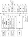
図5は、ICレコーダのハードウェア構成の概要を示す機能ブロック図である。図5を参照して、ICレコーダ1は、ICレコーダ1の全体を制御するための中央演算装置(CPU)11と、それぞれがCPU11とバス69で接続された、コーデック31と、エンコーダ/デコーダ43と、RAM(Random Access Memory)51と、スピーカ53と、ヘッドホン端子55と、外部メモリコントローラ57と、EEPROM(Electrically Erasable and Programmable Read Only Memory)59と、シリアルインターフェース(I/F)61と、ROM63と、LCD65と、位置検出センサ67とを含む。
FIG. 5 is a functional block diagram showing an outline of the hardware configuration of the IC recorder. Referring to FIG. 5, the
RAM51は、CPU11の作業領域として用いられる。ROM63は、CPU11が実行するプログラム等を記憶する。EEPROM59は、圧縮された音声信号等を不揮発的に記憶するための内部メモリである。外部メモリコントローラ57は、メモリカード57Aが接続される。CPU11は、外部メモリコントローラ57を介して、それに接続されたメモリカード57Aにアクセスが可能である。
The
シリアルインターフェース61は、シリアル通信可能な装置と接続される。CPU11は、シリアルインターフェース61を介して、それに接続された装置と通信が可能である。ヘッドホン端子55は、ヘッドホンまたはイヤホン等が接続され、それらにアナログの音声信号を出力する。スピーカ53は、アナログの音声信号が入力され、音声を出力する。
The
コーデック31は、第1指向性マイクロホン45と、第2指向性マイクロホン47と、無指向性マイクロホン49と、が接続される。コーデック31は、第1指向性マイクロホン45および第2指向性マイクロホン47から入力されるアナログの音声信号、または、第1指向性マイクロホン45、第2指向性マイクロホン47および無指向性マイクロホン49から入力されるアナログの音声信号をデジタル信号に変換し、所定の信号処理をした後に、デジタル処理後の音声信号をCPU11に出力する。デジタル処理後の音声信号は、左右2チャンネルのオーディオ信号である。
The
コーデック31は、デジタル信号を処理するために、オートレベルコントロール(ALC)部33、感度調整部35、ローカットフィルタ部37、低域補正部39および録音ピークリミッタ部41を有する。
The
ALC部33は、CPU11からの指示に基づいて、処理対象とする音声信号の入力レベルを自動で調整するALC処理を実行する。例えば、ALC部33は、高い音域と低い音域の入力レベルを調整する。具体的には、ALC部33は、CPU11からオートレベルコントロールを有効にする指示が入力されると、処理対象とする音声信号の入力レベルを調整し、オートレベルコントロールを無効にする指示が入力されると、処理対象とする音声信号の入力レベルを調整しない。
The
感度調整部35は、CPU11からの指示に基づいて、第1指向性マイクロホン45、第2指向性マイクロホン47および無指向性マイクロホン49それぞれの感度を高い感度または低い感度のいずれかに調整するマイク感度調整処理を実行する。具体的には、感度調整部35は、CPU11から高感度にする指示が入力されると、第1指向性マイクロホン45、第2指向性マイクロホン47および無指向性マイクロホン49それぞれの感度を高くし、低感度にする指示が入力されると、第1指向性マイクロホン45、第2指向性マイクロホン47および無指向性マイクロホン49それぞれの感度を低くする。
The
ローカットフィルタ部37は、CPU11からの指示に基づいて、処理対象とする音声信号の低い帯域の音をカットするローカットフィルタ処理を実行する。具体的には、ローカットフィルタ部37は、CPU11からローカットフィルタを有効にする指示が入力されると、処理対象とする音声信号の低い帯域の音をカットし、ローカットフィルタを無効にする指示が入力されると、処理対象とする音声信号の低い帯域の音をカットしない。
Based on an instruction from the
低域補正部39は、CPU11からの指示に基づいて、処理対象とする音声信号の音声帯域の低域部分を補正する低域補正処理を実行する。具体的には、低域補正部39は、CPU11から低域補正を有効にする指示が入力されると、処理対象とする音声信号の低域部分を補正するが、低域補正を無効にする指示が入力されると、処理対象とする音声信号の低域部分を補正しない。低域補正部39は、低域補正処理を実行する場合、第1指向性マイクロホン45および第2指向性マイクロホン47それぞれから出力される音声信号の低域部分を、無指向性マイクロホン49から出力される音声信号で補間することにより、低域補正する。第1指向性マイクロホン45および第2指向性マイクロホン47の特性として、低域部分が、他の帯域部分よりも感度が低いからである。低域補正部39は、低域補正処理を実行しない場合、第1指向性マイクロホン45および第2指向性マイクロホン47から出力される音声信号のみを出力する。
Based on an instruction from the
録音ピークリミッタ部41は、CPU11からの指示に基づいて、処理対象とする音声信号の音量レベルを所定の値以下にする録音ピークリミッタ処理を実行する。具体的には、録音ピークリミッタ部41は、CPU11から録音ピークリミッタを有効にする指示が入力されると、処理対象とする音声信号の音量レベルを所定の値以下にするが、録音ピークリミッタを無効にする指示が入力されると、処理対象とする音声信号の音量レベルを所定の値以下にしない。
The
エンコーダ/デコーダ43は、CPU11により制御され、コーデック31から出力される音声信号を符号化する符号化処理を実行する。また、エンコーダ/デコーダ43は、CPU11により制御され、符号化された音声信号を復号する復号処理を実行する。
The encoder /
第1指向性マイクロホン45、第2指向性マイクロホン47および無指向性マイクロホン49から出力される音声信号は、コーデック31によりデジタル信号に変換される。CPU11は、コーデック31より出力される音声信号を、エンコーダ/デコーダ43に符号化させ、符号化された音声信号を、EEPROM59または外部メモリコントローラ57に接続されたメモリカード57Aに記憶する。また、CPU11は、EEPROM59、または外部メモリコントローラ57に接続されたメモリカード57Aに記憶された音声信号を読み出して、エンコーダ/デコーダ43に復号させ、復号された音声信号をコーデック31にアナログ信号に変換させ、アナログの音声信号を、スピーカ53またはヘッドホン端子55に接続されたヘッドホンに出力する。
Audio signals output from the first
位置検出センサ67は、ダイヤル25の位置を検出し、検出した位置をCPU11に出力する。位置検出センサ67は、例えば、近接スイッチであり、ダイヤル25が第1位置、第2位置および第3位置のいずれにあるかを検出する。具体的には、位置検出センサ67は、ダイヤル25が第1位置に位置することを検出する場合、第1検出信号をCPU11に出力し、ダイヤル25が第2位置に位置する場合第2検出信号をCPU11に出力し、ダイヤル25が第3位置に位置する場合第3検出信号をCPU11に出力する。なお、位置検出センサ67は、エンコーダであってもよい。
The
なお、本実施の形態においては、CPU11が、ROM63に記憶されたプログラムを実行する例を説明するが、EEPROM59、または外部メモリコントローラ57に接続されたメモリカード57Aに記憶されたプログラムを実行するようにしても良い。
In this embodiment, an example in which the
図6は、CPUの機能の概要をEEPROMに記憶されるデータとともに示す機能ブロック図である。図6に示す機能は、CPU11が、ROM59、EEPROM59、またはメモリカード57Aに記憶されたプログラムを実行することにより、CPU11に形成される。図6を参照して、CPU11は、方向パターンを検出する検出部71と、ユーザによるシーンの選択を受け付ける選択受付部73と、録音条件を設定する設定部75と、録音制御部79と、変更指示受付部107と、変更部109と、VAS(Voice Active System)部101と、セルフタイマ部103とを含む。
FIG. 6 is a functional block diagram showing an outline of CPU functions together with data stored in the EEPROM. The functions shown in FIG. 6 are formed in the
VAS部101は、後述するVAS制御部83により制御され、処理対象とする音声信号の無音部分をカットするVAS処理を実行する。VAS部101は、VAS制御部83からVAS処理を有効にする指示が入力されると、VAS処理を実行するが、VAS処理を無効にする指示が入力されると、VAS処理を実行しない。
The
セルフタイマ部103は、後述するセルフタイマ制御部85により制御され、ユーザが録音ボタン15を押して録音準備ができた後、予め定められた時刻になると録音を開始するセルフターマー処理を実行する。セルフタイマ部103は、セルフタイマ制御部85からセルフタイマ処理を有効にする指示が入力されると、セルフタイマ処理を実行するが、セルフタイマ処理を無効にする指示が入力されると、セルフタイマ処理を実行しない。
The self-
検出部71は、位置検出センサ67の出力に基づいて、方向パターンの切換を検出する。上述したように、ユーザがダイヤル25を回転させることにより、ダイヤル25の回転に連動して第1指向方向および第2指向方向が変化し、第1方向パターン、第2方向パターンおよび第3方向パターンのいずれかに切り換わる。第1方向パターンは、ダイヤル25が第1位置の状態に対応し、第2方向パターンは、ダイヤル25が第2位置の状態に対応し、第3方向パターンは、ダイヤル25が第3位置の状態に対応する。このため、検出部71は、位置検出センサ67の出力が第1検出信号に変化すると、第1方向パターンを検出し、第1方向パターンに切り換わったことを示す第1切換信号を設定部75に出力する。検出部71は、位置検出センサ67の出力が第2検出信号に変化すると、第2方向パターンを検出し、第2方向パターンに切り換わったことを示す第2切換信号を設定部75に出力する。検出部71は、位置検出センサ67の出力が第3検出信号に変化すると、第3方向パターンを検出し、第3方向パターンに切り換わったことを示す第3切換信号を設定部75に出力する。
The
選択受付部73は、基本画面をLCD65に表示し、シーン選択指示を受け付ける。図7は、基本画面の一例を示す図である。図7を参照して、基本画面200は、電源がONになったときに最初にLCD65に表示される画面である。基本画面200は、設定されているパラメータの一部を表示する領域203と、シーンボタン201を含む。シーンボタン201は、第1ファンクションボタン9に対応している。領域203は、選択されているシーンに割り当てられたアイコン205を含む。ここでは、アイコン205は、シーン名「音楽」のシーンに割り当てられたアイコン231(図8(C)参照)と同じとしており、シーン名「音楽」のシーンが選択されていることが示される。このため、ユーザは、基本画面200中のアイコン205を見て、選択されているシーンを認識することができる。さらに、図1に示されるように、LCD65の上側に第1指向性マイクロホン45および第2指向性マイクロホン47が配置されているので、ユーザは、LCD65に表示される基本画面200と第1指向性マイクロホン45および第2指向性マイクロホン47とを同時に視認することができる。このため、第1指向性マイクロホン45および第2指向性マイクロホン47の方向パターンと、設定されているパラメータとを一度に確認することができる。
The
図6に戻って、選択受付部73は、基本画面200がLCD65に表示されている状態で、ユーザが第1ファンクションボタン9を押下すると、シーン表示指示を受け付け、4つのシーンそれぞれに対応する4つのシーン選択画面をLCD65に順に表示する。4つのシーンのうち3つのシーンは、「講義」のシーンと、「会議」のシーンと、「音楽」のシーンとを含む。「講義」のシーンは、複数人の前で人が話す場合など前方からの音声を録音するシーンである。「会議」のシーンは、複数人が会話し、全方向からの音声を録音するシーンである。「音楽」のシーンは、音楽演奏や動物の声などを高音質で録音するシーンである。4つのシーンのうち他の1つのシーンは、ユーザがお好みで作成したシーンであり、「お気に入り」のシーンである。なお、本実施の形態においては、4つのシーンの例を示すが、シーンの数はこれに限定されるものではなく、お気に入りシーンの数を増やす等して5つ以上にしてもよいし、4つよりも少なくしても良い。
Returning to FIG. 6, when the user presses the
図8は、シーン選択画面の一例を示す図である。図8(A)は、「講義」のシーンに対応するシーン選択画面を示す図である。図8(A)を参照して、シーン選択画面210は、「講義」の文字列と、複数の前で人が話す講義の様子を表した絵と、シーン名「講義」のシーンに割り当てられたアイコン211と、を含む。図8(B)は、「会議」のシーンに対応するシーン選択画面を示す図である。図8(B)を参照して、シーン選択画面220は、「会議」の文字列と、複数人で会話する会議の様子を表した絵と、シーン名「会議」のシーンに割り当てられたアイコン221と、を含む。図8(C)は、「音楽」のシーンに対応するシーン選択画面を示す図である。図8(C)を参照して、シーン選択画面230は、「音楽」の文字列と、音楽演奏の様子を表した絵と、シーン名「音楽」のシーンに割り当てられたアイコン231と、を含む。図8(D)は、「お気に入り」のシーンに対応するシーン選択画面を示す図である。図8(D)を参照して、シーン選択画面240は、「お気に入り」の文字列と、シーン名「お気に入り」のシーンに割り当てられた絵と、シーン名「お気に入り」のシーンに割り当てられたアイコン241と、を含む。LCD65には、4つのシーン選択画面210,220,230,240のいずれかが表示され、ユーザが右ボタン17Cまたは左ボタン17Dを押下すると、LCD65に表示されるシーン選択画面が順に切り換わる。
FIG. 8 is a diagram illustrating an example of a scene selection screen. FIG. 8A shows a scene selection screen corresponding to the “lecture” scene. Referring to FIG. 8A, the
選択受付部73は、ユーザがコントロールボタン17を操作してシーン選択画面を順に切り換え、決定ボタン19を押下すると、4つのシーン選択画面のうち決定ボタン19が押下された時点で表示されているシーン選択画面に対応するシーンを選択するソーン選択指示を受け付ける。選択受付部73は、シーン選択指示を受け付けると、4つのシーン選択画面のうち決定ボタン19が押下された時点で表示されているシーン選択画面に対応するシーンを識別するためのシーン名を設定部75および変更指示受付部107に出力する。
When the user operates the
設定部75は、検出部71から第1〜第3切換信号のいずれかが入力され、選択受付部73からシーン名が入力される。設定部75は、選択受付部73からシーン名が入力される場合、EEPROM59に記憶された対応テーブルによってシーン名で特定されるシーンに対応して予め定められた複数種類の処理にそれぞれ対応する複数のパラメータを、複数種類の処理を実行するための複数のパラメータとして設定する。複数種類の処理を実行するための複数のパラメータは、録音条件である。複数種類の処理は、エンコーダ/デコーダ43が実行する符号化処理と、ALC部33が実行するALC処理と、感度調整部35が実行するマイク感度調整処理と、ローカットフィルタ部37が実行するローカットフィルタ処理と、低域補正部39が実行する低域補正処理と、録音ピークリミッタ部41が実行する録音ピークリミッタ処理と、VAS部101が実行するVAS処理と、セルフタイマ部103が実行するセルフタイマ処理とを含む。
The setting
図9は、対応テーブルの一例を示す図である。図9を参照して、対応テーブル111は、4つのシーンにそれぞれ対応する4つの対応レコードを含み、シーン名と、複数種類の処理をそれぞれ実行するための複数のパラメータとを対応付ける。対応レコードは、シーンの項目と、圧縮符号化の項目と、マイク感度の項目と、ALCの項目と、低域補正の項目と、ローカットフィルタの項目と、録音ピークリミッタの項目と、セルフタイマの項目と、VASの項目とを含む。シーンの項目には、4つのシーンそれぞれに対応するシーン名「講義」、「会議」「音楽」および「お気に入り」のいずれかが設定される。なお、ここでは、対応テーブル111において、ユーザが設定可能なシーンを「お気に入り」のシーンのみとしたが、「お気に入り」のシーンと同様に、ユーザが複数種類の処理をそれぞれ実行するための複数のパラメータを設定可能な、シーンを2以上設けるようにしてもよい。この場合には、対応テーブル111は、5つ以上の対応レコードを含む。 FIG. 9 is a diagram illustrating an example of the correspondence table. Referring to FIG. 9, correspondence table 111 includes four correspondence records respectively corresponding to four scenes, and associates scene names with a plurality of parameters for executing a plurality of types of processing. Corresponding records include scene items, compression encoding items, microphone sensitivity items, ALC items, low frequency correction items, low cut filter items, recording peak limiter items, and self-timer items. And items of VAS. In the scene item, one of scene names “lecture”, “conference”, “music”, and “favorite” corresponding to each of the four scenes is set. Here, in the correspondence table 111, only the “favorite” scene can be set by the user. However, in the same way as the “favorite” scene, the user can execute a plurality of processes for executing a plurality of types of processing. Two or more scenes in which parameters can be set may be provided. In this case, the correspondence table 111 includes five or more correspondence records.
対応レコードの圧縮符号化の項目には、符号化処理を実行するために用いられるパラメータとして、圧縮レートを示す16bit,44kHz/48kHz/320kbps/192kbps/64kbps/32kbpsのいずれかが設定される。マイク感度の項目には、マイク感度調整処理を実行するために用いられるパラメータとして、マイク感度の高低を示す高および低のいずれかが設定される。ALCの項目には、ALC処理を実行するために用いられるパラメータとして、ALC処理を実行するか否かを示すONおよびOFFのいずれかが設定される。低域補正の項目には、低域補正処理を実行するために用いられるパラメータとして、低域補正処理を実行するか否かを示すONおよびOFFのいずれかが設定される。ローカットフィルタの項目には、ローカットフィルタ処理を実行するために用いられるパラメータとして、ローカットフィルタ処理を実行するか否かを示すONおよびOFFのいずれかが設定される。録音ピークリミッタの項目には、録音ピークリミッタ処理を実行するために用いられるパラメータとして、録音ピークリミッタ処理を実行するか否かを示すONおよびOFFのいずれかが設定される。セルフタイマの項目には、セルフタイマ処理を実行するために用いられるパラメータとして、セルフタイマ処理を実行するか否かを示すONまたはOFFのいずれかが設定される。VASの項目には、VAS処理を実行するために用いられるパラメータとして、VAS処理を実行するか否かを示すONまたはOFFのいずれかが設定される。 In the item of compression encoding of the corresponding record, any of 16 bits, 44 kHz / 48 kHz / 320 kbps / 192 kbps / 64 kbps / 32 kbps indicating the compression rate is set as a parameter used for executing the encoding process. In the microphone sensitivity item, either high or low indicating the microphone sensitivity is set as a parameter used for executing the microphone sensitivity adjustment processing. In the ALC item, one of ON and OFF indicating whether or not to execute the ALC process is set as a parameter used for executing the ALC process. In the low-frequency correction item, either ON or OFF indicating whether or not to execute the low-frequency correction processing is set as a parameter used for executing the low-frequency correction processing. In the item of the low cut filter, either ON or OFF indicating whether or not to execute the low cut filter process is set as a parameter used for executing the low cut filter process. In the recording peak limiter item, either ON or OFF indicating whether or not to execute the recording peak limiter process is set as a parameter used for executing the recording peak limiter process. In the self-timer item, either ON or OFF indicating whether to execute the self-timer process is set as a parameter used to execute the self-timer process. In the VAS item, either ON or OFF indicating whether or not to execute the VAS process is set as a parameter used to execute the VAS process.
例えば、シーンの項目に「講義」が設定された対応レコードは、圧縮符号化の項目にパラメータ「192kbps」が設定され、マイク感度の項目にパラメータ「高」が設定され、ALCの項目にパラメータ「ON」が設定され、低域補正の項目にパラメータ「ON」が設定され、ローカットフィルタの項目にパラメータ「ON」が設定され、録音ピークリミッタの項目にパラメータ「ON」が設定され、セルフタイマの項目にパラメータ「OFF」が設定され、VASの項目にパラメータ「OFF」が設定される。 For example, in a corresponding record in which “Lecture” is set in the scene item, the parameter “192 kbps” is set in the compression encoding item, the parameter “high” is set in the microphone sensitivity item, and the parameter “ ON ”is set, the parameter“ ON ”is set in the low frequency correction item, the parameter“ ON ”is set in the low cut filter item, the parameter“ ON ”is set in the recording peak limiter item, and the self-timer The parameter “OFF” is set in the item, and the parameter “OFF” is set in the VAS item.
図6に戻って、設定部75は、選択受付部73から入力されたシーン名が入力される場合、EEPROM59に記憶されている対応テーブル111に含まれる4つの対応レコードのうちから、選択受付部73から入力されたシーン名がシーンの項目に設定された対応レコードを抽出する。設定部75は、抽出された対応レコードに含まれる複数種類の処理にそれぞれ対応する複数のパラメータを、複数種類の処理を実行するための録音条件としてEEPROM59に記憶する。具体的には、符号化処理を実行するために用いられるパラメータ、マイク感度調整処理を実行するために用いられるパラメータ、ALC処理を実行するために用いられるパラメータ、低域補正処理を実行するために用いられるパラメータ、ローカットフィルタ処理を実行するために用いられるパラメータ、録音ピークリミッタ処理を実行するために用いられるパラメータ、セルフタイマ処理を実行するために用いられるパラメータ、VAS処理を実行するために用いられるパラメータを、録音条件としてEEPROM59に記憶する。ただし、既にEEPROM59に録音条件として複数のパラメータが記憶されている場合、録音条件として記憶されている複数のパラメータに上書きして記憶する。
Returning to FIG. 6, when the scene name input from the
設定部75は、切換指示受付部77を含む。切換指示受付部77は、検出部71から第1〜第3切換信号のいずれかが入力される場合、録音条件を切り換える切換指示を受け付ける。まず、切換指示受付部77は、第1切換信号が入力される場合は第1方向パターンに切り換えられたと判断し、第2切換信号が入力される場合は第2方向パターンに切り換えられたと判断し、第3切換信号が入力される場合は第3方向パターンに切り換えられたと判断する。次に、切換指示受付部77は、EEPROM59に予め記憶された方向パターンテーブルによって、第1〜第3方向パターンのうち検出部71から入力される第1〜第3切換信号によって定まるものに対応して予め定められたシーンを特定する。
Setting
図10は、方向パターンテーブルの一例を示す図である。図10を参照して、方向パターンテーブル113は、3つの方向パターンそれぞれに対応する3つの方向パターンレコードを含み、3つの方向パターンを3つのシーンのいずれかと関連付ける。方向パターンレコードは、方向パターンの項目と、シーンの項目とを含む。方向パターンの項目には方向パターン名が設定され、シーンの項目にはシーン名が設定される。方向パターン名が第1方向パターンはシーン名「講義」と関連付けられる。第1方向パターンとシーン名「講義」とを関連付けるのは、第1方向パターンが「講義」のシーンで録音するのに適しているからである。方向パターン名が第2方向パターンはシーン名「会議」を関連付けられる。第2方向パターンとシーン名「会議」とを関連付けるのは、第2方向パターンが「会議」のシーンで録音するのに適しているからである。方向パターン名が第3方向パターンはシーン名「音楽」と関連付けられる。第3方向パターンと「音楽」のシーンとを関連付けるのは、第3方向パターンが「音楽」のシーンで録音するのに適しているからである。 FIG. 10 is a diagram illustrating an example of a direction pattern table. Referring to FIG. 10, direction pattern table 113 includes three direction pattern records corresponding to the three direction patterns, and associates the three direction patterns with any of the three scenes. The direction pattern record includes a direction pattern item and a scene item. A direction pattern name is set in the direction pattern item, and a scene name is set in the scene item. The direction pattern name of the first direction pattern is associated with the scene name “lecture”. The reason for associating the first direction pattern with the scene name “lecture” is that the first direction pattern is suitable for recording in the scene of “lecture”. The direction name of the second direction pattern is associated with the scene name “conference”. The reason why the second direction pattern is associated with the scene name “conference” is that the second direction pattern is suitable for recording in the “conference” scene. The direction pattern name of the third direction pattern is associated with the scene name “music”. The reason why the third direction pattern is associated with the “music” scene is that the third direction pattern is suitable for recording in the “music” scene.
切換指示受付部77は、方向パターンテーブル113を参照して、第1〜第3切換信号のうち検出部71から入力されたものに対応するシーンを特定すると、特定されたシーンに対応する推奨シーン決定画面をLCD65に表示する。切換指示受付部77は、検出部71から第1切換信号が入力される場合、「講義」のシーンに対応する第1推奨シーン決定画面を表示し、検出部71から第2切換信号が入力される場合、「会議」のシーンに対応する第2推奨シーン決定画面を表示し、検出部71から第3切換信号が入力される場合、「音楽」のシーンに対応する第3推奨シーン決定画面を表示する。
When the switching
図11は、第1推奨シーン決定画面の一例を示す図である。図11を参照して、第1推奨シーン決定画面250は、シーン名「講義」のシーンに割り当てられたアイコン251と、「推奨シーン[講義]」の文字列と、「推奨シーン設定を呼び出しますか?」の文字列と、「はい」の文字列を含む決定キー251と、「いいえ」の文字列を含むキャンセルキー253とを含む。決定キー251は、第1ファンクションボタン9に対応しており、キャンセルキー253は、第2ファンクションボタン10に対応している。ユーザが第1ファンクションボタン9を押下すると、シーン名「講義」のシーンに決定され、ユーザが第2ファンクションボタン10を押下すると、シーン名「講義」のシーンに決定されない。シーン名「講義」のシーンに割り当てられたアイコン251は、図8(A)に示したシーン選択画面210に含まれるアイコン211と同じである。このため、ユーザは、第1推奨シーン決定画面250を見て、シーン名「講義」のシーンに対応するパラメータが設定されることを確認することができる。
FIG. 11 is a diagram illustrating an example of a first recommended scene determination screen. Referring to FIG. 11, the first recommended
図12は、第2推奨シーン決定画面の一例を示す図である。図12を参照して、第2推奨シーン決定画面260は、シーン名「会議」のシーンに割り当てられたアイコン265と、「推奨シーン[会議]」の文字列と、「推奨シーン設定を呼び出しますか?」の文字列と、「はい」の文字列を含む決定キー261と、「いいえ」の文字列を含むキャンセルキー263とを含む。決定キー261は、第1ファンクションボタン9に対応しており、キャンセルキー263は、第2ファンクションボタン10に対応している。ユーザが第1ファンクションボタン9を押下すると、シーン名「会議」のシーンに決定され、ユーザが第2ファンクションボタン10を押下すると、シーン名「会議」のシーンに決定されない。シーン名「会議」のシーンに割り当てられたアイコン265は、図8(B)に示したシーン選択画面220に含まれるアイコン221と同じである。このため、ユーザは、第2推奨シーン決定画面260を見て、シーン名「会議」のシーンに対応するパラメータが設定されることを確認することができる。
FIG. 12 is a diagram illustrating an example of a second recommended scene determination screen. Referring to FIG. 12, the second recommended
図13は、第3推奨シーン決定画面の一例を示す図である。図13を参照して、第3推奨シーン決定画面270は、シーン名「音楽」のシーンに割り当てられたアイコン275と、「推奨シーン[音楽]」の文字列と、「推奨シーン設定を呼び出しますか?」の文字列と、「はい」の文字列を含む決定キー271と、「いいえ」の文字列を含むキャンセルキー273とを含む。決定キー271は、第1ファンクションボタン9に対応しており、キャンセルキー273は、第2ファンクションボタン10に対応している。ユーザが第1ファンクションボタン9を押下すると、シーン名「音楽」のシーンに決定され、ユーザが第2ファンクションボタン10を押下すると、シーン名「音楽」のシーンに決定されない。シーン名「音楽」のシーンに割り当てられたアイコン275は、図8(C)に示したシーン選択画面230に含まれるアイコン231と同じである。このため、ユーザは、第2推奨シーン決定画面260を見て、シーン名「音楽」のシーンに対応するパラメータが設定されることを確認することができる。
FIG. 13 is a diagram illustrating an example of a third recommended scene determination screen. Referring to FIG. 13, the third recommended
図6に戻って、切換指示受付部77は、第1〜第3推奨シーン決定画面のいずれかがLCD65に表示されている状態で、ユーザが第1ファンクションボタン9を押下すると、切換指示を受け付ける。切換指示は、録音条件を、特定されるシーンに対応して、対応テーブル111により定められる複数種類の処理を実行するための複数のパラメータに切り換える指示であり、第1推奨新決定画面がLCD65に表示されている状態で第1ファンクションボタン9が押下される場合は、切換指示はシーン名「講義」を特定し、第2推奨新決定画面がLCD65に表示されている状態で第1ファンクションボタン9が押下される場合は、切換指示はシーン名「会議」を特定し、第3推奨新決定画面がLCD65に表示されている状態で第1ファンクションボタン9が押下される場合は、切換指示はシーン名「音楽」を特定する。
Returning to FIG. 6, the switching
設定部75は、切換指示受付部77が切換指示を受け付けると、ROM63に記憶されている対応テーブル111に含まれる4つの対応レコードのうちから、切換指示により特定されるシーンのシーン名がシーンの項目に設定された対応レコードを抽出する。設定部75は、抽出された対応レコードに含まれる複数種類の処理にそれぞれ対応する複数のパラメータを、録音条件としてEEPROM59に記憶する。ただし、既にEEPROM59に録音条件として複数のパラメータが記憶されている場合、記憶されている複数のパラメータに上書きして記憶する。
When the switching
ユーザがダイヤル25を操作して、ダイヤル25を第1位置、第2位置および第3位置のいずれか切り換えることにより、第1〜第3方向パターンのいずれかが決定され、録音条件として、第1〜第3方向パターンのうち決定されたものに対して予め定められたシーンに対応して、予め定められた複数のパラメータが録音条件として設定される。これにより、ダイヤル25を回転させることにより方向パターンを切り換える簡単な操作で、録音条件を設定することができる。
When the user operates the
一方、ユーザは、コントロールボタン17を操作して4つのシーン選択画面のいずれかを選択し、決定ボタン19を押下すれば、4つのシーン選択画面のうち決定ボタン19が押下された時点で表示されているシーン選択画面に対応するシーンに対応して、予め定められた複数のパラメータが録音条件として設定される。このため、ユーザは、第1指向性マイクロホン45および第2指向性マイクロホン47それぞれの指向方向の組を定める方向パターンとは関係なく、録音条件を設定することができる。このため、予め定められた4つのシーンのいずれかと、第1〜第3方向パターンのいずれかとを組み合わせることができ、複数の条件で録音することができる。
On the other hand, if the user operates the
コーデック31、エンコーダ/デコーダ43、VAS部101およびセルフタイマ部103により、第1指向性マイクロホン45および第2指向性マイクロホン47により出力される音に複数種類の処理を実行し、処理された音を記録する録音部が構成される。録音制御部79は、録音部を制御して複数の処理を実行させ、処理された音をEEPROM59に記憶する。録音制御部79は、符号化制御部81と、VAS制御部83と、セルフタイマ制御部85と、感度調整制御部87と、ALC制御部89と、低域補正制御部91と、ローカットフィルタ制御部93と、録音ピークリミッタ制御部95とを含む。
The
符号化制御部81は、EEPROM59に録音条件として記憶されている複数種類の処理を実行するための複数のパラメータのうち圧縮符号化処理を実行するために用いるパラメータを読み出し、エンコーダ/デコーダ43を制御して、読み出したパラメータで定まるビットレートで音声信号を圧縮する処理を実行させる。
The
VAS制御部83は、EEPROM59に録音条件として記憶されている複数種類の処理を実行するための複数のパラメータのうちVAS処理を実行するために用いるパラメータを読み出す。VAS制御部83は、読み出されたパラメータが「ON」を示す場合、VAS部101にVAS処理を実行させ、無音部分の音声信号をカットさせる。VAS制御部83は、読み出されたパラメータが「OFF」を示す場合、VAS部101にVAS処理を実行させない。
The
セルフタイマ制御部85は、EEPROM59に録音条件として記憶されている複数種類の処理を実行するための複数のパラメータのうちセルフタイマ処理を実行するために用いるパラメータを読み出す。セルフタイマ制御部85は、読み出されたパラメータが「ON」を示す場合、セルフタイマ部103にセルフタイマ処理を有効にする指示を出力し、セルフタイマ処理を実行させる。セルフタイマ制御部85は、読み出されたパラメータが「OFF」を示す場合、セルフタイマ部103にセルフタイマ処理を無効にする指示を出力し、セルフタイマ部103にセルフタイマ処理を実行させない。
The self-
感度調整制御部87は、EEPROM59に録音条件として記憶されている複数種類の処理を実行するための複数のパラメータのうちマイク感度調整処理を実行するために用いるパラメータを読み出す。感度調整制御部87は、読み出されたパラメータが「高」を示す場合、感度調整部35に高感度にする指示を出力し、感度調整部35に、第1指向性マイクロホン45、第2指向性マイクロホン47および無指向性マイクロホン49それぞれの感度を高い感度に調整させる。感度調整制御部87は、読み出されたマイク感度のパラメータが「低」を示す場合、感度調整部35に低感度にする指示を出力し、第1指向性マイクロホン45、第2指向性マイクロホン47および無指向性マイクロホン49それぞれの感度を低い感度に調整させる。
The sensitivity
ALC制御部89は、EEPROM59に録音条件として記憶されている複数種類の処理を実行するための複数のパラメータのうちALC処理を実行するために用いるパラメータを読み出す。ALC制御部89は、読み出されたパラメータが「ON」を示す場合、ALC部33に、オートレベルコントロールを有効にする指示を出力し、ALC部33に音の入力レベルを調整させる。ALC制御部89は、読み出されたパラメータが「OFF」を示す場合、ALC部33に、オートレベルコントロールを無効にする指示を出力し、ALC部33に音の入力レベルを調整させない。
The
低域補正制御部91は、EEPROM59に録音条件として記憶されている複数種類の処理を実行するための複数のパラメータのうち低域補正処理を実行するために用いるパラメータを読み出す。低域補正制御部91は、読み出されたパラメータが「ON」を示す場合、低域補正部39に低域補正を有効にする指示を出力し、低域補正部39に、音声信号の低域部分を補正させる。低域補正制御部91は、読み出されたパラメータが「OFF」を示す場合、低域補正部39に低域補正を無効にする指示を出力し、低域補正部39に音声信号の低域部分を補正させない。
The low-frequency
ローカットフィルタ制御部93は、EEPROM59に録音条件として記憶されている複数種類の処理を実行するための複数のパラメータのうちローカットフィルタ処理を実行するために用いるパラメータを読み出す。ローカットフィルタ制御部93は、読み出されたパラメータが「ON」を示す場合、ローカットフィルタ部37にローカットフィルタを有効にする指示を出力し、ローカットフィルタ部37に、ローカットフィルタを有効にする指示を出力し、ローカットフィルタ部37に低い帯域の音をカットさせる。ローカットフィルタ制御部93は、読み出されたパラメータが「OFF」を示す場合、ローカットフィルタ部37にローカットフィルタを無効にする指示を出力し、ローカットフィルタ部37に低い帯域の音をカットさせない。
The low cut
録音ピークリミッタ制御部95は、EEPROM59に録音条件として記憶されている複数種類の処理を実行するための複数のパラメータのうち録音ピークリミッタ処理を実行するために用いるパラメータを読み出す。録音ピークリミッタ制御部95は、読み出されたパラメータが「ON」を示す場合、録音ピークリミッタ部41にローカットフィルタを有効にする指示を出力し、録音ピークリミッタ部41に音量レベルを所定の値以下にさせる。録音ピークリミッタ制御部95は、読み出されたパラメータが「OFF」を示す場合、録音ピークリミッタ部41にローカットフィルタを無効にする指示を出力し、録音ピークリミッタ部41に音量レベルを調整させない。
The recording peak
変更指示受付部107は、選択受付部73からシーン名が入力される。変更指示受付部107は、ユーザが操作部7を操作してパラメータの設定を変更する指示を入力すると、設定変更指示を受け付ける。変更指示受付部107は、設定変更指示を受け付けると、選択受付部73から入力されたシーン名がシーンの項目に設定された対応レコードをEEPROM59に記憶された対応テーブル111から読み出す。変更指示受付部107は、読み出された対応レコードに設定されている複数種類のパラメータを変更するためのパラメータ設定編集一覧画面をLCD65に表示する。
The change
パラメータ設定編集一覧画面は、複数種類のパラメータの名称と、複数種類のパラメータとを含み、パラメータの変更を受け付けるための画面である。パラメータ設定編集一覧画面において、ユーザは、操作部7を操作することにより、パラメータ名を指定し、指定したパラメータ名に対応するパラメータを変更することが可能である。
The parameter setting edit list screen includes a plurality of types of parameter names and a plurality of types of parameters, and is a screen for accepting parameter changes. In the parameter setting edit list screen, the user can operate the
変更指示受付部107は、パラメータ設定編集一覧画面がLCD65に表示されている状態で、ユーザが操作部7を操作することにより決定ボタン19を押下すると、選択受付部73から入力されたシーン名と、変更されたパラメータの名称と変更後のパラメータとの組と、を変更部109に出力する。
When the user presses the enter button 19 by operating the
変更部109は、変更指示受付部107からシーン名と、パラメータ名とパラメータとの組と、が入力される。変更部109は、EEPROM59に記憶された対応テーブル111に含まれる複数の対応レコードのうち変更指示受付部107から入力されたシーン名がシーンの項目に設定されている対応レコードを、変更されたパラメータの名称と変更後のパラメータとの組に基づいて変更する。これにより、対応テーブル111が更新される。ユーザは、対応テーブル111を変更することができるので、ユーザの使用に適したパラメータを設定することができる。
The
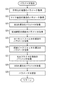
図14は、録音処理の流れの一例を示すフローチャートである。録音処理は、CPU11がROM59、EEPROM59、またはメモリカード57Aに記憶された録音条件設定プログラムを実行することにより、CPU11により実行される処理である。図14を参照して、CPU11は、録音条件としてEEPROM59に既に記憶されている複数種類のパラメータを読み出す(ステップS01)。
FIG. 14 is a flowchart showing an example of the flow of recording processing. The recording process is a process executed by the
次のステップS02においては、図7に示した基本画面200をLCD65に表示する。そして、ステップS03においては、ダイヤル25の位置が切り換えられたか否かを判断する。位置検出センサ67の出力に基づいて、ダイヤル25の位置が切り換えられたか否かを判断する。ダイヤル25の位置が切り換えられたと判断するならば処理をステップS04に進めるが、そうでなければ処理をステップS06に進める。
In the next step S02, the
ステップS04においては、ステップS03において切り換えられた後のダイヤル25の位置を検出する。次のステップS05においては、第1録音設定処理を実行し、処理をステップS08に進める。第1録音設定処理については後述する。一方、ステップS06においては、シーンボタンが押下されたか否かを判断する。図7に示した基本画面200に含まれるシーンボタン201に対応する第1ファンクションボタン9が押下されたならば、シーンボタンが押下されたと判断する。シーンボタンが押下されたならば処理をステップS07に進めるが、そうでなければ処理をステップS08に進める。ステップS07においては、第2録音設定処理を実行し、処理をステップS08に進める。第2録音設定処理については後述する。
In step S04, the position of
ステップS08においては、録音ボタン15が押下されたか否かを判断する。録音ボタン15が押下されたならば、処理をステップS09に進めるが、そうでなければ処理をステップS03に戻す。ステップS09においては、録音を開始する。この場合、EEPROM59に録音条件として記憶された複数種類のパラメータを用いて複数の処理を実行した音声信号をEEPROM59に記憶することにより、録音する。ステップS05およびステップS07が実行されない場合は、ステップS01において読み出されたパラメータに従って複数の処理を実行し、ステップS05が実行される場合には、後述する第1録音設定処理において設定されたパラメータに従って複数の処理を実行し、ステップS07が実行される場合には、後述する第2録音設定処理において設定されたパラメータに従って複数の処理を実行する。次のステップS10においては、ユーザが停止ボタン13を押下すると、録音を終了し、録音処理を終了する。
In step S08, it is determined whether or not the
図15は、第1録音設定処理の流れの一例を示すフローチャートである。第1録音設定処理は、図14のステップS05において実行される処理である。図15を参照して、ステップS11においては、図14のステップS04において検出されたダイヤル25の位置に対応する方向パターンを特定する。次のステップS12においては、ステップS11において特定された方向パターンに対応するシーンを特定する。ROM63に記憶された方向パターンテーブル113において、ステップS11において特定された方向パターンに関連付けられたシーンを特定する。
FIG. 15 is a flowchart showing an example of the flow of the first recording setting process. The first recording setting process is a process executed in step S05 of FIG. Referring to FIG. 15, in step S11, a direction pattern corresponding to the position of
次のステップS13においては、ステップS12において特定されたシーンに対応する推奨シーン決定画面をLCD65に表示する。ステップS12においてシーン名「講義」のシーンが特定される場合、図11に示した第1推奨シーン決定画面250をLCD65に表示し、ステップS12においてシーン名「会議」のシーンが特定される場合、図12に示した第2推奨シーン決定画面260をLCD65に表示し、ステップS12においてシーン名「音楽」のシーンが特定される場合、図13に示した第3推奨シーン決定画面270をLCD65に表示する。
In the next step S13, a recommended scene determination screen corresponding to the scene specified in step S12 is displayed on the
次のステップS14においては、決定ボタン19が押下されたか否かを判断する。決定ボタン19が押下されたならば、処理をステップS16に進めるが、そうでなければ処理をステップS15に進める。ステップS15においては、停止ボタン13が押下されたか否かを判断する。停止ボタン13が押下されたならば、処理をステップS18に進めるが、そうでなければ処理をステップS14に戻す。
In the next step S14, it is determined whether or not the enter button 19 has been pressed. If determination button 19 is pressed, the process proceeds to step S16; otherwise, the process proceeds to step S15. In step S15, it is determined whether or not the
ステップS16においては、EEPROM59に記憶された対応テーブル111に含まれる4つの対応レコードのうちからステップS12において特定されたシーンのシーン名がシーンの項目に設定された対応レコードを選択する。次のステップS17においては、パラメータ設定処理を実行し、処理をステップS18に進める。パラメータ設定処理については後述する。ステップS18においては、基本画面200をLCD65に表示し、処理を録音処理に戻す。
In step S16, a correspondence record in which the scene name of the scene specified in step S12 is set in the scene item is selected from the four correspondence records included in the correspondence table 111 stored in the
図16は、パラメータ設定処理の流れの一例を示すフローチャートである。パラメータ設定処理は、図15のステップS17および後述する図17のステップS35それぞれにおいて実行される処理である。図15のステップS17において実行される場合、図15のステップS16において選択された対応レコードを処理の対象とする。図16を参照して、ステップS21においては、対応レコードの圧縮符号化の項目に設定されているパラメータを、符号化処理を実行するために用いるパラメータとして取得する。ステップS22においては、マイク感度の項目に設定されているパラメータを、マイク感度調整処理を実行するために用いるパラメータとして取得する。ステップS23においては、対応レコードのALCの項目に設定されているパラメータを、ALC処理を実行するために用いるパラメータとして取得する。ステップS24においては、対応レコードの低域補正の項目に設定されているパラメータを、低域補正処理を実行するために用いるパラメータとして取得する。ステップS25においては、対応レコードのローカットフィルタの項目に設定されているパラメータを、ローカットフィルタ処理を実行するために用いるパラメータとして取得する。ステップS26においては、対応レコードの録音ピークリミッタの項目に設定されているパラメータを、録音ピークリミッタ処理を実行するために用いるパラメータとして取得する。ステップS27においては、対応レコードのセルフタイマの項目に設定されているパラメータを、セルフタイマ処理を実行するために用いるパラメータとして取得する。ステップS28においては、対応レコードのVASの項目に設定されているパラメータを、VAS処理を実行するために用いるパラメータとして取得する。 FIG. 16 is a flowchart illustrating an example of the flow of parameter setting processing. The parameter setting process is a process executed in step S17 in FIG. 15 and step S35 in FIG. When executed in step S17 in FIG. 15, the corresponding record selected in step S16 in FIG. Referring to FIG. 16, in step S21, a parameter set in the item of compression encoding of the corresponding record is acquired as a parameter used for executing the encoding process. In step S22, the parameter set in the item of microphone sensitivity is acquired as a parameter used for executing the microphone sensitivity adjustment process. In step S23, the parameter set in the ALC item of the corresponding record is acquired as a parameter used for executing the ALC process. In step S24, the parameters set in the low-frequency correction item of the corresponding record are acquired as parameters used for executing the low-frequency correction processing. In step S25, the parameter set in the item of the low cut filter of the corresponding record is acquired as a parameter used for executing the low cut filter process. In step S26, the parameter set in the recording peak limiter item of the corresponding record is acquired as a parameter used for executing the recording peak limiter process. In step S27, the parameter set in the self-timer item of the corresponding record is acquired as a parameter used for executing the self-timer process. In step S28, the parameter set in the VAS item of the corresponding record is acquired as a parameter used for executing the VAS process.
次のステップS29においては、ステップS21〜ステップS28においてそれぞれ取得されたパラメータを、EEPROM59に録音条件として記憶し、処理を第1録音設定処理に戻す。これにより、符号化処理、マイク感度調整処理、ALC処理、低域補正処理、ローカットフィルタ処理、録音ピークリミッタ処理、セルフタイマ処理、VAS処理それぞれを実行するためのパラメータとして、図15のステップS16において選択された対応レコードにより定められたパラメータが設定される。
In the next step S29, the parameters acquired in steps S21 to S28 are stored in the
図17は、第2録音設定処理の流れの一例を示すフローチャートである。第2録音設定処理は、図14のステップS07において実行される処理である。図17を参照して、ステップS31においては、EEPROM59に記憶された対応テーブル111を読出す。次のステップS32においては、4つのシーン選択画面を1つずつ順にLCD65に順に表示する。具体的には、図8に示した4つのシーン選択画面のうち任意の1つをLCD65に表示し、ユーザがコントロールボタン17の右ボタン17Cまたは左ボタン17Dを押下するごとに、別のシーン選択画面に切り換える。
FIG. 17 is a flowchart showing an example of the flow of the second recording setting process. The second recording setting process is a process executed in step S07 in FIG. Referring to FIG. 17, in step S31, correspondence table 111 stored in
次のステップS33においては、ユーザによりシーンが選択されたか否かを判断する。決定ボタン19の押下を検出すると、シーンを選択する。シーンが選択されたならば、処理をステップS34に進めるが、そうでなければ処理をステップS32に戻す。4つのシーン選択画面のうち決定ボタン19の押下が検出された時にLCD65に表示されているシーン選択画面に対応するシーンを選択する。
In the next step S33, it is determined whether or not a scene has been selected by the user. When pressing of the enter button 19 is detected, a scene is selected. If a scene has been selected, the process proceeds to step S34; otherwise, the process returns to step S32. Of the four scene selection screens, a scene corresponding to the scene selection screen displayed on the
ステップS34においては、ステップS31において読み出された対応テーブル111に含まれる4つの対応レコードのうちステップS33において選択されたシーンのシーン名がシーンの項目に設定された対応レコードを選択する。次のステップS35においては、図16に示したパラメータ設定処理を実行し、処理をステップS36に進める。ステップS35において実行されるパラメータ設定処理は、ステップS34において選択された対応レコードを処理対称とする。ステップS36においては、基本画面200をLCD65に表示し、処理を録音処理に戻す。
In step S34, the correspondence record in which the scene name of the scene selected in step S33 is set as the item of the scene among the four correspondence records included in the correspondence table 111 read in step S31 is selected. In the next step S35, the parameter setting process shown in FIG. 16 is executed, and the process proceeds to step S36. The parameter setting process executed in step S35 makes the corresponding record selected in step S34 symmetrical. In step S36,
ステップS35においてパラメータ設定処理が実行されることにより、符号化処理、マイク感度調整処理、ALC処理、低域補正処理、ローカットフィルタ処理、録音ピークリミッタ処理、セルフタイマ処理、VAS処理それぞれを実行するためのパラメータとして、ステップS34において選択された対応レコードにより定められたパラメータが設定される。 By executing the parameter setting process in step S35, the encoding process, the microphone sensitivity adjustment process, the ALC process, the low frequency correction process, the low cut filter process, the recording peak limiter process, the self timer process, and the VAS process are executed. As the parameters, parameters determined by the corresponding record selected in step S34 are set.
以上説明したように本実施の形態におけるICレコーダ1は、ユーザがダイヤル25を回転させて、第1指向性マイクロホン45および第2指向性マイクロホン47それぞれが指向する方向が予め定めた第1〜第3方向パターンのいずれかに切り換えられると、第1〜第3方向パターンのうちから切り換えられた後の方向パターンを検出する。そして、第1指向性マイクロホン45および第2指向性マイクロホン47により出力される音に、符号化処理、マイク感度調整処理、ALC処理、低域補正処理、ローカットフィルタ処理、録音ピークリミッタ処理、セルフタイマ処理およびVAS処理を含む複数種類の処理それぞれ実行するために用いる複数のパラメータを、第1〜第3方向パターンのうち検出されたものに、対応テーブル111により複数種類の処理ごとに対応付けられたパラメータに設定する。このため、第1指向性マイクロホン45および第2指向性マイクロホン47それぞれが指向する方向を、第1〜第3方向パターンのいずれかに切り換える操作だけで、第1指向性マイクロホン45および第2指向性マイクロホン47よりそれぞれ出力される音に複数種類の処理を実行するために用いるパラメータを設定することができる。
As described above, in the
また、第1〜第3方向パターンのうちいずれかに切り換えられたことが検出される場合、ユーザによる切換指示が受け付けられることを条件に、対応テーブル111により検出された方向パターンに対応付けられた複数種類の処理ごとに対応付けられたパラメータに設定する。このため、第1〜第3方向パターンのうちいずれかに方向パターンを切り換えた後に、切換指示が受け付けられなければ、検出された方向パターンに対応テーブル111により対応付けられた複数種類の処理ごとに対応付けられたパラメータに設定しないので、録音条件を変更することなく、第1指向性マイクロホン45および第2指向性マイクロホン47それぞれが指向する方向だけを切り換えることができる。
Further, when it is detected that one of the first to third direction patterns has been switched, it is associated with the direction pattern detected by the correspondence table 111 on the condition that a switching instruction from the user is accepted. Set to the parameters associated with each type of processing. For this reason, after a direction pattern is switched to any one of the first to third direction patterns, if a switching instruction is not accepted, for each of a plurality of types of processes associated with the detected direction pattern by the correspondence table 111. Since the associated parameter is not set, only the direction in which each of the first
さらに、ユーザが、4つのシーン選択画面210、220,230,240のいずれかがLCD65に表示されている段階で、決定ボタン19を押下すると、4つのシーン選択画面210、220,230,240のうち決定ボタン19が押下された時点で表示されているシーン選択画面に対応するシーンを選択する。そして、ユーザによりシーンが選択されることに応じて、4つのシーンのうちユーザにより選択されたシーンに対して、対応テーブル111により対応付けられた複数種類の処理ごとに対応付けられたパラメータに設定する。このため、ユーザは4つのシーンのうちから1つを選択する操作をすれば、第1指向性マイクロホン45および第2指向性マイクロホン47それぞれが指向する方向と関係なく、第1指向性マイクロホン45および第2指向性マイクロホン47より出力される音に複数種類の処理を実行するために用いるパラメータを設定することができる。
Furthermore, when the user presses the enter button 19 when any of the four scene selection screens 210, 220, 230, 240 is displayed on the
なお、本実施の形態においては、録音装置の一例としてICレコーダ1を例に説明したが、図14〜図17に示した処理をICレコーダ1に実行させる録音条件設定方法、また、その録音条件設定方法をCPU11に実行させる録音条件設定プログラムとして発明を捕らえることができるのはいうまでもない。
In the present embodiment, the
今回開示された実施の形態はすべての点で例示であって制限的なものではないと考えられるべきである。本発明の範囲は上記した説明ではなくて特許請求の範囲によって示され、特許請求の範囲と均等の意味および範囲内でのすべての変更が含まれることが意図される。 The embodiment disclosed this time should be considered as illustrative in all points and not restrictive. The scope of the present invention is defined by the terms of the claims, rather than the description above, and is intended to include any modifications within the scope and meaning equivalent to the terms of the claims.
1 ICレコーダ、5 集音部、7 操作部、11 CPU、25 ダイヤル、26,26A,26B 突起部、31 コーデック、33 ALC部、35 感度調整部、37 ローカットフィルタ部、39 低域補正部、41 録音ピークリミッタ部、43 エンコーダ/デコーダ、45 指向性マイクロホン、45A 回転軸、47 指向性マイクロホン、49 無指向性マイクロホン、45A,47A 回転軸、51 RAM、53 スピーカ、55 ヘッドホン端子、57 外部メモリコントローラ、57A メモリカード、59 EEPROM、61 シリアルインターフェース、63 ROM、65 LCD、67 位置検出センサ、69 バス、71 検出部、73 選択受付部、75 設定部、77 切換指示受付部、79 録音制御部、81 符号化制御部、83 VAS制御部、85 セルフタイマ制御部、87 感度調整制御部、89 ALC制御部、91 低域補正制御部、93 ローカットフィルタ制御部、95 録音ピークリミッタ制御部、101 VAS部、103 セルフタイマ部、107 変更指示受付部、109 変更部、111 対応テーブル、113 方向パターンテーブル、200 基本画面、201 シーンボタン、210,220,230,240 シーン選択画面、250,260,270 第1〜第3推奨シーン決定画面。
1 IC recorder, 5 sound collection unit, 7 operation unit, 11 CPU, 25 dial, 26, 26A, 26B protrusion, 31 codec, 33 ALC unit, 35 sensitivity adjustment unit, 37 low cut filter unit, 39 low frequency correction unit, 41 Recording Peak Limiter, 43 Encoder / Decoder, 45 Directional Microphone, 45A Rotating Axis, 47 Directional Microphone, 49 Nondirectional Microphone, 45A, 47A Rotating Axis, 51 RAM, 53 Speaker, 55 Headphone Terminal, 57 External Memory Controller, 57A memory card, 59 EEPROM, 61 serial interface, 63 ROM, 65 LCD, 67 position detection sensor, 69 bus, 71 detection unit, 73 selection reception unit, 75 setting unit, 77 switching instruction reception unit, 79 recording control unit , 81 Coding control unit, 83 VAS system , 85 Self-timer control unit, 87 Sensitivity adjustment control unit, 89 ALC control unit, 91 Low frequency correction control unit, 93 Low cut filter control unit, 95 Recording peak limiter control unit, 101 VAS unit, 103 Self-timer unit, 107 Instruction accepting unit, 109 changing unit, 111 correspondence table, 113 direction pattern table, 200 basic screen, 201 scene button, 210, 220, 230, 240 scene selection screen, 250, 260, 270 first to third recommended scene determination screens .
Claims (7)
前記複数のマイクロホンそれぞれが指向する方向を、予め定めた複数の方向パターンのいずれかに切り換える切換手段と、
前記複数の方向パターンのうち前記切換手段により切り換えられた方向パターンを検出する検出手段と、
前記複数のマイクロホンにより集音される音に複数種類の処理を実行し、処理された音を記録する録音手段と、
前記録音手段が前記複数種類の処理を実行するためのパラメータを設定する設定手段と、
前記複数の方向パターンそれぞれに対して、前記録音手段が前記複数種類の処理を実行するために用いるパラメータを前記複数種類の処理ごとに関連付けて記憶する記憶手段と、を備え、
前記設定手段は、前記検出手段により前記切換手段により切り換えられた方向パターンが検出される場合、該方向パターンに関連付けられている複数種類の処理を実行するためのパラメータに設定する、録音装置。 A plurality of microphones having directivity and outputting the collected sound;
Switching means for switching the direction in which each of the plurality of microphones is directed to any one of a plurality of predetermined direction patterns;
Detecting means for detecting a direction pattern switched by the switching means among the plurality of direction patterns;
Recording means for performing a plurality of types of processing on the sound collected by the plurality of microphones and recording the processed sound;
Setting means for setting parameters for the recording means to execute the plurality of types of processing;
Storage means for storing, in association with each of the plurality of types of parameters, parameters used by the recording unit for executing the plurality of types of processing for each of the plurality of direction patterns;
When the direction pattern switched by the switching unit is detected by the detection unit, the setting unit sets a parameter for executing a plurality of types of processing associated with the direction pattern.
ユーザによる前記少なくとも1つのシーンのうちから1つの選択を受け付ける選択受付手段を、さらに備え、
前記設定手段は、前記選択受付手段によりユーザによる選択が受け付けられることに応じて、前記複数のシーンのうち前記ユーザにより選択されたシーンに関連付けられている複数種類の処理を実行するためのパラメータに設定する、請求項1または2に記載の録音装置。 The storage means stores, in association with each of the plurality of types of processing, parameters used by the recording unit for executing the plurality of types of processing for each of a plurality of scenes equal to or greater than the number of the plurality of direction patterns. , Each of the plurality of direction patterns is associated with any one of the plurality of scenes,
A selection receiving means for receiving one selection from the at least one scene by the user;
The setting means uses a parameter for executing a plurality of types of processing associated with the scene selected by the user among the plurality of scenes in response to selection by the user being received by the selection receiving means. The recording device according to claim 1, wherein the recording device is set.
前記受け付けられた変更指示に従って、前記複数のシーンそれぞれに対して、前記複数種類の処理ごとに関連付けられたパラメータを変更する変更手段と、をさらに備えた請求1〜3のいずれかに記載の録音装置。 A change instruction receiving means for receiving a change instruction by a user;
4. The recording according to claim 1, further comprising: a changing unit that changes a parameter associated with each of the plurality of types of processing for each of the plurality of scenes according to the received change instruction. apparatus.
前記複数のマイクロホンそれぞれが指向する方向を、予め定めた複数の方向パターンのいずれかに切り換える切換手段と、を備えた録音装置で実行される録音条件設定方法であって、
前記複数の方向パターンのうち前記切換手段により切り換えられた方向パターンを検出するステップと、
前記複数のマイクロホンにより集音される音に複数種類の処理を実行し、処理された音を記憶手段に記憶するステップと、
前記録音するステップにおいて前記複数種類の処理を実行するためのパラメータを設定するステップと、
前記複数の方向パターンそれぞれに対して、前記録音するステップにおいて前記複数種類の処理を実行するために用いるパラメータを前記複数種類の処理ごとに関連付けて記憶するステップと、を含み、
前記設定するステップは、前記検出するステップにおいて前記切換手段により切り換えられた方向パターンが検出される場合、該方向パターンに関連付けられている複数種類の処理を実行するためのパラメータに設定するステップと含む、録音条件設定方法。 A plurality of microphones having directivity and outputting the collected sound;
A recording condition setting method executed by a recording apparatus comprising: a switching unit that switches a direction in which each of the plurality of microphones is directed to one of a plurality of predetermined direction patterns,
Detecting a direction pattern switched by the switching means among the plurality of direction patterns;
Performing a plurality of types of processing on the sound collected by the plurality of microphones, and storing the processed sound in a storage means;
Setting parameters for performing the plurality of types of processing in the recording step;
For each of the plurality of directional patterns, the step of recording the parameters used for executing the plurality of types of processing in the recording step in association with each of the plurality of types of processing,
The setting step includes a step of setting a parameter for executing a plurality of types of processing associated with the direction pattern when the direction pattern switched by the switching unit is detected in the detecting step. , Recording condition setting method.
前記複数のマイクロホンそれぞれが指向する方向を、予め定めた複数の方向パターンのいずれかに切り換える切換手段と、を備えた録音装置を制御するコンピュータで実行される録音条件設定プログラムであって、
前記複数の方向パターンのうち前記切換手段により切り換えられた方向パターンを検出するステップと、
前記複数のマイクロホンにより集音される音に複数種類の処理を実行し、処理された音を記憶手段に記憶するステップと、
前記録音するステップにおいて前記複数種類の処理を実行するためのパラメータを設定するステップと、
前記複数の方向パターンそれぞれに対して、前記録音するステップにおいて前記複数種類の処理を実行するために用いるパラメータを前記複数種類の処理ごとに関連付けて記憶するステップと、を前記コンピュータに実行させ、
前記設定するステップは、前記検出するステップにおいて前記切換手段により切り換えられた方向パターンが検出される場合、該方向パターンに関連付けられている複数種類の処理を実行するためのパラメータに設定するステップと含む、録音条件設定プログラム。
A plurality of microphones having directivity and outputting the collected sound;
A recording condition setting program that is executed by a computer that controls a recording device including a switching unit that switches a direction in which each of the plurality of microphones is directed to any one of a plurality of predetermined direction patterns,
Detecting a direction pattern switched by the switching means among the plurality of direction patterns;
Performing a plurality of types of processing on the sound collected by the plurality of microphones, and storing the processed sound in a storage means;
Setting parameters for performing the plurality of types of processing in the recording step;
For each of the plurality of direction patterns, causing the computer to execute a step of associating and storing parameters used for executing the plurality of types of processing in the recording step for each of the plurality of types of processing,
The setting step includes a step of setting a parameter for executing a plurality of types of processing associated with the direction pattern when the direction pattern switched by the switching unit is detected in the detecting step. Recording condition setting program.
Priority Applications (3)
| Application Number | Priority Date | Filing Date | Title |
|---|---|---|---|
| JP2010204941A JP2012058704A (en) | 2010-09-13 | 2010-09-13 | Sound recording device, sound recording condition setting method and sound recording condition setting program |
| CN2011101575426A CN102403022A (en) | 2010-09-13 | 2011-05-31 | Recording apparatus, recording condition setting method, and recording condition setting program |
| US13/156,748 US20120063613A1 (en) | 2010-09-13 | 2011-06-09 | Recording apparatus, recording condition setting method, and non-transitory computer-readable recording medium encoded with recording condition setting program |
Applications Claiming Priority (1)
| Application Number | Priority Date | Filing Date | Title |
|---|---|---|---|
| JP2010204941A JP2012058704A (en) | 2010-09-13 | 2010-09-13 | Sound recording device, sound recording condition setting method and sound recording condition setting program |
Publications (2)
| Publication Number | Publication Date |
|---|---|
| JP2012058704A true JP2012058704A (en) | 2012-03-22 |
| JP2012058704A5 JP2012058704A5 (en) | 2012-11-22 |
Family
ID=46055822
Family Applications (1)
| Application Number | Title | Priority Date | Filing Date |
|---|---|---|---|
| JP2010204941A Pending JP2012058704A (en) | 2010-09-13 | 2010-09-13 | Sound recording device, sound recording condition setting method and sound recording condition setting program |
Country Status (1)
| Country | Link |
|---|---|
| JP (1) | JP2012058704A (en) |
Cited By (4)
| Publication number | Priority date | Publication date | Assignee | Title |
|---|---|---|---|---|
| WO2015098188A1 (en) * | 2013-12-27 | 2015-07-02 | ソニー株式会社 | Display control device, display control method, and program |
| JP2016018098A (en) * | 2014-07-09 | 2016-02-01 | ティアック株式会社 | Sound recording device |
| JP2017097076A (en) * | 2015-11-19 | 2017-06-01 | オリンパス株式会社 | Record reproduction device and record reproduction method |
| CN113473306A (en) * | 2021-06-30 | 2021-10-01 | Oppo广东移动通信有限公司 | Directional recording method and device, electronic equipment and storage medium |
Citations (2)
| Publication number | Priority date | Publication date | Assignee | Title |
|---|---|---|---|---|
| JP2007214913A (en) * | 2006-02-09 | 2007-08-23 | Yamaha Corp | Sound collection apparatus |
| JP2010109614A (en) * | 2008-10-29 | 2010-05-13 | Sanyo Electric Co Ltd | Sound recorder |
-
2010
- 2010-09-13 JP JP2010204941A patent/JP2012058704A/en active Pending
Patent Citations (2)
| Publication number | Priority date | Publication date | Assignee | Title |
|---|---|---|---|---|
| JP2007214913A (en) * | 2006-02-09 | 2007-08-23 | Yamaha Corp | Sound collection apparatus |
| JP2010109614A (en) * | 2008-10-29 | 2010-05-13 | Sanyo Electric Co Ltd | Sound recorder |
Cited By (6)
| Publication number | Priority date | Publication date | Assignee | Title |
|---|---|---|---|---|
| WO2015098188A1 (en) * | 2013-12-27 | 2015-07-02 | ソニー株式会社 | Display control device, display control method, and program |
| JPWO2015098188A1 (en) * | 2013-12-27 | 2017-03-23 | ソニー株式会社 | Display control apparatus, display control method, and program |
| US11146771B2 (en) | 2013-12-27 | 2021-10-12 | Sony Corporation | Display control device, display control method, and program |
| JP2016018098A (en) * | 2014-07-09 | 2016-02-01 | ティアック株式会社 | Sound recording device |
| JP2017097076A (en) * | 2015-11-19 | 2017-06-01 | オリンパス株式会社 | Record reproduction device and record reproduction method |
| CN113473306A (en) * | 2021-06-30 | 2021-10-01 | Oppo广东移动通信有限公司 | Directional recording method and device, electronic equipment and storage medium |
Similar Documents
| Publication | Publication Date | Title |
|---|---|---|
| JP5339852B2 (en) | Recording device | |
| US20120063613A1 (en) | Recording apparatus, recording condition setting method, and non-transitory computer-readable recording medium encoded with recording condition setting program | |
| US20080165988A1 (en) | Audio blending | |
| JP2013501969A (en) | Method, system and equipment | |
| GB2373408A (en) | Ringing tone production in a mobile phone | |
| KR100879537B1 (en) | Audio automatic control device and method for potable devcie | |
| JP2012058704A (en) | Sound recording device, sound recording condition setting method and sound recording condition setting program | |
| JP4992591B2 (en) | Communication system and communication terminal | |
| US8838076B2 (en) | Method and device for storing and displaying music file list in mobile communication terminal using hot keys | |
| CN106303841B (en) | Audio playing mode switching method and mobile terminal | |
| JP2006352250A (en) | Acoustic output apparatus, mobile phone terminal, and acoustic output program | |
| JP3904086B2 (en) | Mobile communication terminal | |
| JP2007235809A (en) | Information processing terminal, earphone output control method, and program | |
| JP4131255B2 (en) | Audio playback device | |
| JP4369400B2 (en) | Mobile communication terminal | |
| CN115623372A (en) | Earphone and method for adjusting sound effect of earphone | |
| JP2004023535A (en) | Communication terminal, and program and method for controlling communication terminal | |
| JP4121926B2 (en) | mobile phone | |
| JP2010273305A (en) | Recording apparatus | |
| JP2008207768A (en) | On-vehicle acoustic device and method for controlling on-vehicle acoustic device | |
| JP2013003392A (en) | Sound recording apparatus | |
| JP2011151621A (en) | Sound control apparatus | |
| JP2019179944A (en) | Voice changeover device | |
| KR100762634B1 (en) | Method for reflection data creating and displaying by wireless terminal | |
| JP2005159972A (en) | Voice regulating system, voice regulating device, operating device, voice regulating program and operating program |
Legal Events
| Date | Code | Title | Description |
|---|---|---|---|
| A521 | Request for written amendment filed |
Free format text: JAPANESE INTERMEDIATE CODE: A523 Effective date: 20121010 |
|
| A621 | Written request for application examination |
Free format text: JAPANESE INTERMEDIATE CODE: A621 Effective date: 20121010 |
|
| A977 | Report on retrieval |
Free format text: JAPANESE INTERMEDIATE CODE: A971007 Effective date: 20130617 |
|
| A131 | Notification of reasons for refusal |
Free format text: JAPANESE INTERMEDIATE CODE: A131 Effective date: 20130625 |
|
| A521 | Request for written amendment filed |
Free format text: JAPANESE INTERMEDIATE CODE: A523 Effective date: 20130718 |
|
| A02 | Decision of refusal |
Free format text: JAPANESE INTERMEDIATE CODE: A02 Effective date: 20130903 |