JP2012054933A - Method for watermarking free view video with blind watermark detection - Google Patents
Method for watermarking free view video with blind watermark detection Download PDFInfo
- Publication number
- JP2012054933A JP2012054933A JP2011188516A JP2011188516A JP2012054933A JP 2012054933 A JP2012054933 A JP 2012054933A JP 2011188516 A JP2011188516 A JP 2011188516A JP 2011188516 A JP2011188516 A JP 2011188516A JP 2012054933 A JP2012054933 A JP 2012054933A
- Authority
- JP
- Japan
- Prior art keywords
- view
- invariant
- watermark
- vector
- cameras
- Prior art date
- Legal status (The legal status is an assumption and is not a legal conclusion. Google has not performed a legal analysis and makes no representation as to the accuracy of the status listed.)
- Ceased
Links
Images


Classifications
-
- H—ELECTRICITY
- H04—ELECTRIC COMMUNICATION TECHNIQUE
- H04N—PICTORIAL COMMUNICATION, e.g. TELEVISION
- H04N1/00—Scanning, transmission or reproduction of documents or the like, e.g. facsimile transmission; Details thereof
- H04N1/387—Composing, repositioning or otherwise geometrically modifying originals
-
- G—PHYSICS
- G06—COMPUTING; CALCULATING OR COUNTING
- G06T—IMAGE DATA PROCESSING OR GENERATION, IN GENERAL
- G06T1/00—General purpose image data processing
- G06T1/0021—Image watermarking
- G06T1/0085—Time domain based watermarking, e.g. watermarks spread over several images
-
- G—PHYSICS
- G06—COMPUTING; CALCULATING OR COUNTING
- G06F—ELECTRIC DIGITAL DATA PROCESSING
- G06F18/00—Pattern recognition
-
- G—PHYSICS
- G06—COMPUTING; CALCULATING OR COUNTING
- G06T—IMAGE DATA PROCESSING OR GENERATION, IN GENERAL
- G06T1/00—General purpose image data processing
- G06T1/0021—Image watermarking
- G06T1/005—Robust watermarking, e.g. average attack or collusion attack resistant
-
- H—ELECTRICITY
- H04—ELECTRIC COMMUNICATION TECHNIQUE
- H04N—PICTORIAL COMMUNICATION, e.g. TELEVISION
- H04N5/00—Details of television systems
- H04N5/76—Television signal recording
- H04N5/91—Television signal processing therefor
- H04N5/913—Television signal processing therefor for scrambling ; for copy protection
-
- H—ELECTRICITY
- H04—ELECTRIC COMMUNICATION TECHNIQUE
- H04N—PICTORIAL COMMUNICATION, e.g. TELEVISION
- H04N7/00—Television systems
- H04N7/24—Systems for the transmission of television signals using pulse code modulation
-
- G—PHYSICS
- G06—COMPUTING; CALCULATING OR COUNTING
- G06T—IMAGE DATA PROCESSING OR GENERATION, IN GENERAL
- G06T2201/00—General purpose image data processing
- G06T2201/005—Image watermarking
- G06T2201/0065—Extraction of an embedded watermark; Reliable detection
-
- G—PHYSICS
- G06—COMPUTING; CALCULATING OR COUNTING
- G06T—IMAGE DATA PROCESSING OR GENERATION, IN GENERAL
- G06T2201/00—General purpose image data processing
- G06T2201/005—Image watermarking
- G06T2201/0083—Image watermarking whereby only watermarked image required at decoder, e.g. source-based, blind, oblivious
Abstract
Description
本発明はフリー・ビュー・ビデオの透かし入れに関する。特に、本発明はマルチ・ビュー・ビデオにおける透かし埋込みの方法、及びフリー・ビュー・ビデオにおける透かし検出の関連した方法に関する。 The present invention relates to freeview video watermarking. In particular, the invention relates to a method for watermark embedding in multi-view video and a related method for watermark detection in free-view video.
フリー・ビュー・テレビジョンは、別々のカメラによって捕捉された、同じシーンのいくつかのビューを送信することを含む。ユーザは、自由に、シーンの送信ビューの何れかを表示し、又は、送信ビューからの中間ビューを合成する。これは、仮想カメラのビューに対応する。したがって、実ビューは受信側で、いわゆる合成ビュー又は仮想ビューによって完成される。ユーザは、仮想カメラの角度及び視聴位置を自由に選択する。 Free-view television involves sending several views of the same scene captured by separate cameras. The user is free to display any of the transmitted views of the scene or synthesize an intermediate view from the transmitted view. This corresponds to the view of the virtual camera. Thus, the real view is completed at the receiver by a so-called composite view or virtual view. The user freely selects the angle and viewing position of the virtual camera.
更に、3Dテレビジョンは、マルチ・ビュー・ビデオにも依存する。ステレオ3Dでは、右ビュー及び左ビューが表示されるので、ユーザは3D画像を楽しむ。右ビュー又は左ビューに対するベースライン補正が、ユーザ環境に応じて必要である。例えば、これは、表示の寸法、座っている位置との間の距離に依存する。この場合、左仮想ビュー又は右仮想ビューが合成される。 In addition, 3D television also relies on multi-view video. In stereo 3D, a right view and a left view are displayed, so that the user enjoys a 3D image. Baseline correction for the right or left view is necessary depending on the user environment. For example, this depends on the dimensions of the display and the distance between the sitting position. In this case, the left virtual view or the right virtual view is synthesized.
標準のTVの場合、著作権保護が依然として、フリー・ビュー・ビデオにおける関心事となっている。多くの代替的な著作権管理システムの中でも、透かしを入れる手法は、画像内に隠された知覚できない情報を埋め込む。前述の情報は、不正コピーのソースを識別するためにフォレンジックスにおいて使用される。しかし、マルチ・ビュー・ビデオにおける透かし埋込み及び透かし検出は、モノ・ビュー・ビデオにおける場合よりも複雑である。実際に、透かしは、TV受像機によって表示される何れかの実ビュー上又は仮想ビュー上で検出可能でなければならない。したがって、透かしは、何れかの実ビュー又は仮想ビューにおいて正しくみえるように各ビューにおいてコヒーレントなやり方で埋め込む必要がある。 In the case of standard TV, copyright protection remains a concern in free view video. Among many alternative copyright management systems, the watermarking technique embeds invisible information hidden in the image. The above information is used in forensics to identify the source of unauthorized copying. However, watermark embedding and watermark detection in multi-view video is more complex than in mono-view video. Indeed, the watermark must be detectable on any real or virtual view displayed by the TV set. Thus, the watermark needs to be embedded in a coherent manner in each view so that it looks correct in any real or virtual view.
主たる課題が、任意のカメラについてレンダリングされる仮想ビューにおける既知の透かし検出手法を可能にするコヒーレント透かし埋込みとして出てきている。 A major challenge has emerged as coherent watermark embedding that allows known watermark detection techniques in virtual views rendered for any camera.
A.Koz、C.Cigla、及びAlatanは、「Watermarking of free−view video (IEEE Transactions on Image processing, volume 19, page 1785−1797, July 2010)」において、人間の視覚系の空間マスキング特性を駆使することにより、透かしをマルチビューに埋め込む手法を開示しており、仮想カメラの位置及び回転を駆使することにより、透かしを検出する方法も開示している。しかし、透かし検出の方法は、元のビュー、及びカメラのパラメータの少なくとも一方を必要とする。これは、常に入手可能な訳でない。カメラ・パラメータは、分からない場合、合成されたビューのカメラ位置及び向きを推定するために、元のビュー、及び対応する深度マップ情報とともに使用することを開示している。上記手法は、推定されたパラメータに関して元のビデオを変換する工程と、それを合成ビューから減算する工程とを含む。結果として生じる信号と透かし信号との間の相関は、透かし検出において、より良好な性能をもたらす。しかし、カメラ・パラメータの推定は重い処理を必要とし、前述の透かし検出は複雑であり、時間がかかる。更に、検出性能は、カメラ・パラメータ推定に影響を受けやすい。 A. Koz, C.I. Cigla, and Alantan, “Watermarking of free-view video (IEEE Transactions on Image processing, volume 19, page 1785-1797, July 2010)” A technique for embedding in a multiview is disclosed, and a method for detecting a watermark by making full use of the position and rotation of a virtual camera is also disclosed. However, the watermark detection method requires at least one of the original view and camera parameters. This is not always available. If the camera parameters are not known, they are disclosed for use with the original view and corresponding depth map information to estimate the camera position and orientation of the synthesized view. The approach includes transforming the original video with respect to the estimated parameters and subtracting it from the composite view. The correlation between the resulting signal and the watermark signal provides better performance in watermark detection. However, camera parameter estimation requires heavy processing and the watermark detection described above is complex and time consuming. Furthermore, detection performance is sensitive to camera parameter estimation.
よって、フリー・ビュー・ビデオにおける透かし検出の既知の方法は、既知並びに未知のカメラの位置及び向きについて、レンダリングされたビューの検出という課題をもたらす。その結果は、透かしの検出を向上させるコヒーレントな透かし埋込みという課題がもたらされる。従来技術では、前述の課題は、元のビューのうちの1つを使用して解決される。 Thus, known methods of watermark detection in free-view video present the challenge of detecting rendered views for known and unknown camera positions and orientations. The result is the challenge of coherent watermark embedding that improves watermark detection. In the prior art, the aforementioned problem is solved using one of the original views.
したがって、何れのレンダリングされたビュー(実ビュ―又は仮想ビュー)においても盲目的検出を可能にするマルチ・ビュー・ビデオにおける透かしの埋込みの方法が必要である。 Accordingly, there is a need for a watermark embedding method in multi-view video that allows blind detection in any rendered view (real view or virtual view).
本発明の目的は、検出における実ビューの何れも、カメラ・パラメータも必要としない埋込み手法を提案することにより、従来技術の欠点の少なくとも1つを解消することである。本発明の考えは、実ビューであっても仮想ビューであっても、同じシーンの別々のビューに対して不変の領域を求め、透かしをこの領域において適用することである。不変領域が、カメラの種々の場所及び向きについて提案されている。 It is an object of the present invention to eliminate at least one of the disadvantages of the prior art by proposing an embedding technique that does not require any real view in detection or camera parameters. The idea of the invention is to find an invariant region for different views of the same scene, whether real or virtual, and apply the watermark in this region. Invariant regions have been proposed for various locations and orientations of the camera.
この目的で、本発明は、複数のカメラで捕捉された複数のビューを含むマルチ・ビュー・ビデオにおける透かし埋込みの方法に関する。上記方法は、ビュー毎に、カメラの固有のパラメータ、向き、及び位置に応じて、中間合成ビューに対し、かつ、複数のビューに対して不変の領域にビューを投影し、不変ベクトルをもたらす工程と、透かし入れアルゴリズムを不変ベクトルに適用し、透かしを入れた不変ベクトルをもたらす工程と、透かしを入れたビューを得るようビューを修正する工程とを含み、透かしを入れたビューは、不変領域に投影されると、透かしを入れた不変ベクトルになる。よって、各ビューが同じ不変ベクトルに投影されるので、レンダリングされたビデオと、元のビデオとの間のアラインメントはもう必要でない。本発明は効果的には、任意のレンダリングされたビューにおける盲目的検出によく適している。更に、埋込み処理及び検出処理は、既知の手法に対して簡単であり、高速である。最後に、本発明は、マルチビュー透かし入れの課題が、単一ベクトル透かし入れになる。よって、既知の透かしアルゴリズムは効果的には、不変ベクトル透かし入れに該当する。 For this purpose, the invention relates to a method of watermark embedding in a multi-view video comprising a plurality of views captured by a plurality of cameras. The method projects, for each view, a view to an invariant region for an intermediate composite view and for a plurality of views, depending on the camera's unique parameters, orientation, and position, resulting in an invariant vector. And applying a watermarking algorithm to the invariant vector to yield a watermarked invariant vector, and modifying the view to obtain a watermarked view, wherein the watermarked view is applied to the invariant region. When projected, it becomes a watermarked invariant vector. Thus, since each view is projected onto the same invariant vector, alignment between the rendered video and the original video is no longer necessary. The present invention is effectively well suited for blind detection in any rendered view. Furthermore, the embedding process and the detection process are simpler and faster than known techniques. Finally, in the present invention, the problem of multi-view watermarking becomes single vector watermarking. Thus, the known watermarking algorithm effectively corresponds to invariant vector watermarking.
本発明の特定の効果的な特性によれば、透かしを入れたビューにビューを修正する工程は、透かしを入れた不変ベクトルから不変ベクトルを減算し、不変透かしベクトルを得る工程と、ビュー不変寸法に沿って不変透かしベクトルを分布させ、透かし信号をもたらす工程と、透かし信号をビューとマージし、透かしを入れたビューをもたらす工程とを更に含む。実際に、透かしを入れたビューを得るようビューを修正する工程は、不変領域における投影の逆関数の課題をもたらす。本発明の前述の特性は、透かしを入れた不変ベクトルをビューに投影し戻すための解決策を提案している。 According to certain advantageous characteristics of the invention, the step of modifying the view to the watermarked view includes subtracting the invariant vector from the watermarked invariant vector to obtain an invariant watermark vector; and view invariant dimensions. And distributing the invariant watermark vector along the line to yield a watermark signal, and merging the watermark signal with the view to yield a watermarked view. Indeed, modifying the view to obtain a watermarked view results in the problem of inverse projection of the projection in the invariant region. The aforementioned characteristics of the present invention propose a solution for projecting a watermarked invariant vector back into the view.
第1の好ましい実施例では、不変領域は、(i)カメラの光軸が平行であり、(ii)光軸が、カメラ全ての光心を通って進む線に対して直交であり、(iii)カメラが全て、同じ焦点距離を共有し、(iv)カメラ間で回転が存在していないという条件で、カメラの光心を通って進む線に対して平行である何れかの線に沿って複数のサンプル値を含む。実ビュー又は仮想ビューの別々のビューにおける画素の位置は、カメラ全ての光心を通って進む線に対して平行である線に沿った変位により、一ビューから別のビューに、対応する画素を移動させることによって得られる。この変位の振幅は、画素の深度、並びに、仮想カメラ及び実カメラのパラメータに応じる。実カメラ及び仮想カメラが例えば、水平軸上でアラインされる(ステレオ3Dにおけるベースライン補正などの大半のアプリケーションにおいてあてはまる)と、変位は、水平軸に沿ってのみである。よって、透かし信号が水平軸に沿って不変である場合、何れの実ビュー又は仮想ビューにおいても同じになる。よって、アラインメント及び向きなどの、カメラの場所及び向きの制約のおかげで、透かし検出は、厳密なカメラ・パラメータの知識なしで、よって、元のビューを必要とすることなく、盲目的に行うことが可能である。カメラに対する他の制約は、画素変位における他の制約をもたらし、よって、別の不変領域をもたらす。 In a first preferred embodiment, the invariant region is (i) the optical axis of the camera is parallel, (ii) the optical axis is orthogonal to the line traveling through the optical center of all the cameras, and (iii) A) along any line that is parallel to the line traveling through the optical center of the camera, provided that all cameras share the same focal length and (iv) there is no rotation between the cameras Contains multiple sample values. The position of a pixel in a separate view of the real or virtual view is determined by moving the corresponding pixel from one view to another by displacement along a line that is parallel to the line traveling through the optical center of all cameras. Obtained by moving. The amplitude of this displacement depends on the pixel depth and the parameters of the virtual and real cameras. If the real and virtual cameras are aligned on the horizontal axis, for example (applicable in most applications such as baseline correction in stereo 3D), the displacement is only along the horizontal axis. Thus, if the watermark signal is invariant along the horizontal axis, it will be the same for any real or virtual view. Thus, thanks to camera location and orientation constraints such as alignment and orientation, watermark detection can be done blindly without knowledge of strict camera parameters and thus without requiring the original view. Is possible. Other constraints on the camera result in other constraints on pixel displacement and thus another invariant region.
第2の好ましい実施例では、投影する工程は更に、ビューの平行線に沿ってサンプル値を合計する工程を更に含む。水平線上にカメラがアラインされた変形では、サンプル値は、ビューの水平線に沿って合計される。実際に、画素は例えば、線上で変位させられるので、線に沿った別々の画素値の合計は、ビュー間で一定の状態に留まる。実際には、オクルージョンのために課題はやや複雑になる。すなわち、一部のオブジェクト部分は一部のビュー上のみに現れ、他の部分上では、現れない。しかし、オクルージョンは、ビューの非常に小さい領域のみを包含し、本願の目的では無視し得る。 In a second preferred embodiment, the projecting step further comprises summing the sample values along the parallel lines of the view. In variants where the camera is aligned on the horizon, the sample values are summed along the view horizon. In fact, because the pixels are displaced, for example, on the line, the sum of the separate pixel values along the line remains constant between views. In practice, the problem is somewhat complicated due to occlusion. That is, some object parts appear only on some views and do not appear on other parts. However, occlusion encompasses only a very small area of the view and can be ignored for purposes of this application.
第3の好ましい実施例では、ビューを投影する工程は、ビューを、ビューの空間周波数表現に変換する第1の工程を更に含む。よって、ビューを、透かしを入れたビューに修正する工程は、不変ベクトルを、透かしを入れた不変ベクトルから減算し、不変透かしベクトルを得る工程と、ビューの空間周波数表現の不変寸法に沿って不変透かしベクトルを分布させ、透かし信号をもたらす工程と、透かし信号をビューの空間周波数表現とマージし、ビューの透かしを入れた空間周波数表現をもたらす工程と、ビューの透かしを入れた空間周波数表現を、透かしを入れたビューにもう一度変換する工程とを更に含む。変形では、ビューを、ビューの空間周波数表現に変換する工程は、ウェーブレット領域への、ビューの各列の列に沿った一次元ウェーブレット変換を備える。すなわち、ビューの空間表現は空間周波数表現に変換される。したがって、選ばれた実施例によれば、透かし入れは、ウェーブレット領域又は空間領域で計算され、よって、各手法の利点の恩恵を受ける。 In a third preferred embodiment, projecting the view further comprises a first step of converting the view into a spatial frequency representation of the view. Thus, the process of modifying a view to a watermarked view subtracts the invariant vector from the watermarked invariant vector to obtain the invariant watermark vector and the invariant dimension along the invariant dimension of the spatial frequency representation of the view. Distributing a watermark vector and providing a watermark signal; merging the watermark signal with a spatial frequency representation of a view to provide a spatial frequency representation with a view watermark; and a spatial frequency representation with a view watermark. Converting the watermarked view again. In a variant, transforming the view into a spatial frequency representation of the view comprises a one-dimensional wavelet transform along each column of the view to the wavelet domain. That is, the spatial representation of the view is converted into a spatial frequency representation. Thus, according to the chosen embodiment, the watermarking is calculated in the wavelet domain or the spatial domain and thus benefits from the advantages of each approach.
第4の好ましい実施例では、ビューを投影する工程は、不変ベクトルの空間周波数表現に不変ベクトルを変換する最後の工程を更に含み、透かし入れアルゴリズムを適用する工程は、不変ベクトルの空間周波数表現に透かし入れアルゴリズムを適用し、透かしを入れた不変ベクトルをもたらす工程を含む。よって、ビューを、透かしを入れたビューに修正する工程は、更に、不変ベクトルの空間周波数表現を不変ベクトルの透かしを入れた空間周波数表現から減算し、不変透かしベクトルの空間周波数表現を得る工程と、不変透かしベクトルの空間周波数表現を可変透かしベクトルにもう一度変換する工程と、不変透かしベクトルをビュー不変寸法に沿って分布させ、透かし信号をもたらす工程と、透かし信号をビューとマージし、透かしを入れたビューをもたらす工程とを含む。この実施例は効果的には、空間周波数変換の計算時間及び計算能力を削減する。変換は、2Dビューに対してではなく、1D不変ベクトルに対して処理される。 In a fourth preferred embodiment, projecting the view further includes a final step of converting the invariant vector into a spatial frequency representation of the invariant vector, and applying the watermarking algorithm to the spatial frequency representation of the invariant vector. Applying a watermarking algorithm to yield a watermarked invariant vector. Thus, the step of modifying the view to a watermarked view further comprises subtracting the spatial frequency representation of the invariant vector from the spatial frequency representation with the watermark of the invariant vector to obtain a spatial frequency representation of the invariant watermark vector. Transforming the spatial frequency representation of the invariant watermark vector back into a variable watermark vector, distributing the invariant watermark vector along the view invariant dimensions to yield a watermark signal, merging the watermark signal with the view, and inserting the watermark Providing a modified view. This embodiment effectively reduces the computation time and computation capacity of the spatial frequency conversion. The transformation is processed for 1D invariant vectors, not for 2D views.
別の好ましい実施例では、不変透かしベクトルを分布させる工程は、ビュー不変寸法に沿った不変透かしベクトルの複製を含む。この実施例は、投影関数が、平行線に沿ったサンプル数の合計である場合によく適している。 In another preferred embodiment, distributing the invariant watermark vector includes replicating the invariant watermark vector along a view invariant dimension. This embodiment is well suited when the projection function is the sum of the number of samples along the parallel lines.
別の好ましい実施例では、透かし信号をマージする工程は、透かし信号をビューに加算する工程を含む。変形実施例では、透かし信号を加算する工程の前に、方法は更に、ビューから導き出された知覚マスクにより、透かし信号のマスキングの工程を含む。輝度及び/又は周波数マスキングなどの知覚的制約が、透かしの不可視性の課題となるビューによく適している。更に、前述の実施例は、カメラの別々の位置によって引き起こされたオクルージョンの課題に対処する。 In another preferred embodiment, merging the watermark signal includes adding the watermark signal to the view. In an alternative embodiment, prior to adding the watermark signal, the method further includes the step of masking the watermark signal with a perceptual mask derived from the view. Perceptual constraints such as luminance and / or frequency masking are well suited for views that are subject to watermark invisibility. Furthermore, the foregoing embodiments address the occlusion problem caused by the different positions of the camera.
別の局面によれば、本発明は、複数のカメラによって捕捉された複数のビューから選択され、又は合成されるレンダリングされたビューを備えるマルチ・ビュー・ビデオにおける透かし検出の方法にも関する。検出方法は、レンダリングされたビューについて、中間合成ビューに対し、かつ、複数のビューに対して不変の領域に、レンダリングされたビューを投影する工程であって、カメラの位置、向き、及び固有のパラメータに依存し、不変のレンダリングされたベクトルをもたらす工程と、透かしの存在を評価するために、透かし検出アルゴリズムを不変のレンダリングされたベクトルに適用する工程とを含む。実カメラ及び仮想カメラが位置及び向きの制約を共有しているとしても、不変領域は、実ビュー又は仮想ビューにも該当する。すなわち、実ビューの組から生成される合成ビューは何れも、この関数を使用して同じ不変ベクトルに投影する。したがって、埋め込みと同様に、透かし検出のマルチビューの課題又は合成ビューの課題は、不変領域における伝統的な透かし検出に単純化される。よって、既知の透かしアルゴリズムは効果的には、レンダリングされたビューの不変ベクトルに該当する。更に、検出方法は効果的には、任意のレンダリングされたビューにおける盲目的検出を可能にする。何れの実ビューも必要としないからである。更に、処理手段が、効果的には、能力及び時間において削減される。よって、透かし入れは、元のコンテンツがもう利用可能でない場合に、著作権保護以外のアプリケーション(放送監視、視聴率測定など)にも使用することが可能である。 According to another aspect, the present invention also relates to a method of watermark detection in a multi-view video comprising a rendered view selected from or synthesized from a plurality of views captured by a plurality of cameras. The detection method is the step of projecting the rendered view, with respect to the rendered view, to an intermediate composite view and to a region that is invariant to the plurality of views, the camera position, orientation, and unique Dependent on the parameters, resulting in an invariant rendered vector, and applying a watermark detection algorithm to the invariant rendered vector to evaluate the presence of the watermark. Even if the real camera and the virtual camera share the position and orientation restrictions, the invariant region also corresponds to the real view or the virtual view. That is, any composite view generated from a set of real views is projected onto the same invariant vector using this function. Thus, similar to embedding, the watermark detection multi-view problem or the synthetic view problem is simplified to traditional watermark detection in invariant regions. Thus, the known watermarking algorithm effectively corresponds to the invariant vector of the rendered view. Furthermore, the detection method effectively allows blind detection in any rendered view. This is because no real view is required. Furthermore, the processing means is effectively reduced in capacity and time. Thus, watermarking can also be used for applications other than copyright protection (broadcast monitoring, audience rating measurement, etc.) when the original content is no longer available.
埋込み方法については、好ましい一実施例では、不変領域は、(i)カメラの光軸が平行であり、(ii)光軸が、カメラ全ての光心を通って進む線に対して直交であり、(iii)カメラが全て、同じ焦点距離を共有し、(iv)カメラ間で回転が存在していないという条件で、カメラの光心を通って進む線に対して平行である何れかの線に沿って複数のサンプル値を含む。別の好ましい実施例では、投影する工程は更に、ビューの平行線に沿ってサンプル値を合計する工程を更に含む。別の好ましい実施例では、方法は、レンダリングされたビューをビューの空間周波数表現に変換する第1の工程、又はベクトルの空間周波数表現に不変ベクトルを変換する工程を含む。更に、透かし検出アルゴリズムは、透かしの存在を評価するために、不変のレンダリングされたベクトルの空間周波数表現に適用される。 For the embedding method, in a preferred embodiment, the invariant region is (i) parallel to the optical axis of the camera, and (ii) orthogonal to the line that travels through the optical center of all cameras. , (Iii) any line that is parallel to the line traveling through the optical center of the camera, provided that all cameras share the same focal length and (iv) there is no rotation between the cameras Contains a plurality of sample values. In another preferred embodiment, the projecting step further comprises summing the sample values along the parallel lines of the view. In another preferred embodiment, the method includes a first step of converting the rendered view into a spatial frequency representation of the view, or converting an invariant vector into a spatial frequency representation of the vector. In addition, a watermark detection algorithm is applied to the spatial frequency representation of the invariant rendered vector to evaluate the presence of the watermark.
本発明の他の特徴及び利点は、本発明の限定的でない実施例を通じて存在し、これらは、添付図面を利用して例証する。 Other features and advantages of the present invention exist through non-limiting examples of the present invention, which are illustrated using the accompanying drawings.
図1は、フリー・ビュー・ビデオのマルチ・ビュー・キャプチャを表す。シーン101は、実カメラと呼ばれるN個のカメラ102によってキャプチャされる。カメラの位置、向き、及び固有のパラメータは異なり、よって、同じシーン101の別々のN個のビュー104をもたらし得る。本明細書及び特許請求の範囲における呼称の約束ごととして、単一ビュー・ビデオ・コンテンツが画像を含む一方、マルチ・ビュー・ビデオはビューを含む。実際に、ビューは、別々の場所からの同じシーン・キャプチャを表すビデオ・コンテンツの画像を表す。3D空間Pwにおけるシーンの点はそれぞれ、画素P1乃至PNにより、1乃至N個の実カメラ・ビューにおいて表される。
FIG. 1 represents multi-view capture of free view video. The
フリー・ビュー・ビデオでは、前述のビューは、ビデオにおけるオブジェクトの深度を表すN個の深度マップとともにTV受像機に送信される。TV受像機は、仮想ビュー又は合成ビューと呼ばれる中間ビュー若しくは実ビューの何れかを表示する。TV受像機によって表示されるビューは、レンダリングされたビューと呼ばれる。仮想ビュー105は、実ビュー104から合成され、実カメラ102間に設定された仮想カメラ103に対応する。点Pwは、仮想カメラ・ビュー105において、画素Pvによって表される。
In free view video, the aforementioned view is sent to a TV receiver with N depth maps representing the depth of objects in the video. The TV receiver displays either an intermediate view or a real view called a virtual view or a composite view. The view displayed by the TV receiver is called a rendered view. The
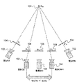
図2は、ステレオ3Dの左ビュー・キャプチャ及び右ビュー・キャプチャを表す。ステレオ3Dでは、TV受像機は、左ビュー及び右ビューに対応する2個のビューを順次、表示し、人間の視覚系はシーンの空間ビジョンを再構成する。TV受像機は更に、表示サイズ、及び/又は部屋における視聴者の位置などのユーザ環境に適合された仮想ビューを合成することができる。よって、通常の場合には、ステレオ3Dは、シーン205の右ビュー204を捕捉する実カメラ203及び左ビュー202を捕捉する実カメラ201を含む。3D空間における点Pは、左ビューにおける画素P1及び右ビューにおける画素P2によって表される。通常のステレオ3Dキャプチャでは、カメラ201及び203は、水平軸206上でアラインされ、垂直軸207に沿って誘導される。一変形では、仮想カメラ209によって捕捉されたビューに対応する中間ビュー208は、左ビュー202若しくは右ビュー204、又は両方を使用してTV受像機によって合成される。次いで、中間ビュー208は、左ビュー又は右ビューとしてユーザに向けてレンダリングされる。この中間ビューは、ユーザの視覚的快適性を向上させる。この処理は、ベースライン補正と呼ばれる。
FIG. 2 represents stereo 3D left and right view capture. In stereo 3D, the TV receiver sequentially displays two views corresponding to the left view and the right view, and the human visual system reconstructs the spatial vision of the scene. The TV receiver can further synthesize a virtual view adapted to the user environment, such as the display size and / or the position of the viewer in the room. Thus, in the normal case, the stereo 3D includes a
仮想ビューの合成は、水平変位d1だけ、左ビューの各画素P1を移動させることによって得られ、この変位は、実カメラの固有のパラメータ、及びビュー内の点Pの深度に依存する。この原理は、右ビューにおける画素P2の変位にも該当する。画素が、シーン内の同じ点Pに対応しているからである。 Synthesis of virtual view, only the horizontal displacement d 1, obtained by moving each pixel P 1 of the left view, this displacement, specific parameters of the real camera, and on the P depth points in the view. This principle also applies to the displacement of the pixel P2 in the right view. This is because a pixel corresponds to the same point P in the scene.
図3は、同じシーンの別々の2つのビューにおける画素の変位を表す。左ビュー301及び右ビュー302は、3つのオブジェクト(すなわち、前景における人物、背景における家、及びそれらの間の木)を含む同じシーンの2つの表現を表す。木の点は画素P1によって表される。左ビュー301における画素P1の座標303、及び右ビュー302における同じ画素P1の座標304は異なる。こうしたバリエーションは、コヒーレントに別々のビューに透かしを入れるという課題をもたらす。透かしサンプルを担持する画素の座標が、ビュー間で異なるからである。実カメラ及び仮想カメラがアラインされている場合(ステレオ3Dにおけるベースライン補正などの大半のアプリケーションの場合、該当する)では、変位d1は、水平軸305のみに沿っている。一般に、(i)カメラの光軸が平行であり、(ii)光軸が、カメラ全ての光心を通って進む線に対して直交であり、(iii)カメラ全てが同じ焦点距離を共有し、(iv)カメラ間で回転が存在しない場合、点の変位は、カメラの光心を通って進む軸に平行の軸に沿って生じる。よって、透かし信号が前述の軸に沿って不変である場合、何れの実ビュー上でも、合成された中間ビュー上でも同じになる。前述の軸は、本発明の不変領域を定義する。
FIG. 3 represents pixel displacements in two different views of the same scene.
実際には、オクルージョンのために課題はやや複雑になる。一部のオブジェクト部分は一部のビュー上のみに現れ、他の部分上には、現れない。しかし、オクルージョンは、ビューの非常に小さい領域のみを包含し、本願の目的では無視し得る。 In practice, the problem is somewhat complicated due to occlusion. Some object parts appear only on some views and not on other parts. However, occlusion encompasses only a very small area of the view and can be ignored for purposes of this application.
図4は、透かしが空間領域に埋め込まれた、特定の実施例による透かし埋込みの方法を表す。マルチ・ビュー・ビデオはN個のビューを含み、以下の工程は、N個のビューのうちのビュー毎に並列に、又は順次、反復される。 FIG. 4 represents a watermark embedding method according to a particular embodiment in which the watermark is embedded in the spatial domain. The multi-view video includes N views, and the following steps are repeated in parallel or sequentially for each of the N views.
実ビュー1は、RGB又はYCrCbの約束ごとを使用して画素値により、空間領域において表される。好ましい実施例では、輝度値が、空間領域におけるビューIの画素値として使用される。
第1の工程E1では、ビューIの空間表現は、不変ベクトルiを生成するために投影関数を使用して不変空間に投影する。すなわち、実ビューの組、又は何れかの実ビューから生成される合成ビューは何れも、この投影関数を使用して同じ不変ベクトルに投影される。前述の実施例では、投影関数は例えば、不変領域を構成するビューの線に沿ったサンプル値の合計である。カメラが水平軸上でアラインされる精緻化では、投影関数は水平線に沿った輝度値の合計である。 In the first step E1, the spatial representation of the view I is projected onto the invariant space using a projection function to generate the invariant vector i. That is, any set of real views or a composite view generated from any real view is projected onto the same invariant vector using this projection function. In the example described above, the projection function is, for example, the sum of the sample values along the view lines that make up the invariant region. In refinements where the camera is aligned on the horizontal axis, the projection function is the sum of the luminance values along the horizontal line.
次の工程E2では、不変ベクトルiは、次いで、不変の透かしを入れたベクトルiwを生成するために、スペクトル拡散透かし入れ又は量子化ベースの透かし入れなどの何れかの従来技術の透かし埋込みアルゴリズムを使用して透かしが入れられる。 In the next step E2, invariant vector i is then to produce a vector i w watermarked unchanged, any watermark embedding algorithm of the prior art, such as spread spectrum watermarking or quantization based watermarking Is used to watermark.
その後、工程E3では、不変透かしベクトルw=iw−1が計算される。 Thereafter, in step E3, an invariant watermark vector w = i w −1 is calculated.
工程E4では、不変1D透かしベクトルwが次いで、2D透かし信号Wを得るために分布関数を使用して空間表現領域にもう一度マッピングされる。よって、透かし信号WはビューIと同じ寸法を有する。一実施例では、分布関数は、正規化因子で、投影の不変軸に沿ってベクトルwを数回、複製することを含む。盲目的検出を可能にするために、透かし信号は、水平軸に沿って非ナルDC成分を有するものとする。空間領域では、寸法h(ビューの高さ)の擬似ランダム・ベクトルvが、例えば、ガウスの法則に従って生成される。バンドパス・フィルタfは、バンドパス擬似ランダム透かしベクトルvHを得るためにベクトルvに適用される。次いで、透かしベクトルをI(ビュー幅)回、複製して、h×I 2D透かし信号Wを得る。 In step E4, the invariant 1D watermark vector w is then mapped once again into the spatial representation region using a distribution function to obtain a 2D watermark signal W. Thus, the watermark signal W has the same dimensions as the view I. In one embodiment, the distribution function includes replicating the vector w several times along the projection invariant axis with a normalization factor. To enable blind detection, the watermark signal shall have a non-null DC component along the horizontal axis. In the spatial domain, a pseudo-random vector v of dimension h (view height) is generated, for example, according to Gauss's law. Bandpass filter f is applied to the vector v in order to obtain a band-pass pseudorandom watermark vector v H. The watermark vector is then duplicated I (view width) times to obtain an h × I 2D watermark signal W.
次いで、工程E5では、ビューI及び透かし信号Wを、特定の融合アルゴリズムを使用してマージして、透かしを入れた出力ビューIwを生成する。好ましい実施例では、融合関数は単純な加算のみを表す。 Then, in step E5, view I and watermark signal W are merged using a specific fusion algorithm to produce a watermarked output view Iw. In the preferred embodiment, the fusion function represents only a simple addition.
Iw=I+bW
ここで、b∈{−1,1}は、挿入する対象の透かしビットである。最も一般的な場合には、透かし信号Wは実ビューIにも依存し得る。よって、一変形では、融合関数は更に、一部の知覚的制約に対処するためのマスキング関数を更に含む。これをするために、透かし信号Wは、加算前に可視性マスクM(I)によって変調し得る。
I w = I + bW
Here, bε {−1,1} is a watermark bit to be inserted. In the most general case, the watermark signal W may also depend on the real view I. Thus, in one variation, the fusion function further includes a masking function to address some perceptual constraints. To do this, the watermark signal W can be modulated by a visibility mask M (I) before addition.
Iw=I+bW・M(I)
ここで、演算子・は、2つのマトリクスの項毎の乗算を表す。前述の可視性マスクは、画像の局所周波数構成に依存し(周波数マスキング)、かつ/又は画像の局所画素強度に依存し得る(輝度マスキング)。マスキング関数Mの種々の実施例はしたがって、知覚的シェーピングがないことに対応するM(I)=1であり、M(I)=Iは、輝度マスキングに対応し、乗算埋込みをもたらし、M(I)=S(I)であり、ここで、S(I)は、周波数マスキングに対応する、画素位置それぞれを中心とした局所分散を含むマトリクスである。最後に、融合関数は、避けられない丸め演算及びクリッピング演算による透かしエネルギ損失を最小にするために調整し得る。
I w = I + bW · M (I)
Here, the operator • represents multiplication for each term of two matrices. Such visibility masks may depend on the local frequency configuration of the image (frequency masking) and / or may depend on the local pixel intensity of the image (luminance masking). Various embodiments of the masking function M are therefore M (I) = 1 corresponding to the absence of perceptual shaping, where M (I) = I corresponds to luminance masking, resulting in multiplication embedding and M (I I) = S (I), where S (I) is a matrix containing local variances centered on each pixel location corresponding to frequency masking. Finally, the fusion function can be adjusted to minimize watermark energy loss due to unavoidable rounding and clipping operations.
工程E3乃至E5はしたがって、iwに投影する、透かしを入れたビューIwを回復するための方法を提案している。 Step E3 to E5 are thus projected to i w, we propose a method for recovering the view I w watermarked.
図5は、透かしが空間領域に埋め込まれる、別の特定の実施例による透かし埋込みの方法を図示する。空間領域やウェーブレット領域などの別々の表現領域に透かしが埋め込まれているということを透かし入れの分野における当業者は認識するであろう。よって、実ビューIが空間領域において画素で表される場合、実ビューIも、周波数領域において、ビューのウェーブレット変換によって表される。 FIG. 5 illustrates a method of watermark embedding according to another specific embodiment in which the watermark is embedded in the spatial domain. Those skilled in the art of watermarking will recognize that the watermark is embedded in separate representation areas such as the spatial domain and the wavelet domain. Therefore, when the real view I is represented by pixels in the spatial domain, the real view I is also represented by the wavelet transform of the view in the frequency domain.
第1の工程E10では、ビューIは、不変ベクトルiを生成するために投影関数を使用して不変空間に投影される。すなわち、実ビューの組、又は何れかの実ビューから生成される合成ビューは何れも、この投影関数を使用して同じ不変ベクトルに投影される。 In the first step E10, the view I is projected into the invariant space using a projection function to generate the invariant vector i. That is, any set of real views or a composite view generated from any real view is projected onto the same invariant vector using this projection function.
次いで、次の工程E11では、領域変換は、不変ベクトルrの適切な空間周波数表現を得るために1D不変ベクトルiに適用される。この実施例によれば、ウェーブレット変換は、例えば、ベクトルに適用される。変形実施例では、領域変換は、ビューの適切な空間周波数表現を得るために実ビューIに直接適用される。この直近の変形では、領域変換は、ビューの各列に適用される1D列ウェーブレット変換であり、投影関数は例えば、変換されたビューの線に沿った合計である。しかし、2D実ビューでなく、1D投影ビューに領域変換を適用することにより、効果的には、計算時間及び計算能力を削減する。 Then, in the next step E11, a domain transformation is applied to the 1D invariant vector i to obtain an appropriate spatial frequency representation of the invariant vector r. According to this embodiment, the wavelet transform is applied to a vector, for example. In a variant embodiment, the domain transformation is applied directly to the real view I to obtain an appropriate spatial frequency representation of the view. In this most recent variant, the region transform is a 1D column wavelet transform applied to each column of the view, and the projection function is, for example, the sum along the transformed view line. However, applying the domain transformation to the 1D projected view instead of the 2D actual view effectively reduces the computation time and computing power.
次の工程E12では、不変ベクトルrには、次いで、不変の透かしを入れたベクトルrwを生成するために、スペクトル拡散透かし入れ又は量子化ベースの透かし入れなどの何れかの従来技術の透かし埋込みアルゴリズムを使用して透かしが入れられる。ウェーブレット領域では、長さh(画像の高さ)の1D擬似ランダム・ベクトルvが生成される。非可視性及びロバスト性の目的で、vの各サンプルの強度は、属するサブバンドに応じて調節し得る。例えば、低周波構成部分の強度は、透かしの可視性を妨げるために、低い(又はナルである)ことがあり得る。逆に、バンドパス構成部分の強度は、より高いことがあり得る。好適な可視性・ロバスト性のトレードオフをもたらすからである。 In the next step E12, the invariant vector r, then, in order to generate a vector r w watermarked unchanged, Watermarking any conventional techniques such as spread spectrum watermarking or quantization based watermarking An algorithm is used to watermark. In the wavelet region, a 1D pseudo-random vector v having a length h (image height) is generated. For invisibility and robustness purposes, the intensity of each sample of v can be adjusted depending on the subband to which it belongs. For example, the strength of the low frequency component can be low (or null) to prevent watermark visibility. Conversely, the strength of the bandpass component can be higher. This is because it provides a favorable visibility / robustness trade-off.
その後、工程E13では、不変透かしベクトルw=rw−rが計算される。 Thereafter, in step E13, an invariant watermark vector w = r w −r is calculated.
次いで、工程E14では、逆領域変換が、空間領域における不変透かしベクトルvを得るために適用される。この実施例によれば、逆ウェーブレット変換が例えば、ベクトルに対して適用される。領域変換が、投影されたビューでなく、ビューに対して適用される実施例では、逆変換の工程が、分布の工程の後に適用される。よって、透かしの空間周波数表現は、空間領域において透かしWを得るために変換される。この直近の変形では、逆変換は例えば、透かしの空間周波数表現の各列に適用された1D列逆ウェーブレット変換である。 Then, in step E14, an inverse domain transform is applied to obtain an invariant watermark vector v in the spatial domain. According to this embodiment, an inverse wavelet transform is applied to the vector, for example. In embodiments where region transformations are applied to views rather than projected views, the inverse transformation step is applied after the distribution step. Thus, the spatial frequency representation of the watermark is transformed to obtain the watermark W in the spatial domain. In this latest variant, the inverse transform is, for example, a 1D sequence inverse wavelet transform applied to each column of the spatial frequency representation of the watermark.
工程E15では、1D透かしベクトルwが次いで、2次元透かし信号Wを得るために分布関数を使用して空間表現領域にもう一度マッピングされる。よって、透かし信号WはビューIの空間表現と同じ寸法を有する。一実施例では、分布関数は、正規化因子で、投影の不変軸に沿ってベクトルwを数回、複製することを含む。 In step E15, the 1D watermark vector w is then mapped again into the spatial representation region using a distribution function to obtain a two-dimensional watermark signal W. Thus, the watermark signal W has the same dimensions as the spatial representation of view I. In one embodiment, the distribution function includes replicating the vector w several times along the projection invariant axis with a normalization factor.
次いで、工程E16では、ビューI及び透かし信号Wを、特定の融合アルゴリズムを使用してマージして、透かしを入れた出力ビューIwを生成する。好ましい実施例では、融合関数は単純な加算のみを表す。 Next, in step E16, the view I and a watermark signal W, and merged using the particular fusion algorithm to produce an output view I w watermarked. In the preferred embodiment, the fusion function represents only a simple addition.
Iw=I+bW
ここで、b∈{−1,1}は、挿入する対象の透かしビットである。空間領域に関する実施例については、可視性マスクM(I)が、加算前に適用され、透かしの非可視性が向上する。
I w = I + bW
Here, bε {−1,1} is a watermark bit to be inserted. For the spatial domain example, a visibility mask M (I) is applied before the addition to improve watermark invisibility.
Iw=I+bW・M(I)
工程E13乃至E16はしたがって、iwに投影する、透かしを入れたビューIwを回復するための方法を提案している。
I w = I + bW · M (I)
Step E13 to E16 are thus projected to i w, we propose a method for recovering the view I w watermarked.
別の変形実施例によれば、不変透かしベクトル(w)は、中間合成ビューに対し、かつ、複数のビューに対して不変の領域において直接生成される。不変透かしベクトルは、例えば、擬似ランダム・サンプルである。よって、結果として生じる不変ベクトルに、透かしアルゴリズムを適用する工程、及びビューを投影する工程はバイパスされる。 According to another variant embodiment, the invariant watermark vector (w) is generated directly in the invariant region for the intermediate composite view and for the multiple views. The invariant watermark vector is, for example, a pseudo-random sample. Thus, applying the watermark algorithm and projecting the view to the resulting invariant vector is bypassed.
図6は、特定の実施例による透かし検出の方法を図示する。 FIG. 6 illustrates a method of watermark detection according to a particular embodiment.
レンダリングされたビューI’wは、空間領域において画素値で表される。第1の工程D1では、ビューI’wは、不変ベクトルi’wを生成するために投影関数を使用して不変空間に投影される。変形では、方法は更に、領域変換を含む。変換関数及び投影関数は、埋込み方法及び検出方法において必然的に同一である。したがって、一変形では、工程D1より前に、領域変換を、レンダリングされたビューI’wに適用して、ビューの適切な空間周波数表現を取得し、次いで投影する。別の変形では、工程D1に続いて、領域変換が、不変ベクトルi’wの適切な空間周波数表現を得るために投影ビューに適用される。 The rendered view I ′ w is represented by pixel values in the spatial domain. In the first step D1, the view I ′ w is projected onto the invariant space using a projection function to generate an invariant vector i ′ w . In a variant, the method further includes region transformation. The transformation function and the projection function are necessarily the same in the embedding method and the detection method. Thus, in one variation, prior to step D1, a domain transformation is applied to the rendered view I ′ w to obtain an appropriate spatial frequency representation of the view and then project it. In another variation, following the step D1, domain transform is applied to projection views in order to obtain an appropriate spatial frequency representation of the invariant vector i 'w.
第2の工程D2では、既知の透かし検出方法が、一次元ベクトルi’wに適用される。空間表現実施例によれば、レンダリングされたビューI’wの各線の輝度値を平均化して寸法h(ビューの高さ)の平均ベクトルi’wを得る。バンドパス・フィルタfを平均ベクトルi’wに適用し、相関スコアを、透かしを入れたバンドパス・ベクトルf(i’w)について計算して透かしの存在を評価する。復号化された透かしビットbは相関符号に依存する。 In the second step D2, known watermark detection method is applied to a one-dimensional vector i 'w. According to the spatial representation embodiment, the luminance values of each line of the rendered view I ′ w are averaged to obtain an average vector i ′ w of dimension h (view height). A bandpass filter f is applied to the average vector i ′ w and a correlation score is calculated for the watermarked bandpass vector f (i ′ w ) to evaluate the presence of the watermark. The decoded watermark bit b depends on the correlation code.
当然、本発明は、上述の実施例に限定されない。 Of course, the present invention is not limited to the embodiments described above.
特に、本発明は、カメラ位置及び向きに応じて何れかの不変領域(水平線、平行線、又はより複雑な投影)と互換である。更に、特定の特徴によれば、透かし埋込みは、空間領域又は周波数領域におけるビューの何れかの表現において処理される。最後に、特定の特徴によれば、空間領域においてビューを構成する画素は、その輝度値で表され、更に、クロミナンス値又は、RGB値の何れかでも表される。 In particular, the present invention is compatible with any invariant region (horizontal line, parallel line, or more complex projection) depending on the camera position and orientation. Furthermore, according to a particular feature, watermark embedding is processed in the representation of views in either the spatial domain or the frequency domain. Finally, according to a particular feature, the pixels making up the view in the spatial domain are represented by their luminance values, and also by either chrominance values or RGB values.
101 シーン
102 カメラ
103 仮想カメラ
104 ビュー
105 仮想ビュー
201 実カメラ
202 ビュー
203 実カメラ
204 ビュー
205 シーン
206 水平軸
207 垂直軸
208 中間ビュー
209 仮想カメラ
301 ビュー
302 ビュー
303 座標
304 座標
305 水平軸
101
Claims (13)
i)前記カメラの光軸が平行であり、
ii)光軸が、カメラ全ての光心を通って進む線に対して直交であり、
iii)カメラは全て、同じ焦点距離を共有し、
iV)前記カメラ間に回転が存在していない
という条件で、前記ビュー(I)を、中間合成ビューに対し、かつ、前記複数のビューに対して不変の領域に投影し、不変ベクトル(i)をもたらす工程(E1)であって、前記不変の領域は、前記カメラの光心を通って進む線に平行の何れかの線に沿って複数のサンプル値を含み、平行線はビュー不変寸法と呼ばれる工程と、
前記不変ベクトル(i)に透かし入れアルゴリズムを適用し、透かしを入れた不変ベクトル(iw)をもたらす工程(E2)と、
前記不変ベクトル(i)を、前記透かしを入れた不変ベクトル(iw)から減算し、前記不変透かしベクトル(w)を得る工程(E3)と、
前記ビュー不変寸法にわたって前記不変透かしベクトル(w)を分布させ、透かし信号(W)をもたらす工程(E4)と、
前記透かし信号(W)を前記ビュー(I)とマージして、透かしを入れたビュー(Iw)をもたらす工程(E5)とを含む方法。 A method of embedding a watermark in a multi-view video having multiple views captured by multiple cameras, for each view,
i) the optical axis of the camera is parallel;
ii) the optical axis is orthogonal to the line traveling through the optical center of all cameras,
iii) All cameras share the same focal length,
iV) Projecting the view (I) onto an intermediate composite view and to an invariant region with respect to the plurality of views on the condition that no rotation exists between the cameras, and an invariant vector (i) Wherein the invariant region includes a plurality of sample values along any line parallel to a line traveling through the optical center of the camera, wherein the parallel line has a view invariant dimension and A process called
Applying a watermarking algorithm to the invariant vector (i) to yield a watermarked invariant vector (i w );
Subtracting the invariant vector (i) from the invariant vector (i w ) with the watermark to obtain the invariant watermark vector (w) (E3);
Distributing the invariant watermark vector (w) over the view invariant dimensions to yield a watermark signal (W) (E4);
Merging the watermark signal (W) with the view (I) to yield a watermarked view (I w ) (E5).
前記不変透かしベクトルの空間周波数表現を不変透かしベクトル(w)にもう一度変換する第1の工程(E14)を含む方法。 4. The method according to claim 3, wherein the step (E15) of distributing the invariant vector watermark (w) further comprises:
A method comprising a first step (E14) of once again converting the spatial frequency representation of the invariant watermark vector into an invariant watermark vector (w).
透かし(W)の空間表現に透かしの空間周波数表現をもう一度変換する最後の工程を含む方法。 6. The method of claim 5, wherein the step (E4) of distributing the invariant watermark vector (w) further comprises:
A method comprising the final step of once again converting the spatial frequency representation of the watermark into a spatial representation of the watermark (W).
i)前記カメラの光軸が平行であり、
ii)光軸が、カメラ全ての光心を通って進む線に対して直交であり、
iii)カメラは全て、同じ焦点距離を共有し、
iV)前記カメラ間に回転が存在していない
という条件で、中間合成ビューに対し、かつ、前記複数のビューに対して不変の領域において不変透かしベクトル(w)を生成する工程であって、前記不変の領域は、前記カメラの光心を通って進む線に平行の何れかの線に沿って複数のサンプル値を含み、前記平行線はビュー不変寸法と呼ばれる工程と、
前記ビュー不変寸法にわたって前記不変透かしベクトル(w)を分布させ、透かし信号(W)をもたらす工程(E4)と、
前記透かし信号(W)をビュー(I)とマージして、透かしを入れたビュー(Iw)をもたらす工程(E5)とを含む方法。 A method of embedding a watermark in a multi-view video having multiple views captured by multiple cameras, for each view,
i) the optical axis of the camera is parallel;
ii) the optical axis is orthogonal to the line traveling through the optical center of all cameras,
iii) All cameras share the same focal length,
iV) generating an invariant watermark vector (w) for an intermediate composite view and in an invariant region for the plurality of views on the condition that there is no rotation between the cameras, The invariant region includes a plurality of sample values along any line parallel to a line traveling through the optical center of the camera, the parallel lines being called view invariant dimensions;
Distributing the invariant watermark vector (w) over the view invariant dimensions to yield a watermark signal (W) (E4);
Merging said watermark signal (W) with view (I) to yield a watermarked view (I w ) (E5).
前記レンダリングされたビューについて、
i)前記カメラの光軸が平行であり、
ii)光軸が、カメラ全ての光心を通って進む線に対して直交であり、
iii)カメラは全て、同じ焦点距離を共有し、
iv)前記カメラ間に回転が存在していない
という条件で、中間合成ビューに対し、かつ、前記複数のビューに対して不変の領域に対して、前記レンダリングされたビューを投影する工程(D1)であって、前記不変の領域は、前記カメラの光心を通って進む線に平行の何れかの線に沿って複数のサンプル値を含み、前記平行線はビュー不変寸法と呼ばれる工程と、
透かしの存在を評価するために、透かし検出アルゴリズムを不変のレンダリングされたベクトル(i’w)に適用する工程(D2)と
を含む方法。 A method for detecting a watermark in a multi-view video having a rendered view selected or synthesized from multiple views captured by multiple cameras, comprising:
For the rendered view:
i) the optical axis of the camera is parallel;
ii) the optical axis is orthogonal to the line traveling through the optical center of all cameras,
iii) All cameras share the same focal length,
iv) projecting the rendered view to an intermediate composite view and to an area that is invariant to the plurality of views, provided that there is no rotation between the cameras (D1) The invariant region includes a plurality of sample values along any line parallel to a line traveling through the camera optical center, the parallel lines being referred to as view invariant dimensions;
Applying a watermark detection algorithm to an invariant rendered vector (i ′ w ) to evaluate the presence of the watermark (D2).
Applications Claiming Priority (2)
| Application Number | Priority Date | Filing Date | Title |
|---|---|---|---|
| EP10305940A EP2426635A1 (en) | 2010-09-01 | 2010-09-01 | Method for watermarking free view video with blind watermark detection |
| EP10305940.8 | 2010-09-01 |
Publications (2)
| Publication Number | Publication Date |
|---|---|
| JP2012054933A true JP2012054933A (en) | 2012-03-15 |
| JP2012054933A5 JP2012054933A5 (en) | 2014-10-09 |
Family
ID=43086319
Family Applications (1)
| Application Number | Title | Priority Date | Filing Date |
|---|---|---|---|
| JP2011188516A Ceased JP2012054933A (en) | 2010-09-01 | 2011-08-31 | Method for watermarking free view video with blind watermark detection |
Country Status (5)
| Country | Link |
|---|---|
| US (1) | US8477991B2 (en) |
| EP (2) | EP2426635A1 (en) |
| JP (1) | JP2012054933A (en) |
| KR (1) | KR20120022675A (en) |
| CN (1) | CN102387421A (en) |
Families Citing this family (10)
| Publication number | Priority date | Publication date | Assignee | Title |
|---|---|---|---|---|
| WO2013029696A1 (en) * | 2011-08-30 | 2013-03-07 | Telefonaktiebolaget L M Ericsson (Publ) | Receiver-side adjustment of stereoscopic images |
| KR101321896B1 (en) * | 2012-05-23 | 2013-10-28 | 광운대학교 산학협력단 | A watermarking method based on occlusion for copyright protection of stereoscopic image |
| RU2012138174A (en) * | 2012-09-06 | 2014-03-27 | Сисвел Текнолоджи С.Р.Л. | 3DZ TILE FORMAT DIGITAL STEREOSCOPIC VIDEO FLOW FORMAT METHOD |
| CN103093127B (en) * | 2013-01-21 | 2015-07-15 | 深圳大学 | Method and system of dynamic copyright protection based on sudoku and multiple digital watermarks |
| CN103198448B (en) * | 2013-04-11 | 2016-08-03 | 江苏大学 | Threedimensional model digital watermark embedding based on vertex curvature and blind checking method |
| EP2821956A1 (en) | 2013-07-05 | 2015-01-07 | Thomson Licensing | Method for detecting a watermark in a video |
| IN2013CH05744A (en) | 2013-12-12 | 2015-06-19 | Infosys Ltd | |
| EP3115963A1 (en) | 2015-07-10 | 2017-01-11 | Thomson Licensing | Method for generating a pair of disparity-coherent watermarks |
| CN109064377B (en) * | 2018-07-24 | 2023-03-31 | 中国传媒大学 | Stereo image watermark embedding system, stereo image watermark extracting system, stereo image watermark embedding method and stereo image watermark extracting method |
| US11303777B2 (en) * | 2020-08-06 | 2022-04-12 | Huawei Technologies Co., Ltd. | System, method and apparatus for digital watermarking |
Citations (1)
| Publication number | Priority date | Publication date | Assignee | Title |
|---|---|---|---|---|
| WO2008041061A1 (en) * | 2006-10-05 | 2008-04-10 | Vestel Elektronik Sanayi Ve Ticaret A.S. | Watermark detection method for broadcasting |
Family Cites Families (6)
| Publication number | Priority date | Publication date | Assignee | Title |
|---|---|---|---|---|
| US7502759B2 (en) * | 1999-08-30 | 2009-03-10 | Digimarc Corporation | Digital watermarking methods and related toy and game applications |
| AU2003216669A1 (en) * | 2002-05-10 | 2003-11-11 | Koninklijke Philips Electronics N.V. | Watermark embedding and retrieval |
| JP2004248054A (en) * | 2003-02-14 | 2004-09-02 | Matsushita Electric Ind Co Ltd | Method for enhancing blind detection of non-shift watermark with filtering and/or downscaled data as object |
| JP2005192001A (en) * | 2003-12-26 | 2005-07-14 | Toshiba Corp | Electronic watermark embedding method and electronic watermark embedding device |
| CN101389009B (en) * | 2007-09-14 | 2010-12-15 | 华为技术有限公司 | Watermark information embedding, detection method and device |
| GB2473059A (en) * | 2009-08-28 | 2011-03-02 | Sony Corp | A method and apparatus for forming a composite image |
-
2010
- 2010-09-01 EP EP10305940A patent/EP2426635A1/en not_active Withdrawn
-
2011
- 2011-08-25 US US13/199,308 patent/US8477991B2/en not_active Expired - Fee Related
- 2011-08-31 EP EP11179468.1A patent/EP2426636B1/en not_active Not-in-force
- 2011-08-31 KR KR1020110088039A patent/KR20120022675A/en not_active Application Discontinuation
- 2011-08-31 JP JP2011188516A patent/JP2012054933A/en not_active Ceased
- 2011-09-01 CN CN2011102566138A patent/CN102387421A/en active Pending
Patent Citations (1)
| Publication number | Priority date | Publication date | Assignee | Title |
|---|---|---|---|---|
| WO2008041061A1 (en) * | 2006-10-05 | 2008-04-10 | Vestel Elektronik Sanayi Ve Ticaret A.S. | Watermark detection method for broadcasting |
Non-Patent Citations (3)
| Title |
|---|
| JPN6016006152; Ning Zhu, et.al.: '"A Novel Digital Watermarking Method for New Viewpoint Video Based on Depth Map"' Eighth Int. Conf. on Intelligent Systems Design and Applications 2008 (ISDA '08) Vol.2, 20081128, p.3-7 * |
| JPN6016006153; Halici, E., et.al.: '"WATERMARKING FOR DEPTH-IMAGE-BASED RENDERING"' Proc. of 16th IEEE Int. Conf. on Image Processing (ICIP) 2009 , 20091110, p.4217-4220 * |
| JPN6016006154; Apostolidis, E.E., et.al.: '"FREE-VIEW TV WATERMARK SELECTION BASED ON THE DISTRIBUTION CHARACTERISTICS"' Proc. of 3DTV Conference: The True Vision - Capture, Transmission and Display of 3D Video 2009 , 20090506, p.1-4 * |
Also Published As
| Publication number | Publication date |
|---|---|
| EP2426636B1 (en) | 2018-06-13 |
| EP2426636A1 (en) | 2012-03-07 |
| US20120063634A1 (en) | 2012-03-15 |
| US8477991B2 (en) | 2013-07-02 |
| CN102387421A (en) | 2012-03-21 |
| KR20120022675A (en) | 2012-03-12 |
| EP2426635A1 (en) | 2012-03-07 |
Similar Documents
| Publication | Publication Date | Title |
|---|---|---|
| JP2012054933A (en) | Method for watermarking free view video with blind watermark detection | |
| US9202257B2 (en) | System for determining an illegitimate three dimensional video and methods thereof | |
| JP4828506B2 (en) | Virtual viewpoint image generation device, program, and recording medium | |
| Franco-Contreras et al. | Virtual view invariant domain for 3D video blind watermarking | |
| Chen et al. | Robust contourlet-based blind watermarking for depth-image-based rendering 3D images | |
| Liu et al. | Novel robust zero-watermarking scheme for digital rights management of 3D videos | |
| US9384521B2 (en) | Method and device for assessing the presence of a watermark in a video | |
| Solh et al. | Hierarchical hole-filling (HHF): Depth image based rendering without depth map filtering for 3D-TV | |
| Pei et al. | Auxiliary metadata delivery in view synthesis using depth no synthesis error model | |
| Al-Haj et al. | Transform-based watermarking of 3D depth-image-based-rendering images | |
| Liu et al. | A robust and synthesized-unseen watermarking for the DRM of DIBR-based 3D video | |
| Luo et al. | A robust digital watermarking method for depth-image-based rendering 3D video | |
| Nam et al. | NSCT-based robust and perceptual watermarking for DIBR 3D images | |
| Salih et al. | Imperceptible 3d video watermarking technique based on scene change detection | |
| KR20150104305A (en) | A watermarking method for 3D stereoscopic image based on depth and texture images | |
| Dhaou et al. | A review on anaglyph 3D image and video watermarking | |
| Hwang et al. | Real-time stereo image watermarking using discrete cosine transform and adaptive disparity maps | |
| Jaipuria | Watermarking for Depth Map Based 3D images using wavelet transform | |
| Chen et al. | A robust blind watermarking algorithm for depth-image-based rendering 3D images | |
| Dhaou et al. | An efficient anaglyph 3d video watermarking approach based on hybrid insertion | |
| Lin et al. | A novel blind watermarking scheme for depth-image-based rendering 3D images | |
| Muñoz-Ramírez et al. | A color image watermarking framework for copyright protection of stereo images based on binocular just noticeable difference and LU decomposition | |
| Al-Boeridi et al. | Three-Dimensional Video Watermarking–A Review and Open Challenges | |
| Salman et al. | Study Analysis to New Trend for 3D Video Watermark | |
| KR100779113B1 (en) | Method and system for stereo image watermarking using adaptive disparity estimation algorithm |
Legal Events
| Date | Code | Title | Description |
|---|---|---|---|
| A521 | Request for written amendment filed |
Free format text: JAPANESE INTERMEDIATE CODE: A523 Effective date: 20140822 |
|
| A621 | Written request for application examination |
Free format text: JAPANESE INTERMEDIATE CODE: A621 Effective date: 20140822 |
|
| A977 | Report on retrieval |
Free format text: JAPANESE INTERMEDIATE CODE: A971007 Effective date: 20150930 |
|
| A131 | Notification of reasons for refusal |
Free format text: JAPANESE INTERMEDIATE CODE: A131 Effective date: 20151020 |
|
| A521 | Request for written amendment filed |
Free format text: JAPANESE INTERMEDIATE CODE: A523 Effective date: 20160119 |
|
| A01 | Written decision to grant a patent or to grant a registration (utility model) |
Free format text: JAPANESE INTERMEDIATE CODE: A01 Effective date: 20160223 |
|
| A045 | Written measure of dismissal of application [lapsed due to lack of payment] |
Free format text: JAPANESE INTERMEDIATE CODE: A045 Effective date: 20160628 |