JP2012023597A - Image processing device and image processing method - Google Patents
Image processing device and image processing method Download PDFInfo
- Publication number
- JP2012023597A JP2012023597A JP2010160457A JP2010160457A JP2012023597A JP 2012023597 A JP2012023597 A JP 2012023597A JP 2010160457 A JP2010160457 A JP 2010160457A JP 2010160457 A JP2010160457 A JP 2010160457A JP 2012023597 A JP2012023597 A JP 2012023597A
- Authority
- JP
- Japan
- Prior art keywords
- motion vector
- unit
- block
- corner
- boundary
- Prior art date
- Legal status (The legal status is an assumption and is not a legal conclusion. Google has not performed a legal analysis and makes no representation as to the accuracy of the status listed.)
- Withdrawn
Links
Images
Classifications
-
- H—ELECTRICITY
- H04—ELECTRIC COMMUNICATION TECHNIQUE
- H04N—PICTORIAL COMMUNICATION, e.g. TELEVISION
- H04N19/00—Methods or arrangements for coding, decoding, compressing or decompressing digital video signals
- H04N19/10—Methods or arrangements for coding, decoding, compressing or decompressing digital video signals using adaptive coding
- H04N19/102—Methods or arrangements for coding, decoding, compressing or decompressing digital video signals using adaptive coding characterised by the element, parameter or selection affected or controlled by the adaptive coding
- H04N19/119—Adaptive subdivision aspects, e.g. subdivision of a picture into rectangular or non-rectangular coding blocks
-
- H—ELECTRICITY
- H04—ELECTRIC COMMUNICATION TECHNIQUE
- H04N—PICTORIAL COMMUNICATION, e.g. TELEVISION
- H04N19/00—Methods or arrangements for coding, decoding, compressing or decompressing digital video signals
- H04N19/50—Methods or arrangements for coding, decoding, compressing or decompressing digital video signals using predictive coding
- H04N19/503—Methods or arrangements for coding, decoding, compressing or decompressing digital video signals using predictive coding involving temporal prediction
- H04N19/51—Motion estimation or motion compensation
- H04N19/513—Processing of motion vectors
- H04N19/517—Processing of motion vectors by encoding
- H04N19/52—Processing of motion vectors by encoding by predictive encoding
Landscapes
- Engineering & Computer Science (AREA)
- Multimedia (AREA)
- Signal Processing (AREA)
- Compression Or Coding Systems Of Tv Signals (AREA)
Abstract
Description
本発明は、画像処理装置及び画像処理方法に関する。 The present invention relates to an image processing apparatus and an image processing method.
従来、デジタル画像を効率的に伝送し又は蓄積することを目的とし、画像に特有の冗長性を利用して、例えば離散コサイン変換などの直交変換と動き補償とにより画像の情報量を圧縮する圧縮技術が普及している。例えば、ITU−Tの策定したH.26x標準又はMPEG(Moving Picture Experts Group)の策定したMPEG−y標準などの標準技術に準拠した画像符号化装置及び画像復号化装置は、放送局による画像の蓄積及び配信、並びに一般ユーザによる画像の受信及び蓄積など、様々な場面で広く利用されている。 Conventionally, compression is intended to efficiently transmit or store digital images, and compresses the amount of information of an image using orthogonal transform such as discrete cosine transform and motion compensation, for example, using redundancy unique to the image. Technology is widespread. For example, H.264 developed by ITU-T. An image encoding device and an image decoding device compliant with standard technologies such as the 26x standard or the MPEG-y standard established by the Moving Picture Experts Group (MPEG) are used for storing and distributing images by broadcasting stations and for image data by general users. Widely used in various situations such as reception and storage.
MPEG2(ISO/IEC 13818-2)は、汎用画像符号化方式として定義されたMPEG−y標準の1つである。MPEG2は、飛び越し走査(インターレース)画像及び順次走査(ノン・インターレース)画像の双方を扱うことが可能であり、標準解像度のデジタル画像に加えて、高精細画像をも対象としている。MPEG2は、現在、プロフェッショナル用途及びコンシューマー用途を含む広範なアプリケーションに広く用いられている。MPEG2によれば、例えば、720×480画素を持つ標準解像度の飛び越し走査画像には4〜8Mbpsの符号量(ビットレート)、1920×1088画素を持つ高解像度の飛び越し走査画像には18〜22Mbpsの符号量を割り当てることで、高い圧縮率及び良好な画質を共に実現することができる。 MPEG2 (ISO / IEC 13818-2) is one of the MPEG-y standards defined as a general-purpose image coding system. MPEG2 can handle both interlaced (interlaced) images and progressively scanned (non-interlaced) images, and is intended for high-definition images in addition to standard resolution digital images. MPEG2 is currently widely used for a wide range of applications including professional and consumer applications. According to MPEG2, for example, a standard resolution interlaced scanning image having 720 × 480 pixels has a code amount (bit rate) of 4 to 8 Mbps, and a high resolution interlaced scanning image having 1920 × 1088 pixels has 18 to 22 Mbps. By assigning the code amount, both a high compression rate and good image quality can be realized.
MPEG2は、主として、放送の用途に適合する高画質符号化を目的としており、MPEG1よりも低い符号量(ビットレート)、即ちより高い圧縮率には対応するものではなかった。しかし、近年の携帯端末の普及により、高い圧縮率を可能とする符号化方式のニーズは高まっている。そこで、新たにMPEG4符号化方式の標準化が進められた。MPEG4符号化方式の一部である画像符号化方式に関しては、1998年12月に、その規格が国際標準(ISO/IEC 14496-2)として承認された。 MPEG2 is mainly intended for high image quality encoding suitable for broadcasting applications, and does not correspond to a lower code amount (bit rate) than MPEG1, that is, a higher compression rate. However, with the spread of portable terminals in recent years, the need for an encoding method that enables a high compression rate is increasing. Therefore, standardization of the MPEG4 encoding system was newly advanced. Regarding the image coding system which is a part of the MPEG4 coding system, the standard was approved as an international standard (ISO / IEC 14496-2) in December 1998.
H.26x標準(ITU-T Q6/16 VCEG)は、当初、テレビ電話又はテレビ会議などの通信の用途に適合する符号化を目的として策定された標準規格である。H.26x標準は、MPEG−y標準と比較して、符号化及び復号化により多くの演算量を要する一方、より高い圧縮率を実現できることが知られている。また、MPEG4の活動の一環としてのJoint Model of Enhanced-Compression Video Codingでは、H.26x標準をベースとしながら新たな機能をも取り入れることで、より高い圧縮率を実現可能な標準規格が策定された。この標準規格は、2003年3月に、H.264及びMPEG−4 Part10(Advanced Video Coding;AVC)という名称で国際標準となった。 H. The 26x standard (ITU-T Q6 / 16 VCEG) is a standard originally developed for the purpose of encoding suitable for communication applications such as videophone or videoconferencing. H. The 26x standard is known to be capable of realizing a higher compression ratio while requiring a larger amount of calculation for encoding and decoding than the MPEG-y standard. In the Joint Model of Enhanced-Compression Video Coding as part of MPEG4 activities, Based on the 26x standard, a standard that can achieve a higher compression ratio has been established by incorporating new functions. This standard was approved in March 2003 by H.264. H.264 and MPEG-4 Part 10 (Advanced Video Coding; AVC) have become international standards.
上述した画像符号化方式において重要な技術の1つは、動き補償である。一連の画像内で物体が大きく動いている場合、符号化対象画像と参照画像との差分も大きくなり、単純なフレーム間予測では高い圧縮率を得ることができない。しかし、物体の動きを認識し、動きが現れている領域の画素値をその動きに応じて補償することで、フレーム間予測による予測誤差が低減され、圧縮率が向上する。MPEG2において、動き補償は、フレーム動き補償モードの場合には16×16画素、フィールド動き補償モードの場合には第1フィールド及び第二フィールドのそれぞれに対して16×8画素を処理単位として行われる。また、H.264/AVCにおいては、16×16画素のサイズを有するマクロブロックを16×16画素、16×8画素、8×16画素及び8×8画素のいずれかのサイズの領域(partition)に分割し、各領域に個別に動きベクトルを設定することができる。また、8×8画素の領域をさらに8×8画素、8×4画素、4×8画素及び4×4画素のいずれかのサイズの領域に分割し、各領域に動きベクトルを設定することもできる。 One of the important techniques in the above-described image coding method is motion compensation. When an object moves greatly in a series of images, the difference between the encoding target image and the reference image also increases, and a high compression rate cannot be obtained by simple inter-frame prediction. However, by recognizing the motion of the object and compensating the pixel value of the region where the motion appears according to the motion, the prediction error due to inter-frame prediction is reduced, and the compression rate is improved. In MPEG2, motion compensation is performed in units of 16 × 16 pixels in the frame motion compensation mode, and in the field motion compensation mode, 16 × 8 pixels for each of the first field and the second field. . H. In H.264 / AVC, a macroblock having a size of 16 × 16 pixels is divided into a partition having a size of any one of 16 × 16 pixels, 16 × 8 pixels, 8 × 16 pixels, and 8 × 8 pixels, A motion vector can be set for each region individually. In addition, an 8 × 8 pixel region may be further divided into regions of any size of 8 × 8 pixels, 8 × 4 pixels, 4 × 8 pixels, and 4 × 4 pixels, and a motion vector may be set in each region. it can.
多くの場合、ある領域に設定される動きベクトルは、周囲のブロック又は領域に設定される動きベクトルと相関を有する。例えば、1つの動物体が一連の画像内で移動している場合、その動物体が映る範囲に属する複数の領域についての動きベクトルは、同じであるか、又は少なくとも類似するものとなる。また、ある領域に設定される動きベクトルは、時間方向の距離が近い参照画像内の対応する領域に設定される動きベクトルと相関を有する場合もある。そこで、MPEG4及びH.264/AVCなどの画像符号化方式は、このような動きの空間的相関又は時間的相関を利用して動きベクトルを予測し、予測された動きベクトルと実際の動きベクトルとの差分のみを符号化することにより、符号化される情報量の削減を図っている。また、下記非特許文献1は、動きの空間的相関及び時間的相関の双方を組み合わせて利用することを提案している。 In many cases, a motion vector set in a certain area has a correlation with a motion vector set in a surrounding block or area. For example, when one moving object is moving in a series of images, motion vectors for a plurality of regions belonging to a range in which the moving object is shown are the same or at least similar. In addition, a motion vector set in a certain region may have a correlation with a motion vector set in a corresponding region in a reference image having a short time direction distance. Therefore, MPEG4 and H.264 Image coding schemes such as H.264 / AVC predict the motion vector using such spatial correlation or temporal correlation of motion, and encode only the difference between the predicted motion vector and the actual motion vector. By doing so, the amount of information to be encoded is reduced. Non-Patent Document 1 below proposes to use both spatial correlation and temporal correlation of motion in combination.
動きベクトルの予測に際しては、符号化対象の領域と相関のある他のブロック又は領域を適切に選択することが求められる。その選択の基準となるのが、基準画素位置である。既存の画像符号化方式における動き補償の処理単位は、一般的に矩形の形状を有している。そのため、通常、矩形の左上若しくは右上又はその双方の画素位置が、動きベクトルの予測に際しての基準画素位置として選択され得る。 When predicting a motion vector, it is required to appropriately select another block or region having a correlation with the region to be encoded. The reference for the selection is the reference pixel position. The processing unit of motion compensation in the existing image encoding method generally has a rectangular shape. For this reason, usually, the pixel positions on the upper left and / or upper right of the rectangle or both can be selected as the reference pixel positions for motion vector prediction.
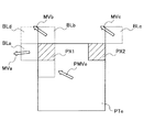
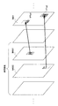
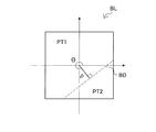
一方、画像内に現れる動物体の輪郭線は、水平及び垂直以外の傾きを有する場合が多い。そこで、そのような動物体と背景との間の動きの差異をより的確に動き補償に反映するために、下記非特許文献2は、図25に示したように、ブロックの中心点からの距離ρと傾き角θとにより定まる境界によって、ブロックを斜めに分割することを提案している。図25の例では、ブロックBLが、距離ρと傾き角θとにより定まる境界BDによって、第1の領域(partition)PT1及び第2の領域PT2に分割されている。このような手法を、「ジオメトリ動き分割(geometry motion partitioning)」という。また、ジオメトリ動き分割によって形成される各領域を、ジオメトリ領域(geometry partition)という。そして、ジオメトリ動き分割により形成されるジオメトリ領域ごとに、動き補償処理が行われ得る。 On the other hand, the contour line of the moving object appearing in the image often has an inclination other than horizontal and vertical. Therefore, in order to more accurately reflect the difference in motion between the moving object and the background in motion compensation, the following Non-Patent Document 2 describes the distance from the center point of the block as shown in FIG. It is proposed to divide a block diagonally by a boundary determined by ρ and an inclination angle θ. In the example of FIG. 25, the block BL is divided into a first region PT1 and a second region PT2 by a boundary BD determined by a distance ρ and an inclination angle θ. Such a method is called “geometry motion partitioning”. Each area formed by the geometry motion division is called a geometry partition. Then, motion compensation processing can be performed for each geometry region formed by geometry motion division.
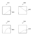
しかしながら、上述したジオメトリ動き分割のように、水平でも垂直でもない境界によってブロックを分割する場合、動き補償の処理単位である領域は、矩形以外の様々な形状をとり得る。例えば、図26に示すブロックBL1及びブロックBL2は、境界BD1及び境界BD2により、非矩形である多角形のジオメトリ領域にそれぞれ分割されている。また、将来の画像符号化方式において、図26に示すブロックBL3及びブロックBL4のように、曲線又は折れ線の境界(BD3、BD4)によりブロックを分割することも考えられる。これらの場合、例えば領域の左上又は右上などのように、一律的に基準画素位置を定義付けることは困難である。上記非特許文献2は、ジオメトリ動き分割における動きの空間的相関を利用した動きベクトルの予測についての一例を示しているが、非矩形領域において基準画素位置をどのように適応的に設定し得るかについては言及していない。 However, when a block is divided by a boundary that is neither horizontal nor vertical as in the above-described geometry motion division, the region that is a processing unit of motion compensation can take various shapes other than a rectangle. For example, the block BL1 and the block BL2 shown in FIG. 26 are each divided into polygonal geometric regions that are non-rectangular by the boundary BD1 and the boundary BD2. In a future image coding system, it is also conceivable to divide a block by a boundary of a curved line or a broken line (BD3, BD4) like the block BL3 and the block BL4 shown in FIG. In these cases, it is difficult to uniformly define the reference pixel position such as the upper left or upper right of the region. The above-mentioned Non-Patent Document 2 shows an example of motion vector prediction using spatial correlation of motion in geometry motion division. How can the reference pixel position be set adaptively in a non-rectangular region? Is not mentioned.
そこで、本発明は、矩形以外の様々な形状をとり得る分割方式でブロックが分割される場合に、適応的に基準画素位置を設定して動きベクトルを予測することのできる、画像処理装置及び画像処理方法を提供しようとするものである。 Therefore, the present invention provides an image processing apparatus and image that can adaptively set a reference pixel position and predict a motion vector when a block is divided by a division method that can take various shapes other than a rectangle. It is intended to provide a processing method.
本発明のある実施形態によれば、画像内に設定されるブロックを、傾きを有する境界を含む複数の候補から選択される境界により、複数の領域に分割する分割部と、上記境界の傾きに応じて変化する基準画素位置に対応するブロック又は領域に設定された動きベクトルに基づいて、上記分割部により分割されるブロック内の各領域内の画素値の予測に使用すべき動きベクトルを予測する動きベクトル予測部と、を備える画像処理装置が提供される。 According to an embodiment of the present invention, a block set in an image is divided into a plurality of regions by a boundary selected from a plurality of candidates including a boundary having an inclination, and the inclination of the boundary is set. Based on the motion vector set in the block or region corresponding to the reference pixel position that changes accordingly, the motion vector to be used for prediction of the pixel value in each region in the block divided by the dividing unit is predicted. An image processing apparatus including a motion vector prediction unit is provided.
上記画像処理装置は、典型的には、画像を符号化する画像符号化装置として実現され得る。ここで、「基準画素位置に対応するブロック又は領域」とは、例えば、参照画像内の基準画素と同じ位置の画素(即ち、コロケーテッド(co-located)な画素)が属するブロック又は領域を含み得る。また、「基準画素位置に対応するブロック又は領域」とは、例えば、同じ画像内で基準画素に隣接する画素が属するブロック又は領域を含み得る。 The image processing apparatus can typically be realized as an image encoding apparatus that encodes an image. Here, the “block or region corresponding to the reference pixel position” can include, for example, a block or region to which a pixel at the same position as the reference pixel in the reference image (that is, a co-located pixel) belongs. . The “block or region corresponding to the reference pixel position” may include, for example, a block or region to which a pixel adjacent to the reference pixel belongs in the same image.
また、上記境界の傾きに応じて、上記基準画素位置を各領域に設定する基準画素設定部、をさらに備えてもよい。 Further, a reference pixel setting unit that sets the reference pixel position in each region according to the inclination of the boundary may be further provided.
また、上記基準画素設定部は、上記境界がブロックの互いに対角に位置する第1のコーナー又は第2のコーナーに重なる場合には、当該ブロックの各領域の上記基準画素位置を、上記第1のコーナー及び上記第2のコーナーとは異なる第3のコーナー又は第4のコーナー上に設定してもよい。 In addition, when the boundary overlaps the first corner or the second corner located diagonally to each other in the block, the reference pixel setting unit determines the reference pixel position in each area of the block as the first pixel. It may be set on a third corner or a fourth corner different from the above corner and the second corner.
また、上記第1のコーナーは、ブロックの左上のコーナーであり、上記基準画素設定部は、上記境界が上記第1のコーナー及び上記第2のコーナーに重ならない場合には、上記第1のコーナーが属する第1の領域の上記基準画素位置を、上記第1のコーナー上に設定してもよい。 The first corner is an upper left corner of the block, and the reference pixel setting unit determines that the first corner is set when the boundary does not overlap the first corner and the second corner. The reference pixel position of the first region to which the image belongs may be set on the first corner.
また、上記基準画素設定部は、上記境界が上記第1のコーナー及び上記第2のコーナーに重ならず、上記第1のコーナーが属しない第2の領域に上記第2のコーナーが属する場合には、上記第2の領域の上記基準画素位置を、上記第2のコーナー上に設定してもよい。 The reference pixel setting unit may be configured such that the boundary does not overlap the first corner and the second corner, and the second corner belongs to a second region to which the first corner does not belong. The reference pixel position of the second region may be set on the second corner.
また、上記動きベクトル予測部は、上記基準画素位置に対応する参照画像内のブロック又は領域に設定された動きベクトルに基づく予測式を用いて、動きベクトルを予測してもよい。 The motion vector prediction unit may predict a motion vector using a prediction formula based on a motion vector set in a block or region in a reference image corresponding to the reference pixel position.
また、上記動きベクトル予測部は、上記基準画素位置に対応する参照画像内のブロック又は領域に設定された動きベクトルと、上記基準画素位置に隣接する他のブロック又は領域に設定された動きベクトルとに基づく予測式を用いて、動きベクトルを予測してもよい。 Further, the motion vector prediction unit includes a motion vector set in a block or region in a reference image corresponding to the reference pixel position, and a motion vector set in another block or region adjacent to the reference pixel position. The motion vector may be predicted using a prediction formula based on the above.
また、上記動きベクトル予測部は、上記基準画素位置に対応する参照画像内のブロック又は領域に設定された動きベクトルに基づく第1の予測式を用いて動きベクトルを予測し、上記基準画素位置に隣接する他のブロック又は領域に設定された動きベクトルに基づく第2の予測式を用いて動きベクトルを予測し、上記画像処理装置は、上記動きベクトル予測部による予測結果に基づいて、上記第1の予測式及び上記第2の予測式を含む複数の予測式の候補から最良の符号化効率を達成する予測式を選択する選択部、をさらに備えてもよい。 The motion vector prediction unit predicts a motion vector using a first prediction formula based on a motion vector set in a block or region in a reference image corresponding to the reference pixel position, and sets the reference pixel position. A motion vector is predicted using a second prediction formula based on a motion vector set in another adjacent block or region, and the image processing apparatus performs the first prediction based on a prediction result by the motion vector prediction unit. And a selection unit that selects a prediction formula that achieves the best coding efficiency from a plurality of prediction formula candidates including the prediction formula and the second prediction formula.
また、本発明の別の実施形態によれば、画像を処理するための画像処理方法において、画像内に設定されるブロックを、傾きを有する境界を含む複数の候補から選択される境界により、複数の領域に分割するステップと、上記境界の傾きに応じて変化する基準画素位置に対応するブロック又は領域に設定された動きベクトルに基づいて、分割されたブロック内の各領域内の画素値の予測に使用すべき動きベクトルを予測するステップと、を含む画像処理方法が提供される。 According to another embodiment of the present invention, in an image processing method for processing an image, a plurality of blocks set in an image are selected by a boundary selected from a plurality of candidates including a boundary having an inclination. And predicting pixel values in each area in the divided block based on the motion vector set in the block or area corresponding to the reference pixel position that changes in accordance with the inclination of the boundary. Predicting a motion vector to be used for the image processing method.
また、本発明の別の実施形態によれば、傾きを有する境界を含む複数の候補から選択される境界であって、画像の符号化の際に上記画像内のブロックを分割した上記境界の傾きを認識する境界認識部と、上記境界の傾きに応じて変化する基準画素位置に対応するブロック又は領域に設定された動きベクトルに基づいて、上記境界により分割されたブロック内の各領域内の画素値の予測に使用すべき動きベクトルを設定する動きベクトル設定部と、を備える画像処理装置が提供される。 According to another embodiment of the present invention, a boundary selected from a plurality of candidates including a boundary having an inclination, and the inclination of the boundary obtained by dividing a block in the image at the time of image encoding And a pixel in each area in the block divided by the boundary based on a motion vector set in the block or area corresponding to the reference pixel position that changes according to the inclination of the boundary. There is provided an image processing apparatus including a motion vector setting unit that sets a motion vector to be used for value prediction.
上記画像処理装置は、典型的には、画像を復号化する画像復号化装置として実現され得る。 The image processing apparatus can typically be realized as an image decoding apparatus that decodes an image.
また、上記境界認識部により認識される上記境界の傾きに応じて、上記基準画素位置を各領域に設定する基準画素設定部、をさらに備えてもよい。 In addition, a reference pixel setting unit that sets the reference pixel position in each region according to the inclination of the boundary recognized by the boundary recognition unit may be further provided.
また、上記基準画素設定部は、上記境界がブロックの互いに対角に位置する第1のコーナー又は第2のコーナーに重なる場合には、当該ブロックの各領域の上記基準画素位置を、上記第1のコーナー及び上記第2のコーナーとは異なる第3のコーナー又は第4のコーナー上に設定してもよい。 In addition, when the boundary overlaps the first corner or the second corner located diagonally to each other in the block, the reference pixel setting unit determines the reference pixel position in each area of the block as the first pixel. It may be set on a third corner or a fourth corner different from the above corner and the second corner.
また、上記第1のコーナーは、ブロックの左上のコーナーであり、上記基準画素設定部は、上記境界が上記第1のコーナー及び上記第2のコーナーに重ならない場合には、上記第1のコーナーが属する第1の領域の上記基準画素位置を、上記第1のコーナー上に設定してもよい。 The first corner is an upper left corner of the block, and the reference pixel setting unit determines that the first corner is set when the boundary does not overlap the first corner and the second corner. The reference pixel position of the first region to which the image belongs may be set on the first corner.
また、上記基準画素設定部は、上記境界が上記第1のコーナー及び上記第2のコーナーに重ならず、上記第1のコーナーが属しない第2の領域に上記第2のコーナーが属する場合には、上記第2の領域の上記基準画素位置を、上記第2のコーナー上に設定してもよい。 The reference pixel setting unit may be configured such that the boundary does not overlap the first corner and the second corner, and the second corner belongs to a second region to which the first corner does not belong. The reference pixel position of the second region may be set on the second corner.
また、上記動きベクトル設定部は、各領域と関連付けて取得される情報に基づいて、当該領域について符号化の際に選択された動きベクトルの予測式を特定してもよい。 Further, the motion vector setting unit may specify a prediction formula of a motion vector selected at the time of encoding for the region based on information acquired in association with each region.
また、符号化の際に選択され得る上記予測式の候補は、上記基準画素位置に対応する参照画像内のブロック又は領域に設定された動きベクトルに基づく予測式を含んでもよい。 Further, the prediction formula candidates that can be selected at the time of encoding may include a prediction formula based on a motion vector set in a block or region in a reference image corresponding to the base pixel position.
また、符号化の際に選択され得る上記予測式の候補は、上記基準画素位置に対応する参照画像内のブロック又は領域に設定された動きベクトルと、上記基準画素位置に隣接する他のブロック又は領域に設定された動きベクトルとに基づく予測式を含んでもよい。 In addition, the prediction formula candidates that can be selected at the time of encoding include a motion vector set in a block or region in a reference image corresponding to the reference pixel position and another block adjacent to the reference pixel position or A prediction formula based on the motion vector set in the region may be included.
また、本発明の別の実施形態によれば、画像を処理するための画像処理方法において、傾きを有する境界を含む複数の候補から選択される境界であって、画像の符号化の際に上記画像内のブロックを分割した上記境界の傾きを認識するステップと、上記境界の傾きに応じて変化する基準画素位置に対応するブロック又は領域に設定された動きベクトルに基づいて、上記境界により分割されたブロック内の各領域内の画素値の予測に使用すべき動きベクトルを設定するステップと、を含む画像処理方法が提供される。 Further, according to another embodiment of the present invention, in an image processing method for processing an image, the boundary is selected from a plurality of candidates including a boundary having an inclination, and the image is encoded when the image is encoded. The step of recognizing the inclination of the boundary obtained by dividing the block in the image and the motion vector set in the block or region corresponding to the reference pixel position that changes in accordance with the inclination of the boundary are divided by the boundary. Setting a motion vector to be used for predicting a pixel value in each region in the block.
以上説明したように、本発明に係る画像処理装置及び画像処理方法によれば、矩形以外の様々な形状をとり得る分割方式でブロックが分割される場合に、適応的に基準画素位置を設定して動きベクトルを予測することができる。 As described above, according to the image processing apparatus and the image processing method of the present invention, when a block is divided by a division method that can take various shapes other than a rectangle, the reference pixel position is adaptively set. Motion vectors can be predicted.
以下に添付図面を参照しながら、本発明の好適な実施の形態について詳細に説明する。なお、本明細書及び図面において、実質的に同一の機能構成を有する構成要素については、同一の符号を付すことにより重複説明を省略する。 Exemplary embodiments of the present invention will be described below in detail with reference to the accompanying drawings. In addition, in this specification and drawing, about the component which has the substantially same function structure, duplication description is abbreviate | omitted by attaching | subjecting the same code | symbol.
また、以下の順序にしたがって当該「発明を実施するための形態」を説明する。
1.一実施形態に係る画像符号化装置の構成例
2.一実施形態に係る符号化時の処理の流れ
3.一実施形態に係る画像復号化装置の構成例
4.一実施形態に係る復号化時の処理の流れ
5.応用例
6.まとめ
Further, the “DETAILED DESCRIPTION OF THE INVENTION” will be described in the following order.
1. 1. Configuration example of image encoding device according to one embodiment 2. Processing flow during encoding according to an embodiment 3. Configuration example of image decoding apparatus according to one embodiment 4. Process flow during decoding according to one embodiment Application example 6. Summary
<1.一実施形態に係る画像符号化装置の構成例>
[1−1.全体的な構成例]
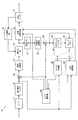
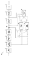
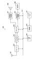
図1は、本発明の一実施形態に係る画像符号化装置10の構成の一例を示すブロック図である。図1を参照すると、画像符号化装置10は、A/D(Analogue to Digital)変換部11、並べ替えバッファ12、減算部13、直交変換部14、量子化部15、可逆符号化部16、蓄積バッファ17、レート制御部18、逆量子化部21、逆直交変換部22、加算部23、デブロックフィルタ24、フレームメモリ25、セレクタ26、イントラ予測部30、動き探索部40、及びモード選択部50を備える。
<1. Configuration Example of Image Encoding Device According to One Embodiment>
[1-1. Overall configuration example]
FIG. 1 is a block diagram showing an example of the configuration of an
A/D変換部11は、アナログ形式で入力される画像信号をデジタル形式の画像データに変換し、一連のデジタル画像データを並べ替えバッファ12へ出力する。
The A /
並べ替えバッファ12は、A/D変換部11から入力される一連の画像データに含まれる画像を並べ替える。並べ替えバッファ12は、符号化処理に係るGOP(Group of Pictures)構造に応じて画像を並べ替えた後、並べ替え後の画像データを減算部13、イントラ予測部30及び動き探索部40へ出力する。
The
減算部13には、並べ替えバッファ12から入力される画像データ、及び後に説明するモード選択部50により選択される予測画像データが供給される。減算部13は、並べ替えバッファ12から入力される画像データとモード選択部50から入力される予測画像データとの差分である予測誤差データを算出し、算出した予測誤差データを直交変換部14へ出力する。
The
直交変換部14は、減算部13から入力される予測誤差データについて直交変換を行う。直交変換部14により実行される直交変換は、例えば、離散コサイン変換(Discrete Cosine Transform:DCT)又はカルーネン・レーベ変換などであってよい。直交変換部14は、直交変換処理により取得される変換係数データを量子化部15へ出力する。
The
量子化部15には、直交変換部14から入力される変換係数データ、及び後に説明するレート制御部18からのレート制御信号が供給される。量子化部15は、変換係数データを量子化し、量子化後の変換係数データ(以下、量子化データという)を可逆符号化部16及び逆量子化部21へ出力する。また、量子化部15は、レート制御部18からのレート制御信号に基づいて量子化パラメータ(量子化スケール)を切り替えることにより、可逆符号化部16に入力される量子化データのビットレートを変化させる。
The
可逆符号化部16には、量子化部15から入力される量子化データ、及び、後に説明するイントラ予測部30又は動き探索部40により生成されモード選択部50により選択されるイントラ予測又はインター予測に関する情報が供給される。イントラ予測に関する情報は、例えば、ブロックごとの最適なイントラ予測モードを示す予測モード情報を含み得る。また、インター予測に関する情報は、例えば、各ブロックを分割した境界を特定する分割情報、各領域について動きベクトルの予測のために使用された予測式を特定する予測式情報、差分動きベクトル情報、及び参照画像情報などを含み得る。
The
可逆符号化部16は、量子化データについて可逆符号化処理を行うことにより、符号化ストリームを生成する。可逆符号化部16による可逆符号化は、例えば、可変長符号化、又は算術符号化などであってよい。また、可逆符号化部16は、上述したイントラ予測に関する情報又はインター予測に関する情報を、符号化ストリームのヘッダ(例えばブロックヘッダ又はスライスヘッダなど)内に多重化する。そして、可逆符号化部16は、生成した符号化ストリームを蓄積バッファ17へ出力する。
The
蓄積バッファ17は、可逆符号化部16から入力される符号化ストリームを半導体メモリなどの記憶媒体を用いて一時的に蓄積する。そして、蓄積バッファ17は、蓄積した符号化ストリームを、伝送路(又は画像符号化装置10からの出力線)の帯域に応じたレートで出力する。
The
レート制御部18は、蓄積バッファ17の空き容量を監視する。そして、レート制御部18は、蓄積バッファ17の空き容量に応じてレート制御信号を生成し、生成したレート制御信号を量子化部15へ出力する。例えば、レート制御部18は、蓄積バッファ17の空き容量が少ない時には、量子化データのビットレートを低下させるためのレート制御信号を生成する。また、例えば、レート制御部18は、蓄積バッファ17の空き容量が十分大きい時には、量子化データのビットレートを高めるためのレート制御信号を生成する。
The
逆量子化部21は、量子化部15から入力される量子化データについて逆量子化処理を行う。そして、逆量子化部21は、逆量子化処理により取得される変換係数データを、逆直交変換部22へ出力する。
The
逆直交変換部22は、逆量子化部21から入力される変換係数データについて逆直交変換処理を行うことにより、予測誤差データを復元する。そして、逆直交変換部22は、復元した予測誤差データを加算部23へ出力する。
The inverse
加算部23は、逆直交変換部22から入力される復元された予測誤差データとモード選択部50から入力される予測画像データとを加算することにより、復号化画像データを生成する。そして、加算部23は、生成した復号化画像データをデブロックフィルタ24及びフレームメモリ25へ出力する。
The
デブロックフィルタ24は、画像の符号化時に生じるブロック歪みを減少させるためのフィルタリング処理を行う。デブロックフィルタ24は、加算部23から入力される復号化画像データをフィルタリングすることによりブロック歪みを除去し、フィルタリング後の復号化画像データをフレームメモリ25へ出力する。
The
フレームメモリ25は、加算部23から入力される復号化画像データ、及びデブロックフィルタ24から入力されるフィルタリング後の復号化画像データを記憶媒体を用いて記憶する。
The
セレクタ26は、イントラ予測のために使用されるフィルタリング前の復号化画像データをフレームメモリ25から読み出し、読み出した復号化画像データを参照画像データとしてイントラ予測部30に供給する。また、セレクタ26は、インター予測のために使用されるフィルタリング後の復号化画像データをフレームメモリ25から読み出し、読み出した復号化画像データを参照画像データとして動き探索部40に供給する。
The
イントラ予測部30は、並べ替えバッファ12から入力される符号化対象の画像データ、及びセレクタ26を介して供給される復号化画像データに基づいて、H.264/AVCにより規定されている各イントラ予測モードのイントラ予測処理を行う。例えば、イントラ予測部30は、各イントラ予測モードによる予測結果を所定のコスト関数を用いて評価する。そして、イントラ予測部30は、コスト関数値が最小となるイントラ予測モード、即ち圧縮率が最も高くなるイントラ予測モードを、最適なイントラ予測モードとして選択する。さらに、イントラ予測部30は、当該最適なイントラ予測モードを示す予測モード情報、予測画像データ、及びコスト関数値などのイントラ予測に関する情報を、モード選択部50へ出力する。さらに、イントラ予測部30は、並べ替えバッファ12から入力される符号化対象の画像データ、及びセレクタ26を介して供給される復号化画像データに基づいて、H.264/AVCにより規定されている各イントラ予測モードよりもサイズの大きいブロックでイントラ予測処理を行ってもよい。その場合にも、イントラ予測部30は、各イントラ予測モードによる予測結果を所定のコスト関数を用いて評価し、最適なイントラ予測モードについてのイントラ予測に関する情報をモード選択部50へ出力する。
Based on the image data to be encoded input from the
動き探索部40は、並べ替えバッファ12から入力される符号化対象の画像データ、及びフレームメモリ25から供給される参照画像データとしての復号化画像データ基づいて、画像内に設定される各ブロックを対象として動き探索処理を行う。
The
より具体的には、動き探索部40は、各ブロックを、複数の境界の候補によって複数の領域にそれぞれ分割する。ブロックを分割する境界の候補は、例えばH.264/AVCにおける水平方向又は垂直方向に沿った境界に加えて、図25及び図26に例示したような傾きを有する境界を含む。そして、動き探索部40は、参照画像の画素値と各領域内の原画像の画素値とに基づいて、各領域についての動きベクトルを算出する。
More specifically, the
また、動き探索部40は、各領域についての基準画素位置を境界の傾きに応じて適応的に設定する。そして、動き探索部40は、設定した基準画素位置に対応するブロック又は領域について既に算出した動きベクトルに基づいて、符号化対象の領域内の画素値の予測に使用すべき動きベクトルを領域ごとに予測する。動きベクトルの予測は、複数の予測式の候補についてそれぞれ行われ得る。複数の予測式の候補は、例えば、空間的相関若しくは時間的相関又はその双方を利用する予測式を含み得る。従って、動き探索部40は、境界の候補と予測式の候補との組合せごとに、各領域の動きベクトルを予測する。そして、動き探索部40は、所定のコスト関数に従ったコスト関数値が最小となる(即ち、圧縮率が最も高くなる)境界と予測式との組合せを、最適な組合せとして選択する。
In addition, the
このような動き探索部40による探索処理について、後に分割の具体的な例を挙げてさらに説明する。動き探索部40は、動き探索処理の結果として、最適な境界を特定する分割情報、最適な予測式を特定する予測式情報、差分動きベクトル情報、及びコスト関数値などのインター予測に関する情報と、予測画像データとを、モード選択部50へ出力する。
Such search processing by the
モード選択部50は、イントラ予測部30から入力されるイントラ予測に関するコスト関数値と動き探索部40から入力されるインター予測に関するコスト関数値とを比較する。そして、モード選択部50は、イントラ予測及びインター予測のうちコスト関数値がより少ない予測手法を選択する。モード選択部50は、イントラ予測を選択した場合には、イントラ予測に関する情報を可逆符号化部16へ出力すると共に、予測画像データを減算部13及び加算部23へ出力する。また、モード選択部50は、インター予測を選択した場合には、インター予測に関する上述した情報を可逆符号化部16へ出力すると共に、予測画像データを減算部13及び加算部23へ出力する。
The
[1−2.動き探索部の構成例]
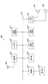
図2は、図1に示した画像符号化装置10の動き探索部40の詳細な構成の一例を示すブロック図である。図2を参照すると、動き探索部40は、分割部41、動きベクトル算出部42、基準画素設定部43、動きベクトルバッファ44、動きベクトル予測部45、選択部46、及び動き補償部47を有する。
[1-2. Configuration example of motion search unit]
FIG. 2 is a block diagram illustrating an example of a detailed configuration of the
分割部41は、画像内に設定されるブロックを、傾きを有する境界を含む複数の候補から選択される境界により、複数の領域に分割する。
The dividing
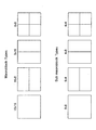
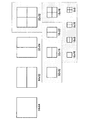
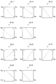
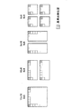
分割部41は、例えば、図3及び図4に示すように、画像内に設定されるブロックを傾きのない水平方向又は垂直方向に沿った境界の候補によって分割してもよい。この場合、分割により形成される各領域は、矩形領域となる。図3の例では、16×16画素の最大マクロブロックは、水平の境界により16×8画素の2つのブロックに分割され得る。また、16×16画素の最大マクロブロックは、垂直な境界により8×16画素の2つのブロックに分割され得る。また、16×16画素の最大マクロブロックは、水平の境界及び垂直の境界により8×8画素の4つのブロックに分割され得る。さらに、8×8画素のマクロブロックは、8×4画素の2つのサブマクロブロック、4×8画素の2つのサブマクロブロック、又は4×4画素の4つのサブマクロブロックに分割され得る。また、分割部41は、例えば、図4に示したように、H.264/AVCによりサポートされる16×16画素の最大マクロブロックよりも大きい、拡張されたサイズ(例えば64×64画素)を有するブロックを矩形領域に分割してもよい。
For example, as illustrated in FIGS. 3 and 4, the dividing
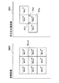
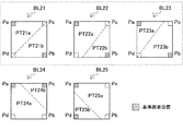
また、分割部41は、例えば、図5に示したように、画像内に設定されるブロックを傾きを有する境界の候補によって分割する。この場合、分割により形成される各領域は、非矩形領域となり得る。図5の例では、傾きを有する境界により分割される10通りのブロックBL11〜BL15、BL21〜BL25が示されている。なお、ジオメトリ動き分割においては、傾きを有する境界のブロック内での位置及び傾きは、距離ρ及び傾き角θにより特定される(図25参照)。分割部41は、例えば、距離ρ及び傾き角θの値の候補を離散的にいくつか指定する。この場合、指定された距離ρ及び傾き角θの組合せにより特定される境界が、ブロックを分割する境界の候補となる。図5の例では、分割により形成される各領域の形状は、三角形、台形、又は五角形である。
Further, for example, as illustrated in FIG. 5, the dividing
分割部41は、このような複数の候補としての境界(即ち、複数の分割のパターン)でブロックを分割し、それら候補としての境界を特定する分割情報を、動きベクトル算出部42及び基準画素設定部43へ出力する。分割情報は、例えば、矩形分割又はジオメトリ動き分割のいずれかを指定する分割モード情報、並びに境界の位置と傾きとを指定する境界パラメータ(例えば、上述した距離ρ及び傾き角θ)を含み得る。
The dividing
動きベクトル算出部43は、分割部41から入力される分割情報により特定される各領域について、原画像の画素値、及びフレームメモリ25から入力される参照画像の画素値に基づいて、動きベクトルを算出する。動きベクトルの算出に際しては、動きベクトル算出部43は、例えば、隣り合う画素間の中間的な画素値を線型内挿処理により補間し、1/2画素精度で動きベクトルを算出してもよい。また、動きベクトル算出部43は、例えば、6タップのFIRフィルタを用いてさらに中間的な画素値を補間し、1/4画素精度で動きベクトルを算出してもよい。動きベクトル算出部43は、算出した動きベクトルを、動きベクトル予測部45へ出力する。
The motion
基準画素設定部43は、ブロックを分割した境界の傾きに応じて、各ブロック内の各領域の基準画素位置を設定する。例えば、基準画素設定部43は、傾きのない水平方向又は垂直方向に沿った境界によりブロックが分割される場合には、分割により形成される矩形領域の左上及び右上の画素位置を、動きベクトルの予測のための基準画素位置として設定する。一方、基準画素設定部43は、ジオメトリ動き分割の場合のように、傾きを有する境界によりブロックが分割される場合には、分割により形成される非矩形領域に、境界の傾きに応じて適応的に基準画素位置を設定する。基準画素設定部43により設定される基準画素位置について、後に例を挙げてさらに説明する。
The reference
動きベクトルバッファ44は、動きベクトル予測部45による動きベクトル予測処理において参照される参照動きベクトルを、記憶媒体を用いて一時的に記憶する。動きベクトル予測処理において参照される動きベクトルとは、符号化済みの参照画像内のブロック又は領域に設定された動きベクトル、及び符号化対象の画像内の他のブロック又は領域に設定された動きベクトルを含み得る。
The
動きベクトル予測部45は、基準画素設定部43により設定される基準画素位置に対応するブロック又は領域に設定された動きベクトルに基づいて、分割部41により分割されるブロック内の各領域内の画素値の予測に使用すべき動きベクトルを予測する。ここで、上述したように、「基準画素位置に対応するブロック又は領域」とは、例えば、基準画素に隣接する画素が属するブロック又は領域を含み得る。また、「基準画素位置に対応するブロック又は領域」とは、例えば、参照画像内の基準画素と同じ位置の画素が属するブロック又は領域を含み得る。
The motion
動きベクトル予測部45は、ある1つの領域について、複数の予測式の候補を用いて、複数の動きベクトルを予測してもよい。例えば、第1の予測式は動きの空間的相関を利用する予測式であり、第2の予測式は動きの時間的相関を利用する予測式であってよい。また、第3の予測式として、動きの空間的相関と時間的相関の双方を利用する予測式が使用されてもよい。動きの空間的相関を利用する場合、動きベクトル予測部45は、例えば、動きベクトルバッファ44に記憶されている、基準画素位置に隣接する他のブロック又は領域に設定された参照動きベクトルを参照する。また、動きの時間的相関を利用する場合、動きベクトル予測部45は、例えば、動きベクトルバッファ44に記憶されている、基準画素位置とコロケーテッドな参照画像内のブロック又は領域に設定された参照動きベクトルを参照する。動きベクトル予測部45が使用し得る予測式について、後に例を挙げてさらに説明する。
The motion
動きベクトル予測部45は、ある境界に係る領域について1つの予測式を用いて予測動きベクトルを算出すると、動きベクトル算出部42により算出された動きベクトルと当該予測動きベクトルとの差分を表す差分動きベクトルを算出する。そして、動きベクトル予測部45は、上記境界を特定する分割情報及び上記予測式を特定する予測式情報と関連付けて、算出した差分動きベクトル及び参照画像情報を、選択部46へ出力する。
When the motion
選択部46は、動きベクトル予測部45から入力される分割情報、予測式情報及び差分動きベクトルを用いて、コスト関数値を最小にする最適な境界と最適な予測式との組合せを選択する。そして、選択部46は、選択した最適な境界を特定する分割情報、最適な予測式を特定する予測式情報、対応する差分動きベクトル情報、参照画像情報、及び対応するコスト関数値などを、動き補償部47へ出力する。
The
動き補償部47は、選択部46により選択された最適な境界、最適な予測式、差分動きベクトル、及びフレームメモリ25から入力される参照画像データを用いて、予測画像データを生成する。そして、動き補償部47は、生成した予測画像データ、並びに、選択部46から入力された分割情報、予測式情報、差分動きベクトル情報及びコスト関数値などのインター予測に関する情報を、モード選択部50へ出力する。また、動き補償部47は、予測画像データの生成に用いた動きベクトル、即ち各領域に最終的に設定した動きベクトルを、動きベクトルバッファ44に記憶させる。
The
[1−3.動きベクトル予測処理の説明]
次に、上述した動きベクトル予測部43による動きベクトル予測処理についてより具体的に説明する。
[1-3. Explanation of motion vector prediction process]
Next, the motion vector prediction process by the motion
(1)矩形領域での動きベクトルの予測
(1−1)基準画素位置
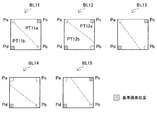
図6は、矩形領域に設定され得る基準画素位置について説明するための説明図である。図6を参照すると、境界により分割されていない矩形ブロック(16×16画素)、及び、水平又は垂直な境界によりそれぞれ分割された矩形領域が示されている。基準画素設定部43は、これら矩形領域については、動きベクトルの予測のための基準画素位置を、各領域内の左上若しくは右上又はその双方に一律的に設定する。図6においては、これら基準画素位置が、斜線の網掛けにより示されている。なお、H.264/AVCでは、8×16画素の領域の基準画素位置は、ブロック内で左側の領域については左上、ブロック内で右側の領域については右上に設定される。
(1) Prediction of motion vector in rectangular area (1-1) Reference pixel position FIG. 6 is an explanatory diagram for explaining reference pixel positions that can be set in the rectangular area. Referring to FIG. 6, a rectangular block (16 × 16 pixels) that is not divided by a boundary and a rectangular area that is divided by a horizontal or vertical boundary are shown. For these rectangular areas, the reference
(1−2)空間的予測
図7は、矩形領域における空間的予測について説明するための説明図である。図7を参照すると、1つの矩形領域PTeに設定され得る2つの基準画素位置PX1及びPX2が示されている。動きの空間的相関を利用する予測式は、例えば、これら基準画素位置PX1及びPX2に隣接する他のブロック又は領域に設定された動きベクトルを入力とする。なお、本明細書において、「隣接する」という用語は、例えば、2つのブロック、領域又は画素が辺を共有する場合のみならず、頂点を共有する場合をも含むものとする。
(1-2) Spatial Prediction FIG. 7 is an explanatory diagram for describing spatial prediction in a rectangular region. Referring to FIG. 7, two reference pixel positions PX1 and PX2 that can be set in one rectangular area PTe are shown. The prediction formula using the spatial correlation of motion receives, for example, motion vectors set in other blocks or regions adjacent to these reference pixel positions PX1 and PX2. In this specification, the term “adjacent” includes, for example, not only the case where two blocks, regions, or pixels share a side but also a case where a vertex is shared.
例えば、基準画素位置PX1の左の画素が属するブロックBLaに設定された動きベクトルをMVaとする。また、基準画素位置PX1の上の画素が属するブロックBLbに設定された動きベクトルをMVbとする。また、基準画素位置PX2の右上の画素が属するブロックBLcに設定された動きベクトルをMVcとする。これら動きベクトルMVa、MVb及びMVcは、既に符号化済みである。符号化対象のブロック内の矩形領域PTeについての予測動きベクトルPMVeは、次のような予測式を用いて、動きベクトルMVa、MVb及びMVcから算出され得る。 For example, the motion vector set in the block BLa to which the left pixel of the reference pixel position PX1 belongs is assumed to be MVa. Further, a motion vector set to the block BLb to which the pixel above the reference pixel position PX1 belongs is assumed to be MVb. Further, a motion vector set to the block BLc to which the upper right pixel of the reference pixel position PX2 belongs is assumed to be MVc. These motion vectors MVa, MVb, and MVc have already been encoded. The predicted motion vector PMVe for the rectangular area PTe in the block to be encoded can be calculated from the motion vectors MVa, MVb, and MVc using the following prediction formula.

ここで、式(1)におけるmedはメディアンオペレーションを表す。即ち、式(1)によれば、予測動きベクトルPMVeは、動きベクトルMVa、MVb及びMVcの水平成分の中央値と垂直成分の中央値とを成分とするベクトルである。なお、上記式(1)は、空間的相関を利用する予測式の一例に過ぎない。例えば、符号化対象のブロックが画像の端部に位置するために、動きベクトルMVa、MVb又はMVcのいずれかが存在しない場合には、存在しない動きベクトルは、メディアンオペレーションの引数から省略されてもよい。また、例えば、符号化対象のブロックが画像の右端に位置する場合には、動きベクトルMVcの代わりに、図7に示したブロックBLdに設定された動きベクトルが使用されてもよい。 Here, med in equation (1) represents a median operation. That is, according to the equation (1), the predicted motion vector PMVe is a vector having the central value of the horizontal component and the central value of the vertical component of the motion vectors MVa, MVb, and MVc as components. In addition, the said Formula (1) is only an example of the prediction formula using a spatial correlation. For example, if any of the motion vectors MVa, MVb, or MVc does not exist because the encoding target block is located at the end of the image, the non-existing motion vector may be omitted from the median operation argument. Good. For example, when the block to be encoded is located at the right end of the image, the motion vector set in the block BLd shown in FIG. 7 may be used instead of the motion vector MVc.
なお、予測動きベクトルPMVeは、プレディクタ(predictor)とも呼ばれる。特に、式(1)のように、動きの空間的相関を利用する予測式によって算出される予測動きベクトルを、空間的プレディクタ(spatial predictor)という。一方、次項で説明する動きの時間的相関を利用する予測式によって算出される予測動きベクトルを、時間的プレディクタ(temporal predictor)という。 Note that the predicted motion vector PMVe is also called a predictor. In particular, as in Expression (1), a predicted motion vector calculated by a prediction expression that uses a spatial correlation of motion is referred to as a spatial predictor. On the other hand, a predicted motion vector calculated by a prediction formula that uses temporal correlation of motion described in the next section is referred to as a temporal predictor.
動きベクトル予測部45は、このように予測動きベクトルPMVeを決定した後、次式のように、動きベクトル算出部42により算出された動きベクトルMVeと予測動きベクトルPMVeとの差分を表す差分動きベクトルMVDeを算出する。
After determining the motion vector predictor PMVe in this manner, the motion
動き探索部40からインター予測に関する情報の1つとして出力される差分動きベクトル情報は、この差分動きベクトルMVDeを表す。そして、差分動きベクトル情報は、可逆符号化部16により符号化され、画像を復号化する装置へ伝送され得る。
The differential motion vector information output as one piece of information related to inter prediction from the
(1−3)時間的予測
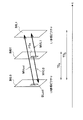
図8は、矩形領域における時間的予測について説明するための説明図である。図8を参照すると、符号化対象領域PTeを含む符号化対象画像IM01、及び参照画像IM02が示されている。参照画像IM02内のブロックBLcolは、参照画像IM02内で基準画素位置PX1又はPX2と共通する位置の画素を含む、いわゆるコロケーテッドブロックである。動きの時間的相関を利用する予測式は、例えば、このコロケーテッドブロックBLcol又はコロケーテッドブロックBLcolに隣接するブロック(又は領域)に設定された動きベクトルを入力とする。
(1-3) Temporal Prediction FIG. 8 is an explanatory diagram for describing temporal prediction in a rectangular region. Referring to FIG. 8, a coding target image IM01 including a coding target region PTe and a reference image IM02 are shown. The block BLcol in the reference image IM02 is a so-called collocated block including a pixel at a position common to the base pixel position PX1 or PX2 in the reference image IM02. The prediction formula using the temporal correlation of motion is, for example, input with a motion vector set in the collocated block BLcol or a block (or region) adjacent to the collocated block BLcol.
例えば、コロケーテッドブロックBLcolに設定された動きベクトルをMVcolとする。また、コロケーテッドブロックBLcolの上、左、下、右、左上、左下、右下及び右上のブロックに設定された動きベクトルを、それぞれMVt0〜MVt7とする。これら動きベクトルMVcol及びMVt0〜MVt7は、既に符号化済みである。この場合、予測動きベクトルPMVeは、例えば、次の予測式(3)又は(4)を用いて、動きベクトルMVcol及びMVt0〜MVt7から算出され得る。 For example, a motion vector set in the collocated block BLcol is MVcol. In addition, the motion vectors set in the upper, left, lower, right, upper left, lower left, lower right, and upper right blocks of the collocated block BLcol are MVt0 to MVt7, respectively. These motion vectors MVcol and MVt0 to MVt7 have already been encoded. In this case, the predicted motion vector PMVe can be calculated from the motion vectors MVcol and MVt0 to MVt7 using, for example, the following prediction formula (3) or (4).
また、動きの空間的相関及び時間的相関の双方を利用する次のような予測式が用いられてもよい。なお、動きベクトルルMVa、MVb及びMVcは、基準画素位置PX1又はPX2に隣接するブロックに設定された動きベクトルである。 In addition, the following prediction formula using both spatial correlation and temporal correlation of motion may be used. Note that the motion vectors MVa, MVb, and MVc are motion vectors set in a block adjacent to the reference pixel position PX1 or PX2.
![]()
![]()
この場合にも、動きベクトル予測部45は、予測動きベクトルPMVeを決定した後、動きベクトル算出部42により算出された動きベクトルMVeと予測動きベクトルPMVeとの差分を表す差分動きベクトルMVDeを算出する。そして、境界と予測式との最適な組合せに係る差分動きベクトルMVDeを表す差分動きベクトル情報が、動き探索部40から出力され、可逆符号化部16により符号化され得る。
Also in this case, after determining the predicted motion vector PMVe, the motion
なお、図8の例では1つの符号化対象画像IM01について1つの参照画像IM02のみを示しているが、1つの符号化対象画像IM01内で領域ごとに異なる参照画像が使用されてもよい。図9の例では、符号化対象画像IM01内の領域PTe1の動きベクトルの予測の際に参照される参照画像はIM021であり、領域PTe2の動きベクトルの予測の際に参照される参照画像はIM022である。このような参照画像の設定手法を、マルチ参照フレーム(Multi-Reference Frame)という。 In the example of FIG. 8, only one reference image IM02 is shown for one encoding target image IM01, but different reference images may be used for each region in one encoding target image IM01. In the example of FIG. 9, the reference image referred to when predicting the motion vector of the region PTe1 in the encoding target image IM01 is IM021, and the reference image referred to when predicting the motion vector of the region PTe2 is IM022. It is. Such a reference image setting method is referred to as a multi-reference frame.
(2)ダイレクトモード
なお、動きベクトル情報の情報量の増加に伴う圧縮率の低下を回避するために、H.264/AVCは、主にBピクチャを対象として、いわゆるダイレクトモードを導入している。ダイレクトモードにおいては、動きベクトル情報は符号化されず、符号化済みのブロックの動きベクトル情報から符号化対象のブロックの動きベクトル情報が生成される。ダイレクトモードは、空間ダイレクトモード(Spatial Direct Mode)、及び時間ダイレクトモード(Temporal Direct Mode)を含み、例えばスライスごとにこれら2つのモードが切り替えられ得る。本実施形態においても、このようなダイレクトモードが利用されてよい。
(2) Direct mode In order to avoid a decrease in compression rate accompanying an increase in the amount of motion vector information, H. H.264 / AVC introduces a so-called direct mode mainly for B pictures. In the direct mode, the motion vector information is not encoded, and the motion vector information of the block to be encoded is generated from the motion vector information of the encoded block. The direct mode includes a spatial direct mode and a temporal direct mode. For example, these two modes can be switched for each slice. Also in this embodiment, such a direct mode may be used.
例えば、空間ダイレクトモードにおいては、符号化対象の領域についての動きベクトルMVeは、上述した予測式(1)を用いて、次式のように決定され得る。 For example, in the spatial direct mode, the motion vector MVe for the region to be encoded can be determined as follows using the prediction equation (1) described above.
図10は、時間ダイレクトモードについて説明するための説明図である。図10において、符号化対象画像IM01のL0参照ピクチャである参照画像IML0、及び符号化対象画像IM01のL1参照ピクチャである参照画像IML1が示されている。参照画像IML0内のブロックBLcolは、符号化対象画像IM01内の符号化対象領域PTeのコロケーテッドブロックである。ここで、コロケーテッドブロックBLcolに設定された動きベクトルをMVcolとする。また、符号化対象画像IM01と参照画像IML0との間の時間軸上の距離をTDB、参照画像IML0と参照画像IML1との間の時間軸上の距離をTDDとする。すると、時間ダイレクトモードにおいては、符号化対象領域PTeについての動きベクトルMVL0及びMVL1は、次式のように決定され得る。 FIG. 10 is an explanatory diagram for explaining the time direct mode. FIG. 10 shows a reference image IML0 that is an L0 reference picture of the encoding target image IM01 and a reference image IML1 that is an L1 reference picture of the encoding target image IM01. The block BLcol in the reference image IML0 is a collocated block of the encoding target region PTe in the encoding target image IM01. Here, the motion vector set in the collocated block BLcol is MVcol. Also, the distance on the time axis between the encoding target image IM01 and the reference image IML0 is TD B , and the distance on the time axis between the reference image IML0 and the reference image IML1 is TD D. Then, in the temporal direct mode, motion vectors MVL0 and MVL1 for the encoding target region PTe can be determined as in the following equation.
なお、時間軸上の距離を表す指標として、POC(Picture Order Count)が使用されてもよい。このようなダイレクトモードの利用の有無は、例えば、ブロック単位で指定され得る。 Note that POC (Picture Order Count) may be used as an index representing the distance on the time axis. Whether or not such direct mode is used can be specified, for example, in units of blocks.
(3)非矩形領域での動きベクトルの予測
上述したように、矩形領域については、例えば左上又は右上の画素というように、基準画素位置を一律的に定義付けることができる。これに対し、ジオメトリ動き分割の場合のように、傾きを有する境界によりブロックが分割される場合には、分割により形成される非矩形領域の形状が様々であることから、基準画素位置を適応的に設定することが望ましい。
(3) Prediction of motion vector in non-rectangular area As described above, for the rectangular area, the reference pixel position can be uniformly defined, for example, the upper left or upper right pixel. On the other hand, when a block is divided by a boundary having an inclination as in the case of geometry motion division, the shape of the non-rectangular area formed by the division is various, so the reference pixel position is adaptive. It is desirable to set to.
(3−1)基準画素位置
図11〜図13は、非矩形領域に設定され得る基準画素位置について説明するための説明図である。図11に示した5つのブロックBL11〜BL15は、図5に示した10個のブロックのうち、境界が左上のコーナーに位置する画素Pa及び右下のコーナーに位置する画素Pbの一方又は双方に重なっているブロックである。境界が直線であれば、この場合、分割により形成される2つの領域の一方は右上のコーナーに位置する画素Pcを含み、他方は左下のコーナーに位置する画素Pdを含む。そこで、図11に例示したケースにおいては、基準画素設定部43は、各領域の基準画素位置を、画素Pc及び画素Pdの位置にそれぞれ設定する。図11の例では、ブロックBL11の領域PT11aの基準画素位置は画素Pcの位置に設定されている。ブロックBL11の領域PT11bの基準画素位置は画素Pdの位置に設定されている。同様に、ブロックBL12の領域PT12aの基準画素位置は画素Pcの位置に設定されている。ブロックBL12の領域PT12bの基準画素位置は画素Pdの位置に設定されている。なお、ブロックの形状の対象性から、基準画素設定部43は、例えば、境界が右上のコーナー及び左下のコーナーの少なくとも一方に重なる場合に、各領域の基準画素位置を、左上のコーナー及び右下のコーナーにそれぞれ設定してもよい。
(3-1) Reference Pixel Position FIGS. 11 to 13 are explanatory diagrams for explaining reference pixel positions that can be set in a non-rectangular region. The five blocks BL11 to BL15 shown in FIG. 11 include, among the 10 blocks shown in FIG. 5, one or both of the pixel Pa whose boundary is located in the upper left corner and the pixel Pb located in the lower right corner. It is an overlapping block. If the boundary is a straight line, in this case, one of the two regions formed by the division includes the pixel Pc located in the upper right corner, and the other includes the pixel Pd located in the lower left corner. Therefore, in the case illustrated in FIG. 11, the reference
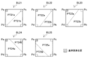
図12に示した5つのブロックBL21〜BL25は、図5に示した10個のブロックのうち、境界が左上のコーナー及び右下のコーナーのいずれにも重なっていないブロックである。この場合、基準画素設定部43は、例えば、左上のコーナーが属する第1の領域の基準画素位置を、左上のコーナー上に設定する。図12の例では、ブロックBL21の領域PT21aの基準画素位置は画素Paの位置に設定されている。同様に、ブロックBL22の領域PT22a、ブロックBL23の領域PT23a、ブロックBL24の領域PT24a、及びブロックBL25の領域PT25aの基準画素位置もまた、それぞれ画素Paの位置に設定されている。
The five blocks BL21 to BL25 shown in FIG. 12 are blocks whose boundaries do not overlap with either the upper left corner or the lower right corner among the ten blocks shown in FIG. In this case, for example, the reference
また、基準画素設定部43は、境界が左上のコーナー及び右下のコーナーのいずれにも重なっておらず、左上のコーナーが属する第1の領域ではない第2の領域に右下のコーナーが属する場合には、第2の領域の基準画素位置を、右下のコーナー上に設定する。図13を参照すると、ブロックBL21の領域PT21bの基準画素位置は画素Pbの位置に設定されている。同様に、ブロックBL22の領域PT22b、及びブロックBL23の領域PT23bの基準画素位置もまた、それぞれ画素Pbの位置に設定されている。
Further, the reference
さらに、基準画素設定部43は、第2の領域に右下のコーナーが属さず、第2の領域に右上のコーナーが属する場合には、第2の領域の基準画素位置を、右上のコーナー上に設定する。図13を参照すると、ブロックBL24の領域PT24bの基準画素位置は、画素Pcの位置に設定されている。そして、ここまでのいずれのケースに該当しない場合には、基準画素設定部43は、第2の領域の基準画素位置を、左下のコーナー上に設定する。図13を参照すると、ブロックBL25の領域PT25bの基準画素位置は、画素Pdの位置に設定されている。
Further, when the lower right corner does not belong to the second area and the upper right corner belongs to the second area, the reference
(3−2)空間的予測
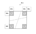
図14は、図11〜図13に例示したような非矩形領域における、空間的予測について説明するための説明図である。図14を参照すると、符号化対象ブロックBLe内の各領域の基準画素位置として設定され得る4つの画素位置Pa〜Pdが示されている。また、画素位置Paに、ブロックNBa及びNBbが隣接している。画素位置Pcには、ブロックNBc及びNBeが隣接している。画素位置Pdには、ブロックNBfが隣接している。非矩形領域についての動きの空間的相関を利用する予測式は、例えば、基準画素位置Pa〜Pdに隣接するこれら隣接ブロック(又は領域)NBa〜NBfに設定された動きベクトルを入力とする予測式であってよい。
(3-2) Spatial Prediction FIG. 14 is an explanatory diagram for describing spatial prediction in a non-rectangular region illustrated in FIGS. 11 to 13. Referring to FIG. 14, four pixel positions Pa to Pd that can be set as reference pixel positions of each region in the encoding target block BLe are shown. Further, the blocks NBa and NBb are adjacent to the pixel position Pa. Blocks NBc and NBe are adjacent to the pixel position Pc. The block NBf is adjacent to the pixel position Pd. The prediction formula using the spatial correlation of the motion for the non-rectangular region is, for example, a prediction formula using as input the motion vectors set in these adjacent blocks (or regions) NBa to NBf adjacent to the reference pixel positions Pa to Pd. It may be.
式(9)及び式(10)は、それぞれ、基準画素位置が左上のコーナー(画素位置Pa)である領域についての予測動きベクトルPMVeを予測するための予測式の一例である。なお、動きベクトルMVni(i=a,b,…,f)は、隣接ブロックNBiに設定された動きベクトルを表す。 Expressions (9) and (10) are examples of prediction expressions for predicting the predicted motion vector PMVe for a region whose reference pixel position is the upper left corner (pixel position Pa). Note that the motion vector MVni (i = a, b,..., F) represents a motion vector set in the adjacent block NBi.
式(9)及び式(10)は、最も単純な予測式の一例である。しかし、予測式として、他の式が使用されてもよい。例えば、領域が左上及び右上のコーナーを共に含む場合には、図7を用いて説明した矩形領域についての空間的予測と同様に、隣接ブロックNBa、NBb及びNBcに設定された動きベクトルに基づく予測式が使用されてもよい。この場合の予測式は、式(1)と同様である。 Expressions (9) and (10) are examples of the simplest prediction expression. However, other formulas may be used as the prediction formula. For example, when the region includes both the upper left corner and the upper right corner, the prediction based on the motion vectors set in the adjacent blocks NBa, NBb, and NBc is performed in the same manner as the spatial prediction for the rectangular region described with reference to FIG. An expression may be used. The prediction formula in this case is the same as formula (1).
なお、基準画素位置が右下のコーナー(画素位置Pb)である領域については、隣接ブロックが符号化済みでないため、隣接ブロック(又は領域)に設定された動きベクトルを使用することができない。この場合には、動きベクトル予測部45は、空間的相関に基づく予測動きベクトルをゼロベクトルとしてもよい。
It should be noted that the motion vector set in the adjacent block (or region) cannot be used for the region whose reference pixel position is the lower right corner (pixel position Pb) because the adjacent block has not been encoded. In this case, the motion
(3−3)時間的予測
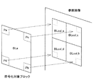
図15は、非矩形領域における時間的予測について説明するための説明図である。図15を参照すると、符号化対象ブロックBLe内の各領域の基準画素位置として設定され得る4つの画素位置Pa〜Pdが示されている。基準画素位置が画素位置Paである場合、参照画像内のコロケーテッドブロックはブロックBLcol_aとなる。基準画素位置が画素位置Pbである場合、参照画像内のコロケーテッドブロックはブロックBLcol_bとなる。基準画素位置が画素位置Pcである場合、参照画像内のコロケーテッドブロックはブロックBLcol_cとなる。基準画素位置が画素位置Pdである場合、参照画像内のコロケーテッドブロックはブロックBLcol_dとなる。動きベクトル予測部45は、基準画素設定部43により設定される基準画素位置に応じて、このようにコロケーテッドブロック(又はコロケーテッド領域)BLcolを認識する。また、動きベクトル予測部45は、例えば、図8を用いて説明したように、コロケーテッドブロック(又はコロケーテッド領域)BLcolに隣接するブロック又は領域をさらに認識する。そして、動きベクトル予測部45は、基準画素位置に対応するこれら参照画像内のブロック又は領域に設定された動きベクトルMVcol及びMVt0〜MVt7(図8参照)を用いて、動きの時間的相関を利用する予測式に従って、予測動きベクトルを算出することができる。この場合の予測式は、例えば、式(3)及び式(4)と同様であってよい。
(3-3) Temporal Prediction FIG. 15 is an explanatory diagram for describing temporal prediction in a non-rectangular region. Referring to FIG. 15, four pixel positions Pa to Pd that can be set as reference pixel positions of each region in the encoding target block BLe are shown. When the reference pixel position is the pixel position Pa, the collocated block in the reference image is the block BLcol_a. When the reference pixel position is the pixel position Pb, the collocated block in the reference image is the block BLcol_b. When the reference pixel position is the pixel position Pc, the collocated block in the reference image is the block BLcol_c. When the reference pixel position is the pixel position Pd, the collocated block in the reference image is the block BLcol_d. The motion
(3−4)時空間的予測
また、動きベクトル予測部45は、非矩形領域についても、動きの空間的相関及び時間的相関の双方を利用する予測式を用いてよい。その場合には、動きベクトル予測部45は、図14を用いて説明した隣接ブロック(又は隣接領域)に設定された動きベクトルと、図15を用いて説明した参照画像内のコロケーテッドブロック(又はコロケーテッド領域)に設定された動きベクトルとに基づく予測式を使用することができる。この場合の予測式は、例えば、式(5)と同様であってよい。
(3-4) Spatiotemporal Prediction The motion
(4)予測式の選択
上述したように、動きベクトル予測部45は、動きベクトルの予測(予測動きベクトルの算出)に際して、空間的相関を利用する予測式、時間的相関を利用する予測式、及び時空間的相関を利用する予測式を、予測式の候補として使用し得る。また、動きベクトル予測部45は、例えば、時間的相関を利用する予測式として複数の予測式の候補を使用してもよい。動きベクトル予測部45は、このように、分割部41により設定される複数の境界の候補の各々について、さらに複数の予測式の候補ごとに、各領域についての予測動きベクトルを算出する。そして、選択部46は、境界の候補と予測式の候補との各組合せをコスト関数値により評価し、圧縮率が最も高くなる(最良の符号化効率を達成する)最適な組合せを選択する。その結果、例えば、画像内に設定されるブロックごとに、ブロックを分割する境界が変化すると共に、当該ブロックに適用される予測式もまた適応的に切り替えられ得る。
(4) Selection of prediction formula As described above, the motion
<2.一実施形態に係る符号化時の処理の流れ>
次に、図16及び図17を用いて、符号化時の処理の流れを説明する。
<2. Flow of processing during encoding according to one embodiment>
Next, a processing flow during encoding will be described with reference to FIGS. 16 and 17.
[2−1.動き探索処理]
図16は、本実施形態に係る動き探索部40による動き探索処理の流れの一例を示すフローチャートである。
[2-1. Motion search processing]
FIG. 16 is a flowchart illustrating an example of a flow of motion search processing by the
図16を参照すると、まず、分割部41は、傾きを有する境界を含む複数の境界の候補により、画像内に設定されるブロックを複数の領域に分割する(ステップS100)。例えば、第1の境界の候補は、H.264/AVCにおける水平方向又は垂直方向に沿った境界であり、第1の境界の候補によって、各ブロックは複数の矩形領域に分割され得る。また、例えば、第2の境界の候補は、ジオメトリ動き分割による傾きを有する境界(斜めの境界)であり、第2の境界の候補によって、各ブロックは複数の非矩形領域に分割され得る。
Referring to FIG. 16, first, the dividing
次に、動きベクトル算出部42は、参照画像の画素値と各領域内の原画像の画素値とに基づいて、各領域についての動きベクトルを算出する(ステップS110)。
Next, the motion
次に、基準画素設定部44は、ブロックを分割した境界の傾きに応じて、各領域に基準画素位置を設定する(ステップS120)。なお、基準画素設定部44による基準画素位置設定処理の流れについては、後により詳細に説明する。
Next, the reference
次に、動きベクトル予測部45は、分割部41により分割されたブロック内の各領域内の画素値の予測に使用すべき動きベクトルを、領域ごとに複数の予測式の候補を用いて予測する(ステップS140)。例えば、第1の予測式の候補は、上述した空間的相関を利用する予測式である。第2の予測式の候補は、上述した時間的相関を利用する予測式である。第3の予測式の候補は、上述した空間的相関及び時間的相関の双方を利用する予測式である。ここで、例えば、時間的相関を利用する予測式を使用するためには、符号化対象の領域と同じ位置の(即ち、コロケーテッドな)参照画像内のブロック又は領域を特定できることが重要である。本実施形態では、動きベクトル予測部45は、コロケーテッドなブロック又は領域を、境界の傾きに応じて変化する基準画素位置に基づいて特定し得る。そのため、例えば、分割により様々な形状の領域が形成され得るジオメトリ動き分割のような分割方式が使用される場合にも、動きの時間的相関を利用する動きベクトルの予測が可能である。
Next, the motion
次に、動きベクトル予測部45は、候補としての境界と予測式との組合せごとに、動きベクトル算出部42により算出された動きベクトルと予測動きベクトルとの差分を表す差分動きベクトルを算出する(ステップS150)。
Next, the motion
次に、選択部46は、動きベクトル予測部45による予測結果に基づいて、境界と予測式との各組合せについてのコスト関数値を評価し、最良の符号化効率を達成する境界と予測式との組合せを選択する(ステップS160)。選択部46に用いられるコスト関数は、例えば、原画像及び復号化後の画像の間の差分エネルギーと発生する符号量とに基づく関数であってよい。
Next, the
次に、動き補償部47は、選択部46により選択された最適な境界及び最適な予測式を用いて、符号化対象ブロック内の画素に関する予測画素値を算出し、予測画素データを生成する(ステップS170)。
Next, the
そして、動き補償部47は、インター予測に関する情報と予測画素データとをモード選択部50へ出力する(ステップS180)。インター予測に関する情報には、例えば、最適な境界を特定する分割情報、最適な予測式を特定する予測式情報、対応する差分動きベクトル情報、参照画像情報、及び対応するコスト関数値などが含まれ得る。なお、最終的に各ブロック内の各領域に設定された動きベクトルは、参照動きベクトルとして動きベクトルバッファ44により記憶される。
Then, the
[2−2.基準画素位置設定処理]
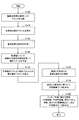
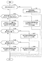
図17は、図16のステップS120の処理に相当する、本実施形態に係る基準画素位置設定処理の流れの一例を示すフローチャートである。
[2-2. Reference pixel position setting process]
FIG. 17 is a flowchart illustrating an example of the flow of the reference pixel position setting process according to the present embodiment, which corresponds to the process of step S120 of FIG.
図17を参照すると、まず、基準画素設定部43は、ブロックを分割する候補としての境界が傾きを有するか否かを判定する(ステップS121)。例えば、境界が水平又は垂直である場合には、基準画素設定部43は、境界が傾きを有しないと判定する。その場合には、処理はステップS122へ進む。また、境界が水平又は垂直でない場合には、基準画素設定部43は、境界が傾きを有すると判定する。その場合には、処理はステップS123へ進む。
Referring to FIG. 17, first, the reference
ステップS122では、基準画素設定部43は、既存のH.264/AVCなどの画像符号化方式の例のように、図6に例示したように、各領域の左上又は右上のコーナーを基準画素位置として設定する(ステップS122)。
In step S122, the reference
ステップS123に処理が進んだ場合、各領域は、非矩形領域である。この場合、基準画素設定部43は、ブロックを分割する候補としての境界が、ブロックの互いに対角に位置する第1のコーナー及び第2のコーナーの少なくとも一方に重なるか否かを判定する(ステップS123)。第1のコーナー及び第2のコーナーの位置は、例えば、図11に例示した画素位置Pa及びPbにそれぞれ相当し得る。その代わりに、第1のコーナー及び第2のコーナーの位置は、例えば、図11に例示した画素位置Pc及びPdであってもよい。なお、本明細書において、「コーナーに重なる」という表現は、境界がブロックの頂点を通る場合のみならず、ブロックのコーナーに位置する画素上を境界が通過する場合も含むものとする。
When the process proceeds to step S123, each area is a non-rectangular area. In this case, the reference
ステップS123において、境界が第1及び第2のコーナーの少なくとも一方に重なると判定される場合には、基準画素設定部43は、図11に例示したように、2つの領域の基準画素位置を、第1のコーナー及び第2のコーナーとは異なる第3のコーナー及び第4のコーナー上にそれぞれ設定する(ステップS124)。
If it is determined in step S123 that the boundary overlaps at least one of the first and second corners, the reference
ステップS123において、境界が第1及び第2のコーナーのいずれにも重ならないと判定される場合には、基準画素設定部43は、図12に例示したように、第1のコーナーが属する第1の領域の基準画素位置を、第1のコーナー上に設定する(ステップS125)。
If it is determined in step S123 that the boundary does not overlap with any of the first and second corners, the reference
次に、基準画素設定部43は、第1のコーナーが属しない第2の領域に第2のコーナーが属するか否かを判定する(ステップS126)。
Next, the reference
ステップS126において、第1のコーナーが属しない第2の領域に第2のコーナーが属すると判定される場合には、基準画素設定部43は、図13のブロックBL21〜BL23の例のように、第2の領域の基準画素位置を第2のコーナー上に設定する(ステップS127)。
In step S126, when it is determined that the second corner belongs to the second region to which the first corner does not belong, the reference
ステップS126において、第1のコーナーが属しない第2の領域に第2のコーナーが属しないと判定される場合には、基準画素設定部43は、当該第2の領域に第3のコーナーが属するか否かをさらに判定する(ステップS128)。
In step S126, when it is determined that the second corner does not belong to the second region to which the first corner does not belong, the reference
ステップS128において、第2の領域に第3のコーナーが属すると判定される場合には、基準画素設定部43は、第2の領域の基準画素位置を第3のコーナー上に設定する(ステップS129)。
When it is determined in step S128 that the third corner belongs to the second area, the reference
ステップS128において、第2の領域に第3のコーナーが属しないと判定される場合には、基準画素設定部43は、第2の領域の基準画素位置を第4のコーナー上に設定する(ステップS130)。
If it is determined in step S128 that the third corner does not belong to the second area, the reference
このような基準画素位置設定処理により、ジオメトリ動き分割などのように、動き補償の処理単位である領域が矩形以外の様々な形状をとり得る場合であっても、各領域に適応的に基準画素位置を設定することができる。 Even if the region that is the processing unit for motion compensation can take various shapes other than a rectangle, such as geometry motion division, the reference pixel position can be adaptively applied to each region. The position can be set.
<3.一実施形態に係る画像復号化装置の構成例>
本節では、図18及び図19を用いて、本発明の一実施形態に係る画像復号化装置の構成例について説明する。
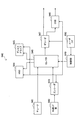
<3. Configuration Example of Image Decoding Device According to One Embodiment>
In this section, a configuration example of an image decoding apparatus according to an embodiment of the present invention will be described with reference to FIGS. 18 and 19.
[3−1.全体的な構成例]
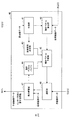
図18は、本発明の一実施形態に係る画像復号化装置60の構成の一例を示すブロック図である。図18を参照すると、画像復号化装置60は、蓄積バッファ61、可逆復号化部62、逆量子化部63、逆直交変換部64、加算部65、デブロックフィルタ66、並べ替えバッファ67、D/A(Digital to Analogue)変換部68、フレームメモリ69、セレクタ70及び71、イントラ予測部80、並びに動き補償部90を備える。
[3-1. Overall configuration example]
FIG. 18 is a block diagram illustrating an example of the configuration of the
蓄積バッファ61は、伝送路を介して入力される符号化ストリームを記憶媒体を用いて一時的に蓄積する。
The
可逆復号化部62は、蓄積バッファ61から入力される符号化ストリームを、符号化の際に使用された符号化方式に従って復号化する。また、可逆復号化部62は、符号化ストリームのヘッダ領域に多重化されている情報を復号化する。符号化ストリームのヘッダ領域に多重化されている情報とは、例えば、ブロックヘッダ内のイントラ予測に関する情報及びインター予測に関する情報を含み得る。可逆復号化部62は、イントラ予測に関する情報をイントラ予測部80へ出力する。また、可逆復号化部62は、インター予測に関する情報を動き補償部90へ出力する。
The
逆量子化部63は、可逆復号化部62による復号化後の量子化データを逆量子化する。逆直交変換部64は、符号化の際に使用された直交変換方式に従い、逆量子化部63から入力される変換係数データについて逆直交変換を行うことにより、予測誤差データを生成する。そして、逆直交変換部64は、生成した予測誤差データを加算部65へ出力する。
The
加算部65は、逆直交変換部64から入力される予測誤差データと、セレクタ71から入力される予測画像データとを加算することにより、復号化画像データを生成する。そして、加算部65は、生成した復号化画像データをデブロックフィルタ66及びフレームメモリ69へ出力する。
The adding
デブロックフィルタ66は、加算部65から入力される復号化画像データをフィルタリングすることによりブロック歪みを除去し、フィルタリング後の復号化画像データを並べ替えバッファ67及びフレームメモリ69へ出力する。
The
並べ替えバッファ67は、デブロックフィルタ66から入力される画像を並べ替えることにより、時系列の一連の画像データを生成する。そして、並べ替えバッファ67は、生成した画像データをD/A変換部68へ出力する。
The
D/A変換部68は、並べ替えバッファ67から入力されるデジタル形式の画像データをアナログ形式の画像信号に変換する。そして、D/A変換部68は、例えば、画像復号化装置60と接続されるディスプレイ(図示せず)にアナログ画像信号を出力することにより、画像を表示させる。
The D /
フレームメモリ69は、加算部65から入力されるフィルタリング前の復号化画像データ、及びデブロックフィルタ66から入力されるフィルタリング後の復号化画像データを記憶媒体を用いて記憶する。
The
セレクタ70は、可逆復号化部62により取得されるモード情報に応じて、画像内のブロックごとに、フレームメモリ70からの画像データの出力先をイントラ予測部80と動き補償部90との間で切り替える。例えば、セレクタ70は、イントラ予測モードが指定された場合には、フレームメモリ70から供給されるフィルタリング前の復号化画像データを参照画像データとしてイントラ予測部80へ出力する。また、セレクタ70は、インター予測モードが指定された場合には、フレームメモリ70から供給されるフィルタリング後の復号化画像データを参照画像データとして動き補償部90へ出力する。
The
セレクタ71は、可逆復号化部62により取得されるモード情報に応じて、画像内のブロックごとに、加算部65へ供給すべき予測画像データの出力元をイントラ予測部80と動き補償部90との間で切り替える。例えば、セレクタ71は、イントラ予測モードが指定された場合には、イントラ予測部80から出力される予測画像データを加算部65へ供給する。セレクタ71は、インター予測モードが指定された場合には、動き補償部90から出力される予測画像データを加算部65へ供給する。
The
イントラ予測部80は、可逆復号化部62から入力されるイントラ予測に関する情報とフレームメモリ69からの参照画像データとに基づいて画素値の画面内予測を行い、予測画像データを生成する。そして、イントラ予測部80は、生成した予測画像データをセレクタ71へ出力する。
The
動き補償部90は、可逆復号化部62から入力されるインター予測に関する情報とフレームメモリ69からの参照画像データとに基づいて動き補償処理を行い、予測画像データを生成する。そして、動き補償部90は、生成した予測画像データをセレクタ71へ出力する。
The
[3−2.動き補償部の構成例]
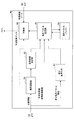
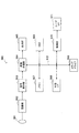
図19は、図18に示した画像復号化装置60の動き補償部90の詳細な構成の一例を示すブロック図である。図19を参照すると、動き補償部90は、境界認識部91、基準画素設定部92、差分符号化部93、動きベクトル設定部94、動きベクトルバッファ95及び予測部96を有する。
[3-2. Configuration example of motion compensation unit]
FIG. 19 is a block diagram illustrating an example of a detailed configuration of the
境界認識部91は、画像の符号化の際に画像内のブロックを分割した境界の傾きを認識する。かかる境界は、傾きを有する境界を含む複数の候補から選択される境界である。より具体的には、境界認識部91は、まず、可逆復号化部62から入力されるインター予測に関する情報に含まれる分割情報を取得する。分割情報は、例えば、画像符号化装置10において圧縮率の観点から最適であると判定された境界を特定する情報である。分割情報は、上述したように、例えば、矩形分割又はジオメトリ動き分割のいずれかを指定する分割モード情報、並びに境界の位置と傾きとを指定する境界パラメータ(例えば、上述した距離ρ及び傾き角θ)を含み得る。そして、境界認識部91は、取得した分割情報を参照し、各ブロックを分割した境界の傾きを認識する。
The
基準画素設定部92は、境界認識部91により認識される境界の傾きに応じて、ブロック内の各領域に基準画素位置を設定する。基準画素設定部92による基準画素位置設定処理は、図17に例示した画像符号化装置10の基準画素設定部43による処理と同様であってよい。そして、基準画素設定部92は、設定した基準画素位置を動きベクトル設定部94に通知する。
The reference
差分復号化部93は、可逆復号化部62から入力されるインター予測に関する情報に含まれる差分動きベクトル情報に基づいて、各領域について符号化の際に算出された差分動きベクトルを復号化する。そして、差分復号化部93は、差分動きベクトルを、動きベクトル設定部94へ出力する。
The
動きベクトル設定部94は、基準画素設定部92により設定される基準画素位置に対応するブロック又は領域に設定された動きベクトルに基づいて、分割されたブロック内の各領域内の画素値の予測に使用すべき動きベクトルを設定する。より具体的には、動きベクトル設定部94は、まず、可逆復号化部62から入力されるインター予測に関する情報に含まれる予測式情報を取得する。予測式情報は、各領域と関連付けて取得され得る。予測式情報は、例えば、空間的相関を利用した予測式、時間的相関を利用した予測式、並びに空間的相関及び時間的相関の双方を利用した予測式のうち、符号化の際に選択された予測式を特定する。次に、動きベクトル設定部94は、基準画素設定部92により設定された基準画素位置に対応する、符号化対象の画像内又は参照画像内の符号化済みのブロック若しくは領域に設定された動きベクトルを、参照動きベクトルとして取得する。そして、動きベクトル設定部94は、予測式情報が特定する予測式に参照動きベクトルを代入し、予測動きベクトルを算出する。さらに、動きベクトル設定部94は、算出した予測動きベクトルに、差分復号化部93から入力される差分動きベクトルを加算して動きベクトルを算出する。動きベクトル設定部94は、このように算出される動きベクトルを、各領域に設定する。また、動きベクトル設定部94は、各領域に設定した動きベクトルを、動きベクトルバッファ95へ出力する。
The motion
動きベクトルバッファ95は、動きベクトル設定部94による動きベクトル設定処理において参照される動きベクトルを、記憶媒体を用いて一時的に記憶する。動きベクトルバッファ95において参照される動きベクトルとは、復号化済みの参照画像内のブロック又は領域に設定された動きベクトル、及び符号化対象の画像内の他のブロック又は領域に設定された動きベクトルを含み得る。
The
予測部96は、境界認識部91により認識される境界により分割されたブロック内の領域ごとに、動きベクトル設定部94により設定される動きベクトル及び参照画像情報、並びにフレームメモリ69から入力される参照画像データを用いて、予測画素値を生成する。そして、予測部93は、生成した予測画素値を含む予測画像データをセレクタ71へ出力する。
The
<4.一実施形態に係る復号化時の処理の流れ>
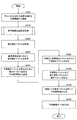
次に、図20を用いて、復号化時の処理の流れを説明する。図20は、本実施形態に係る画像復号化装置60の動き補償部90による動き補償処理の流れの一例を示すフローチャートである。
<4. Flow of Decoding Process According to One Embodiment>
Next, the flow of processing during decoding will be described with reference to FIG. FIG. 20 is a flowchart illustrating an example of the flow of motion compensation processing by the
図20を参照すると、まず、画像符号化装置60の境界認識部91は、画像の符号化の際に画像内のブロックを分割した境界の傾きを、可逆復号化部62から入力されるインター予測に関する情報に含まれる分割情報から認識する(ステップS200)。
Referring to FIG. 20, first, the
次に、基準画素設定部92は、境界認識部91により認識された境界の傾きに応じて、各領域に基準画素位置を設定する(ステップS210)。なお、基準画素設定部92による基準画素位置設定処理の流れは、図17に例示した画像符号化装置10の基準画素設定部43による処理と同様であってよい。
Next, the reference
次に、差分復号化部93は、可逆復号化部62から入力されるインター予測に関する情報に含まれる差分動きベクトル情報に基づいて、差分動きベクトルを取得する(ステップS220)。そして、差分復号化部93は、取得した差分動きベクトルを、動きベクトル設定部94へ出力する。
Next, the
次に、動きベクトル設定部94は、基準画素設定部92により設定された基準画素位置に対応するブロック又は領域に設定された動きベクトルである参照動きベクトルを、動きベクトルバッファ95から取得する(ステップS230)。
Next, the motion
次に、動きベクトル設定部94は、可逆復号化部62から入力されるインター予測に関する情報に含まれる予測式情報から、予測動きベクトルの算出のために使用すべき予測式を認識する(ステップS240)。
Next, the motion
次に、動きベクトル設定部94は、予測式情報から認識した予測式に参照動きベクトルを代入することにより、各領域についての予測動きベクトルを算出する(ステップS250)。
Next, the motion
次に、動きベクトル設定部94は、算出した予測動きベクトルに差分復号化部93から入力された差分動きベクトルを加算することにより、各領域についての動きベクトルを算出する(ステップS260)。動きベクトル設定部94は、このように領域ごとに動きベクトルを算出し、算出した動きベクトルを各領域に設定する。
Next, the motion
次に、予測部94は、動きベクトル設定部94により設定された動きベクトル及び参照画像情報、並びにフレームメモリ69から入力される参照画像データを用いて、予測画素値を生成する(ステップ270)。
Next, the
次に、予測部94は、生成した予測画素値を含む予測画像データをセレクタ71へ出力する(ステップS280)。
Next, the
<5.応用例>
上述した実施形態に係る画像符号化装置10及び画像復号化装置60は、衛星放送、ケーブルTVなどの有線放送、インターネット上での配信、及びセルラー通信による端末への配信などにおける送信機若しくは受信機、光ディスク、磁気ディスク及びフラッシュメモリなどの媒体に画像を記録する記録装置、又は、これら記憶媒体から画像を再生する再生装置などの様々な電子機器に応用され得る。以下、4つの応用例について説明する。
<5. Application example>
The
[5−1.第1の応用例]
図21は、上述した実施形態を適用したテレビジョン装置の概略的な構成の一例を示している。テレビジョン装置900は、アンテナ901、チューナ902、デマルチプレクサ903、デコーダ904、映像信号処理部905、表示部906、音声信号処理部907、スピーカ908、外部インタフェース909、制御部910、ユーザインタフェース911、及びバス912を備える。
[5-1. First application example]
FIG. 21 illustrates an example of a schematic configuration of a television device to which the above-described embodiment is applied. The
チューナ902は、アンテナ901を介して受信される放送信号から所望のチャンネルの信号を抽出し、抽出した信号を復調する。そして、チューナ902は、復調により得られた符号化ビットストリームをデマルチプレクサ903へ出力する。即ち、チューナ902は、画像が符号化されている符号化ストリームを受信する、テレビジョン装置900における伝送手段としての役割を有する。
The
デマルチプレクサ903は、符号化ビットストリームから視聴対象の番組の映像ストリーム及び音声ストリームを分離し、分離した各ストリームをデコーダ904へ出力する。また、デマルチプレクサ903は、符号化ビットストリームからEPG(Electronic Program Guide)などの補助的なデータを抽出し、抽出したデータを制御部910に供給する。なお、デマルチプレクサ903は、符号化ビットストリームがスクランブルされている場合には、デスクランブルを行ってもよい。
The
デコーダ904は、デマルチプレクサ903から入力される映像ストリーム及び音声ストリームを復号化する。そして、デコーダ904は、復号化処理により生成される映像データを映像信号処理部905へ出力する。また、デコーダ904は、復号化処理により生成される音声データを音声信号処理部907へ出力する。
The
映像信号処理部905は、デコーダ904から入力される映像データを再生し、表示部906に映像を表示させる。また、映像信号処理部905は、ネットワークを介して供給されるアプリケーション画面を表示部906に表示させてもよい。また、映像信号処理部905は、映像データについて、設定に応じて、例えばノイズ除去などの追加的な処理を行ってもよい。さらに、映像信号処理部905は、例えばメニュー、ボタン又はカーソルなどのGUI(Graphical User Interface)の画像を生成し、生成した画像を出力画像に重畳してもよい。
The video
表示部906は、映像信号処理部905から供給される駆動信号により駆動され、表示デバイス(例えば、液晶ディスプレイ、プラズマディスプレイ又はOLEDなど)の映像面上に映像又は画像を表示する。
The
音声信号処理部907は、デコーダ904から入力される音声データについてD/A変換及び増幅などの再生処理を行い、スピーカ908から音声を出力させる。また、音声信号処理部907は、音声データについてノイズ除去などの追加的な処理を行ってもよい。
The audio
外部インタフェース909は、テレビジョン装置900と外部機器又はネットワークとを接続するためのインタフェースである。例えば、外部インタフェース909を介して受信される映像ストリーム又は音声ストリームが、デコーダ904により復号化されてもよい。即ち、外部インタフェース909もまた、画像が符号化されている符号化ストリームを受信する、テレビジョン装置900における伝送手段としての役割を有する。
The
制御部910は、CPU(Central Processing Unit)などのプロセッサ、並びにRAM(Random Access Memory)及びROM(Read Only Memory)などのメモリを有する。メモリは、CPUにより実行されるプログラム、プログラムデータ、EPGデータ、及びネットワークを介して取得されるデータなどを記憶する。メモリにより記憶されるプログラムは、例えば、テレビジョン装置900の起動時にCPUにより読み込まれ、実行される。CPUは、プログラムを実行することにより、例えばユーザインタフェース911から入力される操作信号に応じて、テレビジョン装置900の動作を制御する。
The
ユーザインタフェース911は、制御部910と接続される。ユーザインタフェース911は、例えば、ユーザがテレビジョン装置900を操作するためのボタン及びスイッチ、並びに遠隔制御信号の受信部などを有する。ユーザインタフェース911は、これら構成要素を介してユーザによる操作を検出して操作信号を生成し、生成した操作信号を制御部910へ出力する。
The
バス912は、チューナ902、デマルチプレクサ903、デコーダ904、映像信号処理部905、音声信号処理部907、外部インタフェース909及び制御部910を相互に接続する。
The
このように構成されたテレビジョン装置900において、デコーダ904は、上述した実施形態に係る画像復号化装置60の機能を有する。それにより、テレビジョン装置900において、矩形以外の様々な形状をとり得る分割方式でブロックが分割される場合にも、適応的に基準画素位置を設定して動きベクトルを予測することにより、圧縮率を高めると共に、復号化後の画質を向上させることができる。
In the
[5−2.第2の応用例]
図22は、上述した実施形態を適用した携帯電話機の概略的な構成の一例を示している。携帯電話機920は、アンテナ921、通信部922、音声コーデック923、スピーカ924、マイクロホン925、カメラ部926、画像処理部927、多重分離部928、記録再生部929、表示部930、制御部931、操作部932、及びバス933を備える。
[5-2. Second application example]
FIG. 22 shows an example of a schematic configuration of a mobile phone to which the above-described embodiment is applied. A
アンテナ921は、通信部922に接続される。スピーカ924及びマイクロホン925は、音声コーデック923に接続される。操作部932は、制御部931に接続される。バス933は、通信部922、音声コーデック923、カメラ部926、画像処理部927、多重分離部928、記録再生部929、表示部930、及び制御部931を相互に接続する。
The
携帯電話機920は、音声通話モード、データ通信モード、撮影モード及びテレビ電話モードを含む様々な動作モードで、音声信号の送受信、電子メール又は画像データの送受信、画像の撮像、及びデータの記録などの動作を行う。
The
音声通話モードにおいて、マイクロホン925により生成されるアナログ音声信号は、音声コーデック923に供給される。音声コーデック923は、アナログ音声信号を音声データへ変換し、変換された音声データをA/D変換し圧縮する。そして、音声コーデック923は、圧縮後の音声データを通信部922へ出力する。通信部922は、音声データを符号化及び変調し、送信信号を生成する。そして、通信部922は、生成した送信信号をアンテナ921を介して基地局(図示せず)へ送信する。また、通信部922は、アンテナ921を介して受信される無線信号を増幅し及び周波数変換し、受信信号を取得する。そして、通信部922は、受信信号を復調及び復号化して音声データを生成し、生成した音声データを音声コーデック923へ出力する。音声コーデック923は、音声データを伸張し及びD/A変換し、アナログ音声信号を生成する。そして、音声コーデック923は、生成した音声信号をスピーカ924に供給して音声を出力させる。
In the voice call mode, an analog voice signal generated by the
また、データ通信モードにおいて、例えば、制御部931は、操作部932を介するユーザによる操作に応じて、電子メールを構成する文字データを生成する。また、制御部931は、文字を表示部930に表示させる。また、制御部931は、操作部932を介するユーザからの送信指示に応じて電子メールデータを生成し、生成した電子メールデータを通信部922へ出力する。通信部922は、電子メールデータを符号化及び変調し、送信信号を生成する。そして、通信部922は、生成した送信信号をアンテナ921を介して基地局(図示せず)へ送信する。また、通信部922は、アンテナ921を介して受信される無線信号を増幅し及び周波数変換し、受信信号を取得する。そして、通信部922は、受信信号を復調及び復号化して電子メールデータを復元し、復元した電子メールデータを制御部931へ出力する。制御部931は、表示部930に電子メールの内容を表示させると共に、電子メールデータを記録再生部929の記憶媒体に記憶させる。
Further, in the data communication mode, for example, the
記録再生部929は、読み書き可能な任意の記憶媒体を有する。例えば、記憶媒体は、RAM又はフラッシュメモリなどの内蔵型の記憶媒体であってもよく、ハードディスク、磁気ディスク、光磁気ディスク、光ディスク、USBメモリ、又はメモリカードなどの外部装着型の記憶媒体であってもよい。
The recording / reproducing
また、撮影モードにおいて、例えば、カメラ部926は、被写体を撮像して画像データを生成し、生成した画像データを画像処理部927へ出力する。画像処理部927は、カメラ部926から入力される画像データを符号化し、符号化ストリームを記憶再生部929の記憶媒体に記憶させる。
In the shooting mode, for example, the
また、テレビ電話モードにおいて、例えば、多重分離部928は、画像処理部927により符号化された映像ストリームと、音声コーデック923から入力される音声ストリームとを多重化し、多重化したストリームを通信部922へ出力する。通信部922は、ストリームを符号化及び変調し、送信信号を生成する。そして、通信部922は、生成した送信信号をアンテナ921を介して基地局(図示せず)へ送信する。また、通信部922は、アンテナ921を介して受信される無線信号を増幅し及び周波数変換し、受信信号を取得する。これら送信信号及び受信信号には、符号化ビットストリームが含まれ得る。そして、通信部922は、受信信号を復調及び復号化してストリームを復元し、復元したストリームを多重分離部928へ出力する。多重分離部928は、入力されるストリームから映像ストリーム及び音声ストリームを分離し、映像ストリームを画像処理部927、音声ストリームを音声コーデック923へ出力する。画像処理部927は、映像ストリームを復号化し、映像データを生成する。映像データは、表示部930に供給され、表示部930により一連の画像が表示される。音声コーデック923は、音声ストリームを伸張し及びD/A変換し、アナログ音声信号を生成する。そして、音声コーデック923は、生成した音声信号をスピーカ924に供給して音声を出力させる。
Further, in the videophone mode, for example, the
このように構成された携帯電話機920において、画像処理部927は、上述した実施形態に係る画像符号化装置10及び画像復号化装置60の機能を有する。それにより、携帯電話機920において、矩形以外の様々な形状をとり得る分割方式でブロックが分割される場合にも、適応的に基準画素位置を設定して動きベクトルを予測することにより、圧縮率を高めると共に、復号化後の画質を向上させることができる。
In the
[5−3.第3の応用例]
図23は、上述した実施形態を適用した記録再生装置の概略的な構成の一例を示している。記録再生装置940は、例えば、受信した放送番組の音声データ及び映像データを符号化して記録媒体に記録する。また、記録再生装置940は、例えば、他の装置から取得される音声データ及び映像データを符号化して記録媒体に記録してもよい。また、記録再生装置940は、例えば、ユーザの指示に応じて、記録媒体に記録されているデータをモニタ及びスピーカ上で再生する。このとき、記録再生装置940は、音声データ及び映像データを復号化する。
[5-3. Third application example]
FIG. 23 shows an example of a schematic configuration of a recording / reproducing apparatus to which the above-described embodiment is applied. For example, the recording / reproducing
記録再生装置940は、チューナ941、外部インタフェース942、エンコーダ943、HDD(Hard Disk Drive)944、ディスクドライブ945、セレクタ946、デコーダ947、OSD(On-Screen Display)948、制御部949、及びユーザインタフェース950を備える。
The recording / reproducing
チューナ941は、アンテナ(図示せず)を介して受信される放送信号から所望のチャンネルの信号を抽出し、抽出した信号を復調する。そして、チューナ941は、復調により得られた符号化ビットストリームをセレクタ946へ出力する。即ち、チューナ941は、記録再生装置940における伝送手段としての役割を有する。
The
外部インタフェース942は、記録再生装置940と外部機器又はネットワークとを接続するためのインタフェースである。外部インタフェース942は、例えば、IEEE1394インタフェース、ネットワークインタフェース、USBインタフェース、又はフラッシュメモリインタフェースなどであってよい。例えば、外部インタフェース942を介して受信される映像データ及び音声データは、エンコーダ943へ入力される。即ち、外部インタフェース942は、記録再生装置940における伝送手段としての役割を有する。
The
エンコーダ943は、外部インタフェース942から入力される映像データ及び音声データが符号化されていない場合に、映像データ及び音声データを符号化する。そして、エンコーダ943は、符号化ビットストリームをセレクタ946へ出力する。
The
HDD944は、映像及び音声などのコンテンツデータが圧縮された符号化ビットストリーム、各種プログラム及びその他のデータを内部のハードディスクに記録する。また、HDD944は、映像及び音声の再生時に、これらデータをハードディスクから読み出す。
The
ディスクドライブ945は、装着されている記録媒体へのデータの記録及び読み出しを行う。ディスクドライブ945に装着される記録媒体は、例えばDVDディスク(DVD−Video、DVD−RAM、DVD−R、DVD−RW、DVD+R、DVD+RW等)又はBlu−ray(登録商標)ディスクなどであってよい。
The
セレクタ946は、映像及び音声の記録時には、チューナ941又はエンコーダ943から入力される符号化ビットストリームを選択し、選択した符号化ビットストリームをHDD944又はディスクドライブ945へ出力する。また、セレクタ946は、映像及び音声の再生時には、HDD944又はディスクドライブ945から入力される符号化ビットストリームをデコーダ947へ出力する。
The
デコーダ947は、符号化ビットストリームを復号化し、映像データ及び音声データを生成する。そして、デコーダ947は、生成した映像データをOSD948へ出力する。また、デコーダ904は、生成した音声データを外部のスピーカへ出力する。
The
OSD948は、デコーダ947から入力される映像データを再生し、映像を表示する。また、OSD948は、表示する映像に、例えばメニュー、ボタン又はカーソルなどのGUIの画像を重畳してもよい。
The
制御部949は、CPUなどのプロセッサ、並びにRAM及びROMなどのメモリを有する。メモリは、CPUにより実行されるプログラム、及びプログラムデータなどを記憶する。メモリにより記憶されるプログラムは、例えば、記録再生装置940の起動時にCPUにより読み込まれ、実行される。CPUは、プログラムを実行することにより、例えばユーザインタフェース950から入力される操作信号に応じて、記録再生装置940の動作を制御する。
The
ユーザインタフェース950は、制御部949と接続される。ユーザインタフェース950は、例えば、ユーザが記録再生装置940を操作するためのボタン及びスイッチ、並びに遠隔制御信号の受信部などを有する。ユーザインタフェース950は、これら構成要素を介してユーザによる操作を検出して操作信号を生成し、生成した操作信号を制御部949へ出力する。
The
このように構成された記録再生装置940において、エンコーダ943は、上述した実施形態に係る画像符号化装置10の機能を有する。また、デコーダ947は、上述した実施形態に係る画像復号化装置60の機能を有する。それにより、記録再生装置940において、矩形以外の様々な形状をとり得る分割方式でブロックが分割される場合にも、適応的に基準画素位置を設定して動きベクトルを予測することにより、圧縮率を高めると共に、復号化後の画質を向上させることができる。
In the recording / reproducing
[5−4.第4の応用例]
図24は、上述した実施形態を適用した撮像装置の概略的な構成の一例を示している。撮像装置960は、被写体を撮像して画像を生成し、画像データを符号化して記録媒体に記録する。
[5-4. Fourth application example]
FIG. 24 illustrates an example of a schematic configuration of an imaging apparatus to which the above-described embodiment is applied. The
撮像装置960は、光学ブロック961、撮像部962、信号処理部963、画像処理部964、表示部965、外部インタフェース966、メモリ967、メディアドライブ968、OSD969、制御部970、ユーザインタフェース971、及びバス972を備える。
The
光学ブロック961は、撮像部962に接続される。撮像部962は、信号処理部963に接続される。表示部965は、画像処理部964に接続される。ユーザインタフェース971は、制御部970に接続される。バス972は、画像処理部964、外部インタフェース966、メモリ967、メディアドライブ968、OSD969、及び制御部970を相互に接続する。
The
光学ブロック961は、フォーカスレンズ及び絞り機構などを有する。光学ブロック961は、被写体の光学像を撮像部962の撮像面に結像させる。撮像部962は、CCD又はCMOSなどのイメージセンサを有し、撮像面に結像した光学像を光電変換によって電気信号としての画像信号に変換する。そして、撮像部962は、画像信号を信号処理部963へ出力する。
The
信号処理部963は、撮像部962から入力される画像信号に対してニー補正、ガンマ補正、色補正などの種々のカメラ信号処理を行う。信号処理部963は、カメラ信号処理後の画像データを画像処理部964へ出力する。
The
画像処理部964は、信号処理部963から入力される画像データを符号化し、符号化データを生成する。そして、画像処理部964は、生成した符号化データを外部インタフェース966又はメディアドライブ968へ出力する。また、画像処理部964は、外部インタフェース966又はメディアドライブ968から入力される符号化データを復号化し、画像データを生成する。そして、画像処理部964は、生成した画像データを表示部965へ出力する。また、画像処理部964は、信号処理部963から入力される画像データを表示部965へ出力して画像を表示させてもよい。また、画像処理部964は、OSD969から取得される表示用データを、表示部965へ出力する画像に重畳してもよい。
The
OSD969は、例えばメニュー、ボタン又はカーソルなどのGUIの画像を生成して、生成した画像を画像処理部964へ出力する。
The
外部インタフェース966は、例えばUSB入出力端子として構成される。外部インタフェース966は、例えば、画像の印刷時に、撮像装置960とプリンタとを接続する。また、外部インタフェース966には、必要に応じてドライブが接続される。ドライブには、例えば、磁気ディスク又は光ディスクなどのリムーバブルメディアが装着され、リムーバブルメディアから読み出されるプログラムが、撮像装置960にインストールされ得る。さらに、外部インタフェース966は、LAN又はインターネットなどのネットワークに接続されるネットワークインタフェースとして構成されてもよい。即ち、外部インタフェース966は、撮像装置960における伝送手段としての役割を有する。
The
メディアドライブ968に装着される記録媒体は、例えば、磁気ディスク、光磁気ディスク、光ディスク、又は半導体メモリなどの、読み書き可能な任意のリムーバブルメディアであってよい。また、メディアドライブ968に記録媒体が固定的に装着され、例えば、内蔵型ハードディスクドライブ又はSSD(Solid State Drive)のような非可搬性の記憶部が構成されてもよい。 The recording medium mounted on the media drive 968 may be any readable / writable removable medium such as a magnetic disk, a magneto-optical disk, an optical disk, or a semiconductor memory. Further, a recording medium may be fixedly attached to the media drive 968, and a non-portable storage unit such as a built-in hard disk drive or an SSD (Solid State Drive) may be configured.
制御部970は、CPUなどのプロセッサ、並びにRAM及びROMなどのメモリを有する。メモリは、CPUにより実行されるプログラム、及びプログラムデータなどを記憶する。メモリにより記憶されるプログラムは、例えば、撮像装置960の起動時にCPUにより読み込まれ、実行される。CPUは、プログラムを実行することにより、例えばユーザインタフェース971から入力される操作信号に応じて、撮像装置960の動作を制御する。
The
ユーザインタフェース971は、制御部970と接続される。ユーザインタフェース971は、例えば、ユーザが撮像装置960を操作するためのボタン及びスイッチなどを有する。ユーザインタフェース971は、これら構成要素を介してユーザによる操作を検出して操作信号を生成し、生成した操作信号を制御部970へ出力する。
The
このように構成された撮像装置960において、画像処理部964は、上述した実施形態に係る画像符号化装置10及び画像復号化装置60の機能を有する。それにより、撮像装置960において、矩形以外の様々な形状をとり得る分割方式でブロックが分割される場合にも、適応的に基準画素位置を設定して動きベクトルを予測することにより、圧縮率を高めると共に、復号化後の画質を向上させることができる。
In the
<6.まとめ>
ここまで、図1〜図26を用いて、本発明の一実施形態に係る画像符号化装置10及び画像復号化装置60について説明した。本実施形態によれば、傾きを有する境界を含む複数の候補から選択される境界によりブロックが分割され得る画像符号化方式において、画像の符号化の際には、上記境界の傾きに応じて各領域の基準画素位置が適応的に設定され、その基準画素位置に対応するブロック又は領域に設定された動きベクトルに基づいて、各領域内の画素値の予測に使用すべき動きベクトルが予測される。それにより、動き補償の処理単位が矩形領域以外の様々な形状をとり得る場合にも、動きの空間的相関若しくは時間的相関又はその双方を利用して、動きベクトルを効果的に予測することができる。その結果、画像の圧縮率を高めることが可能であり、復号化後の画質も向上され得る。
<6. Summary>
So far, the
また、本実施形態によれば、境界がブロックの互いに対角に位置する第1のコーナー及び第2のコーナーの少なくとも一方に重なるか否かによって、設定される基準画素位置が変化する。一般的に、画像内に設定されるブロックの形状は矩形であるため、ブロックの分割により形成される各領域の基準画素位置を、このような基準によって適応的に設定することが可能である。 Further, according to the present embodiment, the set reference pixel position changes depending on whether or not the boundary overlaps at least one of the first corner and the second corner located diagonally to each other in the block. In general, since the shape of a block set in an image is a rectangle, the reference pixel position of each region formed by dividing the block can be adaptively set according to such a reference.
また、本実施形態によれば、適応的に設定された基準画素位置に対応する参照画像内のコロケーテッドなブロック又は領域を決定することができる。それにより、例えばジオメトリ動き分割のような分割方式においても、動きベクトルを予測する際に、空間的相関を利用する予測式のみならず、時間的相関を利用する予測式、又は空間的相関及び時間的相関の双方を利用する予測式を用いることが可能となる。また、これら予測式の間で最適な予測式をブロックごとに切り替えて使用することも可能となる。それにより、画像の圧縮率及び/又は画質のさらなる向上が期待され得る。 Further, according to the present embodiment, it is possible to determine a collocated block or region in the reference image corresponding to the adaptively set reference pixel position. Accordingly, even in a division method such as geometry motion division, for example, when predicting a motion vector, not only a prediction formula that uses spatial correlation but also a prediction formula that uses temporal correlation, or spatial correlation and temporal It is possible to use a prediction formula that uses both of the correlations. It is also possible to switch between these prediction formulas and use the optimum prediction formula for each block. Thereby, further improvement in the compression ratio and / or image quality of the image can be expected.
なお、本明細書では、イントラ予測に関する情報及びインター予測に関する情報が、符号化ストリームのヘッダに多重化されて、符号化側から復号化側へ伝送される例について主に説明した。しかしながら、これら情報を伝送する手法はかかる例に限定されない。例えば、これら情報は、符号化ビットストリームに多重化されることなく、符号化ビットストリームと関連付けられた別個のデータとして伝送され又は記録されてもよい。ここで、「関連付ける」という用語は、ビットストリームに含まれる画像(スライス若しくはブロックなど、画像の一部であってもよい)と当該画像に対応する情報とを復号化時にリンクさせ得るようにすることを意味する。即ち、情報は、画像(又はビットストリーム)とは別の伝送路上で伝送されてもよい。また、情報は、画像(又はビットストリーム)とは別の記録媒体(又は同一の記録媒体の別の記録エリア)に記録されてもよい。さらに、情報と画像(又はビットストリーム)とは、例えば、複数フレーム、1フレーム、又はフレーム内の一部分などの任意の単位で互いに関連付けられてよい。 In addition, in this specification, the example which the information regarding intra prediction and the information regarding inter prediction are multiplexed by the header of the encoding stream, and is transmitted from the encoding side to the decoding side was mainly demonstrated. However, the method for transmitting such information is not limited to such an example. For example, these pieces of information may be transmitted or recorded as separate data associated with the encoded bitstream without being multiplexed into the encoded bitstream. Here, the term “associate” enables an image (which may be a part of an image such as a slice or a block) included in the bitstream and information corresponding to the image to be linked at the time of decoding. Means that. That is, information may be transmitted on a transmission path different from that of the image (or bit stream). Information may be recorded on a recording medium (or another recording area of the same recording medium) different from the image (or bit stream). Furthermore, the information and the image (or bit stream) may be associated with each other in an arbitrary unit such as a plurality of frames, one frame, or a part of the frame.
以上、添付図面を参照しながら本発明の好適な実施形態について詳細に説明したが、本発明はかかる例に限定されない。本発明の属する技術の分野における通常の知識を有する者であれば、特許請求の範囲に記載された技術的思想の範疇内において、各種の変更例または修正例に想到し得ることは明らかであり、これらについても、当然に本発明の技術的範囲に属するものと了解される。 The preferred embodiments of the present invention have been described in detail above with reference to the accompanying drawings, but the present invention is not limited to such examples. It is obvious that a person having ordinary knowledge in the technical field to which the present invention pertains can come up with various changes or modifications within the scope of the technical idea described in the claims. Of course, it is understood that these also belong to the technical scope of the present invention.
10 画像符号化装置(画像処理装置)
41 分割部
43 基準画素設定部
45 動きベクトル予測部
46 選択部
60 画像復号化装置(画像処理装置)
91 境界認識部
92 基準画素設定部
94 動きベクトル設定部
10 Image encoding device (image processing device)
41
91
Claims (18)
前記境界の傾きに応じて変化する基準画素位置に対応するブロック又は領域に設定された動きベクトルに基づいて、前記分割部により分割されるブロック内の各領域内の画素値の予測に使用すべき動きベクトルを予測する動きベクトル予測部と、
を備える画像処理装置。 A division unit that divides a block set in an image into a plurality of regions by a boundary selected from a plurality of candidates including a boundary having an inclination;
Based on the motion vector set in the block or area corresponding to the reference pixel position that changes according to the inclination of the boundary, it should be used for prediction of the pixel value in each area in the block divided by the dividing unit A motion vector prediction unit for predicting a motion vector;
An image processing apparatus comprising:
前記基準画素設定部は、前記境界が前記第1のコーナー及び前記第2のコーナーに重ならない場合には、前記第1のコーナーが属する第1の領域の前記基準画素位置を、前記第1のコーナー上に設定する、
請求項3に記載の画像処理装置。 The first corner is the upper left corner of the block;
The reference pixel setting unit determines the reference pixel position of the first region to which the first corner belongs when the boundary does not overlap the first corner and the second corner. Set on the corner,
The image processing apparatus according to claim 3.
前記動きベクトル予測部による予測結果に基づいて、前記第1の予測式及び前記第2の予測式を含む複数の予測式の候補から最良の符号化効率を達成する予測式を選択する選択部、
をさらに備える、
請求項1に記載の画像処理装置。 The motion vector prediction unit predicts a motion vector using a first prediction formula based on a motion vector set in a block or region in a reference image corresponding to the reference pixel position, and is adjacent to the reference pixel position. Predicting a motion vector using a second prediction formula based on motion vectors set in other blocks or regions;
A selection unit that selects a prediction formula that achieves the best coding efficiency from a plurality of prediction formula candidates including the first prediction formula and the second prediction formula based on a prediction result by the motion vector prediction unit;
Further comprising
The image processing apparatus according to claim 1.
画像内に設定されるブロックを、傾きを有する境界を含む複数の候補から選択される境界により、複数の領域に分割するステップと、
前記境界の傾きに応じて変化する基準画素位置に対応するブロック又は領域に設定された動きベクトルに基づいて、分割されたブロック内の各領域内の画素値の予測に使用すべき動きベクトルを予測するステップと、
を含む画像処理方法。 In an image processing method for processing an image,
Dividing a block set in an image into a plurality of regions by a boundary selected from a plurality of candidates including a boundary having an inclination;
Based on the motion vector set in the block or region corresponding to the reference pixel position that changes according to the inclination of the boundary, the motion vector to be used for predicting the pixel value in each region in the divided block is predicted. And steps to
An image processing method including:
前記境界の傾きに応じて変化する基準画素位置に対応するブロック又は領域に設定された動きベクトルに基づいて、前記境界により分割されたブロック内の各領域内の画素値の予測に使用すべき動きベクトルを設定する動きベクトル設定部と、
を備える画像処理装置。 A boundary selected from a plurality of candidates including a boundary having an inclination, and a boundary recognition unit for recognizing the inclination of the boundary obtained by dividing a block in the image at the time of image encoding;
The motion to be used for predicting the pixel value in each region in the block divided by the boundary based on the motion vector set in the block or region corresponding to the reference pixel position that changes according to the inclination of the boundary A motion vector setting unit for setting a vector;
An image processing apparatus comprising:
前記基準画素設定部は、前記境界が前記第1のコーナー及び前記第2のコーナーに重ならない場合には、前記第1のコーナーが属する第1の領域の前記基準画素位置を、前記第1のコーナー上に設定する、
請求項12に記載の画像処理装置。 The first corner is the upper left corner of the block;
The reference pixel setting unit determines the reference pixel position of the first region to which the first corner belongs when the boundary does not overlap the first corner and the second corner. Set on the corner,
The image processing apparatus according to claim 12.
傾きを有する境界を含む複数の候補から選択される境界であって、画像の符号化の際に前記画像内に設定されたブロックを分割した前記境界の傾きを認識するステップと、
前記境界の傾きに応じて変化する基準画素位置に対応するブロック又は領域に設定された動きベクトルに基づいて、前記境界により分割されたブロック内の各領域内の画素値の予測に使用すべき動きベクトルを設定するステップと、
を含む画像処理方法。
In an image processing method for processing an image,
A boundary selected from a plurality of candidates including a boundary having an inclination, and recognizing the inclination of the boundary obtained by dividing a block set in the image at the time of image encoding;
The motion to be used for predicting the pixel value in each region in the block divided by the boundary based on the motion vector set in the block or region corresponding to the reference pixel position that changes according to the inclination of the boundary Setting a vector; and
An image processing method including:
Priority Applications (4)
| Application Number | Priority Date | Filing Date | Title |
|---|---|---|---|
| JP2010160457A JP2012023597A (en) | 2010-07-15 | 2010-07-15 | Image processing device and image processing method |
| PCT/JP2011/064046 WO2012008270A1 (en) | 2010-07-15 | 2011-06-20 | Image processing apparatus and image processing method |
| US13/808,726 US20130266070A1 (en) | 2010-07-15 | 2011-06-20 | Image processing device and image processing metho |
| CN2011800339354A CN103004198A (en) | 2010-07-15 | 2011-06-20 | Image processing apparatus and image processing method |
Applications Claiming Priority (1)
| Application Number | Priority Date | Filing Date | Title |
|---|---|---|---|
| JP2010160457A JP2012023597A (en) | 2010-07-15 | 2010-07-15 | Image processing device and image processing method |
Publications (1)
| Publication Number | Publication Date |
|---|---|
| JP2012023597A true JP2012023597A (en) | 2012-02-02 |
Family
ID=45469280
Family Applications (1)
| Application Number | Title | Priority Date | Filing Date |
|---|---|---|---|
| JP2010160457A Withdrawn JP2012023597A (en) | 2010-07-15 | 2010-07-15 | Image processing device and image processing method |
Country Status (4)
| Country | Link |
|---|---|
| US (1) | US20130266070A1 (en) |
| JP (1) | JP2012023597A (en) |
| CN (1) | CN103004198A (en) |
| WO (1) | WO2012008270A1 (en) |
Cited By (8)
| Publication number | Priority date | Publication date | Assignee | Title |
|---|---|---|---|---|
| CN105637869A (en) * | 2013-10-16 | 2016-06-01 | 华为技术有限公司 | A method for determining a corner video part of a partition of a video coding block |
| KR20180059367A (en) * | 2016-11-25 | 2018-06-04 | 주식회사 케이티 | Method and apparatus for processing a video signal |
| WO2019151284A1 (en) * | 2018-01-30 | 2019-08-08 | パナソニック インテレクチュアル プロパティ コーポレーション オブ アメリカ | Encoding device, decoding device, encoding method, and decoding method |
| WO2019151279A1 (en) * | 2018-01-30 | 2019-08-08 | パナソニック インテレクチュアル プロパティ コーポレーション オブ アメリカ | Encoding device, decoding device, encoding method, and decoding method |
| WO2019151280A1 (en) * | 2018-01-30 | 2019-08-08 | パナソニック インテレクチュアル プロパティ コーポレーション オブ アメリカ | Coding device, decoding device, coding method, and decoding method |
| JP2020532227A (en) * | 2017-08-22 | 2020-11-05 | パナソニック インテレクチュアル プロパティ コーポレーション オブ アメリカPanasonic Intellectual Property Corporation of America | Image coding device, image decoding device, image coding method, and image decoding method |
| JP2020532225A (en) * | 2017-08-22 | 2020-11-05 | パナソニック インテレクチュアル プロパティ コーポレーション オブ アメリカPanasonic Intellectual Property Corporation of America | Image coding device, image decoding device, image coding method, and image decoding method |
| JP2022545785A (en) * | 2019-08-26 | 2022-10-31 | ホアウェイ・テクノロジーズ・カンパニー・リミテッド | Method and apparatus for motion information storage |
Families Citing this family (28)
| Publication number | Priority date | Publication date | Assignee | Title |
|---|---|---|---|---|
| CN106105199B (en) * | 2014-03-05 | 2020-01-07 | Lg 电子株式会社 | Method and apparatus for encoding/decoding image based on polygon unit |
| EP4020991A1 (en) * | 2014-12-26 | 2022-06-29 | Sony Group Corporation | Image processing apparatus and image processing method |
| GB2550579A (en) * | 2016-05-23 | 2017-11-29 | Sony Corp | Image data encoding and decoding |
| KR102528387B1 (en) * | 2017-01-09 | 2023-05-03 | 에스케이텔레콤 주식회사 | Apparatus and Method for Video Encoding or Decoding |
| CN116233416A (en) * | 2017-01-16 | 2023-06-06 | 世宗大学校产学协力团 | Image coding/decoding method |
| CN110999306B (en) * | 2017-08-22 | 2022-09-16 | 松下电器(美国)知识产权公司 | Image encoder and image decoder |
| CN107633477B (en) * | 2017-10-20 | 2021-04-20 | 上海兆芯集成电路有限公司 | Image processing method and device |
| WO2019151297A1 (en) | 2018-01-30 | 2019-08-08 | パナソニック インテレクチュアル プロパティ コーポレーション オブ アメリカ | Encoding device, decoding device, encoding method, and decoding method |
| JP2021514162A (en) * | 2018-02-22 | 2021-06-03 | エルジー エレクトロニクス インコーポレイティド | Video decoding method and device by block division structure in video coding system |
| CN117834910A (en) * | 2018-07-02 | 2024-04-05 | 英迪股份有限公司 | Method for decoding video and method for encoding video |
| MX2021000265A (en) | 2018-07-17 | 2021-03-25 | Panasonic Ip Corp America | Motion vector prediction for video coding. |
| CN110891176B (en) | 2018-09-10 | 2023-01-13 | 华为技术有限公司 | Motion vector prediction method and device based on affine motion model |
| WO2020072494A1 (en) * | 2018-10-01 | 2020-04-09 | Op Solutions, Llc | Methods and systems of exponential partitioning |
| CN112997489B (en) | 2018-11-06 | 2024-02-06 | 北京字节跳动网络技术有限公司 | Side information signaling with inter prediction of geometric partitioning |
| EP3878172A4 (en) * | 2018-11-12 | 2022-08-24 | HFI Innovation Inc. | Method and apparatus of multi-hypothesis in video coding |
| WO2020103934A1 (en) * | 2018-11-22 | 2020-05-28 | Beijing Bytedance Network Technology Co., Ltd. | Construction method for inter prediction with geometry partition |
| DE102018220236A1 (en) * | 2018-11-26 | 2020-05-28 | Heidelberger Druckmaschinen Ag | Fast image rectification for image inspection |
| WO2020135465A1 (en) | 2018-12-28 | 2020-07-02 | Beijing Bytedance Network Technology Co., Ltd. | Modified history based motion prediction |
| CN113170166B (en) | 2018-12-30 | 2023-06-09 | 北京字节跳动网络技术有限公司 | Use of inter prediction with geometric partitioning in video processing |
| SG11202108101SA (en) * | 2019-01-28 | 2021-08-30 | Op Solutions Llc | Inter prediction in exponential partitioning |
| EP3915261A4 (en) * | 2019-01-31 | 2023-03-01 | HFI Innovation Inc. | Method and apparatus of combined inter and intra prediction for video coding |
| TWI737141B (en) | 2019-01-31 | 2021-08-21 | 聯發科技股份有限公司 | Method and apparatus of transform type assignment for intra sub-partition in video coding |
| KR20220024773A (en) * | 2019-06-24 | 2022-03-03 | 알리바바 그룹 홀딩 리미티드 | Method and device for storing motion field in video coding |
| WO2020263472A1 (en) * | 2019-06-24 | 2020-12-30 | Alibaba Group Holding Limited | Method and apparatus for motion vector refinement |
| US11190777B2 (en) * | 2019-06-30 | 2021-11-30 | Tencent America LLC | Method and apparatus for video coding |
| US11317090B2 (en) * | 2019-08-12 | 2022-04-26 | Tencent America LLC | Method and apparatus for video coding |
| US11284078B2 (en) | 2019-12-30 | 2022-03-22 | FG Innovation Company Limited | Device and method for coding video data |
| CN113473141A (en) * | 2020-03-31 | 2021-10-01 | Oppo广东移动通信有限公司 | Inter prediction method, encoder, decoder, and computer-readable storage medium |
Family Cites Families (8)
| Publication number | Priority date | Publication date | Assignee | Title |
|---|---|---|---|---|
| JP2500439B2 (en) * | 1993-05-14 | 1996-05-29 | 日本電気株式会社 | Predictive coding method for moving images |
| JPH09154138A (en) * | 1995-05-31 | 1997-06-10 | Toshiba Corp | Moving image coding/decoding device |
| EP0731614B1 (en) * | 1995-03-10 | 2002-02-06 | Kabushiki Kaisha Toshiba | Video coding/decoding apparatus |
| CN101409838B (en) * | 2001-09-14 | 2011-01-12 | 株式会社Ntt都科摩 | Coding method, decoding method, coding apparatus, decoding apparatus, and image processing system |
| WO2003026315A1 (en) * | 2001-09-14 | 2003-03-27 | Ntt Docomo, Inc. | Coding method, decoding method, coding apparatus, decoding apparatus, image processing system, coding program, and decoding program |
| BRPI0715507A2 (en) * | 2006-08-02 | 2013-06-18 | Thomson Licensinc S A | Methods and apparatus for adaptive geometric partitioning for video decoding |
| US8879632B2 (en) * | 2010-02-18 | 2014-11-04 | Qualcomm Incorporated | Fixed point implementation for geometric motion partitioning |
| PL2651128T3 (en) * | 2010-12-06 | 2019-01-31 | Sun Patent Trust | Image encoding method, image decoding method, image encoding device, and image decoding device |
-
2010
- 2010-07-15 JP JP2010160457A patent/JP2012023597A/en not_active Withdrawn
-
2011
- 2011-06-20 WO PCT/JP2011/064046 patent/WO2012008270A1/en active Application Filing
- 2011-06-20 US US13/808,726 patent/US20130266070A1/en not_active Abandoned
- 2011-06-20 CN CN2011800339354A patent/CN103004198A/en active Pending
Cited By (36)
| Publication number | Priority date | Publication date | Assignee | Title |
|---|---|---|---|---|
| JP2016533667A (en) * | 2013-10-16 | 2016-10-27 | 華為技術有限公司Huawei Technologies Co.,Ltd. | How to determine the corner video part of video coding block partition |
| CN105637869B (en) * | 2013-10-16 | 2020-09-04 | 华为技术有限公司 | Method for determining corner video portions of partitions of a video coding block |
| CN105637869A (en) * | 2013-10-16 | 2016-06-01 | 华为技术有限公司 | A method for determining a corner video part of a partition of a video coding block |
| KR20180059367A (en) * | 2016-11-25 | 2018-06-04 | 주식회사 케이티 | Method and apparatus for processing a video signal |
| US11968364B2 (en) | 2016-11-25 | 2024-04-23 | Kt Corporation | Method and apparatus for processing video signal |
| KR102559062B1 (en) | 2016-11-25 | 2023-07-24 | 주식회사 케이티 | Method and apparatus for processing a video signal |
| JP7102508B2 (en) | 2017-08-22 | 2022-07-19 | パナソニック インテレクチュアル プロパティ コーポレーション オブ アメリカ | Image coding device |
| JP7446393B2 (en) | 2017-08-22 | 2024-03-08 | パナソニック インテレクチュアル プロパティ コーポレーション オブ アメリカ | Image encoding device, image decoding device, and bitstream generation device |
| JP2020532227A (en) * | 2017-08-22 | 2020-11-05 | パナソニック インテレクチュアル プロパティ コーポレーション オブ アメリカPanasonic Intellectual Property Corporation of America | Image coding device, image decoding device, image coding method, and image decoding method |
| JP2020532225A (en) * | 2017-08-22 | 2020-11-05 | パナソニック インテレクチュアル プロパティ コーポレーション オブ アメリカPanasonic Intellectual Property Corporation of America | Image coding device, image decoding device, image coding method, and image decoding method |
| JP7179832B2 (en) | 2017-08-22 | 2022-11-29 | パナソニック インテレクチュアル プロパティ コーポレーション オブ アメリカ | image coding device |
| US11558635B2 (en) | 2018-01-30 | 2023-01-17 | Panasonic Intellectual Property Corporation Of America | Encoder, decoder, encoding method, and decoding method |
| US11889105B2 (en) | 2018-01-30 | 2024-01-30 | Panasonic Intellectual Property Corporation Of America | Encoder, decoder, encoding method, and decoding method |
| US11146812B2 (en) | 2018-01-30 | 2021-10-12 | Panasonic Intellectual Property Corporation Of America | Encoder, decoder, encoding method, and decoding method |
| US11350092B2 (en) | 2018-01-30 | 2022-05-31 | Panasonic Intellectual Property Corporation Of America | Encoder, decoder, encoding method, and decoding method |
| JPWO2019151284A1 (en) * | 2018-01-30 | 2021-01-28 | パナソニック インテレクチュアル プロパティ コーポレーション オブ アメリカPanasonic Intellectual Property Corporation of America | Encoding device, decoding device, coding method and decoding method |
| WO2019151284A1 (en) * | 2018-01-30 | 2019-08-08 | パナソニック インテレクチュアル プロパティ コーポレーション オブ アメリカ | Encoding device, decoding device, encoding method, and decoding method |
| JPWO2019151280A1 (en) * | 2018-01-30 | 2021-01-14 | パナソニック インテレクチュアル プロパティ コーポレーション オブ アメリカPanasonic Intellectual Property Corporation of America | Encoding device, decoding device, coding method and decoding method |
| CN111989923A (en) * | 2018-01-30 | 2020-11-24 | 松下电器(美国)知识产权公司 | Encoding device, decoding device, encoding method, and decoding method |
| WO2019151280A1 (en) * | 2018-01-30 | 2019-08-08 | パナソニック インテレクチュアル プロパティ コーポレーション オブ アメリカ | Coding device, decoding device, coding method, and decoding method |
| JP7315480B2 (en) | 2018-01-30 | 2023-07-26 | パナソニック インテレクチュアル プロパティ コーポレーション オブ アメリカ | Encoding device, decoding device, encoding method and decoding method |
| US11956467B2 (en) | 2018-01-30 | 2024-04-09 | Panasonic Intellectual Property Corporation Of America | Encoder, decoder, encoding method, and decoding method |
| JP7401309B2 (en) | 2018-01-30 | 2023-12-19 | パナソニック インテレクチュアル プロパティ コーポレーション オブ アメリカ | Encoding device, decoding device, encoding method, and decoding method |
| US11882279B2 (en) | 2018-01-30 | 2024-01-23 | Panasonic Intellectual Property Corporation Of America | Encoder, decoder, encoding method, and decoding method |
| US11044491B2 (en) | 2018-01-30 | 2021-06-22 | Panasonic Intellectual Property Corporation Of America | Encoder, decoder, encoding method, and decoding method |
| US11889103B2 (en) | 2018-01-30 | 2024-01-30 | Panasonic Intellectual Property Corporation Of America | Encoder, decoder, encoding method, and decoding method |
| US11889104B2 (en) | 2018-01-30 | 2024-01-30 | Panasonic Intellectual Property Corporation Of America | Encoder, decoder, encoding method, and decoding method |
| US11895298B2 (en) | 2018-01-30 | 2024-02-06 | Panasonic Intellectual Property Corporation Of America | Encoder, decoder, encoding method, and decoding method |
| US11895323B2 (en) | 2018-01-30 | 2024-02-06 | Panasonic Intellectual Property Corporation Of America | Encoder, decoder, encoding method, and decoding method |
| US11895322B2 (en) | 2018-01-30 | 2024-02-06 | Panasonic Intellectual Property Corporation Of America | Encoder, decoder, encoding method, and decoding method |
| US11909968B2 (en) | 2018-01-30 | 2024-02-20 | Panasonic Intellectual Property Corporation Of America | Encoder, decoder, encoding method, and decoding method |
| US11917150B2 (en) | 2018-01-30 | 2024-02-27 | Panasonic Intellectual Property Corporation Of America | Encoder, decoder, encoding method, and decoding method |
| US11924423B2 (en) | 2018-01-30 | 2024-03-05 | Panasonic Intellectual Property Corporation Of America | Encoder, decoder, encoding method, and decoding method |
| WO2019151279A1 (en) * | 2018-01-30 | 2019-08-08 | パナソニック インテレクチュアル プロパティ コーポレーション オブ アメリカ | Encoding device, decoding device, encoding method, and decoding method |
| JP7385004B2 (en) | 2019-08-26 | 2023-11-21 | ホアウェイ・テクノロジーズ・カンパニー・リミテッド | Method and apparatus for motion information storage |
| JP2022545785A (en) * | 2019-08-26 | 2022-10-31 | ホアウェイ・テクノロジーズ・カンパニー・リミテッド | Method and apparatus for motion information storage |
Also Published As
| Publication number | Publication date |
|---|---|
| US20130266070A1 (en) | 2013-10-10 |
| CN103004198A (en) | 2013-03-27 |
| WO2012008270A1 (en) | 2012-01-19 |
Similar Documents
| Publication | Publication Date | Title |
|---|---|---|
| WO2012008270A1 (en) | Image processing apparatus and image processing method | |
| US10623761B2 (en) | Image processing apparatus and image processing method | |
| JP6057140B2 (en) | Image processing apparatus and method, program, and recording medium | |
| JP6274103B2 (en) | Image processing apparatus and method | |
| JP2016197886A (en) | Image processing device, method, and program | |
| US20120027094A1 (en) | Image processing device and method | |
| US20130259129A1 (en) | Image processing device and method | |
| US20120057632A1 (en) | Image processing device and method | |
| JP2013141187A (en) | Image processing apparatus and image processing method | |
| KR20140109875A (en) | Image processing device and method | |
| KR20120058521A (en) | Image processing device and method | |
| WO2012043165A1 (en) | Image processing device and image processing method | |
| WO2013164922A1 (en) | Image processing device and image processing method | |
| US20120288006A1 (en) | Apparatus and method for image processing | |
| US10873758B2 (en) | Image processing device and method | |
| JP2013098933A (en) | Image processing device and method | |
| WO2014038330A1 (en) | Image processing device and image processing method | |
| WO2013157308A1 (en) | Image processing device and image processing method | |
| JPWO2013108688A1 (en) | Image processing apparatus and method | |
| US20150304678A1 (en) | Image processing device and method | |
| US20130107968A1 (en) | Image Processing Device and Method | |
| JP6268556B2 (en) | Image processing apparatus and method, program, and recording medium | |
| WO2011125625A1 (en) | Image processing device and method | |
| US20130259134A1 (en) | Image decoding device and motion vector decoding method, and image encoding device and motion vector encoding method | |
| JP6048564B2 (en) | Image processing apparatus and image processing method |
Legal Events
| Date | Code | Title | Description |
|---|---|---|---|
| A300 | Application deemed to be withdrawn because no request for examination was validly filed |
Free format text: JAPANESE INTERMEDIATE CODE: A300 Effective date: 20131001 |