JP2012014149A - Image processor and control method of the same - Google Patents
Image processor and control method of the same Download PDFInfo
- Publication number
- JP2012014149A JP2012014149A JP2011095364A JP2011095364A JP2012014149A JP 2012014149 A JP2012014149 A JP 2012014149A JP 2011095364 A JP2011095364 A JP 2011095364A JP 2011095364 A JP2011095364 A JP 2011095364A JP 2012014149 A JP2012014149 A JP 2012014149A
- Authority
- JP
- Japan
- Prior art keywords
- image
- unit
- test pattern
- pattern
- amplitude
- Prior art date
- Legal status (The legal status is an assumption and is not a legal conclusion. Google has not performed a legal analysis and makes no representation as to the accuracy of the status listed.)
- Pending
Links
Images


Classifications
-
- H—ELECTRICITY
- H04—ELECTRIC COMMUNICATION TECHNIQUE
- H04N—PICTORIAL COMMUNICATION, e.g. TELEVISION
- H04N1/00—Scanning, transmission or reproduction of documents or the like, e.g. facsimile transmission; Details thereof
- H04N1/40—Picture signal circuits
- H04N1/409—Edge or detail enhancement; Noise or error suppression
Landscapes
- Engineering & Computer Science (AREA)
- Multimedia (AREA)
- Signal Processing (AREA)
- Control Or Security For Electrophotography (AREA)
- Color, Gradation (AREA)
- Laser Beam Printer (AREA)
- Facsimile Image Signal Circuits (AREA)
Abstract
Description
本発明は濃度ムラを簡易に抑制するために用いて好適な技術に関する。 The present invention relates to a technique suitable for use in easily suppressing density unevenness.
従来における画像処理装置の画像形成部として、感光体ドラム、帯電装置、露光装置、現像装置、および転写装置等の複数のモジュールを備えたものが知られている。このような画像形成部では、回転する感光体ドラムを、帯電装置によって一様に帯電する。次いで、帯電後の感光体ドラム表面を露光装置によって選択的に露光し、感光体ドラム上に静電潜像を形成する。そして、感光体ドラム上に形成された静電潜像を現像装置により現像して可視像化した後、得られたトナー像を転写装置によって記録材に転写する。 As an image forming unit of a conventional image processing apparatus, one having a plurality of modules such as a photosensitive drum, a charging device, an exposure device, a developing device, and a transfer device is known. In such an image forming unit, the rotating photosensitive drum is uniformly charged by a charging device. Next, the charged photosensitive drum surface is selectively exposed by an exposure device to form an electrostatic latent image on the photosensitive drum. The electrostatic latent image formed on the photosensitive drum is developed by a developing device to be a visible image, and the obtained toner image is transferred to a recording material by a transfer device.
このような画像形成部では、感光体ドラムの回転方向すなわち副走査方向に、濃度ムラが生じることがある。モジュールの多くは、ドラム、ローラ、スリーブ、スクリュ等の回転体を有しており、これらが回転することにより動作している。各モジュールの回転動力となるモータは誤差を有しており、シャフトの回転角によって回転速度が異なる。このため、例えば、感光体ドラムは駆動モータの回転に応じて周期的に回転速度変動を起こし、これに伴い面積あたりの露光量の粗密が発生し、出力画像に周期的な濃度ムラを引き起こす。モータ駆動を回転体に伝えるギアの精度も同様に濃度ムラの要因となる。 In such an image forming unit, density unevenness may occur in the rotation direction of the photosensitive drum, that is, in the sub-scanning direction. Many of the modules have rotating bodies such as a drum, a roller, a sleeve, and a screw, and operate by rotating them. The motor that is the rotational power of each module has an error, and the rotational speed varies depending on the rotational angle of the shaft. For this reason, for example, the photosensitive drum periodically varies in rotation speed in accordance with the rotation of the drive motor, and accordingly, the exposure amount per area varies in density, causing periodic density unevenness in the output image. The accuracy of the gear that transmits the motor drive to the rotating body is also a factor of density unevenness.
また、回転体の軸の偏芯がある場合、例えば感光体ドラムに偏芯があった場合は、現像装置との距離が周期的に変動するため、これも距離に応じた現像効率の変化により濃度ムラが発生する。さらに、帯電や現像で用いる交流電圧に関しても、同様に現像量が変化するため、周期的濃度ムラとなる。このように、画像形成部を構成する各モジュールは周期的濃度ムラの発生要因となっている。 In addition, when the shaft of the rotating body is eccentric, for example, when the photosensitive drum is eccentric, the distance from the developing device fluctuates periodically, which is also caused by the change in development efficiency according to the distance. Density unevenness occurs. Furthermore, regarding the AC voltage used for charging and development, the development amount changes in the same manner, resulting in periodic density unevenness. As described above, each module constituting the image forming unit is a cause of periodic density unevenness.
また、各モジュールが有する周期性は、複数重なることで異なる周波数の干渉を起こし、これも周期的濃度ムラの要因となる。このような問題を解決するため、発生した濃度変動を濃度検出装置で検出し、露光装置の点灯時間を調整することで補正する技術が提案されている(特許文献1参照)。 In addition, the periodicity of each module causes interference at different frequencies due to the overlap, which also causes periodic density unevenness. In order to solve such a problem, a technique has been proposed in which the generated density fluctuation is detected by a density detection device and corrected by adjusting the lighting time of the exposure device (see Patent Document 1).
また、画像形成部に搭載されたスキャナで最終画像(テスト画像)を読み取って濃度分布を検出し、この濃度分布に基づいて周期的濃度ムラを補正することが提案されている。例えば、テスト画像をスキャナで読み取って主走査方向又は副走査方向の濃度データを検出し、これに基づいて作成した補正データにより画素データを補正する方法が提供されている(特許文献2参照)。これらの技術はどれも、発生する濃度特性の逆特性の補正を施すことで、周期的濃度ムラを低減するようにしている。 Further, it has been proposed to read a final image (test image) with a scanner mounted on an image forming unit to detect a density distribution, and to correct periodic density unevenness based on the density distribution. For example, a method is provided in which density data in the main scanning direction or sub-scanning direction is detected by reading a test image with a scanner, and pixel data is corrected using correction data created based on the density data (see Patent Document 2). In any of these techniques, periodic density unevenness is reduced by correcting a reverse characteristic of the generated density characteristic.
特許文献1に記載の技術では、周期、波形、位相、振幅のすべての情報を測定し、補正パラメータを決定する必要があるため、画像形成部の有する周期より十分に小さい単位で、画像の濃度を検出する必要がある。このため、高い精度の分解能や応答性を備えた濃度検出装置が必要となる。また、各モジュールで発生する複数の周期性の位相を揃えるため、各モジュールの外径を同一もしくは整数倍に揃えるなどの設計上の制約が必要となり、設計の自由度が失われるという課題がある。 In the technique described in Patent Document 1, since it is necessary to measure all information of the period, waveform, phase, and amplitude and determine the correction parameter, the density of the image is in units sufficiently smaller than the period of the image forming unit. Need to be detected. For this reason, the density | concentration detection apparatus provided with the high precision resolution and responsiveness is needed. In addition, in order to align a plurality of periodic phases generated in each module, design restrictions such as aligning the outer diameter of each module to the same or an integral multiple are required, and there is a problem that the degree of freedom in design is lost. .
また、特許文献2記載の技術に関しても、同様に、周期、波形、位相、振幅のすべての情報を測定し、補正パラメータを決定する必要があり、スキャナ等の大掛かりな装置を必要とする。また、転写体もしくは紙面上に形成される画像の単位で補正を行う必要があるために各モジュールの回転周期が、画像に対して整数分の1倍である必要がある。仮に、各モジュールの回転周期が整数分の1倍でない場合には、出力するごとにモジュールの位相がずれるため、スキャナから算出した補正量を用いても、正しい補正がされないという問題がある。 Similarly, with respect to the technique described in Patent Document 2, it is necessary to measure all information on the period, waveform, phase, and amplitude to determine the correction parameter, and a large-scale device such as a scanner is required. In addition, since it is necessary to perform correction in units of images formed on a transfer body or paper, the rotation period of each module needs to be 1 / integer of the image. If the rotation period of each module is not an integral number of one, the phase of the module is shifted each time it is output, so that there is a problem that correct correction is not performed even if the correction amount calculated from the scanner is used.
また、どちらの技術も、測定データを記憶するためのメモリ、測定タイミングと補正タイミングとを同期させるための同期システム等が必要となるので、装置構成が大掛かりとなり、低コスト化を実現する妨げとなっている。
本発明前述の問題点に鑑み、モジュールに起因する濃度ムラを簡易に抑制できるようにすることを目的とする。
In addition, both technologies require a memory for storing measurement data, a synchronization system for synchronizing the measurement timing and the correction timing, etc., which increases the apparatus configuration and hinders cost reduction. It has become.
An object of the present invention is to make it possible to easily suppress density unevenness caused by a module in view of the above-described problems.
本発明の画像処理装置は、画像形成部の固有の周期を記憶媒体に記憶する記憶手段と、前記記憶媒体に記憶されている装置固有の周期を持ち、且つその他のパラメータの異なる複数の画像パターンを生成するパターン生成手段と、前記パターン生成手段により生成された複数の画像パターンの中から一つのテストパターンを選択する選択手段と、前記選択手段により選択されたテストパターンに応じて画像の補正を行う画像補正手段とを有することを特徴とする。 An image processing apparatus according to the present invention includes a storage unit that stores a unique period of an image forming unit in a storage medium, and a plurality of image patterns that have a period unique to the apparatus stored in the storage medium and have different parameters. A pattern generation means for generating the image, a selection means for selecting one test pattern from among the plurality of image patterns generated by the pattern generation means, and an image correction according to the test pattern selected by the selection means. And an image correcting unit for performing the correction.
本発明によれば、簡単な構成により、モジュールの周期性に起因する濃度ムラを抑制することができる。 According to the present invention, density unevenness caused by the periodicity of the module can be suppressed with a simple configuration.
画像処理装置の画像形成部で発生する濃度ムラの変動周期は、回転体の周期や交流電圧などに依存しており、多くの場合、設計段階で既知である。また同様に、1周期の中で濃度がどのように変動しているかを示す波形については、要因となるモジュール毎に形状がほぼ決まっており、再現性も高いため予め用意しておくことが可能である。さらに、実際の画像形成部で発生する変動周期は、アナログ的であるものが多いため、ほぼ正弦波で近似することが可能である。また、濃度ムラの波形と補正の波形が異なる場合、例えば、三角波で発生する濃度ムラを逆位相の正弦波で補正する場合、高調波が発生するものの、濃度ムラを多少は目立たなくすることができる。 The fluctuation period of density unevenness generated in the image forming unit of the image processing apparatus depends on the period of the rotating body, the AC voltage, and the like, and is often known at the design stage. Similarly, the waveform showing how the concentration fluctuates in one cycle is almost fixed for each factor module, and can be prepared in advance because of its high reproducibility. It is. Further, since the fluctuation cycle generated in the actual image forming unit is often analog, it can be approximated by a sine wave. In addition, if the waveform of density unevenness is different from the waveform of correction, for example, when correcting density unevenness generated by a triangular wave with a sine wave having an opposite phase, harmonics may be generated, but the density unevenness may be somewhat inconspicuous. it can.
また、この他に濃度ムラの補正に必要な特徴量として、位相、振幅が挙げられる。ここで、振幅に関しては、誤差が発生しても実際の振幅の0〜2倍の範囲にあれば、補正前の濃度ムラより悪化することがないため、過剰な精度は要求されない。一方、位相に関しては、単純な波の足し合わせの問題から、その変動周期の1/6以上ずれた状態で逆特性の補正を施すと、補正前より濃度ムラが悪化してしまう。このことから、実際の補正には、濃度ムラの位相と振幅をどのような手順で求めるかが重要となる。 In addition, phase and amplitude can be cited as feature quantities necessary for correcting density unevenness. Here, regarding the amplitude, even if an error occurs, if it is in the range of 0 to 2 times the actual amplitude, it will not be worse than the density unevenness before correction, so that excessive accuracy is not required. On the other hand, regarding the phase, due to the problem of simple addition of waves, if the reverse characteristic is corrected in a state of being shifted by 1/6 or more of the fluctuation period, the density unevenness becomes worse than before the correction. For this reason, in actual correction, it is important to determine in what procedure the phase and amplitude of density unevenness are obtained.
(第1の実施形態)
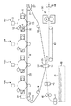
図1は、第1の実施形態に係る画像形成部の概要を示す図である。本実施形態の画像形成部は、例えば電子写真方式にて各色成分トナー像が形成される複数(図1の例では四つ)の画像形成ユニット10(具体的には10Y、10M、10C、10K)を備える。また、この画像形成部は、それぞれの画像形成ユニット10により形成された各色成分トナー像が順次転写(一次転写)される中間転写ベルト20を具備する。さらに、この画像形成部は、中間転写ベルト20に転写されたトナー画像を用紙Pに一括転写(二次転写)させる二次転写装置30を備える。さらにまた、この画像形成部は、二次転写されたトナー画像を用紙P上に定着させる定着装置50を有している。
(First embodiment)
FIG. 1 is a diagram illustrating an overview of an image forming unit according to the first embodiment. The image forming unit according to the present exemplary embodiment includes a plurality of (four in the example of FIG. 1) image forming units 10 (specifically, 10Y, 10M, 10C, 10K) on which each color component toner image is formed by, for example, electrophotography. ). In addition, the image forming unit includes an
それぞれの画像形成ユニット10(10Y、10M、10C、10K)は、使用されるトナーの色を除き、同じ構成を有している。そこで、イエローの画像形成ユニット10Yを例に説明を行う。イエローの画像形成ユニット10Yは、図示しない感光層を有し、矢印A方向に回転可能に配設される感光体ドラム11を具備している。この感光体ドラム11の周囲には、帯電装置12、露光部13、現像装置14、一次転写装置15、およびクリーナ16が配設される。これらのうち、帯電装置12は、感光体ドラム11を所定の電位に帯電する。
Each of the image forming units 10 (10Y, 10M, 10C, 10K) has the same configuration except for the color of the toner used. Therefore, the yellow
露光部13は、帯電装置12によって所定の負の電位に帯電された感光体ドラム11に、レーザ光によって静電潜像を書き込む。現像装置14は、対応する色成分トナー(画像形成ユニット10Yではイエローのトナー)を収容し、このトナーによって感光体ドラム11上の静電潜像を現像する。一次転写装置15は、感光体ドラム11上に形成されたトナー像を中間転写ベルト20に一次転写する。クリーナ16は、一次転写後の感光体ドラム11上の残留物(トナー等)を除去する。
The
中間転写ベルト20は、複数(本実施の形態では六つ)の支持ロールに回動可能に張架支持される。これらの支持ロールのうち、駆動ロール21は、中間転写ベルト20を張架するとともに中間転写ベルト20を駆動して回動させる。また、従動ロール22、23、26は、中間転写ベルト20を張架するとともに駆動ロール21によって駆動される中間転写ベルト20に従動して回転する。
The
補正ロール24は、中間転写ベルト20を張架するとともに中間転写ベルト20の搬送方向に略直交する方向の蛇行を規制するステアリングロール(軸方向一端部を支点として傾動自在に配設される)として機能する。さらに、バックアップロール25は、中間転写ベルト20を張架するとともに後述する二次転写装置30の構成部材として機能する。また、中間転写ベルト20を挟んで駆動ロール21と対向する部位には、二次転写後の中間転写ベルト20上の残留物(トナー等)を除去するベルトクリーナ27が配設されている。
The
二次転写装置30は、中間転写ベルト20のトナー像担持面側に圧接配置される二次転写ロール31と、中間転写ベルト20の裏面側に配置されて二次転写ロール31の対向電極をなすバックアップロール25とを備えている。このバックアップロール25には、トナーの帯電極性と同極性の二次転写バイアスを印加する給電ロール32が当接配置されている。一方、二次転写ロール31は接地されている。
The secondary transfer device 30 includes a
また、用紙搬送系は、用紙トレイ40、搬送ロール41、レジストレーションロール42、搬送ベルト43、および排出ロール44を備える。用紙搬送系では、用紙トレイ40に積載された用紙Pを搬送ロール41にて搬送した後、レジストレーションロール42で一旦停止させ、その後所定のタイミングで二次転写装置30の二次転写位置へと送り込む。また、二次転写後の用紙Pを、搬送ベルト43を介して定着装置50へと搬送し、定着装置50から排出された用紙Pを排出ロール44によって機外へと送り出す。
The paper transport system includes a
次に、この画像形成部の作像プロセスについて説明する。
今、図示外のスタートスイッチがオン操作されると、所定の作像プロセスが実行される。具体的に述べると、画像形成部がデジタルカラー複写機である場合は、まず、図示しない原稿台にセットされる原稿をカラー画像読み取り装置により読み取り、読み取り信号を取得する。次いで、得られた読み取り信号を処理回路によりデジタル画像信号に変換してメモリに一時的に蓄積する。そして、メモリに蓄積されている四色シアン(C)、マゼンタ(M)、イエロー(Y)、ブラック(K)のデジタル画像信号に基づいて各色のトナー像形成を行う。すなわち、各色のデジタル画像信号に応じて画像形成ユニット10(具体的には10Y、10M、10C、10K)をそれぞれ駆動する。
Next, an image forming process of the image forming unit will be described.
Now, when a start switch (not shown) is turned on, a predetermined image forming process is executed. More specifically, when the image forming unit is a digital color copying machine, first, a document set on a document table (not shown) is read by a color image reading device to obtain a read signal. Next, the obtained read signal is converted into a digital image signal by a processing circuit and temporarily stored in a memory. Then, toner images of the respective colors are formed based on the four color cyan (C), magenta (M), yellow (Y), and black (K) digital image signals stored in the memory. That is, the image forming unit 10 (specifically, 10Y, 10M, 10C, 10K) is driven according to the digital image signal of each color.
次に、それぞれの画像形成ユニット10では、帯電装置12により一様に帯電された感光体ドラム11に、露光部13によりデジタル画像信号に応じたレーザ光を照射することで、静電潜像を形成する。そして、感光体ドラム11に形成された静電潜像を現像装置14により現像し、各色のトナー像を形成させる。なお、この画像形成部をプリンタとして構成する場合には、パーソナルコンピュータ等、外部から入力されるデジタル画像信号に基づいて各色のトナー像形成を行うようにすればよい。
Next, in each image forming unit 10, an electrostatic latent image is formed by irradiating the
その後、感光体ドラム11上に形成されたトナー像は、感光体ドラム11と中間転写ベルト20とが接する一次転写位置で、一次転写装置15によって中間転写ベルト20の表面に一次転写される。一方、一次転写後に感光体ドラム11上に残存するトナーは、クリーナ16によってクリーニングされる。
Thereafter, the toner image formed on the
このようにして中間転写ベルト20に一次転写されたトナー像は中間転写ベルト20上で重ね合わされ、中間転写ベルト20の回動に伴って二次転写位置へと搬送される。一方、用紙Pは所定のタイミングで二次転写位置へと搬送され、バックアップロール25に対して二次転写ロール31が用紙Pをニップ(当接)する。
The toner image primarily transferred to the
そして、二次転写位置において、二次転写ロール31とバックアップロール25との間に形成される転写電界の作用で、中間転写ベルト20上に担持されたトナー像が用紙Pに二次転写される。トナー像が転写された用紙Pは、搬送ベルト43により定着装置50へと搬送される。定着装置50では、用紙P上のトナー像が加熱・加圧定着され、その後、機外に設けられた排紙トレイ(図示せず)に送り出される。一方、二次転写後に中間転写ベルト20に残存するトナーは、ベルトクリーナ27によってクリーニングされる。
Then, at the secondary transfer position, the toner image carried on the
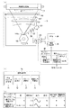
図2は、作像条件変更部としての露光部13の構成と、露光部13が感光体としての感光体ドラム11を走査露光する状態とを説明する図である。
露光部13は、半導体レーザからなる光源101、コリメータレンズ102、シリンダーレンズ103、例えば正六角面体で形成された回転多面鏡(ポリゴンミラー)104を有している。また、露光部13は、fθレンズ(集光レンズ)105、折り返しミラー106、反射ミラー107およびSOS(Start Of Scan)センサ108をさらに有している。
FIG. 2 is a diagram for explaining the configuration of the
The
露光部13において、光源101から出射された発散性のレーザ光Lは、コリメータレンズ102によって平行光に変換される。そして、副走査方向にのみ屈折力を持つシリンダーレンズ103により、ポリゴンミラー104の偏向反射面104a近傍にて主走査方向に長い線像として結像される。そして、レーザ光Lは、高速で定速回転するポリゴンミラー104の偏向反射面104aにより反射され、等角速度的に反時計回り(矢印C方向)に走査される。
In the
次に、レーザ光Lは、fθレンズ105を通過した後、折り返しミラー106により感光体ドラム11の表面に向けて方向を変えられ、感光体ドラム11の表面を矢印D方向に走査露光する。ここで、fθレンズ105は、レーザ光Lの光スポットの走査速度を等速化する機能を有している。また、前述した線像は、ポリゴンミラー104の偏向反射面104aの近傍に結像し、fθレンズ105は副走査方向に関して偏向反射面104aを物点として光スポットを感光体ドラム11の表面上に結像させる。したがって、この走査光学系は、偏向反射面104aの面倒れを補正する機能を有している。
Next, after the laser beam L passes through the fθ lens 105, the direction is changed toward the surface of the
また、レーザ光Lは、感光体ドラム11の表面上を走査露光するのに先立ち、反射ミラー107を介してSOSセンサ108に入射する。すなわち、SOSセンサ108には、レーザ光Lが感光体ドラム11の表面を走査する毎に、各走査ラインの最初のレーザ光Lが入射される。そして、SOSセンサ108は、感光体ドラム11の表面への走査ライン毎の照射タイミングを検知し、照射開始タイミングを示す信号(後述するSOS信号)を生成する。
The laser beam L is incident on the
光源101には、画像信号生成部(Image Processing System:IPS)60から出力された書込用画像データに応じたレーザ駆動信号を所定のタイミングで出力するレーザドライバ109が接続されている。レーザドライバ109は、IPS60からの書込用画像データに基づいて光源101の半導体レーザのON/OFFを制御する。それにより、光源101から書込用画像データに対応したレーザ光Lが出力される。
The
また、レーザドライバ109はエンジンコントローラ80に接続されており、エンジンコントローラ80内の駆動信号生成部A802Aが生成する駆動信号が入力される。そして、レーザドライバ109は、駆動信号に基づいて、光源101の半導体レーザに対してレーザ駆動信号の出力を開始するタイミングを設定する。
The
また、レーザドライバ109はSOSセンサ108に接続されており、SOSセンサ108において生成されたSOS信号が入力される。そして、レーザドライバ109は、SOSセンサ108からのSOS信号に基づいて、光源101の半導体レーザに対してレーザ駆動信号の出力を開始するタイミングを設定する。
The
ここで、レーザドライバ109は、エンジンコントローラ80が生成する駆動信号およびSOSセンサ108からのSOS信号に基づき、光源101の半導体レーザを制御するが、それぞれ用途が異なる。エンジンコントローラ80が生成する駆動信号は、いわゆる垂直同期信号であり、感光体ドラム11に代表されるモジュールの動作との同期を計るものである。SOSセンサ108からのSOS信号は、いわゆる水平同期信号であり、レーザの主走査方向における画像の位置制御に用いられる。
Here, the
さらに、レーザドライバ109には、濃度補正部70から濃度変動信号が入力されている。この濃度補正部70は、感光体ドラム11や現像装置14(図1参照)における現像ロール(後述)等、複数のユニットそれぞれに起因する副走査方向の濃度変動の信号を生成してレーザドライバ109に出力する。レーザドライバ109では、濃度補正部70から入力される濃度変動信号に基づいて、光源101の半導体レーザから出力されるレーザ光Lの光量を調整する。なお、レーザ光Lの光量調整は、後述するようにSOS信号が検知されてから実際に感光体ドラム11の表面を走査露光するまでの間に行われる。また、濃度補正部70は、エンジンコントローラ80に接続されており、エンジンコントローラ80が生成するモジュール駆動信号が入力される。濃度補正部70は、モジュール駆動信号に基づき濃度変動の算出を行うが、これについては後述する。
Further, a density variation signal is input from the
ここで、調整されるレーザ光Lの光量について説明する。
通常、露光処理の際に用いる光量は、例えば、画像形成部の最大濃度が目標値と一致するようにキャリブレーションを行うことにより、一定のパワーを保っている。説明を簡易にするため、画像形成部の光量と濃度が比例の関係にあると仮定すると、発生する濃度ムラと逆特性の係数を用いて、光量を制御することにより、濃度ムラを抑制することが可能である。つまり、目標とする濃度が1.0であり、変動により濃度が0.9〜1.1に振れる場合、濃度1.0の時の光量を1.0とすると、光量を濃度変動の逆数である1/0.9〜1/1.1にすることにより、濃度ムラを抑制することが可能である。
このように、本実施の形態では、濃度補正部70が設定した濃度変動信号に基づいて露光部13を制御することにより、副走査方向に対する濃度ムラを抑制する。
Here, the amount of laser light L to be adjusted will be described.
Normally, the amount of light used in the exposure process is kept constant by performing calibration so that the maximum density of the image forming unit matches the target value, for example. For the sake of simplicity, assuming that the light quantity and density of the image forming unit are proportional to each other, density unevenness is suppressed by controlling the light quantity using a coefficient having a characteristic opposite to the density unevenness that occurs. Is possible. In other words, if the target density is 1.0 and the density fluctuates from 0.9 to 1.1 due to fluctuation, if the light quantity at density 1.0 is 1.0, the light quantity is 1 / 0.9 to 1 / 1.1, which is the reciprocal of density fluctuation. Thus, density unevenness can be suppressed.
Thus, in the present embodiment, density unevenness in the sub-scanning direction is suppressed by controlling the
次に、図3に示すフローチャートを用いて、濃度補正部70における濃度変動データ設定処理の詳細を説明する。また、図2(b)を参照しながら濃度補正部70の構成を説明する。図2(b)に示すように、濃度補正部70は、補正パラメータ記憶部71、パターン生成部72、パターン選択部73、濃度ムラ予測部74、光量算出部75から構成される。なお、この光量補正データ設定処理は任意のタイミングで実行されるもので、通常、画像形成部の電源投入直後や長時間経過後などに行われる。
Next, details of the density variation data setting process in the
補正パラメータ記憶部71は、画像形成部の固有の周期(装置固有の周期)、すなわち周期濃度ムラの発生要因となるモジュールとその濃度ムラの発生する色Cl、周期P、波形f、振幅A、初期位相α、駆動信号カウントCnを記憶している。図2(c)に予め算出され記憶されたモジュール名とその濃度ムラの発生する色Cl、周期P、波形f、振幅A、初期位相α、駆動信号カウントCnのテーブルの例を示す。ここで、濃度ムラの発生する色Clは、各モジュール固有のものである。
The correction
例えば、画像形成ユニット10は、CMYKそれぞれの色に対して独立に作用するものであり、画像形成ユニット10Kに含まれるモジュールは、K色にのみ濃度ムラを発生させる。また、中間転写ベルトはCMYK全色に対して、作用する。モジュールの持つ周期Pは、画像形成部から出力される用紙上に現れる濃度ムラの周期であり、各モジュールの回転速度(単位時間あたりの回転数)と、感光体ドラムや中間転写ベルトの駆動速度(単位時間あたりの移動距離)から容易に算出可能である。
For example, the image forming unit 10 operates independently for each color of CMYK, and the module included in the
波形fに関しては、予め濃度パターンを取得しておくことにより、適切なパターンを記憶しておくことが可能である。また、各モジュールの振幅A、初期位相α、駆動信号カウントCnは以降の処理により適切な値を取得するため、初期値として振幅A=0.1、初期位相α=0ラジアン、カウントCn=0を設定している。本実施形態では、濃度ムラの発生要因となるモジュールを、図示しない感光体ドラム11Kの駆動ギアと中間転写ベルト20の駆動モータの2つとする。そして、それぞれの用紙上での濃度ムラ周期が2.5mm、32.0mmであり、その波形fは正弦波であるものとして説明する。 With respect to the waveform f, an appropriate pattern can be stored by acquiring a density pattern in advance. Further, the amplitude A, the initial phase α, and the drive signal count Cn of each module are acquired as appropriate values by subsequent processing, so that the amplitude A = 0.1, the initial phase α = 0 radians, and the count Cn = 0. Is set. In this embodiment, two modules that cause density unevenness are a drive gear for the photosensitive drum 11K and a drive motor for the intermediate transfer belt 20 (not shown). The description will be made assuming that the density unevenness period on each sheet is 2.5 mm and 32.0 mm, and the waveform f is a sine wave.
まず、パターン生成部72は、補正パラメータ記憶部71に記憶してあるモジュールの1つを選択する(S301)。モジュールが複数ある場合は、任意のモジュールを一つ選択し、後述のS308までの処理を行った後、S309にて全モジュールについて処理を終了したか判断し、終了していない場合には、残りのモジュールについて同様の処理を繰り返すものとする。ここでは、図2(c)に示すテーブルの一つ目のモジュールである感光体ドラム11Kの駆動ギアを選択し、次のステップに進む。パターン生成部72は、S301で選択されたモジュールの色Cl、周期Pおよび波形fを補正パラメータ記憶部71から読み込む(S302)。
First, the
次に、パターン生成部72は、S302おいて読み込んだモジュールの色Cl、周期P、波形fで、初期位相αの異なる補正を加えた複数のテストパターンを生成する(S303)。ここで、モジュールの周期、位相と駆動信号カウントの関係について説明する。モジュールが濃度ムラの原因となる場合、モジュールの周期で画像の濃度ムラが発生する。モジュールの駆動信号は、モジュールがどれだけの時間駆動(=回転)したかを示すものであり、この駆動信号をカウントすることにより、特定の時刻の位相を算出することができる。
Next, the
パターン生成部72は、補正パラメータ記憶部71の駆動信号カウントCnを所定のタイミングでリセットし、0に設定する。以降の処理で補正パラメータ記憶部71は、エンジンコントローラ80内の駆動信号生成部B802Bからのモジュール駆動信号を随時カウント(Cn=Cn+1)し、モジュールの周期P分のカウントに達する毎にCn=0にリセットする。
The
そして、パターン生成部72は、主走査方向の画像幅2cm、副走査方向の画像高さ3cm、面積率100%の均一な画像を出力するようにIPS60に信号を出力する。IPS60は、パターン生成部72からの信号にもとづきテストパターン画像を生成し、レーザドライバ109に送信する。
Then, the
平行して、パターン生成部72は下記の式1により算出した初期位相αiの異なる複数の濃度変動ODvarをレーザドライバ109に随時送信する。
ODvar=A・f(2π/P・Cn+αi)・・・(式1)
ここで、Aは振幅、fは波形を表す関数、Pは選択されたモジュールの周期、Cnは駆動信号のカウント値、αiはテストパターンの初期位相である。なお、周期Pは駆動信号Cnと同じ単位に変換されたものである。また、初期位相αiは、0から2πまで1/32π刻みで、64のテストパターンに別々に与えられる。ここで、fが正弦波であれば、式2で表すことができる。
ODvar=A・sin(2π/P・Cn+αi)・・・(式2)
なお、本実施形態では式により算出するが、モジュール周期P、駆動信号カウント値Cn、初期位相αと振幅値の関係を示すルックアップテーブル(LUT)などを用いることも可能である。
In parallel, the
ODvar = A · f (2π / P · Cn + αi) (Formula 1)
Here, A is the amplitude, f is a function representing the waveform, P is the period of the selected module, Cn is the count value of the drive signal, and αi is the initial phase of the test pattern. Note that the period P is converted into the same unit as the drive signal Cn. The initial phase αi is separately given to 64 test patterns in increments of 1 / 32π from 0 to 2π. Here, if f is a sine wave, it can be expressed by Equation 2.
ODvar = A · sin (2π / P · Cn + αi) (Formula 2)
In this embodiment, the calculation is performed using an equation, but it is also possible to use a module period P, a drive signal count value Cn, a look-up table (LUT) indicating the relationship between the initial phase α and the amplitude value.
レーザドライバ109は、IPS60から出力された画像データに応じた所定の光量E0と、パターン生成部から出力される初期位相αiの異なる濃度変動ODvarに基づいて、下記の式3から算出される光量Eでテストパターンの画像形成を行う。
E = E0×(ODtarget−ODvar)/ODtarget・・・(式3)
ここで、ODtargetは濃度変動が発生していない場合の濃度である。
The
E = E0 × (ODtarget−ODvar) / ODtarget (Equation 3)
Here, ODtarget is the density when no density fluctuation has occurred.
S301にて、モジュールとして感光体ドラム11Kの駆動ギアが選択された場合は、S302で取得した色K、周期2.5mm、正弦波を使用する。発生する濃度ムラの色、周期および波形は分かっているものの、その位相、振幅が未知である。そこで、振幅は所定値が設定され、初期位相を1/64周期ずつ変えた64パターンのテストパターンを作成し、各テストパターンに識別番号を付けて出力する。 If the driving gear for the photosensitive drum 11K is selected as the module in S301, the color K, the period of 2.5 mm, and the sine wave acquired in S302 are used. Although the color, period, and waveform of the density unevenness that occurs are known, the phase and amplitude are unknown. Therefore, a predetermined value is set for the amplitude, and 64 test patterns are generated by changing the initial phase by 1/64 period, and each test pattern is output with an identification number.
なお、モジュールの色が一色の場合、テストパターンはその色で出力される。また、複数ある場合は、任意の1色で出力するが、後述のパターン選択の容易さを考慮して選択する。例えば、CMYKに係わる中間転写体ベルトの場合は、テストパターンへの補正効果が判別しやすいKで出力される。また、各テストパターンの副走査方向のサイズは、そのモジュールの持つ周期の少なくとも1周期以上のサイズであることが望ましい。 When the module color is one color, the test pattern is output in that color. If there are a plurality of colors, they are output in one arbitrary color, but are selected in consideration of the ease of pattern selection described later. For example, in the case of an intermediate transfer belt related to CMYK, the correction effect on the test pattern is output with K that is easy to determine. Further, it is desirable that the size of each test pattern in the sub-scanning direction is at least one cycle of the cycle of the module.
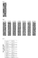
図4(a)は、光量補正を行わずに出力した画像のイメージである。図4(b)は、異なる複数の位相で補正を加えた画像の出力イメージである。図4(c)は、64パターンの補正画像が識別番号と共に用紙に出力された際のイメージ図である。なお、画像補正を加える前のテストパターンは、ある程度の面積を持った100%のベタ画像とするが、画像の濃度レンジやハーフトーンの有無など特に限定されるものではなく、補正効果の違いが確認できれば構わない。 FIG. 4A shows an image output without performing light amount correction. FIG. 4B is an output image of an image corrected with a plurality of different phases. FIG. 4C is an image diagram when 64 patterns of corrected images are output to a sheet together with an identification number. The test pattern before image correction is a 100% solid image having a certain area, but there is no particular limitation on the density range of the image or the presence or absence of a halftone, and there is a difference in correction effect. It does not matter if it can be confirmed.
次に、S303により生成された位相が異なる複数のテストパターンから、濃度ムラが最も小さいテストパターンとして選択されたテストパターンの識別番号を入力する(S304)。この際、テストパターンの選択は目視により行われ、図示しない入力装置を通してパターン選択部73に入力される。
つまり、発生する濃度ムラの位相が不明であるため、S303にて初期位相の異なる補正をかけたテストパターンを生成し、S304において、最も補正効果の高かったものを選択することで、実際の濃度ムラの位相を推定する。
Next, the identification number of the test pattern selected as the test pattern with the smallest density unevenness from the plurality of test patterns having different phases generated in S303 is input (S304). At this time, the test pattern is visually selected and input to the
That is, since the phase of the density unevenness to be generated is unknown, a test pattern with different initial phases is generated in S303, and the pattern having the highest correction effect is selected in S304. Estimate the phase of unevenness.
図4(b)は、テストパターン画像の書き出しタイミングを基準として、濃度ムラが位相2/32π(図4(b)左)ずれている、すなわち、画像書き出しタイミングに濃度ムラの位相が2/32πであると仮定し、補正を施したテストパターン画像の例である。同様に、他のテストパターン画像は、濃度ムラの位相を3/32π、4/32π、5/32π、6/32π、7/32π、8/32π、であると仮定し、補正を施したテストパターン画像の例を示す図である。 In FIG. 4B, the density unevenness is shifted by phase 2 / 32π (left of FIG. 4B) with reference to the test pattern image writing timing. That is, the density unevenness phase is 2 / 32π at the image writing timing. This is an example of a test pattern image that is corrected under the assumption that Similarly, in other test pattern images, it is assumed that the phase of density unevenness is 3 / 32π, 4 / 32π, 5 / 32π, 6 / 32π, 7 / 32π, and 8 / 32π, and the corrected test is performed. It is a figure which shows the example of a pattern image.
この例では、画像の書き出しタイミングを基準として、6/32π程度位相がずれた濃度ムラが発生していると推定可能である。位相情報の推定精度は、作成するパターンの位相を振るレンジで決まる。このため、テストパターン画像を出力できる枚数や用紙サイズ、許容される位相推定精度に応じて、位相を振るレンジを変えることが可能である。 In this example, it can be estimated that density unevenness having a phase shift of about 6 / 32π occurs with reference to the image writing timing. The estimation accuracy of the phase information is determined by the range in which the phase of the pattern to be created is shaken. For this reason, it is possible to change the range of phase shift according to the number of test pattern images that can be output, the paper size, and the allowable phase estimation accuracy.
ここで、S303においてテストパターンを生成する際に、振幅の設定を任意とした理由について説明する。
光量補正の際、振幅が異なっていると、最適な補正が行われず濃度ムラが残ってしまう。しかしながら、位相のずれた画像に補正処理を行うことで濃度ムラは悪化するため、相対的に位相の最も近い画像が最も平坦に見える。このため、現時点では適切に設定されていなくてもかまわない。振幅は、後述のS308にて、適切な値が設定される。なお、振幅値は任意であるが、0にした場合には、生成されるテストパターン間で濃度ムラの差が発生しないため意味をなさない。実際に発生する濃度ムラと近い値、かつ、視認できるレベルが望ましく、ダイナミックレンジの1/128〜1/16程度が妥当と思われる。さらに、濃度ムラの発生要因となるモジュールが複数ある場合は、未だ補正パラメータを算出していないモジュールに対しての補正が行われていないテストパターンから最も濃度ムラのないパターンを選択することになる。この場合においても、正しいパラメータの画像が相対的に最も濃度ムラが目立たなくなるため、問題ない。
Here, the reason why the amplitude is arbitrarily set when the test pattern is generated in S303 will be described.
When the light amount is corrected, if the amplitude is different, the optimum correction is not performed and density unevenness remains. However, the density unevenness is worsened by performing the correction process on the phase-shifted image, so that the image having the closest phase appears to be flattest. For this reason, it does not need to be set appropriately at this time. An appropriate value is set for the amplitude in S308 described later. Although the amplitude value is arbitrary, if it is set to 0, there is no difference in density unevenness between the generated test patterns, which makes no sense. A value close to the actually occurring density unevenness and a level that can be visually recognized are desirable, and a dynamic range of about 1/128 to 1/16 is considered appropriate. Further, when there are a plurality of modules that cause density unevenness, a pattern having the least density unevenness is selected from test patterns that have not been corrected for modules for which correction parameters have not yet been calculated. . Even in this case, there is no problem because the density unevenness becomes relatively inconspicuous in the image having the correct parameter.
次に、補正パラメータ記憶部71は、S304にて入力された識別番号に基づく初期位相を、調整対象のモジュールに対応させて補正パラメータ記憶部71に記憶する(S305)。
Next, the correction
次に、パターン生成部72は、S305で補正パラメータ記憶部71に記憶された初期位相αで振幅の異なる複数のテストパターンを印字してテスト画像作成を行う(S306)。ここで、テストパターンの生成はS303と同様に、IPS60にテストパターン画像を送信し、対象モジュールの駆動カウントCnを用いてレーザドライバ109に濃度変動ODvarを送信する。ここでODvarは以下の式により算出される。
ODvar=Ai・f(2π/P・Cn+α)・・・(式4)
ここでAiは、64のテストパターンに別々に与えられる振幅であり、テストパターン画像を出力できる枚数や用紙サイズ、許容される振幅推定精度に応じて、決定することが可能である。また、初期位相αは、S305で記憶されているモジュールの初期位相である。
Next, the
ODvar = Ai · f (2π / P · Cn + α) (Formula 4)
Here, Ai is an amplitude separately given to the 64 test patterns, and can be determined according to the number of sheets that can be output with the test pattern image, the paper size, and the allowable amplitude estimation accuracy. The initial phase α is the initial phase of the module stored in S305.
次に、パターン選択部73は、S304と同様に、もっとも適切に補正されているテストパターンの識別番号を入力する(S307)。次に、補正パラメータ記憶部71は、選択されたパターン番号から、発生している濃度ムラの振幅を記憶する(S308)。
以上の処理を実行することにより、補正パラメータ記憶部71は、感光体ドラムの駆動ギアに起因する初期位相α、振幅Aを記憶することが可能である。
Next, similarly to S304, the
By executing the above processing, the correction
つづいて、対象となるモジュール全てに対し位相および振幅のパラメータ設定が終了したかを判断し(S309)、終了していなければ、S301に戻り、全モジュールに対して、S302からS308までの処理を繰り返す。 Subsequently, it is determined whether the phase and amplitude parameter settings have been completed for all the target modules (S309). If not completed, the process returns to S301, and the processes from S302 to S308 are performed for all modules. repeat.
ここで、以上の処理がモジュール毎に行われる理由を説明する。各モジュールの周期が同じでない場合、画像出力するタイミングに応じて各モジュールの位相の変動量が異なる。このため、複数のモジュールに対して適切な初期位相、振幅を推定しようとすると、その組み合わせは膨大になり、(例えば、二つのモジュールの位相を一度に推定する場合、必要なテストパターン数は64×64=4096になる)、現実的でない。なお、複数のモジュールの周期が同じ、もしくは整数倍の場合は、同時に処理を行うことが可能である。 Here, the reason why the above processing is performed for each module will be described. When the period of each module is not the same, the amount of phase variation of each module differs depending on the timing of image output. For this reason, when trying to estimate appropriate initial phases and amplitudes for a plurality of modules, the number of combinations becomes enormous. (For example, when estimating the phases of two modules at a time, the number of necessary test patterns is 64. X64 = 4096), which is not realistic. In addition, when the period of a some module is the same or it is an integral multiple, it is possible to process simultaneously.
次に、濃度補正部70が各モジュールの色Cl、周期P、波形f、振幅A、初期位相α、駆動信号カウントCnを用いて行う光量補正について図5のフローチャートを用いて説明する。
濃度ムラ予測部74は、補正パラメータ記憶部71から全モジュールの色Cl、周期P、波形f、振幅A、初期位相α、駆動信号カウントCnを取得する(S501)。この際、補正パラメータ記憶部71は、S303以降、継続して駆動信号をカウントしているため、各モジュールの位相が把握可能である。
Next, light amount correction performed by the
The density
さらに、濃度ムラ予測部74は、以下の式に基づき全モジュールの重畳された濃度変動ODvar_sumを算出する(S502)。
ODvar_sum = Σ Ai・fi(2π/Pi・Cni+αi)・・・(式5)
ここで、iは各モジュールに付与されている番号である。
Furthermore, the density
ODvar_sum = ΣAi · fi (2π / Pi · Cni + αi) (Formula 5)
Here, i is a number assigned to each module.
次に、レーザドライバは、IPS60と濃度ムラ予測部74から出力される情報に基づき画像形成を行う(S503)。濃度ムラ予測部74は、算出した濃度変動ODvar_sumをレーザドライバ109に随時送信する。レーザドライバ109は、IPS60から出力された画像データに応じた所定の光量E0と、濃度変動ODvar_sumに基づいて、下記の式から算出される光量Eで画像形成を行う。
E = E0×(ODtarget−ODvar_sum)/ODtarget・・・(式6)
なお、上記の処理は、モジュールの色Clに対して行われるものであり、Clが単色の場合は、例えばKであれば、K色にのみ行う。Clが複数色ある場合は、すべての色に対して同様に処理を行う。以上の処理により、画像出力に際して適切な濃度ムラ補正を行うことが可能となる。
Next, the laser driver forms an image based on information output from the
E = E0 × (ODtarget−ODvar_sum) / ODtarget (Expression 6)
The above processing is performed for the module color Cl. When Cl is a single color, for example, if it is K, it is performed only for the K color. When there are a plurality of colors of Cl, the same processing is performed for all colors. With the above processing, it is possible to perform appropriate density unevenness correction upon image output.
以上説明した処理制御を行うことで、高精度なセンサを必要とすることなく、モジュールの周期性に起因する濃度ムラの位相、振幅を精度良く算出することが可能となり、濃度ムラを安価な構成で抑制することが可能となる。
なお、本実施形態では、濃度ムラ要因となるモジュールを感光体ドラムの駆動ギアと中間転写ベルトの駆動モータとして説明した。しかし、その他の帯電装置、露光装置、現像装置、転写装置、定着装置などを構成するモジュールを用いて実現しても同様の効果を得ることができる。また、画像形成部の固有の周期は、モジュールの周期、位相、振幅、波形のうち、少なくとも1つで規定されるようにする。
By performing the processing control described above, it is possible to accurately calculate the phase and amplitude of density unevenness due to the periodicity of the module without the need for a highly accurate sensor. Can be suppressed.
In this embodiment, the module that causes density unevenness has been described as the drive gear for the photosensitive drum and the drive motor for the intermediate transfer belt. However, the same effect can be obtained even if it is realized by using modules constituting other charging devices, exposure devices, developing devices, transfer devices, fixing devices and the like. The specific period of the image forming unit is defined by at least one of the module period, phase, amplitude, and waveform.
また、本実施形態では、全モジュールに対してS302からS308までの処理を繰り返すものとして説明した。これに代わって、2番目以降のモジュールに対しては、既にパラメータ設定処理が終わっているモジュールの光量補正を行ったテストパターンを生成し、パラメータ推定を行う方法が考えられる。 In the present embodiment, the processing from S302 to S308 is repeated for all modules. In place of this, for the second and subsequent modules, a method of generating a test pattern in which the light intensity correction of the module for which parameter setting processing has already been completed is generated and parameter estimation is considered.
また、本実施形態では、S301において、モジュールが複数ある場合に、任意のモジュールを一つ選択するものとした。これに代わって、各モジュールのパラメータ算出における順序を目視確認のし易さを考慮して決定する方法も考えられる。例えば、モジュールの周期がより長いモジュールから処理を行う方法。濃度ムラの周波数に対する人間の視覚感度特性(VTF)が高いモジュールから処理を行う方法。予め画像形成部の設計値から振幅が強い変動が発生する可能性の高いモジュールから処理を行う方法等が考えられる。 In the present embodiment, when there are a plurality of modules in S301, one arbitrary module is selected. Instead of this, a method may be considered in which the order of parameter calculation for each module is determined in consideration of ease of visual confirmation. For example, a method of performing processing from a module having a longer module cycle. A method of processing from modules with high human visual sensitivity characteristics (VTF) for frequency of density unevenness. A method of performing processing from a module that is highly likely to cause a strong fluctuation in amplitude from the design value of the image forming unit in advance can be considered.
(第2の実施形態)
第1の実施形態では、サンプル出力して選択されたパターンから補正量を設定する方法について説明した。本実施形態においては、内蔵されたセンサを用いて補正量を設定する例について説明する。なお、濃度センサの使用と濃度補正部70のフロー以外の構成は、第1の実施形態と同じであるため、説明を省略する。
(Second Embodiment)
In the first embodiment, the method of setting the correction amount from the pattern selected by outputting the sample has been described. In the present embodiment, an example in which a correction amount is set using a built-in sensor will be described. Since the configuration other than the use of the density sensor and the flow of the
本実施形態では、中間転写ベルト20に濃度検知部としての濃度センサ(濃度検出装置)28が対向配置されている。濃度センサ28は、黒の画像形成ユニット10Kに隣接して配置されており、中間転写ベルト20上に一次転写された各色のトナー像の濃度を検知する。
次に、図3に示すフローチャートを用いて、濃度補正部70における光量補正データ設定処理の詳細を説明する。
In the present embodiment, a density sensor (density detection device) 28 serving as a density detection unit is disposed opposite to the
Next, details of the light amount correction data setting process in the
まず、パターン生成部72は、補正パラメータ記憶部71に記憶してあるモジュールの1つを選択する(S301)。
次に、パターン生成部72は、予め記憶している周期濃度ムラの発生要因となるモジュールのパラメータを補正パラメータ記憶部71から読み込む(S302)。
次に、パターン生成部72は、S302で補正パラメータ記憶部71から読み込んだモジュールの持つ周期で、初期位相の異なる補正を加えた複数のテストパターンを生成する(S303)。
First, the
Next, the
Next, the
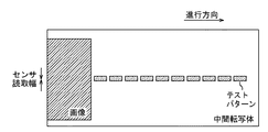
本実施形態においては、振幅は任意に設定し、初期位相を1/64周期ずつ変えた64パターンの画像を作成し、図6の模式図に示すように中間転写ベルト20にテストパターンを印字する。テストパターンは、濃度センサ28で読み取り可能な位置に並べて配置されており、中間転写ベルト20の駆動に合わせて、パターンを走査する形で濃度を読み取り可能である。なお、印字されたパターンは、用紙に転写される必要はなく、ベルトクリーナ27によってクリーニングされる。
In this embodiment, the amplitude is arbitrarily set, 64 patterns of images having initial phases changed by 1/64 period are created, and a test pattern is printed on the
次に、パターン選択部73は、濃度センサ28の出力値から最も濃度ムラがないパターンを選択する(S304)。ここで、濃度センサ28はテストパターンの開始位置と同期して、単位時間ごとに検出信号を出力する。出力信号は、濃度センサ28を構成する受光部が単位時間に受けた光量を電気信号として出力するものであり、画像の濃度として扱うことが可能である。単位時間は測定したい周期に対して十分に小さければよく、画像形成部の出力解像度レベルの濃度波形を検出できる必要はない。最も濃度ムラがないパターンは、濃度センサ28の出力信号のばらつき、最大値と最小値の差などの統計量をもとに容易に選択することが可能である。このため、濃度の絶対値の精度や、濃度波形を保存しておくメモリ等を省略できるため、従来技術で用いられている濃度センサより、簡易もしくは安価な濃度センサを利用することが可能である。
Next, the
次に、補正パラメータ記憶部71は、選択されたパターン番号から、基準波形との初期位相として記憶する(S305)。
次に、パターン生成部72は、S305で補正パラメータ記憶部71に記憶された位相で、振幅の異なる複数のテストパターンを中間転写ベルト20に印字する(S306)。次に、パターン選択部73は、濃度センサ28の出力値から最も濃度ムラがないパターンを選択する(S307)。
Next, the correction
Next, the
次に、補正パラメータ記憶部71は、選択されたパターン番号から、発生している濃度ムラの振幅を記憶する(S308)。
以上の処理で、補正パラメータ記憶部71は、各モジュールの濃度ムラの初期位相、振幅を記憶することが可能である。
Next, the correction
Through the above processing, the correction
以上により、本実施形態においては、より安価なセンサで、モジュールの周期性に起因する濃度ムラを抑制することが可能となる。なお、本実施形態では、中間転写ベルト上で位相を推定するものとして説明したが、感光体ドラム上や用紙定着後などに濃度測定を行う方法で実現しても同様の効果を得ることができる。 As described above, in this embodiment, it is possible to suppress density unevenness due to the periodicity of the module with a cheaper sensor. In the present embodiment, the phase is estimated on the intermediate transfer belt. However, the same effect can be obtained even if the density measurement is performed on the photosensitive drum or after paper fixing. .
また、本実施形態では、位相および振幅の異なるテストパターンを連続して作成し、濃度センサによる読み取りを行っている。この過程で、センサの出力値のばらつきは、テストパターン毎になめらかに変化することが想定される。そこで、出力値のばらつきが最小となるパターンが検知された場合には、以降のパターン出力を省略することが可能である。 In the present embodiment, test patterns having different phases and amplitudes are continuously created and read by the density sensor. In this process, it is assumed that the variation in the output value of the sensor changes smoothly for each test pattern. Therefore, when a pattern having a minimum variation in output value is detected, subsequent pattern output can be omitted.
また、本実施形態では、位相および振幅のテストパターンの作成を連続して行ったが、通常の画像形成の間に、少量のパターン作成および測定を行い、随時キャリブレーションをかけるなどの利用も可能である。また、パターン選択部73は、ユーザの入力に応じて画像パターンを選択するようにしてもよい。
In this embodiment, phase and amplitude test patterns are continuously created. However, during normal image formation, a small amount of patterns can be created and measured, and calibration can be used as needed. It is. Further, the
なお、本実施形態では、濃度ムラの発生要因となるモジュールを感光体ドラムの駆動ギアと中間転写ベルトの駆動モータとした。その他にも帯電装置の印加電圧、露光装置のレーザ数、回転多面鏡(ポリゴンミラー)、感光体ドラムの偏芯/駆動モータ、現像ローラの偏芯/駆動ギア/駆動モータなどにも適用可能である。また、転写ローラの偏芯/駆動ギア/駆動モータ、中間転写ベルトの駆動ギア、定着ローラの偏芯/駆動ギア/駆動モータ、レジストレーションロールの偏芯/駆動ギア/駆動モータなどの周期性を持つモジュールに対しても適用可能であることは、いうまでもない。 In this embodiment, the modules that cause density unevenness are the driving gear for the photosensitive drum and the driving motor for the intermediate transfer belt. In addition, it can also be applied to the applied voltage of the charging device, the number of lasers of the exposure device, rotary polygon mirror, eccentricity / drive motor of the photosensitive drum, eccentricity / drive gear / drive motor of the developing roller, etc. is there. Also, transfer roller eccentricity / drive gear / drive motor, intermediate transfer belt drive gear, fixing roller eccentricity / drive gear / drive motor, registration roll eccentricity / drive gear / drive motor, etc. Needless to say, the present invention can also be applied to the modules that it has.
(第3の実施形態)
第1の実施形態では、位相および振幅の設定方法の一連の処理について説明した。本実施形態では、画像形成部の状態に応じて省略できる工程を考慮した、条件分岐を含む例について説明する。なお、特に記述のない構成は、第1の実施形態と同じであるため、説明を省略する。
(Third embodiment)
In the first embodiment, a series of processing of the phase and amplitude setting method has been described. In the present embodiment, an example including conditional branching will be described in consideration of processes that can be omitted depending on the state of the image forming unit. The configuration not particularly described is the same as that of the first embodiment, and thus the description thereof is omitted.
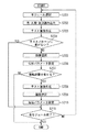
以下、図7に示すフローチャートを用いて、濃度補正部70における濃度変動データ設定処理の詳細を説明する。
S701、S702、S703の各ステップはそれぞれ、第1の実施形態のS301、S302、S303と同じであるため、説明を省略する。本実施形態においては、S703およびS708においてテストパターンを生成する。このため、S703において行われる処理を第1のパターン生成処理、S708において行われる処理を第2のパターン生成処理とする。
次に、S703により生成された位相が異なる複数のテストパターンの印字結果に応じて、以降の処理の分岐を行う(S704)。図8は、S704におけるテストパターンの入力に係るユーザインターフェースの一例である。
The details of the density variation data setting process in the
Each step of S701, S702, and S703 is the same as S301, S302, and S303 of the first embodiment, and thus description thereof is omitted. In the present embodiment, a test pattern is generated in S703 and S708. For this reason, the process performed in S703 is referred to as a first pattern generation process, and the process performed in S708 is referred to as a second pattern generation process.
Next, the subsequent processing is branched in accordance with the print results of a plurality of test patterns having different phases generated in S703 (S704). FIG. 8 is an example of a user interface related to the input of the test pattern in S704.
まず、S704において、複数のテストパターン間に差が認められるか否かを判定する。差が認められる場合には、第1の実施形態のS304と同様にテストパターンの認識番号が入力され、第1の選択が行われる(S705)。この際には、第1の実施形態と同様に識別番号の入力は、例えば、図示しない入力装置上に表示される図8(a)に示すユーザインターフェースから行われる。識別番号入力は、識別番号表示部8001に図示しないキーボード等から数値を入力する方法や、プルダウンボタン8002を用いて識別番号を選択する等の方法が考えられる。また、入力の決定は、エンターボタン8003から行う等の方法が考えられうる。
First, in S704, it is determined whether or not a difference is recognized between a plurality of test patterns. When the difference is recognized, the test pattern recognition number is input in the same manner as in S304 of the first embodiment, and the first selection is performed (S705). In this case, as in the first embodiment, the identification number is input from, for example, a user interface shown in FIG. 8A displayed on an input device (not shown). For the identification number input, a method of inputting a numerical value from a keyboard or the like not shown in the identification
一方、S704の判定において、複数のテストパターン間に差が認められない場合は、ボタン8004をクリックする等して、S711に移行する。この際、補正パラメータ記憶部71は、初期位相に変更を加えず、振幅には0を設定し、記憶する。以上の処理をもって、S701にて設定されているモジュールの濃度変動データ設定処理を終了する。S711は、第1の実施形態のS309と同じであるため説明を省略する。
On the other hand, if there is no difference between the plurality of test patterns in the determination of S704, the process proceeds to S711 by clicking a
ここで、S704分岐処理の意図について説明する。
S703にて生成された複数のテストパターン間に差が認められない場合は、テストパターン生成時に設定した振幅値相当の濃度ムラが全てのテストパターンに発生している状態である。すなわち、実際にはS701にて設定されているモジュールの周期の濃度ムラは発生していない、もしくは、視認できないレベルであると考えられる。そこで、補正パラメータ記憶部71には、S701にて設定されているモジュールの振幅値0を設定し、実質的に光量補正を行わない。なお、初期位相には、変更を加えないものとしたが、振幅値0では実質的に光量補正が行われないため、任意の値を設定しても構わない。S704の分岐処理を行うことで、以降のS705〜S710を省略し、補正パラメータの取得精度を落とすことなく、処理にかかる時間を短縮することが可能である。
Here, the intention of the S704 branching process will be described.
If no difference is recognized between the plurality of test patterns generated in S703, the density unevenness corresponding to the amplitude value set at the time of test pattern generation is occurring in all the test patterns. That is, it is considered that the density unevenness of the module period set in S701 does not actually occur or is invisible. Therefore, the correction
次に、複数のテストパターン間に差が認められた場合は、第1の実施形態のS305と同様に、識別番号に基づく初期位相を補正パラメータ記憶部71に記憶する(S706)。
次に、S705において選択された識別番号のテストパターンの印字結果に応じて、以降の処理の分岐を行う(S707)。
Next, when a difference is recognized between a plurality of test patterns, the initial phase based on the identification number is stored in the correction
Next, the subsequent processing is branched according to the print result of the test pattern of the identification number selected in S705 (S707).
S705において選択された識別番号のテストパターンの濃度ムラが視認できない場合。もしくは、許容範囲であるので振幅調整が不要の場合、S703でテストパターン作成に用いた振幅値で光量補正を行うことで、画像出力時に適切な濃度ムラ補正を行うことが可能である。つまりは、S701にて設定されているモジュールの振幅設定(第1の実施形態におけるS306〜S308と同じS708〜S710)。およびS701において未だ選択されていないモジュールのパラメータ設定を行っても、これ以上の補正効果を持つパラメータを設定することは困難である。 When the density unevenness of the test pattern having the identification number selected in S705 cannot be visually recognized. Alternatively, if the amplitude adjustment is unnecessary because it is within the allowable range, it is possible to perform appropriate density unevenness correction at the time of image output by performing light amount correction with the amplitude value used for test pattern creation in S703. That is, the amplitude setting of the module set in S701 (S708 to S710, which is the same as S306 to S308 in the first embodiment). Even if parameter setting is performed for a module that has not yet been selected in step S701, it is difficult to set a parameter having a further correction effect.
そこで、現在、濃度変動データ設定を行っているモジュールの振幅値をS703でテストパターン作成に用いた振幅値として、補正パラメータ記憶部71に記憶する。また、S701において未だ選択されていないモジュールの振幅値は、0に設定し、補正パラメータ記憶部71に記憶し、濃度変動データ設定処理を終了する。図8(b)はS706に係るユーザインターフェースの一例である。上記の処理への分岐は、図8(b)のボタン8005を選択する等して行われる。
Accordingly, the amplitude value of the module for which density variation data is currently set is stored in the correction
一方、S707の判定において、S705において選択された識別番号のテストパターンの濃度ムラが許容範囲外であり、振幅調整を要する場合は、図8(b)のボタン8006を選択する等して、以降のS708〜S710の処理に移行する。これにより、適切な振幅値を設定することが可能である。
On the other hand, if it is determined in S707 that the density unevenness of the test pattern with the identification number selected in S705 is outside the allowable range and amplitude adjustment is required, the
前述のように第3の実施形態では、S707の判定に応じて分岐処理を行うことで、以降のS708における第2のパターン生成、S709における第2の選択処理、S710における振幅パラメータ作成を省略する。さらに、S701において未だ選択されていないモジュールの濃度変動データ設定処理を省略し、補正パラメータの取得精度を落とすことなく、処理にかかる時間を短縮することが可能である。S709における第2の選択処理においては、S708で作成された複数の画像パターンの中から一つのテストパターンを選択するか否かを判定する。 As described above, in the third embodiment, the branch process is performed according to the determination in S707, thereby omitting the subsequent second pattern generation in S708, the second selection process in S709, and the amplitude parameter generation in S710. . Further, it is possible to omit the density variation data setting process for modules not yet selected in S701, and to shorten the processing time without degrading the acquisition accuracy of the correction parameters. In the second selection process in S709, it is determined whether one test pattern is selected from the plurality of image patterns created in S708.
(第4の実施形態)
第3の実施形態では、位相および振幅が未知である状態における処理について説明した。本実施形態では、前回調整時のパラメータを利用し、より高精度な調整が可能な例について説明する。なお、特に記述のない構成は、第3の実施形態と同じであるため、説明を省略する。
(Fourth embodiment)
In the third embodiment, processing in a state where the phase and amplitude are unknown has been described. In the present embodiment, an example in which more accurate adjustment is possible using the parameters at the time of previous adjustment will be described. Note that the configuration not particularly described is the same as that of the third embodiment, and thus the description thereof is omitted.
以下、図9に示すフローチャートを用いて、濃度補正部70における濃度変動データ設定処理の詳細を説明する。
S901、S902の各ステップはそれぞれ、第3の実施形態のS701、S702と同じであるため、説明を省略する。
次に、パターン生成部72は、後述のS915により記録されている前回の補正パラメータを補正パラメータ記憶部71から読み込む(S903)。続いて、パターン生成部72は、前回設定した初期位相と前回と今回の濃度変動データ設定処理の時間経過から、この後に続くテスト画像作成S905で作成するテストパターンの初期位相の範囲を決定する(S904)。
Hereinafter, the details of the density variation data setting process in the
Since each step of S901 and S902 is the same as S701 and S702 of the third embodiment, the description thereof is omitted.
Next, the
ここで、S904の詳細について、一例を示す。
まず、パターン生成部72は、補正パラメータ記憶部71から、前回の濃度変動データ設定処理からの総駆動カウントCn_total [01]を読み込む。パターン生成部72は、総駆動カウントCn_totalから、前回の処理で設定された初期位相からどの程度の範囲で位相誤差が発生しているかを算出する。
αmax_err=αerr/Cn・Cn_total・・・(式7)
ここで、αerr/Cnは各モジュールの単位カウントあたりの最大位相誤差、αmax_errは前回の処理で設定された初期位相からの最大位相誤差である。
Here, an example is shown about the detail of S904.
First, the
αmax_err = αerr / Cn · Cn_total (Expression 7)
Here, αerr / Cn is the maximum phase error per unit count of each module, and αmax_err is the maximum phase error from the initial phase set in the previous process.
なお、前回の処理で設定された初期位相からの最大位相誤差の算出方法は、画像形成部の設計に大きく依存するが、駆動信号カウントと単位カウントあたりの発生誤差を見積もる方法が考えられる。また、画像形成部の駆動時間あたりの誤差量、メイン電源のON/OFF回数などを基に算出する方法が考えられる。
そして、前回の濃度変動データ設定処理にて設定された初期位相αを読み込み、作成するテストパターンの初期位相の範囲αrangeを決定する。
αrange=α±αmax_err・・・(式8)
Note that the method of calculating the maximum phase error from the initial phase set in the previous process largely depends on the design of the image forming unit, but a method of estimating the drive signal count and the generated error per unit count can be considered. In addition, a calculation method based on an error amount per driving time of the image forming unit, the number of ON / OFF times of the main power source, and the like can be considered.
Then, the initial phase α set in the previous density variation data setting process is read, and the initial phase range αrange of the test pattern to be created is determined.
αrange = α ± αmax_err (Equation 8)
次に、パターン生成部72は、S904で算出された初期位相の範囲αrangeに基づいてテストパターンを生成する(S905)。ここで生成されるパターンは第1の実施形態の式1に基づいて行われるが、その初期位相αiは範囲αrange内である。生成するテストパターン数が固定であるとすると、範囲αrangeが第1の実施形態の0から2πより狭い場合、より細かい振り幅で複数の初期位相αiのテストパターンが生成されるため、初期位相の推定精度が向上する。例えば、範囲αrangeが0から1/3πであった場合は、2/(1/3)=6倍の精度で初期位相を推定することができる。続くS906〜S909は、第3の実施形態のS704〜S707と同じであるため、説明を省略する。
Next, the
次に、パターン生成部72は、S903で読み込んだ前回設定の振幅値に基づき、生成するテストパターンの振幅の範囲を決定する(S910)。設定される振幅の範囲は、位相と同様に画像形成部の設計に大きく依存する。ここでは、S904と同様の考えに基づき、以下の式9・10により算出する。
Amax_err=Aerr/Cn・Cn_total・・・(式9)
Arange=A±Amax_err・・・(式10)
この処理により、位相の推定精度と同様の理由で、振幅の推定精度を向上させることが可能である。以降のS911〜S914は、第3の実施形態のS708〜S711と同じであるため、説明を省略する。
Next, the
Amax_err = Aerr / Cn · Cn_total (Equation 9)
Arange = A ± Amax_err (Equation 10)
By this process, it is possible to improve the amplitude estimation accuracy for the same reason as the phase estimation accuracy. Subsequent S911 to S914 are the same as S708 to S711 of the third embodiment, and thus the description thereof is omitted.
次に、補正パラメータ記憶部71は、今回の濃度変動データ設定処理によって算出された位相および振幅パラメータを記憶する(S915)。記録されたパラメータは、以降の画像形成の光量補正パラメータとして利用される。また、次回の濃度変動データ設定処理に利用される。
Next, the correction
なお、本実施形態では、一度に生成するテストパターンの数が一定であるものとし、位相および振幅パラメータの推定精度が向上すると説明した。しかし、テストパターン数と補正パラメータの推定精度はトレードオフの関係にあるため、各パラメータの振り幅に閾値を設定し、テストパターン数を削減するなどの利用方法も考えられる。さらに、テストパターン数の削減に伴い、例えば複数のモジュールの位相パラメータ設定を一度に行うなどの利用方法も考えられる。 In the present embodiment, the number of test patterns generated at a time is assumed to be constant, and the estimation accuracy of the phase and amplitude parameters is improved. However, since the number of test patterns and the estimation accuracy of the correction parameters are in a trade-off relationship, a usage method such as setting a threshold value for the width of each parameter and reducing the number of test patterns can be considered. Furthermore, with the reduction in the number of test patterns, for example, a use method such as setting phase parameters of a plurality of modules at a time can be considered.
以上説明したように、第4の実施形態では、前回の補正パラメータを用いて今回設定するパラメータの探索範囲を限定することで、補正パラメータの推定精度の向上、もしくは、テストパターン数の削減を行うことが可能である。 As described above, in the fourth embodiment, the correction parameter estimation accuracy is improved or the number of test patterns is reduced by limiting the search range of the parameter set this time using the previous correction parameter. It is possible.
なお、その他の実施形態として、第2の実施形態に示す濃度センサを用いて、センサの精度内で各モジュールの位相や振幅の探索範囲を特定し、目視用テストパターンのパラメータ範囲や水準を絞り込むなどの形態も考えられる。また、もっとも濃度ムラの少ないテストパターンに加え、2番目に濃度ムラの少ないテストパターンも選択し、二つのテストパターンから補完してより高精度なパラメータ推定を行うなどの方法も考えられる。 As another embodiment, the concentration sensor shown in the second embodiment is used to specify the search range of the phase and amplitude of each module within the accuracy of the sensor, and the parameter range and level of the visual test pattern are narrowed down. Such forms are also conceivable. Further, in addition to the test pattern with the least density unevenness, a test pattern with the second lowest density unevenness is selected, and more accurate parameter estimation is performed by complementing the two test patterns.
(その他の実施形態)
また、本発明は、以下の処理を実行することによっても実現される。即ち、前述した実施形態の機能を実現するソフトウェア(コンピュータプログラム)を、ネットワーク又は各種のコンピュータ読み取り可能な記憶媒体を介してシステム或いは装置に供給する。そして、そのシステム或いは装置のコンピュータ(またはCPUやMPU等)がプログラムを読み出して実行する処理である。
(Other embodiments)
The present invention can also be realized by executing the following processing. That is, software (computer program) that implements the functions of the above-described embodiments is supplied to a system or apparatus via a network or various computer-readable storage media. Then, the computer (or CPU, MPU, etc.) of the system or apparatus reads out and executes the program.
Claims (12)
前記生成された複数の画像パターンの中から一つのテストパターンを選択する選択手段と、
前記選択手段により選択されたテストパターンに応じて画像の補正を行う画像補正手段と、
を有することを特徴とする画像処理装置。 Pattern generating means for causing the image forming unit to generate a plurality of different image patterns having a unique period of the image forming unit;
Selecting means for selecting one test pattern from the plurality of generated image patterns;
Image correcting means for correcting an image according to the test pattern selected by the selecting means;
An image processing apparatus comprising:
前記選択手段は、前記複数の画像パターンを前記濃度検出装置で測定し、出力された画像パターンの一つを選択することを特徴とする請求項1〜5の何れか1項に記載の画像処理装置。 In synchronization with the start position of the test pattern, a concentration detection device that outputs a detection signal every unit time,
The image processing according to claim 1, wherein the selection unit measures the plurality of image patterns with the density detection device and selects one of the output image patterns. apparatus.
前記第1のパターン生成手段により生成された画像パターンの中から一つのテストパターンを選択する第1の選択手段と、
前記第1の選択手段により選択されたテストパターンに対応する位相であり、振幅の異なる複数の画像パターンを前記画像形成部に生成させる第2のパターン生成手段と、
前記第2のパターン生成手段により生成された画像パターンの中から一つのテストパターンを選択する第2の選択手段と、
前記第1の選択手段により選択されたテストパターンの位相と前記第2の選択手段により選択されたテストパターンに対応する振幅とに応じて画像の補正を行う画像補正手段と、
を有することを特徴とする画像処理装置。 A first pattern generation unit that generates a plurality of image patterns having a unique period of the image forming unit and having different phases;
First selection means for selecting one test pattern from among the image patterns generated by the first pattern generation means;
A second pattern generation unit that causes the image forming unit to generate a plurality of image patterns having a phase corresponding to the test pattern selected by the first selection unit and having different amplitudes;
Second selection means for selecting one test pattern from the image patterns generated by the second pattern generation means;
Image correction means for correcting an image according to the phase of the test pattern selected by the first selection means and the amplitude corresponding to the test pattern selected by the second selection means;
An image processing apparatus comprising:
前記第1のパターン生成手段は、前記記録手段により記録されている情報に基づいて、位相、振幅の少なくとも1つが異なる複数の画像パターンを前記画像形成部に生成させることを特徴とする請求項7に記載の画像処理装置。 Recording means for recording information on the test pattern selected by the first selection means;
8. The first pattern generation unit causes the image forming unit to generate a plurality of image patterns having at least one of a phase and an amplitude based on information recorded by the recording unit. An image processing apparatus according to 1.
前記生成された複数の画像パターンの中から一つのテストパターンを選択する選択工程と、
前記選択工程において選択されたテストパターンに応じて画像の補正を行う画像補正工程と、
を有することを特徴とする画像処理装置の制御方法。 A pattern generation step for causing the image forming unit to generate a plurality of different image patterns having a unique period of the image forming unit;
A selection step of selecting one test pattern from the plurality of generated image patterns;
An image correction step of correcting an image according to the test pattern selected in the selection step;
A control method for an image processing apparatus, comprising:
前記第1のパターン生成工程において生成された画像パターンの中から一つのテストパターンを選択する第1の選択工程と、
前記第1の選択工程において選択されたテストパターンに対応する位相であり、振幅の異なる複数の画像パターンを前記画像形成部に生成させる第2のパターン生成工程と、
前記第2のパターン生成工程において生成された画像パターンの中から一つのテストパターンを選択する第2の選択工程と、
前記第1の選択工程において選択されたテストパターンの振幅と前記第2の選択工程において選択されたテストパターンに対応する振幅とに応じて画像の補正を行う画像補正工程と、
を有することを特徴とする画像処理装置の制御方法。 A first pattern generating step for causing the image forming unit to generate a plurality of image patterns having a unique period of the image forming unit and having different phases;
A first selection step of selecting one test pattern from the image patterns generated in the first pattern generation step;
A second pattern generation step for causing the image forming unit to generate a plurality of image patterns having different phases and phases corresponding to the test pattern selected in the first selection step;
A second selection step of selecting one test pattern from the image patterns generated in the second pattern generation step;
An image correction step for correcting an image according to the amplitude of the test pattern selected in the first selection step and the amplitude corresponding to the test pattern selected in the second selection step;
A control method for an image processing apparatus, comprising:
Priority Applications (2)
| Application Number | Priority Date | Filing Date | Title |
|---|---|---|---|
| JP2011095364A JP2012014149A (en) | 2010-05-31 | 2011-04-21 | Image processor and control method of the same |
| US13/115,873 US8717631B2 (en) | 2010-05-31 | 2011-05-25 | Image processing apparatus and method for controlling the image processing apparatus |
Applications Claiming Priority (3)
| Application Number | Priority Date | Filing Date | Title |
|---|---|---|---|
| JP2010124764 | 2010-05-31 | ||
| JP2010124764 | 2010-05-31 | ||
| JP2011095364A JP2012014149A (en) | 2010-05-31 | 2011-04-21 | Image processor and control method of the same |
Publications (2)
| Publication Number | Publication Date |
|---|---|
| JP2012014149A true JP2012014149A (en) | 2012-01-19 |
| JP2012014149A5 JP2012014149A5 (en) | 2014-05-22 |
Family
ID=45021901
Family Applications (1)
| Application Number | Title | Priority Date | Filing Date |
|---|---|---|---|
| JP2011095364A Pending JP2012014149A (en) | 2010-05-31 | 2011-04-21 | Image processor and control method of the same |
Country Status (2)
| Country | Link |
|---|---|
| US (1) | US8717631B2 (en) |
| JP (1) | JP2012014149A (en) |
Cited By (7)
| Publication number | Priority date | Publication date | Assignee | Title |
|---|---|---|---|---|
| JP2013228609A (en) * | 2012-04-26 | 2013-11-07 | Canon Inc | Image forming device |
| JP2014116711A (en) * | 2012-12-07 | 2014-06-26 | Konica Minolta Inc | Scan nonuniformity analysis device, image processing device and image forming apparatus |
| JP2015055747A (en) * | 2013-09-11 | 2015-03-23 | キヤノン株式会社 | Image forming apparatus, control apparatus, and control method thereof |
| JP2015158585A (en) * | 2014-02-24 | 2015-09-03 | 富士ゼロックス株式会社 | image forming apparatus and program |
| US9658564B1 (en) | 2015-12-22 | 2017-05-23 | Fuji Xerox Co., Ltd. | Control device, control method, image forming apparatus, and non-transitory computer readable medium |
| JP2017181763A (en) * | 2016-03-30 | 2017-10-05 | コニカミノルタ株式会社 | Image forming device and control program |
| JP7490953B2 (en) | 2019-12-18 | 2024-05-28 | 富士フイルムビジネスイノベーション株式会社 | Image forming apparatus and program |
Families Citing this family (6)
| Publication number | Priority date | Publication date | Assignee | Title |
|---|---|---|---|---|
| JP2013223955A (en) * | 2012-04-20 | 2013-10-31 | Canon Inc | Image forming apparatus, and test image forming method |
| JP7023611B2 (en) * | 2017-04-10 | 2022-02-22 | キヤノン株式会社 | Image forming device |
| CN109769078B (en) * | 2019-01-16 | 2021-03-16 | 北京五岳鑫信息技术股份有限公司 | Scanner operation method and device |
| JP2021096404A (en) * | 2019-12-18 | 2021-06-24 | 富士フイルムビジネスイノベーション株式会社 | Image forming apparatus and program |
| US11016428B1 (en) * | 2019-12-18 | 2021-05-25 | Fuji Xerox Co., Ltd. | Image forming apparatus and non-transitory computer readable medium |
| US11710016B1 (en) * | 2022-02-10 | 2023-07-25 | Toshiba Tec Kabushiki Kaisha | Image forming apparatus |
Citations (11)
| Publication number | Priority date | Publication date | Assignee | Title |
|---|---|---|---|---|
| JPH0948153A (en) * | 1995-08-07 | 1997-02-18 | Fuji Xerox Co Ltd | Image forming apparatus |
| JP2000272105A (en) * | 1999-03-19 | 2000-10-03 | Canon Inc | Image processing method and image processing apparatus |
| JP2003084510A (en) * | 2001-09-13 | 2003-03-19 | Fuji Xerox Co Ltd | Image forming apparatus |
| JP2005313361A (en) * | 2004-04-27 | 2005-11-10 | Konica Minolta Medical & Graphic Inc | Medical image recorder and medical image recording method |
| US20070116482A1 (en) * | 2005-11-22 | 2007-05-24 | Fuji Xerox Co., Ltd. | Image forming apparatus, correction parameter setting device, and density non-uniformity correction device |
| US20070146796A1 (en) * | 2005-12-23 | 2007-06-28 | Xerox Corporation | Tinted edge enhancement using look-up table edge pixel identification |
| JP2010079054A (en) * | 2008-09-26 | 2010-04-08 | Fuji Xerox Co Ltd | Image forming apparatus |
| JP2010079020A (en) * | 2008-09-26 | 2010-04-08 | Fuji Xerox Co Ltd | Phase difference detection device and image forming apparatus using the same |
| JP2011028226A (en) * | 2009-06-24 | 2011-02-10 | Canon Inc | Image forming apparatus |
| JP2011075664A (en) * | 2009-09-29 | 2011-04-14 | Canon Inc | Image forming apparatus and density unevenness detection method |
| US20120269527A1 (en) * | 2011-04-21 | 2012-10-25 | Chung-Hui Kuo | Electrophotographic printing with compensation |
Family Cites Families (3)
| Publication number | Priority date | Publication date | Assignee | Title |
|---|---|---|---|---|
| JPH1020579A (en) | 1996-07-02 | 1998-01-23 | Fuji Xerox Co Ltd | Image forming device |
| EP0986327A4 (en) * | 1997-04-07 | 2001-02-28 | Teri A Lawton | Methods and apparatus for diagnosing and remediating reading disorders |
| JPH11112810A (en) | 1997-10-07 | 1999-04-23 | Canon Inc | Image formation device, control method therefor and storage medium |
-
2011
- 2011-04-21 JP JP2011095364A patent/JP2012014149A/en active Pending
- 2011-05-25 US US13/115,873 patent/US8717631B2/en active Active
Patent Citations (12)
| Publication number | Priority date | Publication date | Assignee | Title |
|---|---|---|---|---|
| JPH0948153A (en) * | 1995-08-07 | 1997-02-18 | Fuji Xerox Co Ltd | Image forming apparatus |
| JP2000272105A (en) * | 1999-03-19 | 2000-10-03 | Canon Inc | Image processing method and image processing apparatus |
| JP2003084510A (en) * | 2001-09-13 | 2003-03-19 | Fuji Xerox Co Ltd | Image forming apparatus |
| JP2005313361A (en) * | 2004-04-27 | 2005-11-10 | Konica Minolta Medical & Graphic Inc | Medical image recorder and medical image recording method |
| US20070116482A1 (en) * | 2005-11-22 | 2007-05-24 | Fuji Xerox Co., Ltd. | Image forming apparatus, correction parameter setting device, and density non-uniformity correction device |
| JP2007140402A (en) * | 2005-11-22 | 2007-06-07 | Fuji Xerox Co Ltd | Image forming apparatus, correction parameter setting device, and density uneveness correcting device |
| US20070146796A1 (en) * | 2005-12-23 | 2007-06-28 | Xerox Corporation | Tinted edge enhancement using look-up table edge pixel identification |
| JP2010079054A (en) * | 2008-09-26 | 2010-04-08 | Fuji Xerox Co Ltd | Image forming apparatus |
| JP2010079020A (en) * | 2008-09-26 | 2010-04-08 | Fuji Xerox Co Ltd | Phase difference detection device and image forming apparatus using the same |
| JP2011028226A (en) * | 2009-06-24 | 2011-02-10 | Canon Inc | Image forming apparatus |
| JP2011075664A (en) * | 2009-09-29 | 2011-04-14 | Canon Inc | Image forming apparatus and density unevenness detection method |
| US20120269527A1 (en) * | 2011-04-21 | 2012-10-25 | Chung-Hui Kuo | Electrophotographic printing with compensation |
Cited By (7)
| Publication number | Priority date | Publication date | Assignee | Title |
|---|---|---|---|---|
| JP2013228609A (en) * | 2012-04-26 | 2013-11-07 | Canon Inc | Image forming device |
| JP2014116711A (en) * | 2012-12-07 | 2014-06-26 | Konica Minolta Inc | Scan nonuniformity analysis device, image processing device and image forming apparatus |
| JP2015055747A (en) * | 2013-09-11 | 2015-03-23 | キヤノン株式会社 | Image forming apparatus, control apparatus, and control method thereof |
| JP2015158585A (en) * | 2014-02-24 | 2015-09-03 | 富士ゼロックス株式会社 | image forming apparatus and program |
| US9658564B1 (en) | 2015-12-22 | 2017-05-23 | Fuji Xerox Co., Ltd. | Control device, control method, image forming apparatus, and non-transitory computer readable medium |
| JP2017181763A (en) * | 2016-03-30 | 2017-10-05 | コニカミノルタ株式会社 | Image forming device and control program |
| JP7490953B2 (en) | 2019-12-18 | 2024-05-28 | 富士フイルムビジネスイノベーション株式会社 | Image forming apparatus and program |
Also Published As
| Publication number | Publication date |
|---|---|
| US20110292461A1 (en) | 2011-12-01 |
| US8717631B2 (en) | 2014-05-06 |
Similar Documents
| Publication | Publication Date | Title |
|---|---|---|
| JP2012014149A (en) | Image processor and control method of the same | |
| JP4765576B2 (en) | Image forming apparatus, correction parameter setting apparatus | |
| JP2010026496A (en) | Image forming apparatus, controlling device, and program | |
| JP5232609B2 (en) | Image forming apparatus | |
| US8649718B2 (en) | Apparatus and method of color shift correction, and medium storing color shift correction program | |
| JP2017146390A (en) | Image forming apparatus and color shift correction control method | |
| JP5585256B2 (en) | Image forming control apparatus, image forming apparatus, and program | |
| JP6274563B2 (en) | Image forming apparatus | |
| US7576764B2 (en) | Device and method for controlling timing for starting image formation, and an image forming apparatus using such device and method | |
| JP6031228B2 (en) | Light beam detection circuit, light beam scanning unit, and image forming apparatus | |
| JP2012133052A (en) | Image forming apparatus | |
| JP5364985B2 (en) | Image forming apparatus | |
| JP2010107856A (en) | Image forming apparatus | |
| JP2009122343A (en) | Image forming apparatus | |
| JP5409130B2 (en) | Image forming apparatus | |
| JP2012022208A (en) | Image processing device, image forming apparatus, and image processing program | |
| JP6060745B2 (en) | Image forming apparatus and program | |
| US9158224B2 (en) | Image forming apparatus generating horizontal synchronization signals and method of image forming | |
| JP4832150B2 (en) | Image correction method and image forming apparatus | |
| JP6372337B2 (en) | Image forming apparatus and image forming method | |
| JP2007296782A (en) | Image forming apparatus | |
| JP7180437B2 (en) | Image forming apparatus and discharge control method | |
| US10394175B2 (en) | Image forming apparatus that uses a predetermined measurement image and controls image density | |
| JP6641809B2 (en) | Image forming device | |
| JP2016161851A (en) | Image formation device and test pattern generation method |
Legal Events
| Date | Code | Title | Description |
|---|---|---|---|
| A521 | Written amendment |
Free format text: JAPANESE INTERMEDIATE CODE: A523 Effective date: 20140408 |
|
| A621 | Written request for application examination |
Free format text: JAPANESE INTERMEDIATE CODE: A621 Effective date: 20140408 |
|
| A977 | Report on retrieval |
Free format text: JAPANESE INTERMEDIATE CODE: A971007 Effective date: 20150226 |
|
| A131 | Notification of reasons for refusal |
Free format text: JAPANESE INTERMEDIATE CODE: A131 Effective date: 20150303 |
|
| A02 | Decision of refusal |
Free format text: JAPANESE INTERMEDIATE CODE: A02 Effective date: 20150707 |