JP2012005238A - Non-contact power feeding device - Google Patents
Non-contact power feeding device Download PDFInfo
- Publication number
- JP2012005238A JP2012005238A JP2010137932A JP2010137932A JP2012005238A JP 2012005238 A JP2012005238 A JP 2012005238A JP 2010137932 A JP2010137932 A JP 2010137932A JP 2010137932 A JP2010137932 A JP 2010137932A JP 2012005238 A JP2012005238 A JP 2012005238A
- Authority
- JP
- Japan
- Prior art keywords
- power
- power transmission
- coil
- contact
- power receiving
- Prior art date
- Legal status (The legal status is an assumption and is not a legal conclusion. Google has not performed a legal analysis and makes no representation as to the accuracy of the status listed.)
- Pending
Links
Images


Landscapes
- Current-Collector Devices For Electrically Propelled Vehicles (AREA)
Abstract
Description
本発明は、非接触給電装置に関するものである。 The present invention relates to a non-contact power feeding device.
非接触(ワイヤレス)の送電技術として、送電(1次側)装置と受電(2次側)装置との電磁的結合を利用して送電する手法が知られている。そして、受電コイルの誘起電圧のピークを検出することで、送電コイルと結合するものが受電コイルであるか否か、換言すれば受電コイル以外の金属等の異物であるか否かを判断する(特許文献1)。 As a non-contact (wireless) power transmission technique, a technique of transmitting power using electromagnetic coupling between a power transmission (primary side) device and a power receiving (secondary side) device is known. Then, by detecting the peak of the induced voltage of the power receiving coil, it is determined whether or not what is coupled to the power transmitting coil is the power receiving coil, in other words, whether it is a foreign substance such as a metal other than the power receiving coil ( Patent Document 1).
しかしながら、上記従来技術では受電コイルの誘起電圧のピークを検出することにより上記判断を行っているため、送電コイルと受電コイルとの距離が比較的遠いとピーク電圧が小さくなり、受電装置の有無の検出精度が低いという問題があった。 However, in the above prior art, the determination is made by detecting the peak of the induced voltage of the power receiving coil. Therefore, if the distance between the power transmitting coil and the power receiving coil is relatively long, the peak voltage becomes small, and whether or not the power receiving device is present. There was a problem that detection accuracy was low.
本発明が解決しようとする課題は、受電装置の有無の検出精度を高めることである。 The problem to be solved by the present invention is to improve the detection accuracy of the presence or absence of a power receiving device.
本発明は、送電コイルの電流状態の変化から送電装置と受電装置の相対距離を推定することによって、上記課題を解決する。 This invention solves the said subject by estimating the relative distance of a power transmission apparatus and a power receiving apparatus from the change of the electric current state of a power transmission coil.
本発明によれば、送電コイルの電流状態の変化から送電装置と受電装置の相対距離を推定すると、相対距離が大きくても電流状態の変化が比較的大きく検出できるので、受電装置の有無の検出精度が高くなる。 According to the present invention, if the relative distance between the power transmission device and the power receiving device is estimated from the change in the current state of the power transmission coil, the change in the current state can be detected relatively large even if the relative distance is large. Increases accuracy.
《第1実施形態》
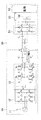
図1は本発明の一実施の形態を適用した非接触給電システム1であり、送電装置10と受電装置50とを備え、給電スタンドなどに設置される送電装置10から、車両などに搭載される受電装置50のバッテリなどの負荷53に非接触で電力を供給し、充電するシステムである。なお、図1の送電装置10及び受電装置50の詳細を図2に示す。
<< First Embodiment >>
FIG. 1 shows a non-contact
本例の送電装置10は、商用電源(東日本は周波数50Hz,西日本は周波数60Hz)の交流電源部11と、交流電源部11から送電される交流電圧を直流電圧に変換する直流電源部12と、電圧型インバータ部13と、電圧型インバータ部13から出力される高周波電力を受電装置50に非接触で供給する送電コイル(1次コイル)L1と、送電コイルL1と直列に設けられて送電装置10の共振回路を構成する1次コンデンサC2と、を備える。
The
図2に示すように、直流電源部12は、ダイオードD1とダイオードD2、ダイオードD3とダイオードD4、ダイオードD5とダイオードD6とのそれぞれが三並列に接続され、それぞれの中間接続点に交流電源部11の三相出力端子が接続されている。
As shown in FIG. 2, the DC
電圧型インバータ部13は、MOSFETなどのスイッチング素子S1〜S4のそれぞれに逆並列接続されたダイオードD7〜D10と、直流電圧の平滑コンデンサC1とから構成され、直流電源部12から出力される直流電圧を1〜50kHz程度の高周波電力に逆変換する。
The voltage
そして、スイッチング素子S1及びS2との中間接続点と、スイッチング素子S3及びS4の中間接続点のそれぞれに、送電コイルL1と1次コンデンサC2とからなる共振回路が接続されている。 Then, the intermediate connection point of the switching elements S 1 and S 2, each of the intermediate connection point of the switching elements S 3 and S 4, and the resonant circuit consisting of the power transmission coil L 1 and the primary capacitor C 2 Metropolitan is connected Yes.
受電装置50は、送電装置10の送電コイルL1から電磁誘導作用により非接触状態で高周波電力を受電する受電コイル(2次コイル)L2と、受電コイルL2に並列および直列に設けられて受電装置50の共振回路を構成する2次コンデンサC3,C4と、受電コイルL2で受電した高周波電力を整流する整流部51と、平滑コンデンサC5と、二次電池のバッテリなどからなる負荷53と、給電を遮断/導通するリレースイッチ52と、を備える。
The
整流部51は、ダイオードD11とダイオードD12、ダイオードD13とダイオードD14のそれぞれが並列に接続され、それぞれの中間接続点に、受電コイルL2と2次コンデンサC3,C4とで構成された共振回路の出力端子が接続されている。そして、整流部51の出力端子はリレースイッチ52を介して負荷53に接続されている。
In
図1に戻り、本例の非接触給電システム1は、上述した送電装置10及び受電装置50以外に、電圧型インバータ部13およびリレースイッチ52を制御する制御部14と、バッテリなどの負荷53の充電状態を監視し、充電電力の指令値を生成する負荷制御部54と、負荷制御部54にて生成した電力指令値を送電装置10に無線通信する、例えばBluetooth(登録商標)などの無線通信部55と、ユーザが充電を開始することを送電装置10に通知するための充電開始スイッチ56とを備える。
Returning to FIG. 1, the contactless
制御部14は、電圧型インバータ部13の出力電流の位相を検出する電流位相検出部15と、負荷制御部54にて生成された負荷電力指令から電圧型インバータ部13のデューティ指令Dt1,Dt2を生成するデューティ指令生成部(電圧振幅指令部)16と、デューティ指令Dt1,Dt2から電圧型インバータ部13のスイッチングパルスを生成するパルス生成部17と、を備える。
The
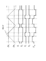
電圧型インバータ部13は、制御部14により以下のように制御される。すなわち、デューティ指令生成部16では、負荷制御部54からの負荷電力指令を受けて、負荷53に供給される電力が負荷制御部54からの指令値に一致するようなデューティ指令Dt1,Dt2を生成する。次にPWM変調を行うが、これは図3に示すように、三角波キャリア比較方式を用いて、生成されたデューティ指令Dt1,Dt2と三角波キャリアとを比較し、スイッチング素子S1〜S4の制御パルスを生成する。
The voltage
三角波キャリアの比較は以下のように行う。
スイッチング素子S1については、三角波キャリア>デューティ指令D2のとき「ON」とし、三角波キャリア≦デューティD2のとき「OFF」とする。また、スイッチング素子S2については、三角波キャリア≦デューティ指令D2のとき「ON」とし、三角波キャリア>デューティD2のとき「OFF」とする。また、スイッチング素子S3については、三角波キャリア>デューティ指令D1のとき「ON」とし、三角波キャリア≦デューティD1のとき「OFF」とする。また、スイッチング素子S4については、三角波キャリア≦デューティ指令D1のとき「ON」とし、三角波キャリア>デューティD1のとき「OFF」とする。
Comparison of triangular wave carriers is performed as follows.
The switching element S 1 is set to “ON” when triangular wave carrier> duty command D 2 , and is set to “OFF” when triangular wave carrier ≦ duty D 2 . The switching element S 2 is “ON” when triangular wave carrier ≦ duty command D 2 , and “OFF” when triangular wave carrier> duty D 2 . The switching element S 3 is “ON” when triangular wave carrier> duty command D 1 , and “OFF” when triangular wave carrier ≦ duty D 1 . The switching element S 4 is “ON” when triangular wave carrier ≦ duty command D 1 and “OFF” when triangular wave carrier> duty D 1 .
パルス生成部17はスイッチング素子S1とS3との間、および、スイッチング素子S2とS4との間がアーム短絡しないよう、デッドタイムを生成する。このようにして、図3の最下部に示すように、電圧型インバータ部13の出力線間電圧Vinvが矩形波の交流とされ、一定の電圧出力を得ることができる。
The pulse generator 17 generates a dead time so as not to cause an arm short circuit between the switching elements S1 and S3 and between the switching elements S2 and S4. In this way, as shown in the lowermost part of FIG. 3, the output line voltage Vinv of the voltage
なお、電圧型インバータ部13の制御は上述した三角波キャリア比較方式を用いる以外にも、たとえばその制御をより簡易に行うために、図4に示すように、矩形パルスを用いたデューティ50%の波形で制御することができる。
In addition to using the above-described triangular wave carrier comparison method, the voltage
さて、上述した非接触給電システム1において、たとえば給電スタンドに設置された送電装置10の送電コイルL1に対し、車両に搭載された受電装置50の受電コイルL2を接近させて給電操作を行うにあたり、受電コイルL2が送電コイルL1に充分な距離まで接近したか否か、換言すれば受電コイルL2と送電コイルL1との相対距離が所定値以下になったか否かを、車両を運転しながら判定する必要がある。受電コイルL2が送電コイルL1に対して充分な距離まで接近しないと、給電不能又は給電効率が低下するからである。
Now, in the contactless
上述した従来技術では、車両に搭載された受電コイルL2の誘起電圧のピークを検出する方法であるため、送電コイルL1と受電コイルL2との相対距離が遠いとピーク電圧が小さくなり、受電コイルL2と受電コイルL2以外の異物とを判別し難いという問題があった。 Since the above-described conventional technique is a method for detecting the peak of the induced voltage of the power receiving coil L 2 mounted on the vehicle, the peak voltage decreases when the relative distance between the power transmitting coil L 1 and the power receiving coil L 2 is long. the a receiving coil L 2 and the foreign matter other than the power receiving coil L 2 has a problem that it is difficult to determine.
このため、本例の非接触給電システム1では、受電装置50側ではなく、送電装置10側の送電コイルL1の電流状態、具体的には電圧型インバータ部13の出力電圧の位相に対する出力電流の位相の状態に基づいて、送電コイルL1に対する受電コイルL2の距離を推定する。
Therefore, the contactless
以下、図5を用いて送電装置10にて受電装置50の有無(換言すれば相対距離)を検知する方法について説明する。図5は、図1,2に示す送電装置10の電圧型インバータ部13の出力電圧位相に対する出力電流位相の周波数特性を、送電コイルL1と受電コイルL2との間の結合係数kごとに示したグラフである。
Hereinafter, a method for detecting the presence or absence (in other words, the relative distance) of the
図5によれば、送電コイルL1と受電コイルL2とが全く磁気的に結合していない状態(結合係数k=0)の場合に、周波数f0において電流位相は進み位相となる。一方、送電コイルL1と受電コイルL2とを近づけ、磁気的に結合した状態(k=0.1〜0.5)では、結合係数k=0.1以上であれば電流位相は遅れ位相となる。したがって、周波数f0で送電コイルL1を励磁し、そのときの電圧型インバータ部13の出力電流の位相が遅れ位相か進み位相かを判定することで、送電装置10だけで受電装置50の有無(換言すれば相対距離)を検知することができる。つまり、進み位相の場合は受電コイルL2が存在しないか、相対距離が給電不能な距離以上であると判断し、遅れ位相の場合は、少なくとも受電コイルL2が給電可能な距離に存在すると判断する。この場合に、図5に示すように遅れ位相の値に応じて相対距離の大小を検出することもできる。
According to FIG. 5, when a state where the power transmission coil L 1 and the power receiving coil L 2 is not at all bound magnetically (coupling coefficient k = 0), the current phase advances the phase at the frequency f 0. On the other hand, close to the power transmission coil L 1 and the power receiving coil L 2, the magnetically coupled state (k = 0.1 to 0.5), the current phase if the coupling coefficient k = 0.1 or more delayed phase It becomes. Therefore, the power transmission coil L 1 is excited at the frequency f 0 , and it is determined whether the output current phase of the voltage
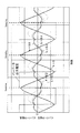
図1に示す本例の非接触給電システム1の電流位相検出部15では、上述した出力電流の位相が遅れ位相か進み位相かを、以下のようにして検出する。図6は電圧型インバータ部13の出力電圧および出力電流の時間波形を結合係数kごとに示したグラフである。同図に示すように、電圧型インバータ部13の出力電圧が負から正に切り替わるタイミングでサンプリングを行った場合に、結合係数k=0の場合に電流位相は進み位相となるため、サンプリングされた電流値は正の値となる。一方、結合係数kが0.1以上の場合に電流位相は遅れ位相となるため、サンプリングされた電流値は負の値となる。したがって、サンプリングされた電流値が正の値の場合は、受電コイルL2が存在しないか、相対距離が給電不能な距離以上であると判断する。また、サンプリングされた電流値が負の値の場合は、少なくとも受電コイルL2が給電可能な距離に存在すると判断する。
The
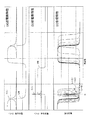
次に図7を用いて結合係数kが0.1以上となると電流位相が反転する現象について説明する。図7(a)は受電装置50を取り除き、結合係数kを0とした場合の電圧型インバータ部13の周波数に対する電流位相とゲインの特性を示している。また、図7(b)は送電装置10を取り除き、結合係数kを0とした場合の、負荷53端から見た受電コイルL2までの電流位相とゲインの特性を示している。また、図7(c)は受電装置50を含め、電圧型インバータ部13から見た電流位相の特性を結合係数kごとに示している。
Next, a phenomenon in which the current phase is reversed when the coupling coefficient k is 0.1 or more will be described with reference to FIG. FIG. 7A shows the characteristics of the current phase and the gain with respect to the frequency of the voltage
図7から理解できるように、結合係数kが0の場合においては、(a)の位相特性と(c)の位相特性は、受電装置50がない状態となるので一致する。そして、結合係数kが大きくなるにつれて、受電装置50の共振周波数であるf1付近に受電装置50の位相特性が合成された波形となる。
As can be understood from FIG. 7, when the coupling coefficient k is 0, the phase characteristics of (a) and the phase characteristics of (c) match because the
したがって、合成特性としては二次側(受電装置50)の共振周波数f1付近で結合係数kに対して大きな位相変化が起こることが理解される。このため、送電装置10の電圧型インバータ部13には、受電装置50の共振周波数f1と同じ周波数かそれに近似した周波数を励磁することが望ましい。
Therefore, it is understood that a large phase change with respect to the coupling coefficient k occurs in the vicinity of the resonance frequency f 1 on the secondary side (power receiving device 50) as a composite characteristic. For this reason, it is desirable to excite the frequency
ここで、受電装置50のQ値(共振回路の共振ピークの鋭さ)が大きいほど合成特性における共振周波数f1付近のQ値も高くなるため、受電装置50のQ値を高く設定するとよい。例えば、図1の非接触給電システム1において、受電装置50の検出を行う場合は、リレースイッチ52を開いて負荷53への給電を遮断する。これにより、受電装置50の損失成分が小さくなるのでQ値を高くすることができる。
Here, the larger the Q value of the power receiving device 50 (the sharpness of the resonance peak of the resonance circuit), the higher the Q value near the resonance frequency f 1 in the composite characteristic, so the Q value of the
なお、送電装置10の周波数特性は図7(a)のように二つの共振点を有する必要はなく、共振点は複数でも、ゼロであってもよい。したがって、送電装置10の共振コンデンサC2の構成は直列でもよく、また複数存在してもよい。さらに、受電装置50については、周波数特性において1回以上の符号変化をする特性を有する共振回路構成であれば、何回符号変化してもよい。したがって、受電装置50の共振コンデンサC3,C4の構成はひとつでもよく、直列でも並列でもよく、また複数存在してもよい。
Note that the frequency characteristics of the
次に制御フローを説明する。
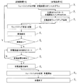
図8は、送電装置10に対して受電装置50が接近し、当該送電装置10が受電装置50の有無を検出してから負荷53の充電が終了するまでのシーケンスを示すフローチャートである。同図の左側が送電装置10の動作であり、同図の右側が受電装置50の動作を示す。なお、受電装置50については電気自動車などの移動体に受電コイルL2が装着されているものとする。
Next, the control flow will be described.
FIG. 8 is a flowchart illustrating a sequence from when the
まず、ステップS1のシャットダウン状態では、図1に示すリレースイッチ52が開となり、負荷53には電力が供給されない状態となっている。ここから充電を行うために送電装置10と受電装置50の位置合わせを開始する。電気自動車の場合であれば、電気自動車を送電装置10の上に駐車する。ここで、ユーザは充電開始スイッチ56を押す(ステップS2)。
First, in the shutdown state of step S <b> 1, the
充電開始スイッチ56が押されたら、受電装置50の無線通信部55は送電装置10を起動させるためのウェイクアップ信号を制御部14へ送信する(S3)。送電装置10は無線通信部55からのウェイクアップ信号を受信し、起動処理を実行する(ステップS4)。
When the charging
次のステップS5〜S6にて、送電装置10の送電コイルL1の上に空き缶などの金属製異物がのっていないかを、例えば金属探知装置などによって検知する。この判定の結果、送電コイルL1の上に金属製異物がのっている場合はステップS1へ戻り、リレースイッチ52の開を維持して送電装置10をシャットダウンし、ユーザに異物があることを通知する。
In the next step S5~S6, or metallic foreign matters, such as empty cans on the transmitting coil L 1 of the
送電コイルL1の上に異物がない場合はステップS7に進む。ここで、受電装置50を検出するために送電装置10の送電コイルL1に微小な電力を通電する。この結果、上述した手順で電圧型インバータ部13の電流位相に基づき受電装置50の有無を判定する。受電装置50は、ユーザが車を操作し、送電コイルL1と位置が合うまで検出ロジックを継続する。
If there is no foreign matter on the transmitting coil L 1 goes to step S7. Here, in order to detect the
ステップS9にて受電装置50が検出されたらステップS10に移行し、リレースイッチ52を閉にして充電可能状態とし、負荷53に対する充電を実行する。負荷53が二次電池などのバッテリであれば、SOCが例えば100%になったところで充電終了とする(ステップS11)。
When the
《第2実施形態》
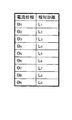
図9は本発明の他の実施の形態を適用した非接触給電システムのうちの送電装置10と受電装置50を示す電気回路図であり、その他の部分は図1と共通する。また、図10は図9に示す非接触給電システムで用いられる電流位相と相対距離との関係のルックアップテーブルの一例を示す図である。
<< Second Embodiment >>
FIG. 9 is an electric circuit diagram showing the
本例と上述した第1実施形態との差異は、図1に示すリレースイッチ52に代えて切換リレースイッチ57を設けるとともに負荷53に並列に抵抗値が既知の抵抗体58を設けた点と、図1に示す電流位相検出部15で検出された出力電流の位相に対する送電コイルL1と受電コイルL2との相対距離をテーブル化し、これを制御部14のメモリに記憶させている点である。
The difference between this example and the first embodiment described above is that a switching
図9に示す切換リレースイッチ57は、受電装置50で受電した電力が負荷53に供給され、抵抗体58には供給されない切換位置と、受電装置50で受電した電力が抵抗体58に供給され、負荷53には供給されない切換位置とのいずれかに切り換えるためのスイッチである。
In the switching
図10のルックアップテーブルは、電流位相検出部15で検出される出力電流の位相に対する、送電コイルL1と受電コイルL2との相対距離を予め実験や計算などによってテーブル化したものであり、制御部14のメモリ(図示を省略する)に記憶されている。
Look-up table of Figure 10 is for the current to the phase detector output current detected by the 15 phase was tabulated by an experiment or the like in advance and calculating the relative distance between the power transmission coil L 1 and the power receiving coil L 2, It is stored in a memory (not shown) of the
そして、図8の制御フローにおけるステップS7にて、切換リレースイッチ57を切り換えて、受電装置50に流れる電流が負荷53ではなく抵抗体58に流れるように切り換え、この状態でステップS8の処理を実行する。本例では、切換リレースイッチ57により抵抗値が既知の抵抗体58に切り換えるので、負荷53の状態に拘らず抵抗体58を用いてルックアップテーブルを作成すればよい。
Then, in step S7 in the control flow of FIG. 8, the switching
すなわち、受電装置50の有無を検出する際に負荷53に接続したまま検出処理を実行すると、負荷53の状態によって電流位相検出部15による検出値がばらつくことがあるが、本例のように抵抗値が既知の抵抗体58を用いて予めルックアップテーブルを作成しておき、実際に受電装置50を検出する際は、その抵抗体58に接続することで、検出精度がより向上する。そして、検出結果である送電コイルL1と受電コイルL2との相対距離をユーザに告知することで、ユーザの利便性が向上する。
That is, when the detection process is performed with the
なお、送電コイルL1と受電コイルL2との相対距離は、上述した出力電流の位相の正負や予め求めておいたルックアップテーブルによること以外にも、たとえば送電装置10の共振回路に出力電流の振幅を検出するセンサを設け、検出された出力電流の振幅値に基づいて判断することもできる。
The relative distance between the power transmission coil L1 and the power reception coil L2 is not limited to the above-described positive / negative phase of the output current or a lookup table obtained in advance, for example, the amplitude of the output current in the resonance circuit of the
上記実施形態によれば以下の効果を奏する。
(1)送電コイルL1と受電コイルL2と間の結合係数kが比較的低く、受電コイルL2に励磁される電圧が低い場合であっても、送電コイルL1と受電コイルL2との相対距離を検知でき、受電コイルL2の有無を高精度で検出することができる。
According to the said embodiment, there exist the following effects.
(1) Even when the coupling coefficient k between the power transmission coil L 1 and the power reception coil L 2 is relatively low and the voltage excited by the power reception coil L 2 is low, the power transmission coil L 1 and the power reception coil L 2 it can detect the relative distance, the presence or absence of the power receiving coil L 2 can be detected with high accuracy.
(2)例えば受電装置50が自動車などの移動体に搭載されている場合において、受電装置50で送電装置10の有無を検知し、通信にて送電装置10に受電装置50の有無の情報を送信する方式の場合は、受電装置50が移動中に、地上側に設置された様々な機器から発される電波や磁界を拾うことで誤作動する可能性が少なくないが、本例では、地上側に設置された送電装置10受電装置50を検出するので、誤作動が少なく信頼性が高い。
(2) For example, when the
(3)本例は受電コイルL2の電圧を検出する方式ではないため、受電コイルL2の電圧を検出して受電コイルL2の有無を判定する方式の場合に必要とされるピーク電圧の検出手段やデータ処理手段が不要である。したがって、装置のコストを低減できる。 (3) This example is not a method of detecting the voltage of the power reception coil L 2, the peak voltage required in the case of determining scheme whether the receiving coil L 2 by detecting the voltage of the power reception coil L 2 Detection means and data processing means are unnecessary. Therefore, the cost of the apparatus can be reduced.
(4)本例において、受電装置50の共振周波数と送電装置10の電圧型インバータ部13の励磁周波数を一致させれば、受電コイルL2と送電コイルL1とが接近し、結合係数kが0以外の状態になった場合に、送電装置10の電圧型インバータ部13の出力電圧の位相に対する出力電流の位相の変化が大きくなる。したがって、その変化を検知することが容易になり、精度よく受電装置50を検出することができる。
(4) In this example, if the resonance frequency of the
(5)本例において、結合係数kが0かそれ以外かによって、電流位相が進み位相から遅れ位相に反転するため、電流位相の符号を判定することで受電装置50の有無を高精度に検出できる。
(5) In this example, since the current phase is reversed from the leading phase to the lagging phase depending on whether the coupling coefficient k is 0 or not, the presence or absence of the
(6)本例において、送電側コイルL1と受電側コイルL2との相対距離に応じた電流位相の変化特性を予め実験や計算などでテーブル化し、メモリに保存しておけば、受電装置50と送電装置10との相対位置をユーザに告知することができ、利便性が向上する。
(6) In this example, if the change characteristics of the current phase according to the relative distance between the power transmission side coil L1 and the power reception side coil L2 are tabulated in advance by experiment or calculation and stored in a memory, The user can be notified of the relative position with respect to the
(7)本例において、出力電流の振幅を検出し、検出された電流振幅値により受電装置50の有無を検出すれば、送電装置10のインバータ部13を、電圧・電流の位相の検知機能を持たない安価なコントローラで制御できるので、制御部14を安価に構成できる。
(7) In this example, if the amplitude of the output current is detected and the presence / absence of the
(8)本例において、受電装置50の有無を検出する際に受電装置50の負荷53を遮断すれば、受電装置50の損失成分を小さくすることができ、Q値を高めることができる。これにより検出精度がより高くなる。
(9)また本例において、受電装置50の負荷53を切り換えて、受電装置50のQ値を可変すれば、送電装置10のインバータ部13の出力電圧の位相に対する出力電流の位相の変化が大きくなる。したがって、受電コイルL2と送電コイルL1とが接近して、結合係数kが0以外の状態になったことを検出する精度がより向上する。
(8) In this example, if the
(9) Further, in this example, if the
(10)本例において、受電装置50の有無を検出する際は受電装置50の負荷53を抵抗値が既知の抵抗体58に切り換え、受電装置50のQ値を常に一定とすることで、送電コイルL1と受電コイルL2との相対距離に応じた位相変化特性を予め実験や計算などでテーブル化し、メモリに保存しておくことができる。これにより、受電コイルL2と送電コイルL1との相対位置をユーザに告知することができるため利便性が向上する。
(10) In this example, when detecting the presence / absence of the
なお、上述した実施形態は電磁誘導による非接触給電方式を説明したが、電磁場の共鳴による磁気的結合を利用した非接触給電方式を適用することもできる。 In the above-described embodiment, the non-contact power feeding method using electromagnetic induction has been described. However, a non-contact power feeding method using magnetic coupling by resonance of an electromagnetic field can be applied.
上記電流位相検出部15は本発明に係る検出手段及び推定手段に相当し、上記電圧型インバータ部13は本発明に係る電力変換器に相当し、上記リレースイッチ52は本発明に係る入切手段に相当し、上記切換リレースイッチ57は本発明に係る切換手段に相当する。
The current
1…非接触給電システム
10…送電装置
11…交流電源部
12…直流電源部
13…電圧型インバータ部
D1〜D10…ダイオード
C1,C2…コンデンサ
S1〜S4…MOSFET
L1…送電コイル
14…制御部
15…電流位相検出部
16…デューティ指令生成部
17…パルス生成部
50…受電装置
L2…受電コイル
D11〜D14…ダイオード
C3〜C5…コンデンサ
51…整流部
52…リレースイッチ
53…負荷
54…負荷制御部
55…無線通信部
56…充電開始スイッチ
57…切換リレースイッチ
58…抵抗負荷
1 ... non-contact
L 1 ...
Claims (12)
前記送電装置は、
通電される送電コイルと、
前記送電コイルの電流状態を検出する検出手段と、
検出された電流状態の変化から、前記送電装置と前記受電装置との相対距離を推定する推定手段と、を備えることを特徴とする非接触給電装置。 A non-contact power feeding device including a power transmitting device that transmits current by at least magnetic coupling to a power receiving device,
The power transmission device is:
A power transmission coil to be energized;
Detecting means for detecting a current state of the power transmission coil;
A non-contact power feeding device comprising: an estimation unit configured to estimate a relative distance between the power transmission device and the power reception device from a detected change in a current state.
前記送電コイルに通電する電力変換器をさらに備え、
前記検出手段は、前記電力変換器の出力電圧の位相に対する出力電流の位相を検出し、
前記推定手段は、検出された出力電流の位相に基づいて前記相対距離を推定することを特徴とする非接触給電装置。 The contactless power supply device according to claim 1,
A power converter for energizing the power transmission coil;
The detection means detects the phase of the output current with respect to the phase of the output voltage of the power converter,
The non-contact power feeding apparatus according to claim 1, wherein the estimating means estimates the relative distance based on the detected phase of the output current.
前記電力変換器の励磁周波数は、前記受電装置の共振周波数と同じ周波数に設定されていることを特徴とする非接触給電装置。 In the non-contact electric power feeder of Claim 2,
The contactless power feeding device according to claim 1, wherein an excitation frequency of the power converter is set to the same frequency as a resonance frequency of the power receiving device.
前記推定手段は、検出された出力電流の位相が正の値か負の値かに応じて、前記相対距離を推定することを特徴とする非接触給電装置。 In the non-contact electric power feeder of Claim 2 or 3,
The non-contact power feeding apparatus according to claim 1, wherein the estimating means estimates the relative distance according to whether the phase of the detected output current is a positive value or a negative value.
前記相対距離と前記出力電流の位相との関係を示すルックアップテーブルが記憶された記憶手段をさらに備え、
前記推定手段は、検出された出力電流の位相と前記ルックアップテーブルとに基づいて前記相対距離を推定することを特徴とする非接触給電装置。 In the non-contact electric power feeder of Claim 2 or 3,
A storage unit storing a lookup table indicating a relationship between the relative distance and the phase of the output current;
The non-contact power feeding apparatus according to claim 1, wherein the estimating means estimates the relative distance based on the detected phase of the output current and the lookup table.
前記検出手段は、前記出力電流の振幅を検出し、
前記推定手段は、検出された出力電流の振幅に基づいて前記相対距離を推定することを特徴とする非接触給電装置。 In the non-contact electric power feeder of Claim 2 or 3,
The detecting means detects an amplitude of the output current;
The non-contact power feeding apparatus, wherein the estimating means estimates the relative distance based on the detected amplitude of the output current.
前記送電装置は、
通電される送電コイルと、
前記送電コイルの電流状態を検出する検出手段と、
検出された電流状態の変化から、前記送電装置と前記受電装置との相対距離を推定する推定手段と、を備え、
前記受電装置は、
少なくとも一つの共振周波数を有し、前記送電コイルから送信される電流を受電する受電コイルを備えることを特徴とする非接触給電装置。 A non-contact power feeding device that transmits current from a power transmission device to a power receiving device by at least magnetic coupling,
The power transmission device is:
A power transmission coil to be energized;
Detecting means for detecting a current state of the power transmission coil;
An estimation means for estimating a relative distance between the power transmission device and the power reception device from the detected change in the current state,
The power receiving device is:
A non-contact power feeding apparatus comprising a power receiving coil having at least one resonance frequency and receiving a current transmitted from the power transmitting coil.
前記送電装置は、前記送電コイルに通電する電力変換器をさらに備え、
前記電力変換器の励磁周波数は、前記受電コイルの共振周波数と同じ周波数に設定されていることを特徴とする非接触給電装置。 In the non-contact electric power feeder of Claim 7,
The power transmission device further includes a power converter for energizing the power transmission coil,
The contactless power feeding device according to claim 1, wherein an excitation frequency of the power converter is set to the same frequency as a resonance frequency of the power receiving coil.
前記受電装置は、受電した電力を当該受電装置に接続される電力負荷に供給又は遮断する入切手段を備えることを特徴とする非接触給電装置。 In the non-contact electric power feeder of Claim 7 or 8,
The non-contact power feeding device, wherein the power receiving device includes on / off means for supplying or cutting off the received power to a power load connected to the power receiving device.
前記受電装置は、受電した電力を当該受電装置に接続される電力負荷と当該受電装置に設けられた所定の電力負荷とのいずれかに切り換える切換手段を備えることを特徴とする非接触給電装置。 In the non-contact electric power feeder of Claim 7 or 8,
The power receiving apparatus includes a switching unit that switches received power between a power load connected to the power receiving apparatus and a predetermined power load provided in the power receiving apparatus.
前記所定の電力負荷は、所定の抵抗値を有する抵抗体であることを特徴とする非接触給電装置。 The contactless power supply device according to claim 10,
The non-contact power feeding apparatus according to claim 1, wherein the predetermined power load is a resistor having a predetermined resistance value.
前記送電装置の送電コイルの電流状態を検出するステップと、
検出された電流状態の変化から、前記送電装置と前記受電装置との相対距離を推定するステップと、を有する非接触給電方法。 A non-contact power feeding method for transmitting a current from a power transmission device to a power reception device by at least magnetic coupling,
Detecting a current state of a power transmission coil of the power transmission device;
And a step of estimating a relative distance between the power transmitting device and the power receiving device from the detected change in the current state.
Priority Applications (1)
| Application Number | Priority Date | Filing Date | Title |
|---|---|---|---|
| JP2010137932A JP2012005238A (en) | 2010-06-17 | 2010-06-17 | Non-contact power feeding device |
Applications Claiming Priority (1)
| Application Number | Priority Date | Filing Date | Title |
|---|---|---|---|
| JP2010137932A JP2012005238A (en) | 2010-06-17 | 2010-06-17 | Non-contact power feeding device |
Publications (1)
| Publication Number | Publication Date |
|---|---|
| JP2012005238A true JP2012005238A (en) | 2012-01-05 |
Family
ID=45536583
Family Applications (1)
| Application Number | Title | Priority Date | Filing Date |
|---|---|---|---|
| JP2010137932A Pending JP2012005238A (en) | 2010-06-17 | 2010-06-17 | Non-contact power feeding device |
Country Status (1)
| Country | Link |
|---|---|
| JP (1) | JP2012005238A (en) |
Cited By (20)
| Publication number | Priority date | Publication date | Assignee | Title |
|---|---|---|---|---|
| WO2013111307A1 (en) * | 2012-01-26 | 2013-08-01 | パイオニア株式会社 | Power transmitting apparatus and power transmitting method |
| WO2013179763A1 (en) * | 2012-05-31 | 2013-12-05 | 日産自動車株式会社 | Non-contact power feed device and non-contact power feed method |
| WO2014087823A1 (en) | 2012-12-03 | 2014-06-12 | 日産自動車株式会社 | Non-contact power supply apparatus, non-contact power supply system, and non-contact power supply method |
| KR20140087612A (en) * | 2012-12-31 | 2014-07-09 | 주식회사 한림포스텍 | Method for controlling wireless power transmission in resonat wireless power transmission system, wireless power transmitting apparatus using the same, and wireless power receiving apparatus using the same |
| WO2014171255A1 (en) * | 2013-04-15 | 2014-10-23 | 日産自動車株式会社 | Contactless power supply system |
| KR101438887B1 (en) * | 2012-05-25 | 2014-11-03 | 엘지이노텍 주식회사 | Wireless power transmission device, power supplying device and power control method thereof |
| JP2015008618A (en) * | 2013-06-26 | 2015-01-15 | キヤノン株式会社 | Power transmitting device, method for controlling power transmitting device, and program |
| JP2016019375A (en) * | 2014-07-09 | 2016-02-01 | 株式会社デンソー | Power converter |
| WO2016051484A1 (en) * | 2014-09-30 | 2016-04-07 | 富士機械製造株式会社 | Non-contact power feeding device |
| JP2016163493A (en) * | 2015-03-04 | 2016-09-05 | ローム株式会社 | Wireless power-transmitting device, foreign matter detection method, battery charger |
| EP3066737A1 (en) * | 2013-10-09 | 2016-09-14 | Apple Inc. | Reducing power dissipation in inductive energy transfer systems |
| JP2016537908A (en) * | 2013-09-10 | 2016-12-01 | エフィシエント パワー コンヴァーション コーポレーション | High efficiency voltage mode class D topology |
| JP2017184583A (en) * | 2016-03-31 | 2017-10-05 | 東洋電機製造株式会社 | Wireless power transmission system |
| WO2017183572A1 (en) * | 2016-04-20 | 2017-10-26 | ヤマハ発動機株式会社 | Wireless power supply device |
| US10122217B2 (en) | 2015-09-28 | 2018-11-06 | Apple Inc. | In-band signaling within wireless power transfer systems |
| US10305334B2 (en) | 2014-05-30 | 2019-05-28 | Ihi Corporation | Wireless power-supplying system, power-receiving device, and power-transmitting device |
| US10404235B2 (en) | 2013-11-21 | 2019-09-03 | Apple Inc. | Using pulsed biases to represent DC bias for charging |
| US10601250B1 (en) | 2016-09-22 | 2020-03-24 | Apple Inc. | Asymmetric duty control of a half bridge power converter |
| US10978899B2 (en) | 2017-02-02 | 2021-04-13 | Apple Inc. | Wireless charging system with duty cycle control |
| JP6906712B1 (en) * | 2020-04-22 | 2021-07-21 | 三菱電機株式会社 | Power transmission equipment and wireless power transmission system |
-
2010
- 2010-06-17 JP JP2010137932A patent/JP2012005238A/en active Pending
Cited By (41)
| Publication number | Priority date | Publication date | Assignee | Title |
|---|---|---|---|---|
| JPWO2013111307A1 (en) * | 2012-01-26 | 2015-05-11 | パイオニア株式会社 | Power transmission device and power transmission method |
| WO2013111307A1 (en) * | 2012-01-26 | 2013-08-01 | パイオニア株式会社 | Power transmitting apparatus and power transmitting method |
| US9773609B2 (en) | 2012-05-25 | 2017-09-26 | Lg Innotek Co., Ltd. | Power supply apparatus and power control method thereof |
| KR101438887B1 (en) * | 2012-05-25 | 2014-11-03 | 엘지이노텍 주식회사 | Wireless power transmission device, power supplying device and power control method thereof |
| WO2013179763A1 (en) * | 2012-05-31 | 2013-12-05 | 日産自動車株式会社 | Non-contact power feed device and non-contact power feed method |
| JP2013251974A (en) * | 2012-05-31 | 2013-12-12 | Nissan Motor Co Ltd | Non-contact power supply device |
| WO2014087823A1 (en) | 2012-12-03 | 2014-06-12 | 日産自動車株式会社 | Non-contact power supply apparatus, non-contact power supply system, and non-contact power supply method |
| US9446675B2 (en) | 2012-12-03 | 2016-09-20 | Nissan Motor Co., Ltd. | Non-contact power supply apparatus, non-contact power supply system, and non-contact power supply method |
| JP2016506229A (en) * | 2012-12-31 | 2016-02-25 | ハンリム ポステック カンパニー リミテッド | Wireless power transmission control method in resonance type wireless power transmission system, wireless power transmitting apparatus using the same, and wireless power receiving apparatus using the same |
| JP7026646B2 (en) | 2012-12-31 | 2022-02-28 | ジーイー・ハイブリッド・テクノロジーズ・エルエルシー | A wireless power transmission control method in a resonance type wireless power transmission system, a wireless power transmission device using the same, and a wireless power receiving device using the same. |
| JP2019083683A (en) * | 2012-12-31 | 2019-05-30 | ジーイー・ハイブリッド・テクノロジーズ・エルエルシー | Wireless power transmission control method in resonance type wireless power transmission system, wireless power transmission apparatus using the same and wireless power receiver using the same |
| KR20140087612A (en) * | 2012-12-31 | 2014-07-09 | 주식회사 한림포스텍 | Method for controlling wireless power transmission in resonat wireless power transmission system, wireless power transmitting apparatus using the same, and wireless power receiving apparatus using the same |
| KR102004541B1 (en) * | 2012-12-31 | 2019-07-26 | 지이 하이브리드 테크놀로지스, 엘엘씨 | Method for controlling wireless power transmission in resonat wireless power transmission system, wireless power transmitting apparatus using the same, and wireless power receiving apparatus using the same |
| WO2014171255A1 (en) * | 2013-04-15 | 2014-10-23 | 日産自動車株式会社 | Contactless power supply system |
| JP6036995B2 (en) * | 2013-04-15 | 2016-11-30 | 日産自動車株式会社 | Contactless power supply system |
| JPWO2014171255A1 (en) * | 2013-04-15 | 2017-02-23 | 日産自動車株式会社 | Contactless power supply system |
| US9537323B2 (en) | 2013-04-15 | 2017-01-03 | Nissan Motor Co., Ltd. | Contactless power supplying system with power limiting control |
| CN105122590A (en) * | 2013-04-15 | 2015-12-02 | 日产自动车株式会社 | Contactless power supply system |
| US9941750B2 (en) | 2013-06-26 | 2018-04-10 | Canon Kabushiki Kaisha | Power transmitting apparatus, control method for power transmitting apparatus, and recording medium storing program |
| US10581280B2 (en) | 2013-06-26 | 2020-03-03 | Canon Kabushiki Kaisha | Power transmitting apparatus, control method for power transmitting apparatus, and recording medium storing program |
| CN105359380A (en) * | 2013-06-26 | 2016-02-24 | 佳能株式会社 | Power transmitting apparatus, control method for power transmitting apparatus, and recording medium storing program |
| JP2015008618A (en) * | 2013-06-26 | 2015-01-15 | キヤノン株式会社 | Power transmitting device, method for controlling power transmitting device, and program |
| JP2016537908A (en) * | 2013-09-10 | 2016-12-01 | エフィシエント パワー コンヴァーション コーポレーション | High efficiency voltage mode class D topology |
| JP2016538811A (en) * | 2013-10-09 | 2016-12-08 | アップル インコーポレイテッド | Reduction of power dissipation in inductive energy transmission systems. |
| EP3066737A1 (en) * | 2013-10-09 | 2016-09-14 | Apple Inc. | Reducing power dissipation in inductive energy transfer systems |
| US10404235B2 (en) | 2013-11-21 | 2019-09-03 | Apple Inc. | Using pulsed biases to represent DC bias for charging |
| US10305334B2 (en) | 2014-05-30 | 2019-05-28 | Ihi Corporation | Wireless power-supplying system, power-receiving device, and power-transmitting device |
| JP2016019375A (en) * | 2014-07-09 | 2016-02-01 | 株式会社デンソー | Power converter |
| JPWO2016051484A1 (en) * | 2014-09-30 | 2017-07-13 | 富士機械製造株式会社 | Non-contact power feeding device |
| WO2016051484A1 (en) * | 2014-09-30 | 2016-04-07 | 富士機械製造株式会社 | Non-contact power feeding device |
| CN107408847B (en) * | 2015-03-04 | 2020-11-10 | 罗姆股份有限公司 | Wireless power supply device, foreign matter detection method, and charger |
| US10291078B2 (en) | 2015-03-04 | 2019-05-14 | Rohm Co., Ltd. | Wireless power transmitter |
| WO2016140004A1 (en) * | 2015-03-04 | 2016-09-09 | ローム株式会社 | Wireless power transmission device, foreign material detection method, and charger |
| JP2016163493A (en) * | 2015-03-04 | 2016-09-05 | ローム株式会社 | Wireless power-transmitting device, foreign matter detection method, battery charger |
| CN107408847A (en) * | 2015-03-04 | 2017-11-28 | 罗姆股份有限公司 | Wireless power supply, foreign matter detecting method, charger |
| US10122217B2 (en) | 2015-09-28 | 2018-11-06 | Apple Inc. | In-band signaling within wireless power transfer systems |
| JP2017184583A (en) * | 2016-03-31 | 2017-10-05 | 東洋電機製造株式会社 | Wireless power transmission system |
| WO2017183572A1 (en) * | 2016-04-20 | 2017-10-26 | ヤマハ発動機株式会社 | Wireless power supply device |
| US10601250B1 (en) | 2016-09-22 | 2020-03-24 | Apple Inc. | Asymmetric duty control of a half bridge power converter |
| US10978899B2 (en) | 2017-02-02 | 2021-04-13 | Apple Inc. | Wireless charging system with duty cycle control |
| JP6906712B1 (en) * | 2020-04-22 | 2021-07-21 | 三菱電機株式会社 | Power transmission equipment and wireless power transmission system |
Similar Documents
| Publication | Publication Date | Title |
|---|---|---|
| JP2012005238A (en) | Non-contact power feeding device | |
| KR101560964B1 (en) | Contactless electricity supply device | |
| US11175428B2 (en) | Metallic foreign object detector, wireless power transmitting device, wireless power receiving device, and wireless power transmission system | |
| CN108400641B (en) | Non-contact power transmission device | |
| US10170942B2 (en) | Power receiving device and wireless power transmission system | |
| US10277082B2 (en) | Power-transmitting device and wireless power-supplying system | |
| US20140103711A1 (en) | Contactless power receiving device, vehicle equipped with the same, contactless power transmitting device, and contactless power transfer system | |
| EP3157116A1 (en) | Contactless power-supplying system, power-receiving device, and power-transmitting device | |
| US10256675B2 (en) | Power-supplying device and wireless power supply system | |
| JP6187384B2 (en) | Power transmission equipment | |
| CN103477535A (en) | Power transmitting system | |
| US9722463B2 (en) | Wireless power transmitter and wireless power transmission method | |
| US10218212B2 (en) | System and apparatus for inductive charging of a handheld device | |
| JP5761508B2 (en) | Power transmission system | |
| US11322985B2 (en) | Wireless power transfer system, power transmission apparatus, and power reception apparatus | |
| WO2012098867A1 (en) | Power supply device for non-contact charging device | |
| JP2019047675A (en) | Power supply system | |
| CN104821637A (en) | Non-contact electric power transmission system and charging station | |
| JP2015216739A (en) | Power transmission apparatus | |
| JP2000197275A (en) | Controller of non-contacting charger | |
| US11652368B2 (en) | Non-contact power supply device and power transmission device | |
| JP2014110681A (en) | Non-contact power supply device, non-contact power supply system, and non-contact power supply method | |
| JP2014117017A (en) | Power supply system | |
| JP2017127091A (en) | Non-contact power transmission apparatus and non-contact power transmission system | |
| JP5761507B2 (en) | Power transmission system |