JP2012003022A - Stereoscopic imaging optical system, interchangeable lens device, and camera system - Google Patents
Stereoscopic imaging optical system, interchangeable lens device, and camera system Download PDFInfo
- Publication number
- JP2012003022A JP2012003022A JP2010137685A JP2010137685A JP2012003022A JP 2012003022 A JP2012003022 A JP 2012003022A JP 2010137685 A JP2010137685 A JP 2010137685A JP 2010137685 A JP2010137685 A JP 2010137685A JP 2012003022 A JP2012003022 A JP 2012003022A
- Authority
- JP
- Japan
- Prior art keywords
- lens
- image
- imaging
- optical system
- imaging optical
- Prior art date
- Legal status (The legal status is an assumption and is not a legal conclusion. Google has not performed a legal analysis and makes no representation as to the accuracy of the status listed.)
- Pending
Links
Images


Classifications
-
- G—PHYSICS
- G03—PHOTOGRAPHY; CINEMATOGRAPHY; ANALOGOUS TECHNIQUES USING WAVES OTHER THAN OPTICAL WAVES; ELECTROGRAPHY; HOLOGRAPHY
- G03B—APPARATUS OR ARRANGEMENTS FOR TAKING PHOTOGRAPHS OR FOR PROJECTING OR VIEWING THEM; APPARATUS OR ARRANGEMENTS EMPLOYING ANALOGOUS TECHNIQUES USING WAVES OTHER THAN OPTICAL WAVES; ACCESSORIES THEREFOR
- G03B17/00—Details of cameras or camera bodies; Accessories therefor
- G03B17/02—Bodies
- G03B17/12—Bodies with means for supporting objectives, supplementary lenses, filters, masks, or turrets
- G03B17/14—Bodies with means for supporting objectives, supplementary lenses, filters, masks, or turrets interchangeably
-
- G—PHYSICS
- G03—PHOTOGRAPHY; CINEMATOGRAPHY; ANALOGOUS TECHNIQUES USING WAVES OTHER THAN OPTICAL WAVES; ELECTROGRAPHY; HOLOGRAPHY
- G03B—APPARATUS OR ARRANGEMENTS FOR TAKING PHOTOGRAPHS OR FOR PROJECTING OR VIEWING THEM; APPARATUS OR ARRANGEMENTS EMPLOYING ANALOGOUS TECHNIQUES USING WAVES OTHER THAN OPTICAL WAVES; ACCESSORIES THEREFOR
- G03B35/00—Stereoscopic photography
- G03B35/08—Stereoscopic photography by simultaneous recording
- G03B35/10—Stereoscopic photography by simultaneous recording having single camera with stereoscopic-base-defining system
-
- H—ELECTRICITY
- H04—ELECTRIC COMMUNICATION TECHNIQUE
- H04N—PICTORIAL COMMUNICATION, e.g. TELEVISION
- H04N13/00—Stereoscopic video systems; Multi-view video systems; Details thereof
- H04N13/20—Image signal generators
- H04N13/204—Image signal generators using stereoscopic image cameras
- H04N13/207—Image signal generators using stereoscopic image cameras using a single 2D image sensor
- H04N13/218—Image signal generators using stereoscopic image cameras using a single 2D image sensor using spatial multiplexing
-
- H—ELECTRICITY
- H04—ELECTRIC COMMUNICATION TECHNIQUE
- H04N—PICTORIAL COMMUNICATION, e.g. TELEVISION
- H04N13/00—Stereoscopic video systems; Multi-view video systems; Details thereof
- H04N13/20—Image signal generators
- H04N13/286—Image signal generators having separate monoscopic and stereoscopic modes
Landscapes
- Engineering & Computer Science (AREA)
- Multimedia (AREA)
- Signal Processing (AREA)
- Physics & Mathematics (AREA)
- General Physics & Mathematics (AREA)
- Stereoscopic And Panoramic Photography (AREA)
- Lenses (AREA)
- Testing, Inspecting, Measuring Of Stereoscopic Televisions And Televisions (AREA)
- Cameras In General (AREA)
- Structure And Mechanism Of Cameras (AREA)
Abstract
Description
本発明は、3次元画像の撮像に用いられる立体撮像光学系、これを用いた交換レンズ装置及びカメラシステムに関する。 The present invention relates to a stereoscopic imaging optical system used for imaging a three-dimensional image, an interchangeable lens apparatus using the same, and a camera system.
近年、3次元画像を表示可能な表示装置が脚光を浴びている。3次元画像の再現方法としては、原理の異なるいくつかのものが知られているが、左右の目に視差のある画像を提示することによって、立体画像を知覚させる手法が現在主流である。3次元画像を再現するための画像は、左右の角度差(視差)のある一対の画像を同時に形成可能な光学系を用いて撮像される(例えば、特許文献1及び2参照)。
In recent years, display devices capable of displaying a three-dimensional image have attracted attention. There are several known three-dimensional image reproduction methods, but a method of perceiving a stereoscopic image by presenting an image with parallax between the left and right eyes is currently the mainstream. An image for reproducing a three-dimensional image is picked up using an optical system that can simultaneously form a pair of images having a left-right angular difference (parallax) (see, for example,
特許文献1には、一対の像形成レンズと複数のミラーとを用いて、フィルム面上に視差のある画像を並べて結像できる光学系が記載されている。
特許文献2には、一対のレンズと複数のミラーとの配置を変更することによって、2次元画像および3次元画像の両方を撮影できるカメラが記載されている。
上記の特許文献1に記載の光学系では、フィルムの現像後に得られる写真を立体視できるようにするため、ミラーを用いて左右の画像を入れ替えている。しかしながら、ミラーを複数用いることによって、光学系の構成が複雑化し、構成サイズも大きくなってしまう。また、特許文献1のように、一対のレンズを並列に配置した場合、それぞれのレンズによって形成される像同士が干渉するという問題が生じる。
In the optical system described in
上記の特許文献2に記載のカメラでは、視差画像の撮影時には、カメラ内に設けられる移動式の隔壁を用いて、一対のレンズによって形成される像同士の干渉を防止している。ただし、このような隔壁は、レンズと本体とが一体型のカメラには適用可能性があるが、最近人気のあるレンズ交換式デジタルカメラシステムには適用が困難である。何故なら、レンズ交換式デジタルカメラの本体内にある撮像素子の近傍には、ローパスフィルタ、手振れ補正機構、ゴミ取り機構などが配置されており、更に隔壁のような構造物を配置するスペースを確保できないからである。
In the camera described in
それ故に、本発明は、矩形状の1つの撮像素子上に、相互に干渉のない2つの光学像を並べて形成することができ、レンズ交換式デジタルカメラシステムにも適用可能な立体撮像光学系、並びに、これを備えた交換レンズ装置及びカメラシステムを提供することを目的とする。 Therefore, the present invention can form a two-dimensional image pickup optical system that can form two optical images without interference with each other on a single rectangular image pickup element, and can also be applied to an interchangeable lens digital camera system, It is another object of the present invention to provide an interchangeable lens apparatus and a camera system provided with the same.
本発明に係る立体撮像光学系は、第1及び第2の撮像領域のそれぞれに被写体の光学像を形成するものであって、第1の撮像領域に被写体の光学像を形成する第1のレンズ系と、第1のレンズ系と並列に配置され、第2の撮像領域に被写体の光学像を形成する第2のレンズ系と、第1及び第2のレンズ系の物体側に配置される視野絞りとを備える。第1及び第2のレンズ系は、各々によって形成される像円が第1及び第2の撮像領域の両方と重なり合うような位置関係に配置されている。視野絞りは、第1の撮像領域に対して第2の撮像領域と反対側の領域に入射する光束と、第2の撮像領域に対して第1の撮像領域と反対側の領域に入射する光束とを遮光せず、第1のレンズ系から第2の撮像領域に入射する光束と、第2のレンズ系から第1の撮像領域に入射する光束とを遮光する。 The stereoscopic imaging optical system according to the present invention forms an optical image of a subject in each of the first and second imaging regions, and the first lens forms an optical image of the subject in the first imaging region. A system, a second lens system arranged in parallel with the first lens system, and forming an optical image of the subject in the second imaging region, and a field of view arranged on the object side of the first and second lens systems A diaphragm. The first and second lens systems are arranged in a positional relationship such that an image circle formed by each overlaps both the first and second imaging regions. The field stop includes a light beam incident on a region opposite to the second imaging region with respect to the first imaging region, and a light beam incident on a region opposite to the first imaging region with respect to the second imaging region. Are shielded from light, and the light beam incident on the second imaging region from the first lens system and the light beam incident on the first imaging region from the second lens system are shielded.
また、本発明に係る交換レンズ装置は、撮像素子を内蔵するカメラ本体に着脱自在に取り付けられるものであり、上記の立体撮像光学系と、カメラ本体のカメラマウント部に接続可能なレンズマウント部とを備える。 Further, an interchangeable lens device according to the present invention is detachably attached to a camera body incorporating an image sensor, and includes the above-described stereoscopic imaging optical system and a lens mount portion connectable to the camera mount portion of the camera body. Is provided.
本発明によれば、視野絞りによって、撮像素子上に形成される一対の像同士の干渉を抑制できる。視野絞りは、第1及び第2のレンズ系の物体側に設けられるので、本発明に係る立体撮像光学系は、レンズ交換式デジタルカメラシステムにも適用が容易である。 According to the present invention, interference between a pair of images formed on the image sensor can be suppressed by the field stop. Since the field stop is provided on the object side of the first and second lens systems, the stereoscopic imaging optical system according to the present invention can be easily applied to an interchangeable lens digital camera system.
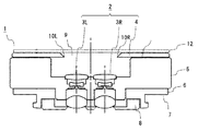
図1は、本発明の立体撮像光学系を備える交換レンズ装置の断面図であり、図2は、本発明の立体撮像光学系の正面図である。 FIG. 1 is a cross-sectional view of an interchangeable lens apparatus including the stereoscopic imaging optical system of the present invention, and FIG. 2 is a front view of the stereoscopic imaging optical system of the present invention.
交換レンズ装置1は、レンズ交換式デジタルカメラシステムのカメラ本体に着脱自在に取り付けられ、3次元画像(静止画・動画の両方を含む)を再現するための角度差のある画像を撮像するために用いられる。交換レンズ装置1は、立体撮像光学系2と、鏡筒5と、カメラ本体のカメラマウント部に着脱自在のレンズマウント部6と、保護部材8と、最前面に配置されるガラス板12とを備える。レンズマウント部6は、カメラマウント部に面接触するマウント面7を有する。
The
立体撮像光学系2は、一対のレンズ系3R及び3Lと、レンズ系3R及び3Lの物体側に配置される視野絞り4とを備える。
The stereoscopic imaging
レンズ系3R及び3Lは、同一のレンズ構成を有し、各々の光軸が互いに平行となるように並列に配置されている。レンズ系3R及び3Lは、交換レンズ装置1をカメラ本体に取り付けた際に、カメラ本体の左右方向(撮像素子の長手方向)に整列する。そして、レンズ系3Rは、撮像素子の右半分の撮像領域に被写体の光学像を結像し、レンズ系3Lは、撮像素子の左半分の撮像領域に被写体の光学像を結像する。レンズ系3R及び3Lの光軸同士の間隔は、左右の撮影画像に所定の視差が生じるように設定されている。また、レンズ系3R及び3Lと撮像素子とは、レンズ系3Rによって撮像素子上に形成される像円と、レンズ系3Lによって撮像素子上に形成される像円とが、撮像素子の中央部分で重なり合うような位置関係に配置されている。
The
レンズ系3R及び3Lの各々は、複数のレンズ素子から構成されている。一部のレンズ素子は、レンズマウント部6のマウント面7より像側に突出するように配置されている。ここで、レンズ素子が「マウント面より像側に突出する」とは、レンズ素子の少なくとも一部がマウント面を含む平面より像側に位置していることを言う。図1の例では、レンズ3R及び3L内で最も像側に配置される合計4枚のレンズ素子がマウント面7より像側に突出している。尚、レンズ系3R及び3Lのレンズ構成の詳細は後述する。
Each of the
マウント面より像側に突出した状態でレンズ素子を配置することによって、レンズ光学系内の絞りをレンズ主点よりも物体側に移動させることができる。また、マウント面7から突出するレンズ素子を保持する鏡筒の一部で、絞りより物体側から入る迷光をカットすることができる。
By disposing the lens element in a state of projecting from the mount surface to the image side, the diaphragm in the lens optical system can be moved to the object side from the lens principal point. Further, stray light entering from the object side from the stop can be cut by a part of the lens barrel holding the lens element protruding from the
視野絞り4は、1つの開口9を有する部材によって構成されている。開口9は、レンズ系3R及び3Lの物体側に位置しており、開口を構成する周縁の一部に、撮像素子の撮像面を左右に二分する中央線と同方向(図2の上下方向)に延びる直線状の一対のエッジ10R及び10Lを有する。これらのエッジ10R及び10Lによって、撮像素子の中央に入射する光束の一部が遮光される。この視野絞り4による入射光の遮光の詳細は後述する。
The
鏡筒5は、ほぼ円筒形状を有し、その中央部分にレンズ素子3R及び3Lを保持する。鏡筒5の前面部分に視野絞り4が取り付けられ、後面部分にレンズマウント部6が設けられている。保護部材8は、レンズマウント部6のマウント面7より像側に突出するレンズ素子を保護するために設けられている。また、最前面のガラス板12は、レンズ系3R及び3Lの保護と、鏡筒5内への埃やゴミの侵入防止のために設けられている。
The
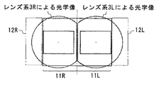
ここで、1つの撮像素子で左右の画像を撮像する場合を例として、視野絞り4の機能の詳細を説明する。以下の説明では、撮像面の右半分を撮像領域11Rといい、撮像面の左半分を領域11Lという。
Here, the details of the function of the
図3は、視野絞りのない立体撮像光学系によって撮像素子上に形成される光学像を示す参考図である。 FIG. 3 is a reference diagram showing an optical image formed on an image sensor by a stereoscopic imaging optical system without a field stop.
並列に配置した2つのレンズ系のみを用いて、1つの撮像素子上の撮像領域11R及び撮像領域11Lに2つの画像を並べて形成する場合、撮像素子の中央部分で左右の像同士が混ざり合ったり、右側のレンズ系からの迷光が左側の撮像領域に入ったりする(もしくは、左側のレンズ系からの迷光が右側の撮像領域に入る)という問題が生じる。この場合、左右の画像の切り出しサイズを小さくする必要がある。
When only two lens systems arranged in parallel are used to form two images side by side in the
図4は、本発明の立体撮像光学系の光線図であり、図5は、本発明の立体撮像光学系によって撮像素子上に形成される光学像を示す図である。尚、図4の破線は、マウント面の位置を表す。 FIG. 4 is a ray diagram of the stereoscopic imaging optical system of the present invention, and FIG. 5 is a diagram showing an optical image formed on the image sensor by the stereoscopic imaging optical system of the present invention. The broken line in FIG. 4 represents the position of the mount surface.
図4に示されるように、本発明の立体撮像光学系には、一対のレンズ系の物体側に、撮像素子の中央部分に入射する光束の一部を遮光するための視野絞り4が設けられている。視野絞り4を含む平面上では、左右のレンズ系3R及び3Lに入射する光束が部分的に重なり合っているが、視野絞り4が撮像素子の中央部分に入射する光束を遮光することによって、撮像面上では、レンズ系3Rによって集光される光束と、レンズ系3Lによって集光される光束とは重ならないか、重なっても、その重なり幅が最小限となる。より具体的には、図4及び5に示されるように、遮光絞り4の右側のエッジ10Rによって、右側のレンズ系3Rに入射する光束のうち、左側の撮像領域11Lに入射する角度を有する光束が遮光される。また、遮光絞り4の左側のエッジ10Lによって、左側のレンズ系3Lに入射する光束のうち、右側の撮像領域11Rに入射する角度を有する光束が遮光される。ただし、本発明に係る遮光絞り4を用いた場合には、撮像素子の短辺に沿った一対の領域(図4及び5の二点鎖線)、すなわち、撮像領域11Rに対して撮像領域11Lの反対側に位置する領域12Rと、撮像領域11Lに対して撮像領域11Rの反対側に位置する領域12Lとに入射する光束は遮光されない。
As shown in FIG. 4, the stereoscopic imaging optical system of the present invention is provided with a
このような視野絞り4の作用により、図5に示されるように、撮像素子上に形成される一対の像円は、撮像領域11R及び11Lの境界に沿ってD形にカットされる。この結果、一対の光学系によって形成される光学像が撮像素子上で混ざることを防止できる。したがって、本発明に係る立体撮像光学系2を用いれば、小型かつ簡易な構成で、1つの撮像素子の撮像面を効率的に利用し、左右の画像の画素数を大きくすることができる。
By such an action of the
撮像素子上に形成される像の切断位置(エッジ10R及び10Lに対応する部分)は、撮像領域11R及び11Lの境界(図5に一点鎖線で示す中央線)と一致することが理想的である。ただし、実際には、図4及び5に示すように、撮像素子上に形成される一対の光学像の間に僅かに遮光される部分が生じても良いし、撮像素子上に形成される一対の光学像が僅かに重なっていても良い。いずれの場合でも、図3に示した参考例と比べて、撮像領域11R及び11Lからの画像切り出しサイズを十分に大きくすることができる。
Ideally, the cutting position (portion corresponding to the
本発明に係る立体撮像光学系は、撮像素子の前面に隔壁等の構造物を設ける必要がないので、レンズ交換式カメラシステムの交換レンズ装置に好適に利用できる。ただし、レンズ一体型カメラシステムにも同様に適用できる。 Since the stereoscopic imaging optical system according to the present invention does not need to be provided with a structure such as a partition wall on the front surface of the imaging device, it can be suitably used for an interchangeable lens device of an interchangeable lens camera system. However, the present invention can be similarly applied to a lens-integrated camera system.
尚、上記の例では、本発明に係る立体撮像光学系を用いて、1つの撮像素子上に左右の光学像を並べて形成しているが、本発明に係る立体撮像光学系は、並列に配置した2つの撮像素子と組み合わせても良い。2つの撮像素子の撮像領域間には、隙間が設けられていても良く、一対のレンズ系は、一対の撮像素子のそれぞれに光学像を形成するように配置される。この場合でも、上記の例と同様に、右側のレンズ系から左側の撮像領域に入射する光束と、左側のレンズ系から右側の撮像領域に入射する光束とを遮光する遮光絞りを設けることによって、各撮像素子上で左右の光学像が混ざったり、迷光が混入したりすることを防止できる。 In the above example, the left and right optical images are formed side by side on one image sensor using the stereoscopic imaging optical system according to the present invention, but the stereoscopic imaging optical system according to the present invention is arranged in parallel. You may combine with two image pick-up elements. A gap may be provided between the imaging regions of the two imaging elements, and the pair of lens systems are arranged to form an optical image on each of the pair of imaging elements. Even in this case, similarly to the above example, by providing a light-shielding diaphragm that shields the light beam incident on the left imaging region from the right lens system and the light beam incident on the right imaging region from the left lens system, It is possible to prevent the left and right optical images from being mixed or stray light from being mixed on each image sensor.
ここで、上記の立体撮像光学系に適用可能なレンズ系3R及び3Lの実施の形態を説明する。
Here, embodiments of the
図6〜9において、セクション(a)は、各実施の形態に係るレンズ系の構成図であり、セクション(b)は、各実施の形態に係るレンズ系の収差図である。各構成図において、特定の面に付されたアスタリスク"*"は、非球面を表す。最も右側に記載された直線は、像面Sの位置を表す。符号Aは、絞りを表す。 6 to 9, a section (a) is a configuration diagram of a lens system according to each embodiment, and a section (b) is an aberration diagram of the lens system according to each embodiment. In each configuration diagram, an asterisk “*” attached to a specific surface represents an aspherical surface. The straight line described on the rightmost side represents the position of the image plane S. A symbol A represents an aperture.
(実施の形態1)
実施の形態1に係るレンズ系は、物体側から像側へと順に、両凸形状の第1レンズ素子L1と、両凹形状の第2レンズ素子L2と、負メニスカス形状の第3レンズ素子L3と、両凸形状の第4レンズ素子L4とからなる。第1レンズ素子L1の物体側面と、第4レンズ素子L4の像側面とが非球面である。また、第3レンズ素子L3と第4レンズ素子とが接合されている。
(Embodiment 1)
The lens system according to
(実施の形態2)
実施の形態2に係るレンズ系は、物体側から像側へと順に、両凸形状の第1レンズ素子L1と、両凹形状の第2レンズ素子L2と、両凸形状の第3レンズ素子L3とからなる。
(Embodiment 2)
The lens system according to
(実施の形態3)
実施の形態3に係るレンズ系は、物体側から像側へと順に、両凸形状の第1レンズ素子L1と、両凹形状の第2レンズ素子L2と、負メニスカス形状の第3レンズ素子L3と、両凸形状の第4レンズ素子L4とからなる。第3レンズ素子L3と第4レンズ素子とが接合されている。
(Embodiment 3)
The lens system according to Embodiment 3 includes, in order from the object side to the image side, a biconvex first lens element L1, a biconcave second lens element L2, and a negative meniscus third lens element L3. And a biconvex fourth lens element L4. The third lens element L3 and the fourth lens element are cemented.
(実施の形態4)
実施の形態4に係るレンズ系は、物体側から像側へと順に、正メニスカス形状の第1レンズ素子L1と、負メニスカス形状の第2レンズ素子L2と、負メニスカス形状の第3レンズ素子L3と、両凸形状の第4レンズ素子L4とからなる。第1レンズ素子L1の物体側面と、第4レンズ素子L4の像側面とが非球面である。また、第3レンズ素子L3と第4レンズ素子とが接合されている。
(Embodiment 4)
The lens system according to
実施の形態1、3及び4では、少なくとも第4レンズ素子L4がマウント面より像側に突出するように配置される。この突出する第4レンズ素子L4の正のパワーが強いため、色収差を補正するために、絞りの像側に2枚ずつ(左右で合計4枚)のレンズ素子が設けられている。特に、この2枚のレンズ素子は、正レンズ素子と負レンズ素子との組み合わせが好ましい。 In the first, third, and fourth embodiments, at least the fourth lens element L4 is disposed so as to protrude from the mount surface to the image side. Since the positive power of the projecting fourth lens element L4 is strong, two lens elements (a total of four on the left and right) are provided on the image side of the diaphragm in order to correct chromatic aberration. In particular, the two lens elements are preferably a combination of a positive lens element and a negative lens element.
以下、本発明に係る立体撮像光学系が満足すべき条件を説明する。尚、以下では、複数の満足すべき条件が規定されるが、可能な限り多くの条件を満足する構成が最も好ましい。ただし、個別の条件を満足することにより、それぞれ対応する効果を奏する立体撮像光学系を得ることができる。 Hereinafter, conditions that the stereoscopic imaging optical system according to the present invention should satisfy will be described. In the following, a plurality of satisfactory conditions are defined, but a configuration that satisfies as many conditions as possible is most preferable. However, by satisfying individual conditions, it is possible to obtain a stereoscopic imaging optical system that exhibits corresponding effects.
本発明に係るレンズ系の広角端における対角画角(2ω)は35度以上であることが好ましい。この条件を満たす場合、小型で使いやすい画像が得られる立体撮像光学系を構成できる。また、画角が広角側になると、視野絞りのエッジ近傍を通過する光束が形成する像のボケ量が少なくなるので、左右の撮影画像の画素数を多くすることができる。 The diagonal field angle (2ω) at the wide-angle end of the lens system according to the present invention is preferably 35 degrees or more. When this condition is satisfied, a stereoscopic imaging optical system capable of obtaining a small and easy-to-use image can be configured. Further, when the angle of view is on the wide-angle side, the amount of blur of the image formed by the light beam passing near the edge of the field stop is reduced, so that the number of pixels in the left and right captured images can be increased.
本発明に係る立体撮像光学系は、以下の条件を満足することが好ましい。
0.1<T/fW<15.0 ・・・(1)
ここで、
T:レンズ系の最も物体側のレンズ面から視野絞りまでの距離
fW:レンズ系の広角端における焦点距離
The stereoscopic imaging optical system according to the present invention preferably satisfies the following conditions.
0.1 <T / f W <15.0 (1)
here,
T: distance from the lens surface closest to the object side of the lens system to the field stop f W : focal length at the wide angle end of the lens system
条件(1)の下限を下回ると、視野絞りのエッジに対応する位置の像のボケ量が大きくなり、撮像面上で撮像のために使用できる範囲が狭くなる(撮像画像の画素数が減少する)。条件(1)の上限を越えると、レンズ系と視野絞りの距離が離れすぎてしまい、光学系全体が大型化してしまう。 Below the lower limit of condition (1), the amount of blurring of the image at the position corresponding to the edge of the field stop increases, and the range that can be used for imaging on the imaging surface becomes narrow (the number of pixels of the captured image decreases). ). If the upper limit of condition (1) is exceeded, the distance between the lens system and the field stop will be too far, and the entire optical system will be enlarged.
本発明に係るレンズ系は、以下の条件を満足することが好ましい。
0.3<frear/fW<2.8 ・・・(2)
ここで、
frear:マウント面より像側に突出するレンズ素子の合成パワー
fW:レンズ系の広角端における焦点距離
The lens system according to the present invention preferably satisfies the following conditions.
0.3 <f rear / f W <2.8 (2)
here,
f rear : the combined power of the lens elements protruding from the mount surface to the image side f W : the focal length at the wide angle end of the lens system
条件(2)の下限を下回ると、像面性が悪化する。条件(2)の上限を超えると、主点位置を像側に移動させる効果が弱まり、レンズの広角化が出来ない。条件(2)を満足する場合、絞りの像側に強い正のパワーを配分することによって、絞りをレンズの主点より物体側に配置することができる。また、マウント面より像側に正のパワーを有するレンズ素子を配置することによって、迷光を減少させ、保護部材の遮光効果を向上させることができる。 If the lower limit of the condition (2) is not reached, the image plane property deteriorates. If the upper limit of the condition (2) is exceeded, the effect of moving the principal point position to the image side is weakened, and the lens cannot be widened. When the condition (2) is satisfied, the diaphragm can be disposed closer to the object side than the principal point of the lens by allocating strong positive power to the image side of the diaphragm. Further, by disposing a lens element having positive power on the image side from the mount surface, stray light can be reduced and the light shielding effect of the protective member can be improved.
本発明に係るレンズ系は、以下の条件を満足することが好ましい。
0.11<fW/D<1.5 ・・・(3)
ここで、
fW:レンズ系の広角端における焦点距離
D:撮像素子の対角線の長さ
The lens system according to the present invention preferably satisfies the following conditions.
0.11 <f W /D<1.5 (3)
here,
f W : focal length at the wide-angle end of the lens system D: diagonal length of the image sensor
条件(3)の下限を下回ると、レンズのパワーが強くなり、収差を押さえるためにレンズ枚数が増えてしまう。条件(3)の上限を越えると、画角が狭くなってしまい、得られる画像が使いにくくなる。 If the lower limit of condition (3) is not reached, the power of the lens becomes strong, and the number of lenses increases to suppress aberrations. If the upper limit of the condition (3) is exceeded, the angle of view becomes narrow and the resulting image becomes difficult to use.
(実施の形態5)
図10は、実施の形態5に係るレンズ交換式カメラシステムの模式図であって、カメラ本体の上から見た図に相当する。
(Embodiment 5)
FIG. 10 is a schematic diagram of the interchangeable lens camera system according to the fifth embodiment, and corresponds to a diagram viewed from above the camera body.
本実施の形態に係るレンズ交換式デジタルカメラシステム15(以下、単に「カメラシステム」という)は、カメラ本体16と、カメラ本体16に着脱自在に接続される交換レンズ装置1とを備える。
A lens-interchangeable digital camera system 15 (hereinafter simply referred to as “camera system”) according to the present embodiment includes a
カメラ本体16は、交換レンズ装置1のレンズ系3R及び3Lによって形成される光学像を受光して、電気的な画像信号に変換する撮像素子17と、撮像素子17によって変換された画像信号を表示する液晶モニタ19と、カメラマウント部18とを含む。
The
一方、交換レンズ装置1は、上記の実施の形態1〜4のいずれかに係るレンズ系3R及び3Lと、視野絞り4と、カメラ本体のカメラマウント部18に接続されるレンズマウント部6とを含む。カメラマウント部18及びレンズマウント部6は、物理的な接続のみならず、カメラ本体16内のコントローラ(図示せず)と交換レンズ装置1内のコントローラ(図示せず)とを電気的に接続し、相互の信号のやり取りを可能とするインターフェースとしても機能する。
On the other hand, the
本発明に係る交換レンズ装置1は、隔壁等の構造物を用いることなく、前面部分に配置された視野絞り4によって、一対のレンズ系3R及び3Lによって形成された像同士の干渉や迷光の侵入を防止できるので、本実施の形態のように、レンズ交換式のカメラ本体と組み合わせて、3次元画像を手軽に撮像することができる。
In the
以下、実施の形態1〜4に係るレンズ系を具体的に実施した数値実施例を説明する。数値実施例1〜4は、実施の形態1〜4の構成にそれぞれ対応する。各数値実施例において、表中の長さの単位はすべて「mm」であり、画角の単位はすべて「°」である。また、各数値実施例において、rは曲率半径、dは面間隔、ndはd線に対する屈折率、vdはd線に対するアッベ数である。また、各数値実施例において、アスタリスク"*"印を付した面は非球面であり、非球面形状は次式で定義している。

ただし、数式中の各項によって表される事項は以下の通りである。
Z:光軸からの高さがhの非球面上の点から、非球面頂点の接平面までの距離
h:光軸からの高さ
r:頂点曲率半径
κ:円錐定数
An:n次の非球面係数
However, the items represented by the terms in the formula are as follows.
Z: distance from a point on the aspherical surface having a height from the optical axis to the tangent plane of the aspherical vertex h: height from the optical axis r: vertex radius of curvature κ: conic constant An: n-th non-dimensional Spherical coefficient
数値実施例1〜4に係るレンズ系の縦収差図を、図6〜9のセクション(b)に示す。図6〜9のセクション(b)には、左側から順に、球面収差(SA(mm))、非点収差(AST(mm))、歪曲収差(DIS(%))を示す。球面収差図において、横軸はデフォーカス量を表し、縦軸はFナンバー(図中、Fで示す)を表し、実線はd線(d−line)、短破線はF線(F−line)、長破線はC線(C−line)の特性である。非点収差図において、横軸はデフォーカス量を表し、縦軸は像高(図中、Hで示す)を表し、実線はサジタル平面(図中、sで示す)、破線はメリディオナル平面(図中、mで示す)の特性である。歪曲収差図において、横軸は歪曲収差を表し、縦軸は像高(図中、Hで示す)を表す。 The longitudinal aberration diagrams of the lens systems according to Numerical Examples 1 to 4 are shown in the section (b) of FIGS. Sections (b) of FIGS. 6 to 9 show spherical aberration (SA (mm)), astigmatism (AST (mm)), and distortion (DIS (%)) in order from the left side. In the spherical aberration diagram, the horizontal axis represents the defocus amount, the vertical axis represents the F number (indicated by F in the figure), the solid line represents the d line (d-line), and the short broken line represents the F line (F-line). The long broken line is a characteristic of the C-line. In the astigmatism graph, the horizontal axis represents the defocus amount, the vertical axis represents the image height (indicated by H in the figure), the solid line represents a sagittal plane (indicated by s in the figure), and the broken line represents a meridional plane (in the figure). (Shown by m). In the distortion diagram, the horizontal axis represents distortion, and the vertical axis represents image height (indicated by H in the figure).
(数値実施例1)
面データ
面番号 r d nd vd
物面 ∞
1* 24.16800 2.00000 1.72916 54.7
2 -44.28300 0.74800
3 -35.66200 0.80000 1.48749 70.4
4 5.00000 5.80300
5(絞り) ∞ 0.40000
6 18.39700 5.80200 1.84666 23.8
7 6.11600 0.01000 1.56732 42.8
8 6.11600 4.50000 1.77250 49.6
9* -8.79100 12.84100
10 ∞ BF
像面 ∞
非球面データ
第1面
K= 0.00000E+00, A4=-2.64660E-05, A6=-4.21465E-07
第9面
K=-1.15010E+00, A4= 0.00000E+00, A6= 0.00000E+00
各種データ
焦点距離 10.0084
Fナンバー 9.10188
画角 27.4677
像高 5.0000
レンズ全長 32.9137
BF 0.00970
(Numerical example 1)
Surface data surface number rd nd vd
Object ∞
1 * 24.16800 2.00000 1.72916 54.7
2 -44.28300 0.74800
3 -35.66200 0.80000 1.48749 70.4
4 5.00000 5.80300
5 (Aperture) ∞ 0.40000
6 18.39700 5.80200 1.84666 23.8
7 6.11600 0.01000 1.56732 42.8
8 6.11600 4.50000 1.77250 49.6
9 * -8.79100 12.84100
10 ∞ BF
Image plane ∞
Aspheric data 1st surface
K = 0.00000E + 00, A4 = -2.64660E-05, A6 = -4.21465E-07
9th page
K = -1.15010E + 00, A4 = 0.00000E + 00, A6 = 0.00000E + 00
Various data focal length 10.0084
F number 9.10188
Angle of View 27.4677
Statue height 5.0000
Total lens length 32.9137
BF 0.00970
(数値実施例2)
面データ
面番号 r d nd vd
物面 ∞
1 8.90410 1.50000 1.84666 23.8
2 -523.51880 1.06200
3 -10.41960 0.80000 1.84666 23.8
4 5.00000 0.40000
5(絞り) ∞ 0.40000
6 12.39620 4.42800 1.72916 54.7
7 -5.73700 13.44000
8 ∞ BF
像面 ∞
各種データ
焦点距離 13.0111
Fナンバー 10.23062
画角 22.7504
像高 5.2330
レンズ全長 22.0300
BF 0.00000
(Numerical example 2)
Surface data surface number rd nd vd
Object ∞
1 8.90410 1.50000 1.84666 23.8
2 -523.51880 1.06200
3 -10.41960 0.80000 1.84666 23.8
4 5.00000 0.40000
5 (Aperture) ∞ 0.40000
6 12.39620 4.42800 1.72916 54.7
7 -5.73700 13.44000
8 ∞ BF
Image plane ∞
Various data focal length 13.0111
F number 10.23062
Angle of View 22.7504
Statue height 5.2330
Total lens length 22.0300
BF 0.00000
(数値実施例3)
面データ
面番号 r d nd vd
物面 ∞
1 15.36880 1.80000 1.71300 53.9
2 -13.02980 0.63370
3 ∞ 0.00000
4 -6.29790 0.80000 1.48749 70.4
5 5.00000 0.40000
6(絞り) ∞ 0.40000
7 30.38940 3.37600 1.84666 23.8
8 5.65600 0.01000 1.56732 42.8
9 5.65600 4.50000 1.77250 49.6
10 -6.63000 12.96920
11 ∞ BF
像面 ∞
各種データ
焦点距離 12.0070
Fナンバー 7.89480
画角 24.4705
像高 5.2330
レンズ全長 24.8889
BF 0.00000
(Numerical Example 3)
Surface data surface number rd nd vd
Object ∞
1 15.36880 1.80000 1.71300 53.9
2 -13.02980 0.63370
3 ∞ 0.00000
4 -6.29790 0.80000 1.48749 70.4
5 5.00000 0.40000
6 (Aperture) ∞ 0.40000
7 30.38940 3.37600 1.84666 23.8
8 5.65600 0.01000 1.56732 42.8
9 5.65600 4.50000 1.77250 49.6
10 -6.63000 12.96920
11 ∞ BF
Image plane ∞
Various data focal length 12.0070
F number 7.89480
Angle of View 24.4705
Statue height 5.2330
Total lens length 24.8889
BF 0.00000
(数値実施例4)
面データ
面番号 r d nd vd
物面 ∞
1* 24.58600 2.00000 1.72916 54.7
2 29.13400 1.48000
3 229.52100 3.00000 1.48749 70.4
4 5.00000 9.21500
5(絞り) ∞ 0.40000
6 13.48000 7.03000 1.84666 23.8
7 5.00000 0.01000 1.56732 42.8
8 5.00000 4.50000 1.77250 49.6
9* -9.02500 11.57200
10 ∞ BF
像面 ∞
非球面データ
第1面
K= 0.00000E+00, A4= 6.49448E-05, A6=-5.79601E-08, A8= 2.45414E-09
第9面
K=-1.62147E+00, A4= 0.00000E+00, A6= 0.00000E+00, A8= 0.00000E+00
各種データ
焦点距離 7.0076
Fナンバー 8.87139
画角 36.5642
像高 5.0000
レンズ全長 39.2163
BF 0.00931
(Numerical example 4)
Surface data surface number rd nd vd
Object ∞
1 * 24.58600 2.00000 1.72916 54.7
2 29.13400 1.48000
3 229.52100 3.00000 1.48749 70.4
4 5.00000 9.21500
5 (Aperture) ∞ 0.40000
6 13.48000 7.03000 1.84666 23.8
7 5.00000 0.01000 1.56732 42.8
8 5.00000 4.50000 1.77250 49.6
9 * -9.02500 11.57200
10 ∞ BF
Image plane ∞
Aspheric data 1st surface
K = 0.00000E + 00, A4 = 6.49448E-05, A6 = -5.79601E-08, A8 = 2.45414E-09
9th page
K = -1.62147E + 00, A4 = 0.00000E + 00, A6 = 0.00000E + 00, A8 = 0.00000E + 00
Various data focal length 7.0076
F number 8.87139
Angle of view 36.5642
Statue height 5.0000
Total lens length 39.2163
BF 0.00931
上記の実施例1〜4に係るレンズ系を用いて立体撮像光学系(図4)を構成した場合の各条件値を、以下の表1に示す。表1において、フランジバックは、レンズマウント部のマウント面から撮像素子までの距離(図4のL)であり、ステレオベースは、一対のレンズ系の光軸間隔(図4のD)である。
本発明は、3次元画像を撮像するための撮像装置の光学系として利用できる。 The present invention can be used as an optical system of an imaging apparatus for capturing a three-dimensional image.
1 交換レンズ装置
2 立体撮像光学系
3 レンズ系
4 視野絞り
6 レンズマウント部
7 マウント面
8 保護部材
9 開口部
10 エッジ
11 撮像領域
12 ガラス板
DESCRIPTION OF
Claims (12)
前記第1の撮像領域に前記被写体の光学像を形成する第1のレンズ系と、
前記第1のレンズ系と並列に配置され、前記第2の撮像領域に前記被写体の光学像を形成する第2のレンズ系と、
前記第1及び第2のレンズ系の物体側に配置される視野絞りとを備え、
前記第1及び第2のレンズ系は、各々によって形成される像円が前記第1及び第2の撮像領域の両方と重なり合うような位置関係に配置されており、
前記視野絞りは、前記第1の撮像領域に対して前記第2の撮像領域と反対側の領域に入射する光束と、前記第2の撮像領域に対して前記第1の撮像領域と反対側の領域に入射する光束とを遮光せず、前記第1のレンズ系から前記第2の撮像領域に入射する光束と、前記第2のレンズ系から前記第1の撮像領域に入射する光束とを遮光する、立体撮像光学系。 A stereoscopic imaging optical system that forms an optical image of a subject in each of the first and second imaging regions,
A first lens system for forming an optical image of the subject in the first imaging region;
A second lens system arranged in parallel with the first lens system and forming an optical image of the subject in the second imaging region;
A field stop disposed on the object side of the first and second lens systems,
The first and second lens systems are arranged in a positional relationship such that an image circle formed by each overlaps both the first and second imaging regions,
The field stop includes a light beam incident on a region opposite to the second imaging region with respect to the first imaging region, and a side opposite to the first imaging region with respect to the second imaging region. The light beam incident on the region is not shielded, and the light beam incident on the second imaging region from the first lens system and the light beam incident on the first imaging region from the second lens system are shielded. A stereoscopic imaging optical system.
前記開口を構成する周縁のうち、前記第1及び第2の撮像領域の撮像面と平行で、かつ、前記第1及び第2のレンズ系の並列方向と直交する方向に延びる直線状の一対のエッジ部分によって、前記撮像素子の中央部分に入射する光束を遮光する、請求項1に記載の立体撮像光学系。 The field stop is made of a member having one opening,
A pair of straight lines extending in a direction parallel to the imaging surfaces of the first and second imaging regions and perpendicular to the parallel direction of the first and second lens systems among the peripheral edges constituting the opening. The stereoscopic imaging optical system according to claim 1, wherein a light beam incident on a central portion of the imaging element is shielded by an edge portion.
0.1<T/fW<15.0 ・・・(1)
ここで、
T:第1及び第2のレンズ系の最も物体側のレンズ面から視野絞りまでの距離
fW:第1及び第2のレンズ系の広角端における焦点距離 The stereoscopic imaging optical system according to claim 1, wherein the following conditions are satisfied:
0.1 <T / f W <15.0 (1)
here,
T: distance from the lens surface closest to the object side of the first and second lens systems to the field stop f W : focal length at the wide angle end of the first and second lens systems
請求項1に記載の立体撮像光学系と、
前記カメラ本体のカメラマウント部に接続可能なレンズマウント部とを備える、交換レンズ装置。 An interchangeable lens device detachably attached to a camera body incorporating the image pickup device,
A stereoscopic imaging optical system according to claim 1;
An interchangeable lens device comprising: a lens mount portion connectable to a camera mount portion of the camera body.
前記第1及び第2の撮像光学系は、前記マウント面より像側に突出するレンズ素子を含む、請求項6に記載の交換レンズ装置。 The lens mount portion has a mount surface in surface contact with the camera mount portion,
The interchangeable lens device according to claim 6, wherein the first and second imaging optical systems include a lens element that protrudes to the image side from the mount surface.
0.3<frear/fW<2.8 ・・・(2)
ここで、
frear:マウント面より像側に突出するレンズ素子の合成パワー
fW:第1及び第2のレンズ系の広角端における焦点距離 The interchangeable lens device according to claim 7, wherein the following condition is satisfied:
0.3 <f rear / f W <2.8 (2)
here,
f rear : the combined power of the lens elements protruding from the mount surface to the image side f W : the focal length at the wide angle end of the first and second lens systems
0.11<fW/D<1.5 ・・・(3)
ここで、
fW:第1及び第2のレンズ系の広角端における焦点距離
D:撮像素子の対角線の長さ The interchangeable lens device according to claim 6, wherein the following condition is satisfied:
0.11 <f W /D<1.5 (3)
here,
f W : Focal length at the wide-angle end of the first and second lens systems D: Diagonal length of the image sensor
請求項1に記載の立体撮像光学系を有する交換レンズ装置と、
前記交換レンズ装置とカメラマウント部を介して着脱可能に接続され、前記ズームレンズ系が形成する光学像を受光して、電気的な画像信号に変換する撮像素子を含むカメラ本体とを備える、カメラシステム。 A camera system,
An interchangeable lens device having the stereoscopic imaging optical system according to claim 1;
A camera body that includes an image sensor that receives the optical image formed by the zoom lens system and converts it into an electrical image signal; system.
Priority Applications (2)
| Application Number | Priority Date | Filing Date | Title |
|---|---|---|---|
| JP2010137685A JP2012003022A (en) | 2010-06-16 | 2010-06-16 | Stereoscopic imaging optical system, interchangeable lens device, and camera system |
| US13/160,525 US20110310231A1 (en) | 2010-06-16 | 2011-06-15 | Stereoscopic imaging optical system, interchangeable lens apparatus, and camera system |
Applications Claiming Priority (1)
| Application Number | Priority Date | Filing Date | Title |
|---|---|---|---|
| JP2010137685A JP2012003022A (en) | 2010-06-16 | 2010-06-16 | Stereoscopic imaging optical system, interchangeable lens device, and camera system |
Publications (2)
| Publication Number | Publication Date |
|---|---|
| JP2012003022A true JP2012003022A (en) | 2012-01-05 |
| JP2012003022A5 JP2012003022A5 (en) | 2013-02-07 |
Family
ID=45328302
Family Applications (1)
| Application Number | Title | Priority Date | Filing Date |
|---|---|---|---|
| JP2010137685A Pending JP2012003022A (en) | 2010-06-16 | 2010-06-16 | Stereoscopic imaging optical system, interchangeable lens device, and camera system |
Country Status (2)
| Country | Link |
|---|---|
| US (1) | US20110310231A1 (en) |
| JP (1) | JP2012003022A (en) |
Cited By (7)
| Publication number | Priority date | Publication date | Assignee | Title |
|---|---|---|---|---|
| JP2016126230A (en) * | 2015-01-07 | 2016-07-11 | 株式会社リコー | Imaging optical system, camera device, and stereo camera device |
| KR101785458B1 (en) * | 2016-06-07 | 2017-10-16 | 엘지전자 주식회사 | Camera module and mobile terminal having the same |
| WO2018212516A1 (en) * | 2017-05-19 | 2018-11-22 | 주식회사 동운아나텍 | Camera module actuator movement sensing element and camera module flexible circuit board including same |
| US10802251B2 (en) | 2016-08-23 | 2020-10-13 | Largan Precision Co., Ltd. | Photographing optical lens assembly, image capturing apparatus and electronic device |
| EP3796650A2 (en) | 2019-09-19 | 2021-03-24 | Canon Kabushiki Kaisha | Lens apparatus and image pickup apparatus |
| EP4145210A2 (en) | 2021-09-03 | 2023-03-08 | Canon Kabushiki Kaisha | Lens apparatus and image pickup apparatus |
| EP4156669A2 (en) | 2021-06-11 | 2023-03-29 | Canon Kabushiki Kaisha | Lens apparatus |
Families Citing this family (4)
| Publication number | Priority date | Publication date | Assignee | Title |
|---|---|---|---|---|
| US10296098B2 (en) * | 2014-09-30 | 2019-05-21 | Mirama Service Inc. | Input/output device, input/output program, and input/output method |
| US10538326B1 (en) * | 2016-08-31 | 2020-01-21 | Amazon Technologies, Inc. | Flare detection and avoidance in stereo vision systems |
| JP7214382B2 (en) | 2018-07-04 | 2023-01-30 | キヤノン株式会社 | LENS DEVICE AND IMAGING DEVICE HAVING THE SAME |
| JP2022108975A (en) * | 2021-01-14 | 2022-07-27 | キヤノン株式会社 | Stereo optical system and image capturing device |
Citations (6)
| Publication number | Priority date | Publication date | Assignee | Title |
|---|---|---|---|---|
| JP2000227332A (en) * | 1998-07-31 | 2000-08-15 | Sony Corp | Three-dimensional image pickup device and stereo-camera recording and reproducing system |
| JP2001013605A (en) * | 1999-07-01 | 2001-01-19 | Canon Inc | Stereoscopic video photographic device |
| JP2001051234A (en) * | 1999-05-31 | 2001-02-23 | Asahi Optical Co Ltd | Video type stereo microscope |
| JP2002271657A (en) * | 2001-03-06 | 2002-09-20 | Photron Ltd | Multi-screen spectral photographing device |
| JP2004101665A (en) * | 2002-09-06 | 2004-04-02 | Sony Corp | Stereoscopic image photographing method and device |
| JP2005128286A (en) * | 2003-10-24 | 2005-05-19 | Olympus Corp | Superwide angle lens optical system, and imaging device and display device equipped with the same |
Family Cites Families (2)
| Publication number | Priority date | Publication date | Assignee | Title |
|---|---|---|---|---|
| US7079185B2 (en) * | 2001-03-02 | 2006-07-18 | Olympus Optical Co., Ltd. | Camera with optical axis bending optical system |
| JP5333250B2 (en) * | 2009-01-23 | 2013-11-06 | 株式会社ニコン | Imaging device |
-
2010
- 2010-06-16 JP JP2010137685A patent/JP2012003022A/en active Pending
-
2011
- 2011-06-15 US US13/160,525 patent/US20110310231A1/en not_active Abandoned
Patent Citations (6)
| Publication number | Priority date | Publication date | Assignee | Title |
|---|---|---|---|---|
| JP2000227332A (en) * | 1998-07-31 | 2000-08-15 | Sony Corp | Three-dimensional image pickup device and stereo-camera recording and reproducing system |
| JP2001051234A (en) * | 1999-05-31 | 2001-02-23 | Asahi Optical Co Ltd | Video type stereo microscope |
| JP2001013605A (en) * | 1999-07-01 | 2001-01-19 | Canon Inc | Stereoscopic video photographic device |
| JP2002271657A (en) * | 2001-03-06 | 2002-09-20 | Photron Ltd | Multi-screen spectral photographing device |
| JP2004101665A (en) * | 2002-09-06 | 2004-04-02 | Sony Corp | Stereoscopic image photographing method and device |
| JP2005128286A (en) * | 2003-10-24 | 2005-05-19 | Olympus Corp | Superwide angle lens optical system, and imaging device and display device equipped with the same |
Cited By (12)
| Publication number | Priority date | Publication date | Assignee | Title |
|---|---|---|---|---|
| JP2016126230A (en) * | 2015-01-07 | 2016-07-11 | 株式会社リコー | Imaging optical system, camera device, and stereo camera device |
| KR101785458B1 (en) * | 2016-06-07 | 2017-10-16 | 엘지전자 주식회사 | Camera module and mobile terminal having the same |
| US10063756B2 (en) | 2016-06-07 | 2018-08-28 | Lg Electronics Inc. | Camera module and mobile terminal having the same |
| US10389925B2 (en) | 2016-06-07 | 2019-08-20 | Lg Electronics Inc. | Camera module and mobile terminal having the same |
| US10802251B2 (en) | 2016-08-23 | 2020-10-13 | Largan Precision Co., Ltd. | Photographing optical lens assembly, image capturing apparatus and electronic device |
| US11914106B2 (en) | 2016-08-23 | 2024-02-27 | Largan Precision Co., Ltd. | Photographing optical lens assembly, image capturing apparatus and electronic device |
| WO2018212516A1 (en) * | 2017-05-19 | 2018-11-22 | 주식회사 동운아나텍 | Camera module actuator movement sensing element and camera module flexible circuit board including same |
| US11178331B2 (en) | 2017-05-19 | 2021-11-16 | Dongwoon Anatech Co., Ltd. | Camera module actuator movement sensing element and camera module flexible circuit board including same |
| EP3796650A2 (en) | 2019-09-19 | 2021-03-24 | Canon Kabushiki Kaisha | Lens apparatus and image pickup apparatus |
| US11796906B2 (en) | 2019-09-19 | 2023-10-24 | Canon Kabushiki Kaisha | Lens apparatus and image pickup apparatus |
| EP4156669A2 (en) | 2021-06-11 | 2023-03-29 | Canon Kabushiki Kaisha | Lens apparatus |
| EP4145210A2 (en) | 2021-09-03 | 2023-03-08 | Canon Kabushiki Kaisha | Lens apparatus and image pickup apparatus |
Also Published As
| Publication number | Publication date |
|---|---|
| US20110310231A1 (en) | 2011-12-22 |
Similar Documents
| Publication | Publication Date | Title |
|---|---|---|
| JP2012003022A (en) | Stereoscopic imaging optical system, interchangeable lens device, and camera system | |
| JP6098838B2 (en) | Eyepiece optical system and imaging apparatus | |
| JP7286893B2 (en) | WIDE-ANGLE OPTICAL SYSTEM AND IMAGING DEVICE HAVING THE SAME | |
| JP2017076041A (en) | Optical system and imaging apparatus including the same | |
| JP5716569B2 (en) | Imaging lens, camera device, and portable information terminal device | |
| JP2017076040A (en) | Optical system and imaging apparatus including the same | |
| JP2003329925A (en) | Lens system and optical equipment having same | |
| JP4683213B2 (en) | Fisheye lens and imaging device | |
| JP2017134394A (en) | Lens system, and camera system having the same | |
| JP2008089997A (en) | Photographic optical system, photographic lens unit, and photographing device | |
| JP6234784B2 (en) | Zoom lens and imaging device | |
| JP2020034671A (en) | Image capturing lens and image capturing device | |
| JP2010128100A (en) | Wide-angle lens and imaging module | |
| JP4683212B2 (en) | Fisheye lens and imaging device | |
| US9454015B2 (en) | Zoom lens and imaging apparatus | |
| JP2015215392A (en) | Optical system and imaging device including the same | |
| US20160062095A1 (en) | Zoom lens and imaging apparatus | |
| JP2007072117A (en) | Variable focal distance lens, photographic lens unit and camera | |
| JP2009282180A (en) | Viewing optical system and imaging apparatus using the same | |
| JP2010271669A (en) | Imaging lens, camera device and personal digital assistant | |
| JP5886707B2 (en) | Eyepiece optical system for viewfinder and imaging apparatus using the same | |
| JP6291406B2 (en) | Zoom lens and imaging device | |
| JP2014137483A (en) | Zoom lens and imaging device | |
| JP2007003652A (en) | Reduction optical system | |
| JP2019060972A (en) | Imaging lens and optical apparatus |
Legal Events
| Date | Code | Title | Description |
|---|---|---|---|
| A521 | Request for written amendment filed |
Free format text: JAPANESE INTERMEDIATE CODE: A523 Effective date: 20121213 |
|
| A621 | Written request for application examination |
Free format text: JAPANESE INTERMEDIATE CODE: A621 Effective date: 20121213 |
|
| A131 | Notification of reasons for refusal |
Free format text: JAPANESE INTERMEDIATE CODE: A131 Effective date: 20131021 |
|
| A977 | Report on retrieval |
Free format text: JAPANESE INTERMEDIATE CODE: A971007 Effective date: 20131023 |
|
| A521 | Request for written amendment filed |
Free format text: JAPANESE INTERMEDIATE CODE: A523 Effective date: 20131220 |
|
| A131 | Notification of reasons for refusal |
Free format text: JAPANESE INTERMEDIATE CODE: A131 Effective date: 20140610 |
|
| A711 | Notification of change in applicant |
Free format text: JAPANESE INTERMEDIATE CODE: A711 Effective date: 20141009 |
|
| RD02 | Notification of acceptance of power of attorney |
Free format text: JAPANESE INTERMEDIATE CODE: A7422 Effective date: 20141016 |
|
| A02 | Decision of refusal |
Free format text: JAPANESE INTERMEDIATE CODE: A02 Effective date: 20141031 |