JP2011530722A - Liquid lens with temperature compensated focusing time - Google Patents
Liquid lens with temperature compensated focusing time Download PDFInfo
- Publication number
- JP2011530722A JP2011530722A JP2011522949A JP2011522949A JP2011530722A JP 2011530722 A JP2011530722 A JP 2011530722A JP 2011522949 A JP2011522949 A JP 2011522949A JP 2011522949 A JP2011522949 A JP 2011522949A JP 2011530722 A JP2011530722 A JP 2011530722A
- Authority
- JP
- Japan
- Prior art keywords
- temperature
- image
- lens
- liquid lens
- temperature sensor
- Prior art date
- Legal status (The legal status is an assumption and is not a legal conclusion. Google has not performed a legal analysis and makes no representation as to the accuracy of the status listed.)
- Pending
Links
Images

Classifications
-
- G—PHYSICS
- G02—OPTICS
- G02B—OPTICAL ELEMENTS, SYSTEMS OR APPARATUS
- G02B3/00—Simple or compound lenses
- G02B3/12—Fluid-filled or evacuated lenses
- G02B3/14—Fluid-filled or evacuated lenses of variable focal length
Landscapes
- Physics & Mathematics (AREA)
- General Physics & Mathematics (AREA)
- Optics & Photonics (AREA)
- Automatic Focus Adjustment (AREA)
- Studio Devices (AREA)
- Lens Barrels (AREA)
- Mechanical Light Control Or Optical Switches (AREA)
Abstract
液体レンズが印加された制御電圧に応答するための、又は事前に計算されてテーブルに保存される待ち時間で温度補償された液体レンズを開示する。温度センサが液体レンズと共に用いられ、温度データを制御回路に与える。液体レンズが応答するための待ち時間は、液体レンズが制御電圧に応答して所定レベルの品質に結像するために十分な要求される最短時間より長くならないように最小化される。
【選択図】 図1Disclosed is a temperature compensated liquid lens with a latency time for the liquid lens to respond to an applied control voltage or to be pre-calculated and stored in a table. A temperature sensor is used with the liquid lens to provide temperature data to the control circuit. The latency for the liquid lens to respond is minimized so that it does not exceed the required minimum time sufficient to image the liquid lens to a predetermined level of quality in response to the control voltage.
[Selection] Figure 1
Description
この発明は、オートフォーカス撮像装置に関し、特に、近い被写界から遠い被写界まで広い距離範囲に亘って効率的に読み取ることができる撮像装置に関する。 The present invention relates to an autofocus image pickup apparatus, and more particularly to an image pickup apparatus that can efficiently read over a wide distance range from a near object field to a distant object field.
そのような装置は、復号化されるシンボルの画像を取り込むために使用しても、あるいはどのようなタイプの画像でも取り込む一般的な撮像装置として使用してもよい。データシンボル(情報符号)を読み取って復号化するために使用される場合、より一般的なレーザスキャナのような「スキャナ」ではないとしても、これらの装置はコードスキャナと呼ぶことができる。 Such an apparatus may be used to capture an image of a symbol to be decoded, or may be used as a general imaging device that captures any type of image. When used to read and decode data symbols (information codes), these devices can be referred to as code scanners, even if they are not “scanners” like the more common laser scanners.
液体レンズを使用した撮像装置は近年導入された。そのような液体レンズ装置は、液体に印加される電圧を使用し、その電圧は液体の表面の形状を変えて、特性が変化するレンズを作り出す。その印加電圧を正確に変えることにより、レンズの光学特性をどのような特殊な用途にも要求されるように設定できる。 In recent years, an imaging apparatus using a liquid lens has been introduced. Such a liquid lens device uses a voltage applied to the liquid, which changes the shape of the surface of the liquid, creating a lens whose properties change. By accurately changing the applied voltage, the optical characteristics of the lens can be set as required for any special application.
この発明の一態様によると、コードスキャナは、走査されるコードを遠くから照射し、そのコードの反射像をイメージセンサ上に結像させる液体レンズを有する。そのスキャナは走査コードまでの距離を測定する、好ましくはレーザによる距離検知器(range detector)を備え、液体レンズは検出された距離に合焦するように制御される。距離検知器の存在はそれ自体任意であり、この発明に重要ではない。 According to one aspect of the present invention, a code scanner includes a liquid lens that irradiates a scanned code from a distance and forms a reflected image of the code on an image sensor. The scanner includes a range detector, preferably a laser, that measures the distance to the scan code, and the liquid lens is controlled to focus on the detected distance. The presence of the distance detector is optional per se and is not critical to the present invention.
進んだ実施例によると、その装置は液体レンズの直近に設けられた温度センサを有する。その温度センサは、そのレンズが印加電圧に正確に応答する時間の長さ、すなわち応答特性を変えること、を示す予め得られたデータを有する記憶装置と共に動作可能である。これらの特性は温度によって変わるので、その装置に対して予め得られたデータを使用して、液体レンズに適切な電圧を印加した後、所望の画像を取り込むまでの待ち時間を最小限にすることができる。 According to an advanced embodiment, the device has a temperature sensor provided in the immediate vicinity of the liquid lens. The temperature sensor is operable with a storage device having pre-obtained data indicating the length of time that the lens responds accurately to the applied voltage, ie, changing the response characteristics. Since these characteristics vary with temperature, use data previously obtained for the device to minimize the waiting time before applying the desired voltage after applying the appropriate voltage to the liquid lens. Can do.
上述の簡単な説明、及びこの発明の他の目的、特徴並びに利点は、以下に詳述するこの発明の好ましい実施形態の記載を添付図面と共に参照することによって、より完全に理解されるであろう。 The foregoing brief description, as well as other objects, features and advantages of the present invention, will be more fully understood by reference to the following detailed description of the preferred embodiment of the invention when taken in conjunction with the accompanying drawings. .
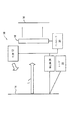
図面の詳細を参照すると、図1はこの発明を実施するコードスキャナ10を示す概略図である。スキャナ10は、バーコードのような光学コード14を距離を置いて照射する光源12を有する。バーコード14から反射された光Lは、イメージセンサ16上に画像を形成し、それはバーコード14を復号するために処理される。
Referring to the drawings in detail, FIG. 1 is a schematic diagram illustrating a
液体レンズ18は、バーコード14とイメージセンサ16との間の光路L中に挿入配置される。その液体レンズ18は、2つの透明層の間の光学的界面を有する電子光学タイプの装置であることは、当業者には分かるであろう。印加電圧の調整によって、その界面の形状が変化し、レンズの焦点距離が変わる。
The
レンズ18とイメージセンサ16との間の距離は固定されたままであるが、レンズの焦点が合うまでレンズ18の左側の距離は、印加電圧によって変化する。従って、コントローラ20がレンズ18に印加する電圧を変えるだけで、イメージセンサ16の距離範囲にバーコード14を合焦させることができる。レンズの機械的動作は不要である。しかしながら、レンズ18に印加される制御電圧は、レンズ18及びイメージセンサ16から、バーコード14までの実際の距離に関連していなければならないことが分かるであろう。
The distance between the
レンズ18の適切な制御を確実にするために、好ましくはレーザ装置とレーザ検出器24からなる測距装置(ranging apparatus)を設ける。二種類のレーザ測距技術が従来からよく知られている。パルス技術は、レーザパルスの開始とその反射による戻りの間の遅延時間を測定する。視差技術は、対象物上にスポットを形成する光線を投射し、その後、その対象物上で検出されたスポットの位置を測定する。対象物の距離は、検出されたスポットの位置から決定できる。
In order to ensure proper control of the
レーザ装置22と検出器24は、視差測距サブシステムを構成するのが好ましい。レーザ22は、光線をバーコード14に投射し、検出器24はその結果として生じた点の位置を検知して、バーコード14の距離を決定する。その後その距離を表わす信号を生成し、それがコントローラ20に印加される。それに応じて、コントローラ20はその後、それに適切に焦点を合わせるためにレンズ18に電圧を印加することができる。
検出器24の出力信号は光源12にも印加され、それによってその光強度が制御される。最も簡単なものは光源12が発光ダイオードのアレイであって、その光強度をアレイ上の点灯するダイオードの数によって(より単純には光学出力を変えることによって)制御し得る。 The output signal of the detector 24 is also applied to the light source 12, whereby the light intensity is controlled. In the simplest case, the light source 12 is an array of light emitting diodes whose light intensity can be controlled by the number of lit diodes on the array (or more simply by changing the optical output).
光源12の光強度はまた、光源投射角度を変えることによっても制御され得る。当業者であれば、それを透過率制御装置又は同様なものの角度を制御することによって機械的に実現することができ、あるいはコンデンサレンズで光学的にも実現し得ることが、分かるであろう。複数のコンデンサレンズを設けてそれらを選択するか、あるいはズームレンズ、場合によっては液体レンズさえ設けることが可能である。 The light intensity of the light source 12 can also be controlled by changing the light source projection angle. One skilled in the art will appreciate that it can be realized mechanically by controlling the angle of the transmittance controller or the like, or optically with a condenser lens. It is possible to provide a plurality of condenser lenses and select them, or even a zoom lens or even a liquid lens.
いずれにしても、コントローラを介して焦点距離と光源の照度がバーコードの距離に関連して、理想に近づく被写界深度効率を実現することが可能である。 In any case, it is possible to achieve depth-of-field efficiency that is close to ideal, with the focal length and illuminance of the light source being related to the barcode distance via the controller.
液体レンズ18は、バリオプティック(Varioptic)社製のARCTIC−414又はARCTIC−416が好ましい。しかしながら、他の液体レンズも同様に使用し得る。
The
好ましい配置において、レーザは、カメラモジュールの側部や底部ではなく頂部に搭載される。さらに、レーザは光軸から6〜15mm程度ずらす必要がある。また、LEDを照明に使用する場合、反射の影響を最小限にするために、それはモジュールのレーザとは反対側に搭載する必要がある。 In a preferred arrangement, the laser is mounted on the top rather than the side or bottom of the camera module. Furthermore, the laser needs to be shifted from the optical axis by about 6 to 15 mm. Also, if an LED is used for illumination, it must be mounted on the opposite side of the module from the laser to minimize the effect of reflection.
前述したように、この発明は、より早くコード画像の焦点を合わせることができ、可動部品の使用を避けて、関連する信頼性の問題を排除し、実質的により大きな焦点範囲があり、且つ既存の走査装置をに容易に改造できるという点において、従来技術より利点がある。 As described above, the present invention allows the code image to be focused more quickly, avoids the use of moving parts, eliminates the associated reliability issues, has a substantially larger focus range, and This is an advantage over the prior art in that it can be easily modified.
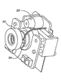
図2は、液体レンズ201とその液体レンズに近接して設置された温度センサ204とを備えた二次元撮像装置の実施例を示す。レーザ測距装置207は、図示のように液体レンズの真上に取り付けられている。温度センサ204は、液体レンズに適切な電圧を印加した後、装置が画像を取り込む前にどのくらい待つ必要があるか決定する際に温度を考慮する制御回路(図示せず)に接続される。
FIG. 2 shows an embodiment of a two-dimensional imaging device including a
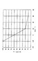
図3は、3つの異なる温度での典型的な液体レンズの応答時間を示す一組のグラフ301〜303である。特に、液体レンズが規定の画像の鮮明度のレベルに合焦するための、例えば60℃での待ち時間は、25℃での待ち時間よりかなり少ないことが示される。所定の液体レンズ又は液体レンズのタイプに対して、種々の液体レンズが異なる反応をするかもしれないが、経験的データが待ち時間の適切な値を引き出すために使用できる。レンズの応答時間は、単に適切な待ち時間のテーブルを作るためにテストされる。 FIG. 3 is a set of graphs 301-303 showing typical liquid lens response times at three different temperatures. In particular, it is shown that the waiting time, for example at 60 ° C., for the liquid lens to focus on a defined image sharpness level is considerably less than the waiting time at 25 ° C. Although various liquid lenses may respond differently to a given liquid lens or liquid lens type, empirical data can be used to derive an appropriate value for latency. The response time of the lens is simply tested to create an appropriate latency table.
図4は、温度センサ204によって測定される温度の関数として適切な待ち時間の単一のグラフを示す。最小限の待ち時間後に画像が取り込まれるように画像取込装置の制御回路をプログラムすることにより、その装置は、正確に復号するために少なくとも規定された閾値と同等な鮮明な画像を提供するのに十分な時間だけ待つが、低速及び小容量という結果になるほど長く待つことはない。
FIG. 4 shows a single graph of appropriate latency as a function of temperature measured by the
温度が異なると待ち時間が異なるので、温度の値は装置が作動する時に更新されるとよい。好ましい実施例では、コントローラは、定期的に温度の更新を要求するようにプログラムされる。あるいは、その更新は、温度センサが所定量以上の温度の変化を検出したときはいつでも行うようにしてもよい。 Since the waiting time is different for different temperatures, the temperature value should be updated when the device operates. In the preferred embodiment, the controller is programmed to periodically request temperature updates. Alternatively, the update may be performed whenever the temperature sensor detects a change in temperature of a predetermined amount or more.
この発明の好ましい実施形態を上述したが、種々の他の変更及び追加が当業者にとって明らかであろう。そのような変更又は追加は、添付の特許請求の範囲に包含されることを意図している。 While preferred embodiments of the invention have been described above, various other modifications and additions will be apparent to those skilled in the art. Such modifications or additions are intended to be encompassed by the appended claims.
Claims (10)
前記所定時間が、前記画像を取り込む画像取込装置に搭載された温度センサからの情報に少なくとも一部は基づいて予め決定される画像取込方法。 An image capturing method of applying a voltage to a liquid lens and capturing an image after waiting for a predetermined time for the liquid lens to respond to the voltage,
An image capturing method in which the predetermined time is determined in advance based at least in part on information from a temperature sensor mounted on an image capturing device that captures the image.
前記記憶装置は、前記レンズに焦点を合わせるための制御信号を印加してから画像を取り込むまでに与えるべき時間の量を示す値を設定し、前記時間の量は少なくとも一部は測定される温度に依存する撮像装置。 An imaging device having a lens, a temperature sensor, and a storage device,
The storage device sets a value indicating an amount of time to be given from the application of a control signal for focusing to the lens until the image is captured, and the amount of time is at least partly measured temperature Depends on the imaging device.
Applications Claiming Priority (1)
| Application Number | Priority Date | Filing Date | Title |
|---|---|---|---|
| PCT/US2008/072876 WO2010019136A1 (en) | 2008-08-12 | 2008-08-12 | Liquid lens with temperature compensated focus time |
Publications (2)
| Publication Number | Publication Date |
|---|---|
| JP2011530722A true JP2011530722A (en) | 2011-12-22 |
| JP2011530722A5 JP2011530722A5 (en) | 2012-02-09 |
Family
ID=41669108
Family Applications (1)
| Application Number | Title | Priority Date | Filing Date |
|---|---|---|---|
| JP2011522949A Pending JP2011530722A (en) | 2008-08-12 | 2008-08-12 | Liquid lens with temperature compensated focusing time |
Country Status (5)
| Country | Link |
|---|---|
| US (1) | US20110200314A1 (en) |
| EP (1) | EP2318863A4 (en) |
| JP (1) | JP2011530722A (en) |
| CN (1) | CN102150063A (en) |
| WO (1) | WO2010019136A1 (en) |
Cited By (3)
| Publication number | Priority date | Publication date | Assignee | Title |
|---|---|---|---|---|
| WO2020217778A1 (en) * | 2019-04-26 | 2020-10-29 | オムロン株式会社 | Image sensor |
| WO2020217777A1 (en) * | 2019-04-26 | 2020-10-29 | オムロン株式会社 | Image sensor |
| WO2021091212A1 (en) * | 2019-11-04 | 2021-05-14 | 엘지이노텍 주식회사 | Optical device |
Families Citing this family (9)
| Publication number | Priority date | Publication date | Assignee | Title |
|---|---|---|---|---|
| US10690816B2 (en) | 2013-12-31 | 2020-06-23 | Cognex Corporation | Systems and methods reduce temperature induced drift effects on a liquid lens |
| US9575221B2 (en) | 2013-12-31 | 2017-02-21 | Cognex Corporation | Systems and methods reduce temperature induced drift effects on a liquid lens |
| WO2016202392A1 (en) | 2015-06-17 | 2016-12-22 | Optotune Ag | Temperature drift compensation for liquid lenses |
| DE102017119517B4 (en) * | 2016-08-30 | 2023-10-05 | Cognex Corporation | Systems and methods for reducing temperature-related drift effects in a liquid lens |
| CN110463181B (en) * | 2017-01-24 | 2021-07-23 | Lg伊诺特有限公司 | Camera module including liquid lens module and method of controlling camera module |
| KR102521613B1 (en) * | 2018-05-04 | 2023-04-13 | 엘지이노텍 주식회사 | Control circuit of liquid lens, camera module and controlling method for liquid lens |
| DE202018107124U1 (en) | 2018-12-13 | 2020-03-18 | Sick Ag | Optoelectronic sensor |
| DE102018132015A1 (en) | 2018-12-13 | 2020-06-18 | Sick Ag | Optoelectronic sensor and method for focusing |
| KR20210116945A (en) * | 2020-03-18 | 2021-09-28 | 엘지전자 주식회사 | Mobile terminal and method for controlling the same |
Citations (2)
| Publication number | Priority date | Publication date | Assignee | Title |
|---|---|---|---|---|
| US20070063048A1 (en) * | 2005-09-14 | 2007-03-22 | Havens William H | Data reader apparatus having an adaptive lens |
| US20070177276A1 (en) * | 2006-02-01 | 2007-08-02 | Varioptic S.A. | Optical electrowetting device |
Family Cites Families (7)
| Publication number | Priority date | Publication date | Assignee | Title |
|---|---|---|---|---|
| JP4649736B2 (en) * | 2000-01-19 | 2011-03-16 | 株式会社ニコン | Liquid crystal display |
| US6806988B2 (en) * | 2000-03-03 | 2004-10-19 | Canon Kabushiki Kaisha | Optical apparatus |
| US7408717B2 (en) * | 2004-04-24 | 2008-08-05 | Koninklijke Philips Electronics N.V. | Liquid-based optical device, method for controlling such a device and electronic device |
| GB0424763D0 (en) * | 2004-11-10 | 2004-12-08 | Koninkl Philips Electronics Nv | Electronic device having a liquid-based optical device and control method therefor |
| US7748629B2 (en) * | 2006-01-31 | 2010-07-06 | Symbol Technologies, Inc. | Extended working range illumination system for an imaging-based bar code reader |
| JP4750626B2 (en) * | 2006-05-31 | 2011-08-17 | シチズンホールディングス株式会社 | Automatic focusing device |
| US20080277480A1 (en) * | 2007-05-10 | 2008-11-13 | Serge Thuries | Temperature compensated auto focus control for a microfluidic lens, such as auto focus control for a microfluidic lens of a bar code scanner |
-
2008
- 2008-08-12 WO PCT/US2008/072876 patent/WO2010019136A1/en active Application Filing
- 2008-08-12 JP JP2011522949A patent/JP2011530722A/en active Pending
- 2008-08-12 EP EP08797680A patent/EP2318863A4/en not_active Withdrawn
- 2008-08-12 US US13/055,066 patent/US20110200314A1/en not_active Abandoned
- 2008-08-12 CN CN2008801306924A patent/CN102150063A/en active Pending
Patent Citations (2)
| Publication number | Priority date | Publication date | Assignee | Title |
|---|---|---|---|---|
| US20070063048A1 (en) * | 2005-09-14 | 2007-03-22 | Havens William H | Data reader apparatus having an adaptive lens |
| US20070177276A1 (en) * | 2006-02-01 | 2007-08-02 | Varioptic S.A. | Optical electrowetting device |
Cited By (9)
| Publication number | Priority date | Publication date | Assignee | Title |
|---|---|---|---|---|
| WO2020217778A1 (en) * | 2019-04-26 | 2020-10-29 | オムロン株式会社 | Image sensor |
| WO2020217777A1 (en) * | 2019-04-26 | 2020-10-29 | オムロン株式会社 | Image sensor |
| JP2020181136A (en) * | 2019-04-26 | 2020-11-05 | オムロン株式会社 | Image sensor |
| JP2020181134A (en) * | 2019-04-26 | 2020-11-05 | オムロン株式会社 | Image sensor |
| JP7052773B2 (en) | 2019-04-26 | 2022-04-12 | オムロン株式会社 | Image sensor |
| JP7052772B2 (en) | 2019-04-26 | 2022-04-12 | オムロン株式会社 | Image sensor |
| US11689804B2 (en) | 2019-04-26 | 2023-06-27 | Omron Corporation | Image sensor |
| US11825192B2 (en) | 2019-04-26 | 2023-11-21 | Omron Corporation | Image sensor |
| WO2021091212A1 (en) * | 2019-11-04 | 2021-05-14 | 엘지이노텍 주식회사 | Optical device |
Also Published As
| Publication number | Publication date |
|---|---|
| CN102150063A (en) | 2011-08-10 |
| WO2010019136A1 (en) | 2010-02-18 |
| EP2318863A4 (en) | 2012-09-19 |
| EP2318863A1 (en) | 2011-05-11 |
| US20110200314A1 (en) | 2011-08-18 |
Similar Documents
| Publication | Publication Date | Title |
|---|---|---|
| JP2011530722A (en) | Liquid lens with temperature compensated focusing time | |
| JP2011530722A5 (en) | ||
| JP5964476B2 (en) | Photoelectric device and method for taking clear images | |
| JP2011504247A (en) | Optical code scanner with autofocus | |
| JP6153960B2 (en) | Photoelectric device and adjustment method | |
| WO1992012499A1 (en) | Bar code scanner with a large depth of field | |
| JP2018151624A5 (en) | ||
| JP6053224B2 (en) | Image reading device | |
| WO2010143662A1 (en) | Optical information reading device | |
| NO20071024L (en) | High speed automatic focusing system | |
| US10534944B1 (en) | Method and apparatus for decoding multiple symbology types | |
| JP2005283527A (en) | Apparatus for detecting foreign substance | |
| JP2012508927A5 (en) | ||
| JP2021179602A (en) | Acquisition of image data of moving object | |
| JP2012508927A (en) | High speed optical code reading | |
| US20100294839A1 (en) | Optical code scanner with automatic focusing | |
| JP2006518861A (en) | Compact automatic focusing piezoelectric actuator system | |
| JP5511632B2 (en) | Laser irradiation device | |
| WO2012115045A1 (en) | Optical information reading device | |
| JP4625734B2 (en) | Exposure pattern forming method | |
| JP5183396B2 (en) | Foreign object detection device | |
| JP2006277481A (en) | Optical information reader | |
| JP2013068761A (en) | Imaging apparatus and method for controlling imaging apparatus | |
| KR101138648B1 (en) | High speed substrate inspection apparatus and method using the same | |
| KR101302415B1 (en) | Signal process system for automatically adjusting the focus of the 3 dimensional depth lens |
Legal Events
| Date | Code | Title | Description |
|---|---|---|---|
| A521 | Written amendment |
Free format text: JAPANESE INTERMEDIATE CODE: A523 Effective date: 20111110 |
|
| A131 | Notification of reasons for refusal |
Free format text: JAPANESE INTERMEDIATE CODE: A131 Effective date: 20130625 |
|
| A02 | Decision of refusal |
Free format text: JAPANESE INTERMEDIATE CODE: A02 Effective date: 20131126 |