JP2011529586A - Diffractive liquid crystal display - Google Patents
Diffractive liquid crystal display Download PDFInfo
- Publication number
- JP2011529586A JP2011529586A JP2011521250A JP2011521250A JP2011529586A JP 2011529586 A JP2011529586 A JP 2011529586A JP 2011521250 A JP2011521250 A JP 2011521250A JP 2011521250 A JP2011521250 A JP 2011521250A JP 2011529586 A JP2011529586 A JP 2011529586A
- Authority
- JP
- Japan
- Prior art keywords
- liquid crystal
- light
- lcd
- diffraction grating
- light source
- Prior art date
- Legal status (The legal status is an assumption and is not a legal conclusion. Google has not performed a legal analysis and makes no representation as to the accuracy of the status listed.)
- Abandoned
Links
Images


Classifications
-
- G—PHYSICS
- G02—OPTICS
- G02F—OPTICAL DEVICES OR ARRANGEMENTS FOR THE CONTROL OF LIGHT BY MODIFICATION OF THE OPTICAL PROPERTIES OF THE MEDIA OF THE ELEMENTS INVOLVED THEREIN; NON-LINEAR OPTICS; FREQUENCY-CHANGING OF LIGHT; OPTICAL LOGIC ELEMENTS; OPTICAL ANALOGUE/DIGITAL CONVERTERS
- G02F1/00—Devices or arrangements for the control of the intensity, colour, phase, polarisation or direction of light arriving from an independent light source, e.g. switching, gating or modulating; Non-linear optics
- G02F1/01—Devices or arrangements for the control of the intensity, colour, phase, polarisation or direction of light arriving from an independent light source, e.g. switching, gating or modulating; Non-linear optics for the control of the intensity, phase, polarisation or colour
- G02F1/13—Devices or arrangements for the control of the intensity, colour, phase, polarisation or direction of light arriving from an independent light source, e.g. switching, gating or modulating; Non-linear optics for the control of the intensity, phase, polarisation or colour based on liquid crystals, e.g. single liquid crystal display cells
- G02F1/133—Constructional arrangements; Operation of liquid crystal cells; Circuit arrangements
- G02F1/1333—Constructional arrangements; Manufacturing methods
- G02F1/1335—Structural association of cells with optical devices, e.g. polarisers or reflectors
- G02F1/133553—Reflecting elements
- G02F1/133555—Transflectors
-
- G—PHYSICS
- G02—OPTICS
- G02F—OPTICAL DEVICES OR ARRANGEMENTS FOR THE CONTROL OF LIGHT BY MODIFICATION OF THE OPTICAL PROPERTIES OF THE MEDIA OF THE ELEMENTS INVOLVED THEREIN; NON-LINEAR OPTICS; FREQUENCY-CHANGING OF LIGHT; OPTICAL LOGIC ELEMENTS; OPTICAL ANALOGUE/DIGITAL CONVERTERS
- G02F1/00—Devices or arrangements for the control of the intensity, colour, phase, polarisation or direction of light arriving from an independent light source, e.g. switching, gating or modulating; Non-linear optics
- G02F1/01—Devices or arrangements for the control of the intensity, colour, phase, polarisation or direction of light arriving from an independent light source, e.g. switching, gating or modulating; Non-linear optics for the control of the intensity, phase, polarisation or colour
- G02F1/13—Devices or arrangements for the control of the intensity, colour, phase, polarisation or direction of light arriving from an independent light source, e.g. switching, gating or modulating; Non-linear optics for the control of the intensity, phase, polarisation or colour based on liquid crystals, e.g. single liquid crystal display cells
- G02F1/133—Constructional arrangements; Operation of liquid crystal cells; Circuit arrangements
- G02F1/1333—Constructional arrangements; Manufacturing methods
- G02F1/1335—Structural association of cells with optical devices, e.g. polarisers or reflectors
-
- G—PHYSICS
- G02—OPTICS
- G02B—OPTICAL ELEMENTS, SYSTEMS OR APPARATUS
- G02B5/00—Optical elements other than lenses
- G02B5/18—Diffraction gratings
-
- G—PHYSICS
- G02—OPTICS
- G02B—OPTICAL ELEMENTS, SYSTEMS OR APPARATUS
- G02B5/00—Optical elements other than lenses
- G02B5/18—Diffraction gratings
- G02B5/1842—Gratings for image generation
-
- G—PHYSICS
- G02—OPTICS
- G02B—OPTICAL ELEMENTS, SYSTEMS OR APPARATUS
- G02B5/00—Optical elements other than lenses
- G02B5/30—Polarising elements
-
- G—PHYSICS
- G02—OPTICS
- G02F—OPTICAL DEVICES OR ARRANGEMENTS FOR THE CONTROL OF LIGHT BY MODIFICATION OF THE OPTICAL PROPERTIES OF THE MEDIA OF THE ELEMENTS INVOLVED THEREIN; NON-LINEAR OPTICS; FREQUENCY-CHANGING OF LIGHT; OPTICAL LOGIC ELEMENTS; OPTICAL ANALOGUE/DIGITAL CONVERTERS
- G02F1/00—Devices or arrangements for the control of the intensity, colour, phase, polarisation or direction of light arriving from an independent light source, e.g. switching, gating or modulating; Non-linear optics
- G02F1/01—Devices or arrangements for the control of the intensity, colour, phase, polarisation or direction of light arriving from an independent light source, e.g. switching, gating or modulating; Non-linear optics for the control of the intensity, phase, polarisation or colour
- G02F1/13—Devices or arrangements for the control of the intensity, colour, phase, polarisation or direction of light arriving from an independent light source, e.g. switching, gating or modulating; Non-linear optics for the control of the intensity, phase, polarisation or colour based on liquid crystals, e.g. single liquid crystal display cells
- G02F1/133—Constructional arrangements; Operation of liquid crystal cells; Circuit arrangements
- G02F1/1333—Constructional arrangements; Manufacturing methods
- G02F1/1335—Structural association of cells with optical devices, e.g. polarisers or reflectors
- G02F1/1336—Illuminating devices
- G02F1/133602—Direct backlight
- G02F1/133606—Direct backlight including a specially adapted diffusing, scattering or light controlling members
- G02F1/133607—Direct backlight including a specially adapted diffusing, scattering or light controlling members the light controlling member including light directing or refracting elements, e.g. prisms or lenses
-
- G—PHYSICS
- G02—OPTICS
- G02F—OPTICAL DEVICES OR ARRANGEMENTS FOR THE CONTROL OF LIGHT BY MODIFICATION OF THE OPTICAL PROPERTIES OF THE MEDIA OF THE ELEMENTS INVOLVED THEREIN; NON-LINEAR OPTICS; FREQUENCY-CHANGING OF LIGHT; OPTICAL LOGIC ELEMENTS; OPTICAL ANALOGUE/DIGITAL CONVERTERS
- G02F1/00—Devices or arrangements for the control of the intensity, colour, phase, polarisation or direction of light arriving from an independent light source, e.g. switching, gating or modulating; Non-linear optics
- G02F1/01—Devices or arrangements for the control of the intensity, colour, phase, polarisation or direction of light arriving from an independent light source, e.g. switching, gating or modulating; Non-linear optics for the control of the intensity, phase, polarisation or colour
- G02F1/13—Devices or arrangements for the control of the intensity, colour, phase, polarisation or direction of light arriving from an independent light source, e.g. switching, gating or modulating; Non-linear optics for the control of the intensity, phase, polarisation or colour based on liquid crystals, e.g. single liquid crystal display cells
- G02F1/133—Constructional arrangements; Operation of liquid crystal cells; Circuit arrangements
- G02F1/1333—Constructional arrangements; Manufacturing methods
- G02F1/1335—Structural association of cells with optical devices, e.g. polarisers or reflectors
- G02F1/1336—Illuminating devices
- G02F1/133615—Edge-illuminating devices, i.e. illuminating from the side
-
- G—PHYSICS
- G02—OPTICS
- G02F—OPTICAL DEVICES OR ARRANGEMENTS FOR THE CONTROL OF LIGHT BY MODIFICATION OF THE OPTICAL PROPERTIES OF THE MEDIA OF THE ELEMENTS INVOLVED THEREIN; NON-LINEAR OPTICS; FREQUENCY-CHANGING OF LIGHT; OPTICAL LOGIC ELEMENTS; OPTICAL ANALOGUE/DIGITAL CONVERTERS
- G02F1/00—Devices or arrangements for the control of the intensity, colour, phase, polarisation or direction of light arriving from an independent light source, e.g. switching, gating or modulating; Non-linear optics
- G02F1/01—Devices or arrangements for the control of the intensity, colour, phase, polarisation or direction of light arriving from an independent light source, e.g. switching, gating or modulating; Non-linear optics for the control of the intensity, phase, polarisation or colour
- G02F1/13—Devices or arrangements for the control of the intensity, colour, phase, polarisation or direction of light arriving from an independent light source, e.g. switching, gating or modulating; Non-linear optics for the control of the intensity, phase, polarisation or colour based on liquid crystals, e.g. single liquid crystal display cells
- G02F1/133—Constructional arrangements; Operation of liquid crystal cells; Circuit arrangements
- G02F1/1333—Constructional arrangements; Manufacturing methods
- G02F1/1335—Structural association of cells with optical devices, e.g. polarisers or reflectors
- G02F1/1336—Illuminating devices
- G02F1/133618—Illuminating devices for ambient light
-
- G—PHYSICS
- G02—OPTICS
- G02F—OPTICAL DEVICES OR ARRANGEMENTS FOR THE CONTROL OF LIGHT BY MODIFICATION OF THE OPTICAL PROPERTIES OF THE MEDIA OF THE ELEMENTS INVOLVED THEREIN; NON-LINEAR OPTICS; FREQUENCY-CHANGING OF LIGHT; OPTICAL LOGIC ELEMENTS; OPTICAL ANALOGUE/DIGITAL CONVERTERS
- G02F2201/00—Constructional arrangements not provided for in groups G02F1/00 - G02F7/00
- G02F2201/30—Constructional arrangements not provided for in groups G02F1/00 - G02F7/00 grating
- G02F2201/305—Constructional arrangements not provided for in groups G02F1/00 - G02F7/00 grating diffraction grating
-
- G—PHYSICS
- G02—OPTICS
- G02F—OPTICAL DEVICES OR ARRANGEMENTS FOR THE CONTROL OF LIGHT BY MODIFICATION OF THE OPTICAL PROPERTIES OF THE MEDIA OF THE ELEMENTS INVOLVED THEREIN; NON-LINEAR OPTICS; FREQUENCY-CHANGING OF LIGHT; OPTICAL LOGIC ELEMENTS; OPTICAL ANALOGUE/DIGITAL CONVERTERS
- G02F2203/00—Function characteristic
- G02F2203/62—Switchable arrangements whereby the element being usually not switchable
Landscapes
- Physics & Mathematics (AREA)
- General Physics & Mathematics (AREA)
- Optics & Photonics (AREA)
- Nonlinear Science (AREA)
- Mathematical Physics (AREA)
- Chemical & Material Sciences (AREA)
- Crystallography & Structural Chemistry (AREA)
- Liquid Crystal (AREA)
- Diffracting Gratings Or Hologram Optical Elements (AREA)
- Control Of Indicators Other Than Cathode Ray Tubes (AREA)
Abstract
液晶ディスプレイ(LCD)は、光源と、前記光源から受信した光を回折するように構成された、前記光源上の光回折器と、前記光回折器の上であって、複数の液晶画素を含む液晶画素構造の間にある液晶回折格子とを備え、前記液晶回折格子は、前記回折格子への電圧差の印加に応答して変化する回折率を有し、かつ、前記変化した回折率を有する場合に、前記光回折器から受信した回折光を、前記液晶画素構造に方向づけられた、整列した光に位置合わせする。LCDは、それぞれ反射部および透過部を備えた複数の液晶画素を含んで差し支えなく、前記複数の液晶画素の少なくとも一部の反射部は、光線の少なくとも一部を外部光源から受信し、外部光源の方向に反射するように構成された再帰反射器を備える。 A liquid crystal display (LCD) includes a light source, an optical diffractor on the light source configured to diffract light received from the light source, and a plurality of liquid crystal pixels on the optical diffractor A liquid crystal diffraction grating between the liquid crystal pixel structures, the liquid crystal diffraction grating having a diffractive index that changes in response to application of a voltage difference to the diffraction grating, and having the changed diffractive index In some cases, diffracted light received from the optical diffractor is aligned with aligned light directed to the liquid crystal pixel structure. The LCD may include a plurality of liquid crystal pixels each having a reflection portion and a transmission portion, and at least some of the reflection portions of the plurality of liquid crystal pixels receive at least part of light rays from an external light source. A retroreflector configured to reflect in the direction of.
Description
本開示は、一般に、回折液晶ディスプレイ(LCD)に関する。さらに具体的には、本開示は、液晶ディスプレイ(LCD)のバックライトの光線を位置合わせする方法に関する。 The present disclosure relates generally to diffractive liquid crystal displays (LCDs). More specifically, the present disclosure relates to a method for aligning backlight rays of a liquid crystal display (LCD).
この項に記載する手法は達成されうるが、必ずしも、先に想起または達成されている手法であるわけではない。したがって、別に示唆されない限り、この項に記載される任意の手法は、単にこの項に含まれるという理由から、先行技術と見なされると考えるべきではない。 The approaches described in this section can be accomplished, but are not necessarily approaches that have been recalled or achieved previously. Thus, unless otherwise indicated, any approach described in this section should not be considered as prior art simply because it is included in this section.
さまざまな電子部品のディスプレイ用途の増大により、より良好な性能をもたらす部品の提供について、ディスプレイ製造業者への要求が強まっている。性能パラメータとしては、読みやすさ、電力消費、解像度、コスト、および直射日光下での読みやすさが挙げられる。ディスプレイ製造業者は、これらのパラメータに基づいた性能を改善するため、さまざまな技術を採用する。液晶ディスプレイの分野では、バックライトをオフにして室内照明下で読みやすい、および直射日光下で読みやすい、高い解像度のLCDを生産する技術が必要とされている。加えて、黒、白およびグレーの色合いで高い解像度を示すLCDを開発することも必要とされている。 With the increasing display applications of various electronic components, there is an increasing demand for display manufacturers to provide components that provide better performance. Performance parameters include readability, power consumption, resolution, cost, and readability in direct sunlight. Display manufacturers employ a variety of technologies to improve performance based on these parameters. In the field of liquid crystal displays, there is a need for technology to produce high resolution LCDs that are easy to read under room lighting with the backlight off and easy to read in direct sunlight. In addition, there is a need to develop LCDs that exhibit high resolution in black, white and gray shades.
従来のバックライトLCDは、1つ以上の発光ダイオードおよびライトガイドなどの光源を含む。光源から放出される光線は、すべての方向に向けられるが、液晶材料は、液晶材料が光弁として機能する場合には、単一方向に整列させた光を必要とする。したがって、直線偏光子は、光源の上に層状になり、単一面における光源の光波を偏光または整列させる働きをする。次いで、偏光は、画素、カラーフィルター、他のフィルム、および第2の偏光子を通過し、可視ディスプレイ画像を生み出す。 A conventional backlight LCD includes a light source such as one or more light emitting diodes and a light guide. Light rays emitted from the light source are directed in all directions, but liquid crystal materials require light aligned in a single direction if the liquid crystal material functions as a light valve. Thus, the linear polarizer is layered over the light source and serves to polarize or align the light waves of the light source in a single plane. The polarized light then passes through pixels, color filters, other films, and a second polarizer to produce a visible display image.
あいにく、従来の偏光子は、偏光面に向けられていない大量の光波を吸収することによって機能する。その結果、偏光子は、相当量の光強度の損失を引き起こす。光源によって生じた光の50%以上の損失も珍しいことではない。結果的に、許容できる輝度を有するディスプレイを生産するためには、光源は、第1の偏光子が受ける損失を克服するのに十分な輝度を有するように構築されなければならない。電力消費は、輝度に直接関係し、したがって、従来のLCDが消費する電力の一部は、最終的に、偏光子における光損失の形で無駄になってしまう。 Unfortunately, conventional polarizers function by absorbing large amounts of light waves that are not directed at the plane of polarization. As a result, the polarizer causes a considerable amount of light intensity loss. A loss of more than 50% of the light produced by the light source is not uncommon. Consequently, in order to produce a display with acceptable brightness, the light source must be constructed to have enough brightness to overcome the loss experienced by the first polarizer. Power consumption is directly related to brightness, so some of the power consumed by conventional LCDs is ultimately wasted in the form of light loss in the polarizer.
さらには、偏光子はLCDにかすみを生じることから、偏光子を備えたLCDは、反射率および読みやすさの低下または制限を被る。例えば、第2の偏光子は、LCD上への入射光線または周辺光線の45%相当を吸収し、LCDの反射素子から反射する際に、同一の光線の90%を吸収しうる。したがって、実際には、偏光子を使用して、紙上のテキストの外観によく似せること、または電子新聞ディスプレイに似た性能を達成することは、LCDにとって不可能である。 Furthermore, LCDs with polarizers suffer from reduced or limited reflectivity and readability, because polarizers cause blur in the LCD. For example, the second polarizer can absorb 45% of incident light or ambient light on the LCD and can absorb 90% of the same light when reflected from the reflective element of the LCD. Thus, in practice, it is impossible for LCDs to use polarizers to mimic the appearance of text on paper or to achieve performance similar to an electronic newspaper display.
ある実施の形態では、液晶ディスプレイ(LCD)は、
光源と、
前記光源から受信した光を回折するように構成された、前記光源の上にある光回折器と、
前記光回折器の上であって、複数の液晶画素を含む液晶画素構造の間にある液晶回折格子と、
を備え、
前記液晶回折格子は、前記回折格子への電圧差の印加に応答して変化する回折特性を有し、かつ、前記変化した回折特性を有する場合に、前記光回折器から受信した回折光を、前記液晶画素構造に方向づけられた、整列した光に位置合わせする。
In one embodiment, the liquid crystal display (LCD) is
A light source;
An optical diffractor overlying the light source configured to diffract light received from the light source;
A liquid crystal diffraction grating on the optical diffractor and between a liquid crystal pixel structure including a plurality of liquid crystal pixels;
With
The liquid crystal diffraction grating has a diffraction characteristic that changes in response to application of a voltage difference to the diffraction grating, and when having the changed diffraction characteristic, the diffracted light received from the optical diffractor, Align to aligned light directed to the liquid crystal pixel structure.
さまざまな実施の形態では、光回折器は、プリズムフィルムまたは第2の回折格子のいずれかを備える。ある実施の形態では、光回折器は、光を反射角の範囲内に回折するように構成され、液晶回折格子は、同一範囲内の反射角において受信した回折光を位置合わせするように構成される。 In various embodiments, the optical diffractor comprises either a prism film or a second diffraction grating. In one embodiment, the optical diffractor is configured to diffract light within a range of reflection angles, and the liquid crystal diffraction grating is configured to align received diffracted light at a reflection angle within the same range. The
ある実施の形態では、液晶回折格子0.1μm〜10μmの周期および0.1μm〜10μmの範囲の溝の深さを有する、複数の溝および壁を備える。ある実施の形態では、液晶回折格子は、0.5μmの周期および2μmの溝の深さを有する、複数の溝および壁を備える。 In one embodiment, the liquid crystal diffraction grating comprises a plurality of grooves and walls having a period of 0.1 μm to 10 μm and a groove depth in the range of 0.1 μm to 10 μm. In one embodiment, the liquid crystal diffraction grating comprises a plurality of grooves and walls having a period of 0.5 μm and a groove depth of 2 μm.
ある実施の形態では、複数の液晶画素のそれぞれは、反射部および透過部を備え、ここで、反射部は、カラーフィルターのほんの一部のみを有し、透過部の少なくとも一部は、画素の透過部をほとんどまたは完全に被覆する、1つ以上のカラーフィルターを備える。 In one embodiment, each of the plurality of liquid crystal pixels includes a reflective portion and a transmissive portion, wherein the reflective portion has only a part of the color filter, and at least a part of the transmissive portion is a part of the pixel. One or more color filters are provided that cover the transmission part almost or completely.
ある実施の形態では、液晶回折格子は、複数の液晶画素のそれぞれの透過部の上にだけ存在する。ある実施の形態では、反射部は、複数の画素の対角を占有する。ある実施の形態では、透過部は対角線上に配置される。ある実施の形態では、反射部の1%〜50%はカラーフィルターを有する。 In an embodiment, the liquid crystal diffraction grating exists only on the transmission part of each of the plurality of liquid crystal pixels. In one embodiment, the reflection unit occupies the diagonal of a plurality of pixels. In one embodiment, the transmission part is arranged on a diagonal line. In one embodiment, 1% to 50% of the reflective portion has a color filter.
ある実施の形態では、LCDは、それぞれ反射部および透過部を備えた複数の液晶画素を備え、複数の液晶画素の少なくとも一部の反射部は、光線の少なくとも一部を外部光源から受信し、外部光源の方向に反射するように構成された再帰反射器を備えている。 In an embodiment, the LCD includes a plurality of liquid crystal pixels each having a reflection portion and a transmission portion, and at least some of the reflection portions of the plurality of liquid crystal pixels receive at least a part of the light beam from an external light source, A retroreflector configured to reflect in the direction of the external light source is provided.
ある実施の形態では、複数の液晶画素すべての反射部は、再帰反射器を備える。ある実施の形態では、再帰反射器は、外部光源から受信した0次の非回折光線を、外部光源の方向に反射するように構成される。 In one embodiment, the reflecting portions of all of the plurality of liquid crystal pixels include a retroreflector. In one embodiment, the retroreflector is configured to reflect zeroth-order non-diffracted light received from an external light source in the direction of the external light source.
ある実施の形態では、再帰反射器は、反射部の上の1つ以上の無色のスペーサと一体形成される。ある実施の形態では、再帰反射器は、LCDの薄膜トランジスタ(TFT)層に形成される。 In some embodiments, the retroreflector is integrally formed with one or more colorless spacers on the reflector. In one embodiment, the retroreflector is formed in a thin film transistor (TFT) layer of the LCD.
ある実施の形態では、上述のような再帰反射器を有するLCDは、バックライト光源と、前記バックライト光源から受信した光を回折するように構成された、前記バックライト光源の上にある光回折器と、前記光回折器の上であって、複数の液晶画素を含む液晶画素構造の下にある液晶回折格子と、をさらに備え、前記液晶回折格子は、前記回折格子への電圧差の印加に応答して変化する回折率を有するように構成され、かつ、前記変化した回折率を有する場合に、前記光回折器から受信した回折光を、前記液晶画素構造に方向づけられた、整列した光に位置合わせするように構成される。 In one embodiment, an LCD having a retroreflector as described above comprises a light source overlying a backlight source and the backlight source configured to diffract light received from the backlight source. And a liquid crystal diffraction grating above the optical diffractor and below a liquid crystal pixel structure including a plurality of liquid crystal pixels, the liquid crystal diffraction grating applying a voltage difference to the diffraction grating Aligned light that is configured to have a diffractive index that changes in response to the diffracted light and that is directed to the liquid crystal pixel structure when the diffracted light received from the optical diffractor has the changed diffractive index. Configured to align with.
ある実施の形態では、上述のようなLCDは、限定はしないが、ラップトップ型コンピュータ、ノート型コンピュータ、およびネットブック・コンピュータを含めたコンピュータの一部を形成する。 In some embodiments, the LCD as described above forms part of a computer, including but not limited to laptop computers, notebook computers, and netbook computers.
本発明のさまざまな実施の形態は、本発明を例証するのであって、限定しないことを条件として、以下、添付の図面と併せて記載され、ここで、同様の記号表示は同様の要素を示す。図面は、正確な縮尺ではない。 Various embodiments of the present invention will be described below in conjunction with the accompanying drawings, wherein, without limitation, the invention is illustrated by way of illustration and not limitation, where like symbols indicate like elements . The drawings are not to scale.
液晶ディスプレイ(LCD)における光の位置合わせの方法について記載する。好ましい実施の形態および本明細書に記載の一般的な原理および特徴に対するさまざまな変更は、当業者に容易に明らかになるであろう。よって、本発明は、提示した実施の形態に限定されることは意図されておらず、本明細書に記載の原理および特徴に一致する最も広い範囲とされるべきである。 A method for aligning light in a liquid crystal display (LCD) is described. Various modifications to the preferred embodiment and the general principles and features described herein will be readily apparent to those skilled in the art. Thus, the present invention is not intended to be limited to the embodiments presented, but is to be accorded the widest scope consistent with the principles and features described herein.
ある実施の形態では、LCDは、偏光子または偏光を使用することなく、機能することができる。ある実施の形態では、LCDの反射率は、従来のディスプレイと比較して実質的に大きく、電力消費は少ない。ある実施の形態では、このようなLCDの性能は、電気泳動ディスプレイなどの電子ペーパーディスプレイの性能に近い。実施の形態は、製造工程に容易に適合することができ、映像表示を可能にするのに十分に速いディスプレイの更新レートを達成することができる。実施の形態は、LCDの上から単純反射光を受信するLCDパネル、バックライトまたは他の内部光源に由来する単純透過光を使用するパネル、または、LCD構造の上および下の両方にある光源から光を受信する半透過型パネルを含めた、LCD構造の上または下にある光を受信するLCD構造に適用可能である。 In certain embodiments, the LCD can function without the use of a polarizer or polarized light. In some embodiments, the reflectivity of the LCD is substantially greater and consumes less power than a conventional display. In certain embodiments, the performance of such LCDs is close to that of electronic paper displays such as electrophoretic displays. Embodiments can be easily adapted to the manufacturing process and can achieve display update rates that are fast enough to allow video display. Embodiments can be from LCD panels that receive simple reflected light from the top of the LCD, panels that use simple transmitted light from a backlight or other internal light source, or light sources that are both above and below the LCD structure. Applicable to LCD structures that receive light above or below the LCD structure, including transflective panels that receive light.
1.画素構造の構造概観
図1は、LCDの画素100の断面の概略図である。画素100は、液晶材料104、画素電極106、コモン電極108、反射部110、透過部112、基板114および116、スペーサ118aおよび118bを備える。
1. Structural Overview of Pixel Structure FIG. 1 is a schematic view of a cross section of a pixel 100 of an LCD. The pixel 100 includes a
ある実施の形態では、光源102または周辺光124は、画素100に光を当てる。光源102の例としては、限定はしないが、発光ダイオードバックライト(LED)、冷陰極蛍光ランプ・バックライト(CCFL)などが挙げられる。光源102はバックライト光源を備える。周辺光124は、日光、外部ランプ、または任意の他の外部光源でありうる。ある実施の形態では、光学活性材料である液晶材料104は、光源102または周辺光124からの光の偏光の軸を回転する。
In some embodiments,
液晶104は、ねじれネマチック(TN)、電界制御型複屈折方式(ECB)などでありうる。ある実施の形態では、光面の回転は、画素電極106とコモン電極108の間に印加される電位差によって決定される。ある実施の形態では、画素電極106およびコモン電極108は、インジウムスズ酸化物(ITO)でできている。さらには、各画素は画素電極106を提供するが、コモン電極108は、LCDに存在するすべての画素に共通している。
The
ある実施の形態では、反射部110は導電性であり、周辺光124を反射して、画素100に照射する。反射部110は金属でできており、画素電極106に電気的に結合することによって、反射部110とコモン電極108の間の電位差を提供する。透過部112は、光源102からの光を透過し、画素100に照射する。基板114および116は、液晶材料104、画素電極106およびコモン電極108を取り囲む。ある実施の形態では、画素電極106は基板114に位置し、コモン電極108は基板116に位置する。加えて、基板114はスイッチング素子115を含む。ある実施の形態では、スイッチング素子115は薄膜トランジスタ(TFT)でありうる。
In some embodiments, the
駆動回路130は、画素値に関する信号をスイッチング素子に送る。ある実施の形態では、駆動回路130は、低電圧差動シングナリング(LVDS)ドライバを使用する。別の実施の形態では、電圧の上昇および下降の両方を感知するトランジスタ−トランジスタ論理回路(TTL)インターフェイスが、駆動回路130に用いられる。加えて、タイミング制御装置140は、画素値に関する信号を、画素の対角透過部に必要な信号にコード化する。さらには、タイミング制御装置140は、画素に関する信号をタイミング制御装置140から取り出す場合に、LCDのセルフリフレッシュを可能にするメモリを有する。
The
ある実施の形態では、基板114と116の距離を一定に保つために、スペーサ118aおよび118bが反射部110に置かれる。
In one embodiment, spacers 118a and 118b are placed on the
画素100は、光源102または周辺光124によって照射される。画素100を通過する光の強度は、画素電極106とコモン電極108の電位差荷よって決定される。ある実施の形態では、液晶材料104は、非配向の状態にあり、画素電極106とコモン電極108の間に電位差が印加されない場合には、光は遮断される。画素電極106とコモン電極108の間に電位差が印加される場合には、液晶材料104は配向する。液晶材料104の配向性は、光を通過させる。
Pixel 100 is illuminated by
2.透過光用の回折LCD
図2は、バックライト光源からの光線を位置合わせするための第1の回折格子を有するLCDの簡易化した断面図である。明確な例を示す目的のため、ある特定の構造を簡易化した形態で示し、他の構造は省略されている。
2. Diffraction LCD for transmitted light
FIG. 2 is a simplified cross-sectional view of an LCD having a first diffraction grating for aligning light rays from a backlight source. For the purpose of illustrating a clear example, certain structures are shown in simplified form and other structures are omitted.
図2は、図1の垂直の向きとは対照的に、水平に向いている。よって、完成したLCDの基部側を表す図2の底部は、図1の左側に対応し、視聴者がディスプレイを見る側を表す図2の上部は、図1の右側に対応する。 FIG. 2 is oriented horizontally, as opposed to the vertical orientation of FIG. Thus, the bottom of FIG. 2 representing the base side of the completed LCD corresponds to the left side of FIG. 1, and the top of FIG. 2 representing the side where the viewer views the display corresponds to the right side of FIG.
図2において、光源214は、図2の向きに関して上方に均一に分散した光を放出する導光板212に連結している。従来のLCDでは、その後、光は、画素構造216A、216Bに到達する前に偏光層または偏光子を通過する。図2の実施の形態では、光回折器210が導光板212の上に配置され、光源214から受信した光を回折するように構成される。さまざまな実施の形態では、光回折器210はプリズムフィルムまたは回折格子を備える。第1の液晶回折格子202は、光回折器210の上であって、画素構造216A、216Bおよび他のLCD層220の間に積層される。下部画素構造216AはTFT層および基板を表すか、または含み、上部画素構造216Bはカラーフィルターを表すか、または含みうる。一部の実施の形態では、画素構造216A、216Bおよび液晶回折格子202は、単一構造に一体化されて差し支えなく、または、回折格子は単一の画素構造内に存在してもよい。他のLCD層220は、上部基板およびさまざまなコーティングまたはフィルムを含みうる。
In FIG. 2, the light source 214 is connected to a light guide plate 212 that emits light uniformly dispersed upward in the direction of FIG. In a conventional LCD, the light then passes through a polarizing layer or polarizer before reaching the
画素構造216A、216Bは、図1に示すように、液晶材料104、画素電極106、コモン電極108、反射部110、透過部112、基板114、およびスペーサ118aおよび118bを含みうる。他のLCD層220は、基板116および他の最高レベルのフィルム、コーティングまたは構造層を意味しうる。よって、図2の構成要素は、図1に示す種類の画素構造、または、三重モードLCD、幾つかの設計の半透過型LCD、および電子新聞として機能するように最適化されたLCDを含めた他のLCD画素構造に一体化されてもよい。
As shown in FIG. 1, the
ある実施の形態では、回折格子202は、それぞれが液晶材料で満たされた複数の溝209A、および、溝を分離し画成する複数の格子壁209Bを備える。ある実施の形態では、溝209Aと壁209Bの幅の合計は0.5μmであり、溝および壁は、約2μmの深さを有する。さまざまな実施の形態では、回折格子の周期および深さは0.1〜10μmの範囲でありうる。溝209Aにおける特定の液晶材料は重要ではなく、ディスプレイに通常用いられる種類のさまざまな従来のLC材料が使用されうる。図2に示すタイプの格子は、例えば、さまざまな入力角における周波数400〜700ナノメートルの光の全可視スペクトルにわたり、高い回折効率を示すことが判明した(ある実施の形態では90%を超える)。入力角は、典型的には60度±20度である。
In one embodiment, the
平面図で見ると、回折格子202は、細長い直線の壁209Bによって分けられた細長い直線の液晶溝209Aを含みうる。さまざまな実施の形態では、長方形のLCDパネルまたはモジュールに関して、細長い溝209Aおよび壁209Bの長さは、LCDパネルの長い側に対して平行または垂直のいずれかに方向付けられうる。
When viewed in plan view, the
実施の形態では、回折格子202は、化学エッチング、レーザエッチングおよび他の方法を用いて溝に曝露したガラスまたは酸化物でできている。回折格子202は、トランジスタ、回路、または集積電子機器を含みうる、回折格子の上部および底部側を覆い、それぞれスイッチ208を通じて電源206の柱に連結した、第1および第2の電極204A、204Bをさらに備える。よって、電源206は、電極204A、204Bに選択的に適用され、電極の間に電位差を発生する。ある実施の形態では、溝209Aは、電圧が印加されず、回折格子202を透過させる場合には、通常、第1の屈折率(回折率)を有する。
In embodiments, the
ある実施の形態では、電源206から電圧が印加されない場合に、溝209Aにおける液晶材料の屈折率(回折率)は、格子の残りの屈折率(回折率)と一致し、したがって、格子は、視聴者には、材料の均一なシートに見える。スイッチ208を閉じることにより電源206から電圧が印加される場合、液晶材料の回折率は、格子の残りの回折率とは異なるようになり;その結果として、格子に入る光は回折する。さらには、広範囲の入力角からの光が回折する。
In one embodiment, when no voltage is applied from the
透過型LCD、またはLCDの透過部に関連して、図2のLCDの動作は、次のように行う。光回折器210は、導光板212から受信した光に回折を生じるように構成される。導光板212から放出される光線230は、約60度の角度で導光板を出て、図2の傾斜した線分232で示すように、光回折器210を出る際に、約40〜140度の角度で、傾斜した光線のスペクトル分散へと回折される。ある実施の形態では、光回折器210は、赤色光を最も浅い角度で回折格子202の方向に回折し、青色光を最も急な角度で回折するように構成される。ある実施の形態では、プリズムフィルムまたは回折格子でありうる光回折器210は、赤色を最も急角度で、かつ、青色を最も浅い角度で回折する回折格子202によって生じた光の回折を厳密に相殺するような回折または屈折角を提供するように形成される。
In relation to the transmissive LCD or the transmissive part of the LCD, the operation of the LCD of FIG. 2 is performed as follows. The optical diffractometer 210 is configured to diffract the light received from the light guide plate 212. The
電極204A、204Bに電圧を印加し、回折格子202に、そこに入る光の回折を生じさせる。光学的原理は、プリズムに入り、屈折光として現れる白色光が、第2のプリズムを使用して白色光へと再結合される、というものである。したがって、図2において、光線230は、スペクトル分散して回折格子202に入り、図2の光線230の垂線部分で示されるように、白色光として整列されて現れる。
A voltage is applied to the
画素構造216A、216Bが画素の透過部分にカラーフィルターを含む場合、光は、赤、緑、および青の画素へとさらにフィルタリングされる。あるいは、光源214、導光板212、光回折器210および液晶回折格子202を組み合わせて用いて、カラーフィルターなしにモノクロ表示用に使用してもよい。
If the
よって、図2の実施の形態は、偏光子を使用せず、偏光子に関連する光損失を被ることなく、光源214からの光が画素構造216A、216Bに達する前に、効果的に整列しうる、LCD構造を提供する。壁209Bが比較的狭いことから(典型的には、幅0.25μm)、回折格子202を通過せずに壁に反射する光線によって生じる光の損失は、比較的小さい。光源214には、偏光層を使用するLCDよりも低いパワーが必要とされている。ある実施の形態では、偏光層と比較して、図2の回折格子配置を使用するLCDでは、約3分の1のパワーしか消費されないと予想される。
Thus, the embodiment of FIG. 2 does not use a polarizer and effectively aligns the light from the light source 214 before reaching the
3.反射光用の回折LCD
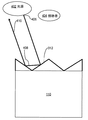
図3は、反射光の効果を補正する再帰反射器を有するLCDの単純化した図である。
3. Diffraction LCD for reflected light
FIG. 3 is a simplified diagram of an LCD having a retroreflector that corrects the effect of reflected light.
もっぱら反射モードで動作するLCDでは、画素は、照明角度を典型的には調節できない光源からの光の反射によって可視化される。このような外部光源としては、太陽光、建築物内部の天井の固定照明、ランプ、および他の光源が挙げられる。この環境では、回折されていない、光源からの光線、または0次回折光線は、視聴者に直接反射されうる。図5は、従来の平らなスムース・リフレクターを使用する画素の反射部に関連した問題を例証する、簡易化した図である。光源402は、光線502によって表す0次の一部の光線を含めた光をすべての方向に放出する。光線502は、平らな上部表面を有する反射部110にぶつかる。入射角αは反射角βと等しく、よって、光線504は視聴者404に直接反射し、ディスプレイ画像に輝点またはホットスポットとして現れる。この影響は望ましくなく、バックライトまたは透過照明なしに動作するLCDの有効性を低減する。
In LCDs operating exclusively in reflective mode, pixels are visualized by reflection of light from a light source that typically cannot adjust the illumination angle. Such external light sources include sunlight, fixed lighting on the ceiling inside the building, lamps, and other light sources. In this environment, light from the light source that is not diffracted or zero order diffracted light can be reflected directly to the viewer. FIG. 5 is a simplified diagram illustrating a problem associated with a reflective portion of a pixel using a conventional flat smooth reflector. The light source 402 emits light in all directions, including some zeroth order light rays represented by the
ある実施の形態では、溝の周期が単一の画素面積当たりの特定の最大幅から特定の最小幅まで徐々に変化する、チャープ格子を備えている、第2の回折格子が、反射部110上に用いられうる;さまざまな実施の形態では、溝の周期を段階的に増大または減少させたものが用いられうる。チャープ格子は、液晶回折格子または非LC回折格子を含みうる。あるいは、第2の回折格子は、擬似無作為または無作為に選択される周期値を有する溝を備えていてもよく、反射において白色光または白色に近い光の回折を生じる。この手法は、外部光源からのほとんどの光を回折し、ホットスポットを生じないスペクトル分散を生じさせるが、回折しない0次の光線に完全に対処するものではなく、偏光子または偏光層を使用しないディスプレイにはホットスポットを生じうる。
In one embodiment, a second diffraction grating comprising a chirped grating on the
ある実施の形態では、図3のLCDは、再帰反射器が断面にジグザグのプロファイル、または一連の三角形を示すように、線系列で接合している、傾斜した、または先のとがった反射面312を有する複数のコーナキューブを含む、再帰反射器310をさらに備える。さまざまな実施の形態では、表面312の角度は、断面に見られる三角形の底幅および底角が変化するように、変化して差し支えない。このような変化は、さらに記載するように、0次の光線を光源方向に反射すると同時に、0次ではない次数における光の回折を無作為に引き起こす。隣接した反射面312が接合する角度は重要ではなく、さまざまな実施の形態では、0.1〜90度の範囲でありうる。
In some embodiments, the LCD of FIG. 3 may include a
ある実施の形態では、再帰反射器310は、画素構造216A、216Bの画素の反射部110にのみ形成される。ある実施の形態では、再帰反射器310は、例えば、スペーサ118a、118bを使用して、画素構造216A、216Bを用いて形成される。あるいは、再帰反射器310は、LCDのTFT層に形成されて差し支えない。あるいは、反射部110は、再帰反射器構造の形態をした凹凸のある金属層を使用して形成されうる。
In one embodiment, the
動作では、再帰反射器310を使用し、非回折光を光源の方に跳ね返し、よって、視聴者には黒く見える。図4は、再帰反射器を使用する画素の反射部を例証する、簡易化した図である。この配置において、光源402からの光線406は、再帰反射器310の傾斜した反射面312の1つにぶつかる。表面312における光線406の入射角は、表面から跳ね返る光線の反射角に等しく、光線セグメント410によって示されるように、視聴者から光源402の方に方向付けられた角度で、光線を再帰反射器から出す。光線406、410は平行であり、視聴者に知覚されず、または黒色と認識されない。その結果、LCDは、明るい周辺光の条件下で、バックライトなしに、優れた反射透明度を表す。
In operation,
4.コンピュータ・ディスプレイ
実施の形態は、さまざまなLCD用途に使用されて差し支えない。ある実施の形態では、電子装置は、図1〜図5に関連して先に述べたように形成された、プロセッサおよびLCDを備える。装置の例としては、ビデオ・モニター、テレビ受信機、腕時計、置時計、および標識が挙げられる。
4). Computer Display Embodiments can be used for various LCD applications. In certain embodiments, the electronic device comprises a processor and an LCD formed as described above in connection with FIGS. Examples of devices include video monitors, television receivers, watches, table clocks, and signs.
さらに、実施の形態は、ラップトップ型コンピュータ、ノートブック、ネットブック、ハンドヘルド・コンピュータ、携帯情報端末、携帯電話、および、本明細書に記載したように形成され、コンピュータがディスプレイを生じるように駆動できる、ディスプレイの駆動回路に連結した一体化LCDを有する他のコンピュータなどのコンピューティング・デバイスを含みうる。 In addition, embodiments are formed as described in this specification for laptop computers, notebooks, netbooks, handheld computers, personal digital assistants, cellular phones, and computers that drive to produce a display. It may include a computing device such as another computer having an integrated LCD coupled to a display drive circuit.
明確な例を示す目的で、図6は、実施の形態を実行するコンピューターシステム600を例証している。さまざまな実施の形態では、コンピューターシステム600は、ラップトップ型コンピュータ、ノートブック、ネットブック、ハンドヘルド・コンピュータ、携帯情報端末、携帯電話、または一体化LCDを有する別のコンピュータのいずれかを備えうる。携帯電話などの特殊用途のコンピューティング・デバイスは、アンテナおよびセルラー無線トランシーバーなど、明確性の目的で図6では省略されている追加のハードウェア素子を含む。
For purposes of providing a clear example, FIG. 6 illustrates a
コンピューターシステム600は、情報の伝達のためのバス602または他の通信機構、および、情報を処理するためのバス602に連結したハードウェアプロセッサ604を含む。ハードウェアプロセッサ604は、例えば、汎用のマイクロプロセッサでありうる。
コンピューターシステム600はまた、プロセッサ604によって実行されるべき情報および指示を記憶するために、バス602に連結した、ランダム・アクセス・メモリ(RAM)または他の動的記憶装置などのメインメモリ606も含む。メインメモリ606はまた、プロセッサ604によって実行されるべき指示の実行の間に、一時変数または他の中間情報を記憶させるために使用して差し支えない。コンピューターシステム600は、プロセッサ604の静的情報および指示を記憶するためのバス602に連結した読み取り専用メモリ(ROM)608または他の静的記憶装置をさらに含む。磁気ディスクまたは光ディスクなどの記憶装置610が提供され、情報を記憶および指示するためのバス602に連結される。
コンピューターシステム600は、バス602を介して、液晶ディスプレイ612に接続されうる。図1、図2、図3、図4の実施の形態は、ディスプレイ612と一緒に用いて差し支えない。コンピューターシステム600は、ディスプレイの駆動回路またはチップセットを備えて差し支えなく、プロセッサ604とは別々であるか、または一体化し、プロセッサ604がディスプレイドライバに書き込んだデータに基づいた個別のLCD画素ディスプレイ信号を用いてディスプレイ612を駆動するように構成されるか、または、プロセッサ604がディスプレイのデータを書き込んだメインメモリ606の特定の部分から直接得られる。駆動回路130およびタイミング制御装置140は、例えば、プロセッサ604、および、ディスプレイ612に結合されて差し支えない。
The
英数字および他のキーを含めた入力装置614は、プロセッサ604への情報の伝達および命令選択をするためのバス602に接続される。別の種類の使用者の入力装置は、プロセッサ604への指示情報および命令選択を通信し、ディスプレイ612上のカーソル移動を制御するためのマウス、トラックボール、またはカーソル方向キーなどのカーソル移動制御616である。
コンピューターシステム600はまた、バス602に接続する通信インターフェイス618を含む。通信インターフェイス618は、ローカル・ネットワーク622に接続したネットワークリンク620に連結する、二方向データ通信を提供する。例えば、通信インターフェイス618は、総合デジタル通信網(ISDN)カード、ケーブルモデム、衛星モデム、または、対応する型の電話線へのデータ通信接続を提供するモデムでありうる。別の例として、通信インターフェイス618は、互換性のLANにデータ通信接続を提供するためのローカルエリア・ネットワーク(LAN)カードでありうる。無線リンクもまた、実行されうる。これらの任意の実行において、通信インターフェイス618は、さまざまな種類の情報を示すデジタルデータ流を運ぶ、電気、電磁、または光信号を送信および受信する。
ネットワークリンク620は、典型的には、1つ以上のネットワークを通じて他のデータ装置にデータ通信を提供する。例えば、ネットワークリンク620は、ローカル・ネットワーク622を通じて、ホストコンピューター624または、インターネット・サービス・プロバイダー(ISP)626によって動作されるデータ装置へ、接続を提供しうる。ISP626は、ひいては、通常「インターネット」628と称される、世界的なパケット・データ通信ネットワークを通じてデータ通信サービスを提供する。ローカル・ネットワーク622およびインターネット628は、両方とも、デジタルデータ流を運ぶ、電気、電磁または光信号を使用する。コンピューターシステム600にデジタルデータを往復して運ぶ、さまざまなネットワークを通じた信号および、ネットワークリンク620上および通信インターフェイス618を通じた信号は、伝送媒体の例となる形態である。
Network link 620 typically provides data communication to other data devices through one or more networks. For example, the
コンピューターシステム600は、ネットワーク、ネットワークリンク620および通信インターフェイス618を通じて、メッセージを送信し、プログラム・コードを含めたデータを受信することができる。インターネットの例では、サーバ630は、インターネット628、ISP626、ローカル・ネットワーク622および通信インターフェイス618を通じて、アプリケーション・プログラムのための要求コードを伝送する場合がある。受信コードは、それを受信し、および/または、後で使用するために記憶装置610、または他の非揮発性記憶装置に保存され、プロセッサ604によって実行されうる。
5.拡張および代替
実施の形態は、2009年7月15日出願の先行する米国特許出願番号第12/503,793号明細書に記載される種類の半透過型LCDに一体化されうる。実施の形態は、代理人整理番号60203−0020でとして2009年7月28日出願の米国特許出願番号第N号明細書に記載される種類の三重モードLCDに一体化されうる。
5). Extensions and alternatives Embodiments can be integrated into a transflective LCD of the type described in prior US patent application Ser. No. 12 / 503,793, filed Jul. 15, 2009. Embodiments can be integrated into a triple mode LCD of the type described in US Patent Application No. N, filed July 28, 2009, with agent serial number 60203-0020.
本発明の好ましい実施の形態を例証および説明してきたが、本発明は、これらの実施の形態のみに限定されないことは明らかであろう。特許請求の範囲に記載される本発明の精神および範囲から逸脱することなく、多くの変更、交換、変形、置換および等価物が、当業者には明らかになるであろう。 While the preferred embodiments of the invention have been illustrated and described, it will be clear that the invention is not limited to these embodiments only. Many alterations, substitutions, modifications, substitutions and equivalents will become apparent to those skilled in the art without departing from the spirit and scope of the invention as set forth in the claims.
Claims (29)
前記光源から受信した光を回折するように構成された、前記光源の上にある光回折器と;
前記光回折器の上であって、複数の液晶画素を含む液晶画素構造の間にある液晶回折格子と、
を備えた液晶ディスプレイ(LCD)であって、
前記液晶回折格子が、前記回折格子への電圧差の印加に応答して変化する回折特性を有するように構成され、かつ、前記変化した回折特性を有する場合に、前記光回折器から受信した回折光を、前記液晶画素構造に方向づけられた、整列した光に位置合わせするように構成される、
液晶ディスプレイ(LCD)。 A light source;
An optical diffractor overlying the light source configured to diffract light received from the light source;
A liquid crystal diffraction grating on the optical diffractor and between a liquid crystal pixel structure including a plurality of liquid crystal pixels;
A liquid crystal display (LCD) comprising:
When the liquid crystal diffraction grating is configured to have a diffraction characteristic that changes in response to application of a voltage difference to the diffraction grating, and has the changed diffraction characteristic, the diffraction received from the optical diffractor. Configured to align light with aligned light directed to the liquid crystal pixel structure;
Liquid crystal display (LCD).
前記液晶回折格子が、同一範囲内の反射角において受信した回折光を位置合わせするように構成されることを特徴とする請求項1記載のLCD。 The light diffractor is configured to diffract light into a range of reflection angles;
2. The LCD of claim 1, wherein the liquid crystal diffraction grating is configured to align received diffracted light at a reflection angle within the same range.
ここで、前記反射部がカラーフィルターのほんの一部のみを有し、
前記透過部の少なくとも一部が、前記画素の透過部をほとんどまたは完全に被覆する、1つ以上のカラーフィルターを備える
ことを特徴とする請求項1記載のLCD。 Each of the plurality of liquid crystal pixels includes a reflection portion and a transmission portion,
Here, the reflection part has only a part of the color filter,
The LCD according to claim 1, wherein at least a part of the transmissive part includes one or more color filters that almost or completely cover the transmissive part of the pixel.
前記複数の液晶画素の少なくとも一部の反射部が、光線の少なくとも一部を外部光源から受信し、前記外部光源の方向に反射するように構成された再帰反射器を含む、
液晶ディスプレイ(LCD)。 A liquid crystal display (LCD) having a plurality of liquid crystal pixels, each having a reflective portion and a transmissive portion,
At least some of the reflective portions of the plurality of liquid crystal pixels include a retroreflector configured to receive at least some of the light rays from an external light source and reflect them in the direction of the external light source;
Liquid crystal display (LCD).
前記バックライト光源から受信した光を回折するように構成された、前記バックライト光源の上の光回折器と、
前記光回折器の上にあり、複数の液晶画素を含む液晶画素構造の下にある、液晶回折格子と、
をさらに備え、
前記液晶回折格子が、前記回折格子への電圧差の印加に応答して変化する回折率を有するように構成され、かつ、前記変化した回折率を有する場合に、前記光回折器から受信した回折光を、前記液晶画素構造に方向づけられた、整列した光に位置合わせするように構成される
ことを特徴とする請求項11記載のLCD。 A backlight light source;
An optical diffractor above the backlight source configured to diffract light received from the backlight source;
A liquid crystal diffraction grating above the optical diffractor and below a liquid crystal pixel structure including a plurality of liquid crystal pixels;
Further comprising
When the liquid crystal diffraction grating is configured to have a diffractive index that changes in response to application of a voltage difference to the diffractive grating and has the changed diffractive index, the diffraction received from the optical diffractor 12. The LCD of claim 11, wherein the LCD is configured to align light with aligned light directed to the liquid crystal pixel structure.
1つ以上のプロセッサ、および
光源と、前記光源から受信した光を回折するように構成された、前記光源の上にある光回折器と、前記光回折器の上にあり、複数の液晶画素を含む液晶画素構造の下にある、液晶回折格子と、を備えた液晶ディスプレイ
を備え、
前記液晶回折格子が、前記回折格子への電圧差の印加に応答して変化する回折率を有するように構成され、かつ、前記変化した回折率を有する場合に、前記光回折器から受信した回折光を、前記液晶画素構造に方向づけられた、整列した光に位置合わせするように構成される、
コンピューティング・デバイス。 A computing device,
One or more processors; and a light source; an optical diffractor overlying the light source configured to diffract light received from the light source; A liquid crystal display with a liquid crystal diffraction grating under the liquid crystal pixel structure including,
When the liquid crystal diffraction grating is configured to have a diffractive index that changes in response to application of a voltage difference to the diffractive grating and has the changed diffractive index, the diffraction received from the optical diffractor Configured to align light with aligned light directed to the liquid crystal pixel structure;
Computing device.
前記液晶回折格子が、同一範囲内の反射角において受信した回折光を位置合わせするように構成される
ことを特徴とする請求項17記載のコンピューティング・デバイス。 The light diffractor is configured to diffract light into a range of reflection angles;
18. The computing device of claim 17, wherein the liquid crystal diffraction grating is configured to align diffracted light received at a reflection angle within the same range.
前記1つ以上のプロセッサに連結し、それぞれ反射部および透過部を備えた複数の液晶画素を含む、液晶ディスプレイ(LCD)と、
を備えたコンピューティング・デバイスであって、
前記複数の液晶画素の少なくとも一部の反射部が、光線の少なくとも一部を外部光源から受信し、外部光源の方向に反射するように構成された再帰反射器を備える、
コンピューティング・デバイス。 One or more processors;
A liquid crystal display (LCD) coupled to the one or more processors and including a plurality of liquid crystal pixels each having a reflective portion and a transmissive portion;
A computing device comprising:
At least some of the reflective portions of the plurality of liquid crystal pixels include a retroreflector configured to receive at least part of light rays from an external light source and reflect in the direction of the external light source.
Computing device.
前記バックライト光源から受信した光を回折するように構成された、前記バックライト光源の上の光回折器と、
前記光回折器の上であって、複数の液晶画素を含む液晶画素構造の下にある、液晶回折格子と、
をさらに備え、
前記液晶回折格子が、前記回折格子への電圧差の印加に応答して変化する回折率を有するように構成され、かつ、前記変化した回折率を有する場合に、前記光回折器から受信した回折光を、前記液晶画素構造に方向づけられた、整列した光に位置合わせするように構成されることを特徴とする請求項23記載のコンピューティング・デバイス。 A backlight light source;
An optical diffractor above the backlight source configured to diffract light received from the backlight source;
A liquid crystal diffraction grating above the optical diffractor and below a liquid crystal pixel structure including a plurality of liquid crystal pixels;
Further comprising
When the liquid crystal diffraction grating is configured to have a diffractive index that changes in response to application of a voltage difference to the diffractive grating and has the changed diffractive index, the diffraction received from the optical diffractor 24. The computing device of claim 23, configured to align light with aligned light directed to the liquid crystal pixel structure.
Applications Claiming Priority (3)
| Application Number | Priority Date | Filing Date | Title |
|---|---|---|---|
| US8402708P | 2008-07-28 | 2008-07-28 | |
| US61/084,027 | 2008-07-28 | ||
| PCT/US2009/051981 WO2010014624A2 (en) | 2008-07-28 | 2009-07-28 | Diffractive liquid crystal display |
Publications (2)
| Publication Number | Publication Date |
|---|---|
| JP2011529586A true JP2011529586A (en) | 2011-12-08 |
| JP2011529586A5 JP2011529586A5 (en) | 2012-09-20 |
Family
ID=41607980
Family Applications (1)
| Application Number | Title | Priority Date | Filing Date |
|---|---|---|---|
| JP2011521250A Abandoned JP2011529586A (en) | 2008-07-28 | 2009-07-28 | Diffractive liquid crystal display |
Country Status (5)
| Country | Link |
|---|---|
| US (1) | US8384861B2 (en) |
| JP (1) | JP2011529586A (en) |
| KR (1) | KR101290205B1 (en) |
| TW (1) | TWI401501B (en) |
| WO (1) | WO2010014624A2 (en) |
Families Citing this family (24)
| Publication number | Priority date | Publication date | Assignee | Title |
|---|---|---|---|---|
| US8913000B2 (en) * | 2007-06-15 | 2014-12-16 | Ricoh Co., Ltd. | Video playback on electronic paper displays |
| US8416197B2 (en) * | 2007-06-15 | 2013-04-09 | Ricoh Co., Ltd | Pen tracking and low latency display updates on electronic paper displays |
| KR101363022B1 (en) * | 2008-12-23 | 2014-02-14 | 삼성디스플레이 주식회사 | Organic light emitting diode display |
| CN101957523B (en) * | 2010-05-26 | 2013-01-09 | 天马微电子股份有限公司 | Liquid crystal grating module and planar/three-dimensional switchable liquid crystal display device |
| WO2012018887A2 (en) * | 2010-08-03 | 2012-02-09 | Cornell University | Angle sensitive pixel (asp)-based image processing system, method, and applications |
| US20130314631A1 (en) * | 2011-02-10 | 2013-11-28 | The Hong Kong University Of Science And Technology | Pixel structure of liquid crystal display utilizing asymmetrical diffraction |
| US9535280B2 (en) * | 2011-05-27 | 2017-01-03 | Corning Incorporated | Engineered antiglare surface to reduce display sparkle |
| US9946134B2 (en) * | 2012-08-24 | 2018-04-17 | Lumentum Operations Llc | Variable optical retarder |
| KR102358478B1 (en) * | 2015-03-31 | 2022-02-04 | 엘지디스플레이 주식회사 | Tft array structure |
| US10254454B2 (en) | 2015-06-15 | 2019-04-09 | Magic Leap, Inc. | Display system with optical elements for in-coupling multiplexed light streams |
| US10798371B2 (en) | 2015-09-05 | 2020-10-06 | Leia Inc. | Multiview display with head tracking |
| ES2952094T3 (en) | 2015-09-05 | 2023-10-27 | Leia Inc | Multi-view display with head tracking |
| CA3007486C (en) | 2016-01-30 | 2020-07-28 | Leia Inc. | Multibeam element-based backlight and display using same |
| KR102367308B1 (en) | 2016-01-30 | 2022-02-24 | 레이아 인코포레이티드 | Multi-beam element-based backlighting with convergence points |
| CN105589256A (en) * | 2016-03-11 | 2016-05-18 | 京东方科技集团股份有限公司 | Display device |
| JP6887447B2 (en) | 2016-05-23 | 2021-06-16 | レイア、インコーポレイテッドLeia Inc. | Diffractive multi-beam element backlight |
| WO2018022028A1 (en) * | 2016-07-26 | 2018-02-01 | Leia Inc. | Bar collimator, backlight system and method |
| EP3523574A4 (en) | 2016-10-05 | 2020-06-10 | LEIA Inc. | Mode-selectable backlight, method, and display employing directional scattering features |
| EP3523575A4 (en) | 2016-10-05 | 2020-06-17 | LEIA Inc. | Transparent display and method |
| WO2018112101A1 (en) | 2016-12-14 | 2018-06-21 | Magic Leap, Inc. | Patterning of liquid crystals using soft-imprint replication of surface alignment patterns |
| CN106547142B (en) * | 2017-01-20 | 2020-05-05 | 京东方科技集团股份有限公司 | Electronic display device and display device |
| KR102315682B1 (en) | 2017-05-11 | 2021-10-21 | 레이아 인코포레이티드 | Microstructured multi-beam element backlighting |
| KR102309395B1 (en) | 2017-10-02 | 2021-10-06 | 레이아 인코포레이티드 | Multiview camera array, multiview system, and method with camera sub-arrays with shared cameras |
| CN107741666B (en) * | 2017-10-27 | 2020-08-04 | 上海天马微电子有限公司 | Display device |
Family Cites Families (40)
| Publication number | Priority date | Publication date | Assignee | Title |
|---|---|---|---|---|
| US4850681A (en) * | 1986-04-07 | 1989-07-25 | Canon Kabushiki Kaisha | Optical modulation device |
| JP3163887B2 (en) * | 1993-04-23 | 2001-05-08 | 松下電器産業株式会社 | Projection display device |
| EP0757806B1 (en) | 1995-02-28 | 2004-04-28 | Philips Electronics N.V. | Electro-optical device |
| JP3406242B2 (en) | 1998-10-15 | 2003-05-12 | シャープ株式会社 | Liquid crystal display |
| EP1281022A1 (en) | 2000-05-04 | 2003-02-05 | Koninklijke Philips Electronics N.V. | Illumination unit for a device having a multi-color reflective liquid crystal display |
| US6690438B2 (en) | 2001-04-06 | 2004-02-10 | Citizen Watch Co., Ltd. | Liquid crystal display panel |
| DE60206964T2 (en) | 2001-12-06 | 2006-07-27 | Koninklijke Philips Electronics N.V. | TRANSLECTIVE LIQUID CRYSTAL DISPLAY DEVICE |
| JP4013584B2 (en) | 2002-02-22 | 2007-11-28 | セイコーエプソン株式会社 | Color filter substrate, color filter substrate manufacturing method, liquid crystal display device, and electronic apparatus |
| JP2004045757A (en) | 2002-07-11 | 2004-02-12 | Seiko Epson Corp | Manufacturing method for color filter, electrooptical device and electronic appliance |
| TW588195B (en) | 2002-07-30 | 2004-05-21 | Hong-Da Liu | Reflector structure in a liquid crystal display having light condensing effect |
| JP4483214B2 (en) | 2002-08-07 | 2010-06-16 | セイコーエプソン株式会社 | Electro-optical device, electronic equipment |
| US7008409B2 (en) | 2002-09-24 | 2006-03-07 | Spiezio Cindy L | Disposable nursing breast pad with medication |
| JP2004279765A (en) | 2003-03-17 | 2004-10-07 | Toray Ind Inc | Color filter for liquid crystal display device and liquid crystal display device |
| TWI240906B (en) | 2003-04-09 | 2005-10-01 | Ind Tech Res Inst | Driving method of transflective liquid-crystal display device |
| JP4232523B2 (en) * | 2003-04-24 | 2009-03-04 | 旭硝子株式会社 | Optical modulator and optical attenuator |
| JP4269788B2 (en) | 2003-06-10 | 2009-05-27 | 旭硝子株式会社 | Reflective light modulator and variable optical attenuator |
| KR100584085B1 (en) * | 2003-07-02 | 2006-05-29 | 학교법인 한양학원 | Dynamically controllable light modulator using phase diffraction grating and its application to display device |
| WO2005052674A1 (en) * | 2003-11-27 | 2005-06-09 | Asahi Glass Company, Limited | Optical element using liquid crystal having optical isotropy |
| WO2005101106A1 (en) * | 2004-04-15 | 2005-10-27 | Koninklijke Philips Electronics N.V. | Transflective lcd display device |
| JP4328738B2 (en) | 2004-05-06 | 2009-09-09 | キヤノン株式会社 | LCD color display |
| JP4111180B2 (en) | 2004-09-02 | 2008-07-02 | セイコーエプソン株式会社 | Liquid crystal display device and electronic device |
| US7209212B2 (en) * | 2004-09-15 | 2007-04-24 | China Institute Of Technology | Tunable optical integrated element using liquid crystal as active layer |
| US7388635B2 (en) | 2004-11-26 | 2008-06-17 | Kyocera Corporation | Liquid crystal display device and display equipment using the same |
| TW200638101A (en) | 2005-02-02 | 2006-11-01 | Asahi Glass Co Ltd | The devices of light flux changing and projected display apparatus |
| US7502085B2 (en) | 2005-04-26 | 2009-03-10 | Samsung Electronics Co., Ltd. | Display device having functional transparent plate in prismatic structure on retarder provided on polarizer above display panel assembly |
| DE102005031448A1 (en) * | 2005-07-04 | 2007-01-11 | Polyic Gmbh & Co. Kg | Activatable optical layer |
| KR20070024198A (en) | 2005-08-26 | 2007-03-02 | 삼성전자주식회사 | Back light unit of direct light type and liquid crystal display |
| JP2007065647A (en) | 2005-08-30 | 2007-03-15 | Samsung Electronics Co Ltd | Liquid crystal display device, and module for driving the same and method of driving the same |
| WO2007042852A1 (en) | 2005-10-13 | 2007-04-19 | Nokia Corporation | Illumination method for displaying different graphical layouts |
| TW200728805A (en) | 2006-01-17 | 2007-08-01 | Wintek Corp | Transflective LCD, transflective pixel structure and driving method of the same |
| US20070242197A1 (en) | 2006-04-12 | 2007-10-18 | 3M Innovative Properties Company | Transflective LC Display Having Backlight With Spatial Color Separation |
| JP2008015125A (en) | 2006-07-05 | 2008-01-24 | Nikon Corp | Display element, display device and camera |
| JP2008052259A (en) | 2006-07-26 | 2008-03-06 | Toshiba Matsushita Display Technology Co Ltd | Liquid crystal display device |
| US20080030656A1 (en) | 2006-08-01 | 2008-02-07 | 3M Innovative Properties Company | Transflective lc display with internal reflector and reflective polarizer |
| US7746431B2 (en) | 2006-11-21 | 2010-06-29 | One Laptop Per Child Association, Inc | Dual mode display |
| TWI354159B (en) * | 2006-11-21 | 2011-12-11 | One Laptop Per Child Ass Inc | Dual mode display |
| KR101270165B1 (en) | 2006-12-29 | 2013-05-31 | 삼성디스플레이 주식회사 | Reflection and transmission type of display panel and display apparatus employing the same |
| JP2009123553A (en) | 2007-11-15 | 2009-06-04 | Sumitomo Chemical Co Ltd | Light guide plate, planar light source, and liquid crystal display device |
| WO2009084604A1 (en) * | 2007-12-27 | 2009-07-09 | Asahi Glass Co., Ltd. | Liquid crystal element, optical head device, and variable optical modulation element |
| US8830426B2 (en) | 2010-11-17 | 2014-09-09 | Pixel Qi Corporation | Color shift reduction in transflective liquid crystal displays |
-
2009
- 2009-07-28 TW TW098125404A patent/TWI401501B/en not_active IP Right Cessation
- 2009-07-28 US US12/510,424 patent/US8384861B2/en not_active Expired - Fee Related
- 2009-07-28 KR KR1020117004635A patent/KR101290205B1/en active IP Right Grant
- 2009-07-28 JP JP2011521250A patent/JP2011529586A/en not_active Abandoned
- 2009-07-28 WO PCT/US2009/051981 patent/WO2010014624A2/en active Application Filing
Also Published As
| Publication number | Publication date |
|---|---|
| TW201013260A (en) | 2010-04-01 |
| WO2010014624A2 (en) | 2010-02-04 |
| US20100026930A1 (en) | 2010-02-04 |
| US8384861B2 (en) | 2013-02-26 |
| KR20110034035A (en) | 2011-04-04 |
| KR101290205B1 (en) | 2013-07-30 |
| WO2010014624A3 (en) | 2010-04-15 |
| TWI401501B (en) | 2013-07-11 |
Similar Documents
| Publication | Publication Date | Title |
|---|---|---|
| JP2011529586A (en) | Diffractive liquid crystal display | |
| KR100518408B1 (en) | Dual liquid crystal display using of dual front light | |
| JP2006139283A (en) | Liquid crystal display device and fabrication method thereof | |
| JP2008077119A (en) | Liquid crystal display using dual light unit | |
| JP2007065695A (en) | Dual liquid crystal display device using dual front light unit | |
| EP2416210B1 (en) | Display device | |
| JP2008090173A (en) | Display device | |
| US8253888B2 (en) | Liquid crystal display device | |
| US9759957B2 (en) | Transflective liquid crystal display panel and a liquid crystal display device | |
| US20180284539A1 (en) | Transflective lcd | |
| US20090310071A1 (en) | Transreflective display panel and display apparatus including the same | |
| US20110134367A1 (en) | Polarization sheet and liquid crystal display device having the same | |
| JP4506183B2 (en) | Liquid crystal device and projection display device | |
| KR100975750B1 (en) | Dual liquid crystal display using of dual front light | |
| JP2007004162A (en) | Display panel assembly and display apparatus having the same | |
| KR20120077608A (en) | Liquid crystal display device | |
| US7535526B1 (en) | Transmission-reflection type liquid crystal display device having a light transmitting region in a reflecting film | |
| KR100989248B1 (en) | Dual liquid crystal display using of dual front light | |
| KR20060110928A (en) | Transflective type liquid crystal display device | |
| JP4152963B2 (en) | Transflective liquid crystal display device and manufacturing method thereof | |
| JP4607237B2 (en) | Liquid crystal display device and manufacturing method thereof | |
| KR101085135B1 (en) | Liquid Crystal Display Device | |
| KR20050104693A (en) | A reflective-transmisstion liquid crystal display device and the fabricating method thereof | |
| JP2005128340A (en) | Reflector and liquid crystal display applying reflector | |
| JP2007052261A (en) | Liquid crystal display device |
Legal Events
| Date | Code | Title | Description |
|---|---|---|---|
| A521 | Written amendment |
Free format text: JAPANESE INTERMEDIATE CODE: A523 Effective date: 20120727 |
|
| A621 | Written request for application examination |
Free format text: JAPANESE INTERMEDIATE CODE: A621 Effective date: 20120727 |
|
| A762 | Written abandonment of application |
Free format text: JAPANESE INTERMEDIATE CODE: A762 Effective date: 20130913 |