JP2011523810A - System for combining inputs from electronic musical instruments and electronic music devices - Google Patents
System for combining inputs from electronic musical instruments and electronic music devices Download PDFInfo
- Publication number
- JP2011523810A JP2011523810A JP2011509714A JP2011509714A JP2011523810A JP 2011523810 A JP2011523810 A JP 2011523810A JP 2011509714 A JP2011509714 A JP 2011509714A JP 2011509714 A JP2011509714 A JP 2011509714A JP 2011523810 A JP2011523810 A JP 2011523810A
- Authority
- JP
- Japan
- Prior art keywords
- input
- input signal
- channel
- audio
- output
- Prior art date
- Legal status (The legal status is an assumption and is not a legal conclusion. Google has not performed a legal analysis and makes no representation as to the accuracy of the status listed.)
- Pending
Links
Images


Classifications
-
- G—PHYSICS
- G10—MUSICAL INSTRUMENTS; ACOUSTICS
- G10H—ELECTROPHONIC MUSICAL INSTRUMENTS; INSTRUMENTS IN WHICH THE TONES ARE GENERATED BY ELECTROMECHANICAL MEANS OR ELECTRONIC GENERATORS, OR IN WHICH THE TONES ARE SYNTHESISED FROM A DATA STORE
- G10H1/00—Details of electrophonic musical instruments
- G10H1/18—Selecting circuits
-
- G—PHYSICS
- G10—MUSICAL INSTRUMENTS; ACOUSTICS
- G10H—ELECTROPHONIC MUSICAL INSTRUMENTS; INSTRUMENTS IN WHICH THE TONES ARE GENERATED BY ELECTROMECHANICAL MEANS OR ELECTRONIC GENERATORS, OR IN WHICH THE TONES ARE SYNTHESISED FROM A DATA STORE
- G10H1/00—Details of electrophonic musical instruments
- G10H1/0033—Recording/reproducing or transmission of music for electrophonic musical instruments
- G10H1/0041—Recording/reproducing or transmission of music for electrophonic musical instruments in coded form
- G10H1/0058—Transmission between separate instruments or between individual components of a musical system
-
- G—PHYSICS
- G10—MUSICAL INSTRUMENTS; ACOUSTICS
- G10H—ELECTROPHONIC MUSICAL INSTRUMENTS; INSTRUMENTS IN WHICH THE TONES ARE GENERATED BY ELECTROMECHANICAL MEANS OR ELECTRONIC GENERATORS, OR IN WHICH THE TONES ARE SYNTHESISED FROM A DATA STORE
- G10H1/00—Details of electrophonic musical instruments
- G10H1/46—Volume control
-
- H—ELECTRICITY
- H04—ELECTRIC COMMUNICATION TECHNIQUE
- H04H—BROADCAST COMMUNICATION
- H04H60/00—Arrangements for broadcast applications with a direct linking to broadcast information or broadcast space-time; Broadcast-related systems
- H04H60/02—Arrangements for generating broadcast information; Arrangements for generating broadcast-related information with a direct linking to broadcast information or to broadcast space-time; Arrangements for simultaneous generation of broadcast information and broadcast-related information
- H04H60/04—Studio equipment; Interconnection of studios
- H04H60/05—Mobile studios
-
- G—PHYSICS
- G10—MUSICAL INSTRUMENTS; ACOUSTICS
- G10H—ELECTROPHONIC MUSICAL INSTRUMENTS; INSTRUMENTS IN WHICH THE TONES ARE GENERATED BY ELECTROMECHANICAL MEANS OR ELECTRONIC GENERATORS, OR IN WHICH THE TONES ARE SYNTHESISED FROM A DATA STORE
- G10H2210/00—Aspects or methods of musical processing having intrinsic musical character, i.e. involving musical theory or musical parameters or relying on musical knowledge, as applied in electrophonic musical tools or instruments
- G10H2210/155—Musical effects
- G10H2210/265—Acoustic effect simulation, i.e. volume, spatial, resonance or reverberation effects added to a musical sound, usually by appropriate filtering or delays
- G10H2210/281—Reverberation or echo
-
- G—PHYSICS
- G10—MUSICAL INSTRUMENTS; ACOUSTICS
- G10H—ELECTROPHONIC MUSICAL INSTRUMENTS; INSTRUMENTS IN WHICH THE TONES ARE GENERATED BY ELECTROMECHANICAL MEANS OR ELECTRONIC GENERATORS, OR IN WHICH THE TONES ARE SYNTHESISED FROM A DATA STORE
- G10H2210/00—Aspects or methods of musical processing having intrinsic musical character, i.e. involving musical theory or musical parameters or relying on musical knowledge, as applied in electrophonic musical tools or instruments
- G10H2210/155—Musical effects
- G10H2210/265—Acoustic effect simulation, i.e. volume, spatial, resonance or reverberation effects added to a musical sound, usually by appropriate filtering or delays
- G10H2210/295—Spatial effects, musical uses of multiple audio channels, e.g. stereo
-
- G—PHYSICS
- G10—MUSICAL INSTRUMENTS; ACOUSTICS
- G10H—ELECTROPHONIC MUSICAL INSTRUMENTS; INSTRUMENTS IN WHICH THE TONES ARE GENERATED BY ELECTROMECHANICAL MEANS OR ELECTRONIC GENERATORS, OR IN WHICH THE TONES ARE SYNTHESISED FROM A DATA STORE
- G10H2240/00—Data organisation or data communication aspects, specifically adapted for electrophonic musical tools or instruments
- G10H2240/171—Transmission of musical instrument data, control or status information; Transmission, remote access or control of music data for electrophonic musical instruments
- G10H2240/175—Transmission of musical instrument data, control or status information; Transmission, remote access or control of music data for electrophonic musical instruments for jam sessions or musical collaboration through a network, e.g. for composition, ensemble playing or repeating; Compensation of network or internet delays therefor
-
- G—PHYSICS
- G10—MUSICAL INSTRUMENTS; ACOUSTICS
- G10H—ELECTROPHONIC MUSICAL INSTRUMENTS; INSTRUMENTS IN WHICH THE TONES ARE GENERATED BY ELECTROMECHANICAL MEANS OR ELECTRONIC GENERATORS, OR IN WHICH THE TONES ARE SYNTHESISED FROM A DATA STORE
- G10H2240/00—Data organisation or data communication aspects, specifically adapted for electrophonic musical tools or instruments
- G10H2240/171—Transmission of musical instrument data, control or status information; Transmission, remote access or control of music data for electrophonic musical instruments
- G10H2240/201—Physical layer or hardware aspects of transmission to or from an electrophonic musical instrument, e.g. voltage levels, bit streams, code words or symbols over a physical link connecting network nodes or instruments
- G10H2240/211—Wireless transmission, e.g. of music parameters or control data by radio, infrared or ultrasound
Landscapes
- Engineering & Computer Science (AREA)
- Physics & Mathematics (AREA)
- Acoustics & Sound (AREA)
- Multimedia (AREA)
- Signal Processing (AREA)
- Circuit For Audible Band Transducer (AREA)
- Amplifiers (AREA)
- Stereophonic System (AREA)
Abstract
複数の電子音楽デバイスによって生成される入力信号を組合せるための装置は、複数のオーディオバスと複数のセグメントとを備える。各セグメントは、少なくとも1つの電気音楽デバイスから少なくとも1つの入力信号を受信し、その少なくとも1つの入力信号を複数のオーディオバスのうちの1つに届けるように構成された入力回路と、オーディオバスの中の対応する1つのオーディオバスと各々関連付けられており、複数のセグメントの中の別のセグメントによって受信され、複数のオーディオバスの中の他のオーディオバスで配送される入力信号から独立してオーディオバスの中の対応する1つのオーディオバスで配送される入力信号の少なくとも1つの特性を変えるように各々構成された複数の可変調整デバイスと、複数のオーディオバスの各々で配送される入力信号を組合せて出力信号にするように構成されたミキサーとを備える。 An apparatus for combining input signals generated by a plurality of electronic music devices comprises a plurality of audio buses and a plurality of segments. Each segment receives at least one input signal from at least one electrical music device and has an input circuit configured to deliver the at least one input signal to one of the plurality of audio buses; Each associated with a corresponding one audio bus in the audio, received by another segment in the plurality of segments, and independent of the input signal delivered on the other audio bus in the plurality of audio buses Combining a plurality of variable adjustment devices each configured to change at least one characteristic of an input signal delivered on a corresponding one audio bus in the bus and an input signal delivered on each of the plurality of audio buses And a mixer configured to produce an output signal.
Description
(関連出願の相互参照)
本出願は、2008年5月15日に出願された米国仮出願第61/053,391号の便益を主張するものであり、その出願の内容全体が参照により本明細書に援用される。
(Cross-reference of related applications)
This application claims the benefit of US Provisional Application No. 61 / 053,391, filed May 15, 2008, the entire contents of which are incorporated herein by reference.
本発明は、楽器(電子楽器やエレクトロアコースティック楽器など)および同様のデバイスからの入力を組合せるシステムに関する。 The present invention relates to musical instruments (such as electronic musical instruments and electroacoustic musical instruments) and systems that combine inputs from similar devices.
エレキギター、ピックアップ付きアコースティックギター、エレキベース、マイクロフォンなどの電子楽器やエレクトロアコースティック楽器は、それらの音を増幅および/または修正するのに、アンプなどの電子機器に依存している。バンドリハーサルなど、複数の演奏者をセッティングする場合、各演奏者がアンプを持っている場合があり、バンド全体中には、バンド全体の出力を制御および監視するためのミキサーが複数ある場合がある。例えば、RollsMX41ミキサーやMackie1202などの製品は、複数の入力チャネルを受け取ることができ、各入力を操作可能であり、1つのオーディオミックスを生成する。 Electronic musical instruments such as electric guitars, acoustic guitars with pickups, electric basses, and microphones, and electroacoustic instruments rely on electronic devices such as amplifiers to amplify and / or correct their sound. When setting multiple performers, such as band rehearsals, each performer may have an amplifier, and there may be multiple mixers in the entire band to control and monitor the output of the entire band. . For example, products such as the Rolls MX41 mixer and Mackie 1202 can accept multiple input channels, can manipulate each input, and produce one audio mix.
多くの場合、バンドリハーサルは「消音で(silently)」行われるのが望ましい。すなわち、ヘッドフォンにバンドの音を供給することによって楽器が最小限の音響を出すようにするのが望ましい。ヘッドフォンアンプは消音リハーサルを可能にするものであり、つまり複数の入力を受信し、それらの入力を組合せて1つの出力信号にし、その出力信号を各演奏者が装着するヘッドフォンに供給する。しかし、ヘッドフォンアンプは、各演奏者が自らのヘッドフォンに供給される特定の入力ミックスを構成する構成部分を個別に制御できない。むしろ、別の機器(「ミキサー」)によって共通のミックスが生成され、そのミックスが各演奏者のヘッドフォンまたは他のリスニングデバイスに送られる。そのため演奏者は、例えばSamson社やPreSonus社製のヘッドフォンアンプをいくつか使用して、自身のヘッドフォン内で自身の入力チャネルの音量を上げる(「私を強調」コンセプト)くらいのことしかできない。しかし、ヘッドフォンアンプを使用しても、依然としてヘッドフォンアンプの前段で共通のミックスが作り出され、ミックス全体の変更がすべての聴き手に影響するようになる。そのため、ヘッドフォンアンプとミキサーとを一緒に使用しても、他の入力チャネルに対する個々の修正はできない。 In many cases, it is desirable that the band rehearsal be performed “silently”. In other words, it is desirable to provide the instrument with minimal sound by supplying band sound to the headphones. The headphone amplifier enables mute rehearsal, that is, receives a plurality of inputs, combines these inputs into one output signal, and supplies the output signal to headphones worn by each performer. However, the headphone amplifier cannot individually control the components that make up a particular input mix that each player supplies to his headphones. Rather, a separate mix ("mixer") generates a common mix that is sent to each performer's headphones or other listening device. Therefore, the performer can only do some of the volume of his input channel within his headphones (the “emphasize me” concept) using several headphone amplifiers, for example from Samson or PreSonus. However, using a headphone amplifier still creates a common mix in front of the headphone amplifier, and changes to the entire mix will affect all listeners. Therefore, even if a headphone amplifier and a mixer are used together, individual corrections to other input channels are not possible.
本発明の一般的な一態様では、装置が複数のオーディオバスと複数のセグメントとを備える。各セグメントは、少なくとも1つの電気音楽デバイスから少なくとも1つの入力信号を受信し、その少なくとも1つの入力信号を複数のオーディオバスのうちの1つに届けるように構成された入力回路と、複数のオーディオバスの中の対応する1つのオーディオバスと各々関連付けられており、複数のセグメントの中の別のセグメントによって受信され、複数のオーディオバスの中の他のオーディオバスで配送される入力信号から独立してオーディオバスの中の対応する1つのオーディオバスで配送される入力信号の少なくとも1つの特性を変えるように各々構成された複数の可変調整デバイスと、複数のオーディオバスの各々で配送される入力信号を組合せて出力信号にするように構成されたミキサーとを備える。 In one general aspect of the invention, a device comprises a plurality of audio buses and a plurality of segments. Each segment receives at least one input signal from at least one electrical music device, and inputs circuitry configured to deliver the at least one input signal to one of the plurality of audio buses, and a plurality of audio Each is associated with a corresponding audio bus in the bus and is independent of the input signal received by another segment in the plurality of segments and delivered on the other audio bus in the plurality of audio buses. A plurality of variable adjustment devices each configured to change at least one characteristic of an input signal delivered by a corresponding one of the audio buses, and an input signal delivered by each of the plurality of audio buses And a mixer configured to combine them into an output signal.
実施形態は以下のうちの1つ以上を備え得る。入力信号の少なくとも1つの特性は、その入力信号のゲインを備える。入力回路は、複数のオーディオバスの1つにその少なくとも1つの入力信号を届ける前に、その少なくとも1つの入力信号の少なくとも1つの特性(例えばゲイン)を調整する回路を備える。入力回路は、第1のオーディオバスの第1のチャネルと第2のチャネルの各々に届けられる少なくとも1つの第1の入力信号の比率を調整する回路を備える。この装置は、その出力信号のボリュームを調整し、その出力信号をヘッドフォンやデジタルレコーダなどの出力デバイスに届けるように構成された出力回路を備える。この装置は、ファントム電源スイッチを備える。複数のオーディオバスおよび複数のセグメントはハウジング内に格納されており、例えば、複数のチャネルがそのハウジング内で放射状に配置されている。ハウジングは持ち運び可能であり、セグメントの少なくとも1つは遠隔操作が可能である。この装置は、ドッキングステーションを備える。 Embodiments can include one or more of the following. At least one characteristic of the input signal comprises the gain of the input signal. The input circuit comprises a circuit that adjusts at least one characteristic (eg, gain) of the at least one input signal before delivering the at least one input signal to one of the plurality of audio buses. The input circuit includes a circuit that adjusts a ratio of at least one first input signal delivered to each of the first channel and the second channel of the first audio bus. The apparatus includes an output circuit configured to adjust the volume of the output signal and deliver the output signal to an output device such as a headphone or a digital recorder. This device comprises a phantom power switch. The plurality of audio buses and the plurality of segments are stored in a housing. For example, a plurality of channels are arranged radially in the housing. The housing is portable and at least one of the segments is remotely operable. This apparatus comprises a docking station.
別の態様において、本発明は、複数の電子音楽デバイスによって生成される入力信号を組合せるための方法に関する。この方法は、対応する複数のセグメントに複数の入力信号を受信することと、オーディオバスに各入力信号を送ることと、セグメントごとに、互いの入力信号および他の各チャネルから独立して各入力信号の少なくとも1つの特性を調整し、その複数の入力信号を組合せて出力信号にすることとを備える。
実施形態は、以下のうちの1つ以上を備え得る。入力信号の少なくとも1つの特性は、その入力信号のゲインを備える。方法は、オーディオバスに各入力信号を送る前に各入力信号のゲインを調整することを備える。オーディオバスに各入力信号を送ることは、オーディオバスの第1のチャネルと第2のチャネルとの各々に送信される入力信号の比率を調整することを備える。方法は、出力信号のボリュームを調整することと、出力信号をヘッドフォンなどの出力デバイスに届けることとを備える。
In another aspect, the invention relates to a method for combining input signals generated by a plurality of electronic music devices. This method receives a plurality of input signals to a corresponding plurality of segments, sends each input signal to an audio bus, and each input for each segment independently from each other's input signal and each other channel. Adjusting at least one characteristic of the signal and combining the plurality of input signals into an output signal.
Embodiments may include one or more of the following. At least one characteristic of the input signal comprises the gain of the input signal. The method comprises adjusting the gain of each input signal before sending each input signal to the audio bus. Sending each input signal to the audio bus comprises adjusting a ratio of input signals transmitted to each of the first channel and the second channel of the audio bus. The method comprises adjusting the volume of the output signal and delivering the output signal to an output device such as a headphone.
複数のオーディオバスと複数のセグメントとを備える装置は、大音量でのリハーサルによる騒音によって近隣住民に迷惑がかかることなどを理由に、最小限の音響だけを出して「消音で」合同リハーサルを行う必要がある演奏者のグループにとって役立つ。この装置により、各演奏者は、他の各演奏者が聞くチャネルの組み合わせから独立して、自分が聞くチャネルの組み合わせを制御することができる。各演奏者は自身の音楽ニーズまたは嗜好に最適な組み合わせを生成できるため、この性能により、もっと有意義なリハーサルが可能となる。この装置の操作は単純明快であることから、音響技師や音響技術者を必要とせず、楽曲のリハーサルまたは演奏の間に演奏者自身で行うことができる。さらにこの装置は、デジタル音楽レコーダまたはコンピュータなどのデバイスに接続可能であるため、リハーサルを録音することができ、録音したチャネルの組み合わせを調整することもできる。現在利用可能なデバイスは、各演奏者に対し、自身が聞いている内容を独立して調整する性能を提供しない。上記装置は軽量で持ち運びも可能であることから、リハーサル・スタジオ、家、学校、寮の部屋、演奏会場など、さまざまな場所で簡単に使用することができる。 A device that has multiple audio buses and multiple segments performs joint rehearsal with “silence” with only minimal sound, for example, because the noise caused by rehearsal at high volume may disturb local residents. Useful for a group of performers who need it. This device allows each performer to control the channel combinations that he or she hears independently of the channel combinations that each other player listens to. This performance allows for a more meaningful rehearsal because each performer can generate the best combination for his or her musical needs or preferences. Since the operation of this apparatus is simple and clear, it does not require a sound engineer or sound engineer, and can be performed by the player himself during the rehearsal or performance of the music. Furthermore, since this apparatus can be connected to a device such as a digital music recorder or a computer, rehearsals can be recorded, and combinations of recorded channels can be adjusted. Currently available devices do not provide each performer with the ability to independently adjust what they are listening to. Since the above device is lightweight and portable, it can be easily used in various places such as rehearsal studios, homes, schools, dormitory rooms, and performance halls.
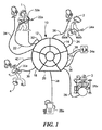
図1を参照すると、グループリハーサルシステム10が示されている。リハーサルシステム10により、演奏者1、2、3、4は合同で消音リハーサルを行うことができ、各演奏者は「ミックス」、つまり自分が聞く楽器の組み合わせを個々に制御することができる。このようにして、各演奏者は、他の演奏者が聞くミックスに影響を及ぼすことなく、自身のニーズまたは嗜好に合った独自のミックスを生成することができる。リハーサルシステム10は、電子音楽信号またはチャネルを受信するための複数のチャネル12、14、16、18、20から構成される。図1に示す実施例において、各チャネルは、そのチャネルと関連付けられた各種電子音楽デバイスから入力22、24、26、28または30を受け取る。ここでは、例えば、入力22、24、26、28、30は、エレキギター22a、ベースギター24a、電子ドラムキット26a、電子音楽プレーヤ28aおよびマイクロフォン30aとそれぞれ関連付けられている。キーボードなど、他の電子音楽デバイスを使用することができる。あるチャネルは、複数のデバイスから入力を受信してもよい。例えばチャネル12は、エレキギター22aおよびマイクロフォン32aから入力22および32を受信する。以下に詳述するとおり、各チャネルは、チャネル12、14、16、18、20のすべてによって受信される入力ミックスを生成する。各チャネル内では、そのチャネルへの入力のボリュームと他の各チャネルへの入力のボリュームとを独立して調整し、各チャネルで独自の入力ミックスを生成することができる。ミックスのボリューム全体が制御されてもよい。いくつかの実施形態では、残響およびパンエフェクトなど、各入力の他の特性が調整されてもよい。各チャネルにおける入力ミックスは、そのチャネルと関連付けられた出力デバイスに届けられる出力信号34、36、38または40を構成する。例えば、出力デバイスは、ヘッドフォン、コンピュータ、デジタルレコーダ、イヤーモニタまたはスピーカでもよい。いくつかの実施形態では、リハーサルシステム10のチャネルは5つより多くても少なくてもよい。
Referring to FIG. 1, a
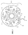
図2および図2Aでは、リハーサルシステム10内でチャネル12、14、16、18、20が放射状に配置されている。リハーサルシステム10は、電源92に接続されている。各チャネルは、入力部50、チャネル制御部74、帯域制御部80、および出力部86を含む。リハーサルシステム10は、グローバルコントロール部102も含む。
2 and 2A,
図2aを参照すると、1つのチャネルのレイアウトの分解図が示されている。入力部50は、1つ以上のモノラル入力チャネル52と1つ以上のステレオ入力チャネル54とを含んでもよく、もしくはモノラル入力チャネルを1つだけ、またはステレオ入力チャネル1つだけを含んでもよい。モノラル入力チャネル52は、第1のモノラル入力56と第2のモノラル入力58とを含む。第1のモノラル入力56は、マイクロフォン用のXLR入力であり、ゲインを設定するためにプリアンプとトリムコントロール62とを必要とする。モノラル入力56および58と関連付けられたLED60は、入力信号が最小しきい値を上回ることが検出されると緑色に点灯し、入力信号のゲインレベルがプリアンプクリッピングに接近した場合(入力信号がクリッピングを10dB下回る場合など)には黄色に点灯し、入力信号のゲインレベルがプリアンプクリッピングに達すると赤色に点灯する。LED60は、入力信号のゲインレベルに関する情報を伝達するために、LCDスクリーンと交換してもよい。第2のモノラル入力58は、TRケーブルとTRSケーブルとを受承するように設計された1/4インチTRSジャックである。第2のモノラル入力58は、アコースティックギター、エレキギター・アンプモデラー、キーボード、ベースギター、ベースギター・アンプモデラー、圧電式ピックアップまたは電子ドラムなどの電子楽器からの入力を受け取る。第2のモノラル入力58は、トリムコントロールと、第1のモノラル入力56に関連付けられたLED60と類似したLEDライト(図示せず)とを有してもよい。また、第2のモノラル入力58は、アコースティックギターまたはベースギターからの直接入力(すなわちプリアンプを伴わない入力)のインピーダンス整合を改善するために、高インピーダンススイッチ(図示せず)を有してもよい。ステレオ入力チャネル54は2つのステレオ入力66と68とを有する。これらは、平衡または不平衡入力を受け取るTRSジャックである。別の実施形態では、単一のステレオTRSジャックが使用される。ステレオ入力66は必要に応じてモノラル入力として作用するように配線される。ステレオ入力チャネル54は、ゲインコントロール70と、LED60と同じように動作するLED72とを有する。チャネルの定格(RMS)入力電圧を可変できるようにステレオ入力チャネル54に+4dbu〜10dbVのスイッチ64を組み込むことができる。また、同様の+4dbu〜10dbVのスイッチをモノラル入力チャネル52に組み込んでもよい。
Referring to FIG. 2a, an exploded view of the layout of one channel is shown. The
チャネル制御部74は、パンエフェクトを作り出すために出力信号の右チャネルと左チャネルとの間での入力信号の配分を制御するロケーションコントロール76を含む。チャネル制御部74は、そのチャネルの入力信号のレベルを調整するためのエフェクトレベルコントロール78も含む。例えば、エフェクトレベルコントロール78は、そのチャネルに適用される残響効果の度合を調整し得る。このチャネルコントロールは、そのチャネルの入力信号に影響を及ぼす他のコントロールを有してもよい。そして、イコライゼーションコントロール77、効果の種類選択およびレベル制御(図示せず)、75Hzの「高パス」EQスイッチ(図示せず)、および他のコントロールを有してもよい。
The
帯域制御部80は、そのモノラル入力チャネルのレベルとリハーサルシステム10の各チャネル12、14、16、18、20のステレオ入力チャネルとを調整するための5つのコントロールを含む。例えば、図2Aの分解断面部がチャネル12のレイアウトを示している場合、コントロール82は、チャネル14のモノラル入力とステレオ入力とのレベルを調整し、コントロール84は、チャネル16のモノラル入力とステレオ入力とのレベルを調整する。一般に、帯域制御部80におけるコントロールの数は、リハーサルシステム10のチャネル数に対応する。本明細書に示すとおり、ステレオチャネルとモノラルチャネルとを1つのチャネルに組合せる場合には、コントロール80が、1つのコントロール、2つのコントロール(1つはステレオ入力用で1つはモノラル入力用)、または2つの同心コントロールを有するデバイスを介してモノラル入力とステレオ入力との両方のレベルを調整してもよい。
出力部86は、ミックスを出力デバイスに接続するための1/4インチ出力ジャック88と、出力のゲインを調整するためのゲインレベルノブ90とを含む。他の実施形態では、出力ジャックが、1/8インチTRS、RCA、USB、ミニDIN構造または他のタイプのコネクタであってもよい。
The
グローバルコントロール部102は、すべてのチャネルに等しく作用するコントロールを含む。ファントム電源スイッチ104は、48V直流電力をすべてのモノラル入力に供給して、ファントム電力を必要とするコンデンサマイクロフォン、直接入力ボックス、およびデバイスを作動させる。エフェクトコントロール106は、そのチャネルによって使用される残響などのエフェクトのタイプを決定する。
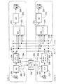
図3を参照すると、チャネル12と14とについて、リハーサルシステム10の主な機能構成要素が示されている。他のチャネル16、18、20は、同様の機能構成要素を有する。チャネル12では、オーディオ電気入力信号200が入力部202に入り、チャネル14では、オーディオ電気入力信号210が入力部206に入る。これらの入力信号は、楽器、マイクロフォンまたはデジタル音楽プレーヤを含むさまざまなデバイスによって提供されてよく、各入力部は、複数のデバイスから入力信号を同時に受け取ってもよい。入力部202と206とを使用して、ユーザは、入力信号200、210のレベルを、特定の入力デバイスに最適なレベルに設定することができる。
Referring to FIG. 3, the main functional components of the
入力信号200、210の各々は、チャネル12と14とにおけるチャネル制御部204、208にそれぞれ渡される。チャネル制御部204、208は、パンコントロール、残響、イコライゼーション、および他の効果を適用することにより、修正された信号205、209をそれぞれ生成する。ユーザが修正を希望しない場合には、修正された信号205、209が入力信号200、210と同一であってもよい。修正された信号205、209は、オーディオバス212、214にそれぞれ届けられる。同様に、オーディオバス216、218、220は、修正された信号をチャネル16、18、20から受信する。
Each of the input signals 200 and 210 is passed to channel
各オーディオバス212、214、216、218、220によって配送される修正された信号は、チャネル12と14の帯域制御部222、224にそれぞれ入る。帯域制御部222は、ミックス223に含まれる各オーディオバス212、214、216、218、220からの信号のレベルを制御することにより、チャネル12の個々のミックス223を作り出す。例えば、帯域制御部は、オーディオバス212からの信号のレベルを100%に、オーディオバス214からの信号のレベルを75%に、オーディオバス216、218、220からの信号のレベルを50%に設定してよい。同様に、帯域制御部224は、チャネル14の個々のミックス225を作り出す。オーディオバス212、214、216、218、220からの信号のレベルは、ミックス223とミックス225とで異なってもよい。同様に、チャネル16、18、20も、オーディオバス212、214、216、218、220で個々の信号ミックスを作り出す帯域制御部を有する。
The modified signals delivered by each
帯域制御部222と224とで生成されるミックス223と225とを表す信号は、出力部226と228とにそれぞれ送られる。各出力部は、出力信号のレベルを調整するためのコントロールを含む。例えば、ヘッドフォン230でチャネル12を聴いているユーザは、ミックス223を聞くことができ、出力部226のコントロールを使用して、ミックス223の全体的なレベルを変えることができる。同様に、ヘッドフォン232でチャネル14を聴いているユーザは、ミックス225を聞き、制御することができる。各出力部は、ヘッドフォン、コンピュータ、デジタルレコーダ、イヤーモニタ、スピーカなどの出力デバイスと接続するための1/4インチTRSジャック、1/8インチTRSジャック、USBポートなど、さまざまなタイプの外部接続部も含む。
Signals representing the
リハーサルシステム10のいくつかの実施形態では、グローバルコントロール部102が2つ以上のチャネルに組み込まれている。本実施例では、グローバルコントロール部102がチャネル12、14にのみ接続されており、他の実施形態では、グローバルコントロール部102がチャネル12、14、16、18、20の一部または全部に接続されてもよい。グローバルコントロール部102は、残響などのエフェクトを入力信号200、210に提供し、48Vファントム電源238などの非オーディオ機能を提供する。各チャネル12、14からの入力信号200、210は、グローバルコントロール部102に送信され、そこで所与のエフェクトがその信号に適用される。次に各信号は、その起点チャネルに対応するチャネル制御部204、206に送られ(236)、そこでその信号のレベルを上記のとおりに調整することができる。一般に、エフェクトプロセッサは、グローバルコントロール部102を通じて、またはチャネル制御部204、206を通じてのように個々のチャネルを通じて、すべてのチャネルを等しく制御し得る。
In some embodiments of the
図4を参照すると、チャネル12、14、20について、リハーサルシステム10の回路の概略図が示されている。チャネル12、14(そしてチャネル16、18、ただしこれらの詳細は明瞭化のため図示せず)は、モノラル入力チャネルを有し、それに対応した回路構造を有する。チャネル20はステレオ入力チャネルを有する。チャネル12では、入力部202が、1/4インチTRSジャック403によって接続されたXLR入力402を含む。入力信号200は、ゲインコントロール406によって制御されるプリアンプ404に渡される。本実施形態では、チャネル制御部204のパンコントロール410が、オーディオバス212のそれぞれ右側と左側とに送信される信号205a、205bの量を設定する。他のオーディオバス214、216、218、220は、チャネル14、16、18、20からの信号をそれぞれ配送する。オーディオバスによって配送される信号は、チャネル12の帯域制御部222に入る。帯域制御部222では、ポテンショメータやエンコーダなどのコントロール422が、ミックス223に含まれるオーディオバス212からの信号の量を調整する。同様に、コントロール424、426、428、430は、チャネル12のミックス223に含まれるオーディオバス214、216、218、220からの信号の量をそれぞれ調整する。調整された信号は、単一の出力バス432でミックス223に組合わされる。出力バス432は、ミックス223を出力部226に送信し、そこで、コントロール436によって制御されるアンプ434が、ヘッドフォンジャックなどの出力コネクタ438に送信されるミックスのレベルを調整する。チャネル14、16、18は、チャネル12の回路構造と同等の回路構造を有する。特に各チャネルは、各チャネルのミックスが他の各チャネルのミックスから独立することができる独自の出力バスを有する。チャネル20は、入力信号を受け取るための2つのTRS入力472と474とを含むステレオチャネルを有する。回路要素476により、デバイスが入力474に接続されていない場合に入力472がモノラル入力として機能することができる。入力ゲインコントロール478が、アンプ473と475とを制御して、左側の477チャネルと右側の479チャネルとの両方で入力信号を同時に増幅する。次にその信号は、パンコントロール480によって調整され、オーディオバス220に到着する。チャネル20の以降の回路構造は、チャネル12に関する上記回路構造に等しい。
Referring to FIG. 4, a schematic diagram of the circuit of the
リハーサルシステム10の他の特徴は、以下のとおりである。入力部50は、独自のチャネル制御部74と専用のオーディオバスとを有する内蔵ドラムマシン(またはMIDIシーケンサ)を含んでもよい。次に各チャネル12、14、16、18、20は、そのドラムマシンのオーディオバスを通る信号を制御するためのコントロールを帯域制御部80に有してもよい。同様に、帯域制御部が、演奏またはリハーサルの録音を可能にするために、その出力部86で内蔵マルチチャネル・オーディオ・レコーディング・デバイスに接続されていてもよい。エレキギターおよびベースギター用アンプのモデル作成機能または電子ドラムあるいはキーボード用のMIDIサウンドモジュールがチャネル制御部74に組み込まれてもよい。ギターチューナが1つ以上のチャネル制御部74またはグローバルコントロール部102に備えられていてもよい。有線または無線リモコンを使用して、例えば、リハーサルシステム10から離れて座っているドラマーが自身のチャネルのコントロールにリモートアクセスできるようにすることもできる。例えばソロの音量を変更できるように、所与のチャネルの信号の出力を一時的に増やすゲインブーストコントロールおよびフットスイッチをチャネル制御部74に備えることもできる。AC電源を必要とするデバイスがリハーサルシステム10を電源として使用できるように、リハーサルシステム10は音声回路とは別の配電システムを備えることができる。
Other features of the
図5を参照すると、リハーサルシステム500の代替実施形態は、512、514、516、518、520、522、524、526という8つのチャネルを有する。グローバルエフェクトプロセッサが、すべてのチャネルからの信号に適用されるエフェクトを制御するエフェクトコントロール538と、すべてのチャネルまたはXLRジャックを備えたチャネルだけにファントム電力を供給する電力コントロール540とを有する。ファントム電力が供給されると、LED542が点灯する。チャネル512、516、518、524はモノラル入力部を有し、チャネル514、520、522、526はステレオ入力部とモノラル入力部とを有する。各チャネルは、入力部、チャネル制御部、帯域制御部、および出力部を有する。帯域制御部は、各チャネルから受信される信号のレベルを調整するための8つのコントロール530を有しており、独自のミックスを各チャネルで生成することができる。各チャネルは、パンコントロール532およびレベルコントロール534などのエフェクトコントロールを含んでおり、グローバルエフェクトプロセッサからいったん返されたチャネルの信号のレベルを調整する。
Referring to FIG. 5, an alternative embodiment of the
図6を参照すると、代表チャネル512と代表チャネル514について、リハーサルシステム500の回路の概略図が示されている。他のチャネル516、518、524は、チャネル512の回路構造と同等の回路構造を有する。他のチャネル520、522、526は、チャネル514の回路構造と同等の回路構造を有する。リハーサルシステム500の回路を構成する多数の要素が、図4に示されるリハーサルシステム10の要素に対応する。チャネル512において、入力部620は、48V直列ファントム電源回路622と、ファントム電源のオンとオフとを切り換えるためのスイッチ624と、LED610とを備える。チャネル制御部626は、入力信号をエフェクトプロセッサ604に送信するエフェクトレベルコントロール602を含む。この信号はチャネル制御部626を出て、オーディオバス612に送信される。リハーサルシステム500は、8つのオーディオバス612、614、616、618、620、622、624、626を含み、各々がチャネル512、514、516、518、520、522、524、526からそれぞれ信号を受信する。チャネル512の帯域制御部636は、出力バス630におけるミックス638に備わっている各オーディオバスからの信号のレベルを判断する。出力バス630は、ミックス638を出力部640に送信する。独自の信号ミックスが他の各チャネルから独立してチャネルごとに生成できるように、各チャネルは別々の出力バスを有する。チャネル514は、入力信号をエフェクトプロセッサ608に送信するコントロール606も含む。チャネル514は、任意である第2の出力634によって描写される。この場合におけるこの出力は、コンピュータへの直接録音を可能にするUSBオーディオアナログ・デジタル変換デバイスである。
Referring to FIG. 6, a schematic diagram of a circuit of the
本明細書に記載されているリハーサルシステムでは、リハーサルシステムの本体の複数のセグメントとして複数のチャネルが具体化されている。例えば、図2を再度参照すると、チャネル12、14、16、18、20の各々は、リハーサルシステム10の本体96の一セグメントを構成する。
In the rehearsal system described herein, multiple channels are embodied as multiple segments of the body of the rehearsal system. For example, referring again to FIG. 2, each of the
図7を参照すると、リハーサルシステム700の一実施形態では、1つ以上のチャネル712、714、716、718、720がリモコンを使用して遠隔操作可能である。複数のリモコンが使用される場合、各リモコンは1つのチャネルと関連付けられている。示されている実施例では、チャネル712、718がリモコン722、728によってそれぞれ制御され、チャネル714、716、720は遠隔操作が可能ではない。他の実施形態では、チャネルの他の組み合わせがリモコンによって制御される。チャネル712は、リハーサルシステム700の本体704と物理的に別であるリモコン722によって制御され、有線接続706を介して本体704に接続されている。チャネル718は、本体704から取り外し可能であり、かつチャネル718が位置する本体704の空間710に収納されるリモコン728によって制御される。リモコン728は、有線接続708を介して本体704にも接続されている。別の実施形態では、リモコン722、728が本体704に無線接続されている。リモコン722、728は、それぞれチャネル712、718の入力部、チャネル制御部、帯域制御部、および出力部のいずれかまたは全部の機能を管理する。例えば、図7に示す実施形態において、リモコン722は、帯域制御ノブ780と、出力ノブ786と、チャネル712の遠隔操作を可能にするエフェクトリターンノブ788とを備える。帯域制御ノブ780は、リハーサルシステム700の各チャネル714、716、718、720の入力チャネルのレベルを調整するためのコントロールを含む。出力ノブ786は、ヘッドフォンなどの出力デバイスに送信される出力信号のボリュームを制御する。エフェクトリターンノブ788は、チャネル712に送信される入力信号のレベルを調整する。いくつかの実施形態では、リモコン722、728のうちの少なくとも1つが、グローバルコントロール部702の機能も管理する。いくつかの実施例では、電子音楽デバイスがリハーサルシステム700に直接接続される。他の実施例では、ドラムセットやマイクロフォンなどの電子音楽デバイスは、リハーサルシステム700にではなく、(リモコン722または728などの)リモコンに接続される。
Referring to FIG. 7, in one embodiment of the
図8Aを参照すると、一実施形態において、リハーサルシステム800の本体804は、ドッキングステーション802にドッキングされる。このドッキングステーションは、リハーサルシステム800の基本性能に機能を追加する1つ以上のデバイスを備える。ドッキングステーション802は、リハーサルシステム800の各チャネル812、814、816、818、820がその出力ミックスをドッキングステーションに直接送信できるようにするコネクタ(図示せず)を備える「直接出力」ドックである。図8Bを参照すると、ドッキングステーション802に備わっているハードディスクレコーダ804が、リハーサルシステム800を通じてオーディオレコーディングを録音または再生することを可能にする。ドッキングステーション802におけるアンプ808のアレイ806が、リハーサルシステム800を使用してライブ演奏用のスピーカを駆動させることを可能にする。充電バッテリ式ドッキングステーション810により、リハーサルシステム800はACコンセントから電力供給を受けなくても機能することができる。ドッキングステーション800に備わっている無線送信器822および受信器824は、リハーサルシステム800のチャネル812、814、816、818、820と関連付けられた送信器および受信器を制御し、楽器、ヘッドフォン、マイクロフォンまたは他の電子音楽デバイスの無線利用を可能にする。パーソナル音楽プレーヤ型ドッキングステーション826およびコネクタ828により、リハーサルシステム800はiPod(登録商標)やMP3プレーヤなどのパーソナル音楽プレーヤとの仲介を行うことができ、録音、バッキングトラックの再生、およびパーソナル音楽プレーヤのオペレーティングシステムとの他の通信が可能になる。
Referring to FIG. 8A, in one embodiment, the
図2Aを再度参照すると、リハーサルシステム10の更なる特徴は、録音用途で使用されるチャネルなど、チャネルの出力を演奏者が監査することを可能にするレコーディング出力リスニングスイッチ94である。レコーディング出力リスニングスイッチ94を使用して、演奏者は、自身のチャネルでミックスを聴くことから、録音用途で使用されるチャネルでミックスを聴くことへと速やかに切り換えることができる。例えば、図2Aがチャネル12を示している場合、レコーディング出力リスニングスイッチ94により、チャネル12を使用している演奏者は、例えばチャネル16の出力を聴くことができる。レコーディング出力リスニングスイッチ94は、リハーサルシステム10のチャネル12、14、16、18または20のうちの少なくとも1つに、またはその付近に位置している。
Referring again to FIG. 2A, a further feature of the
図9を参照すると、一実施形態において、リハーサルシステム900は、「仮想部屋」をシミュレートする部屋シミュレーションモジュール902を備える。すなわちこの部屋シミュレーションモジュールは、特定位置での音楽演奏と関連付けられた音響効果を生成する。一実施例では、部屋シミュレーションモジュールにより、演奏者は仮想部屋を小さい部屋から大きな部屋に変更することができる。別の実施例では、部屋シミュレーションモジュールにより、ロンドンのアビー・ロード・スタジオやシカゴのバディ・ガイズ・レジェンズ・クラブのステージといった著名な演奏空間のオーディオ・レスポンス・コピーを演奏者が選択することができる。部屋シミュレーションモジュール902は、デジタル信号プロセッサ904と、ノブやタッチスクリーンLCDなどの制御機構906とを介して特定の部屋の演奏空間の音響効果を生成する。デジタル信号プロセッサには、部屋または演奏空間全体での音の響き方など、さまざまなタイプの部屋と演奏空間とに関する音響パラメータが予めプログラムされている。特定位置での音楽演奏と関連付けられた出力音を生成するために、部屋シミュレーションモジュール902は、予めプログラムされた音響パラメータを基に、リハーサルシステム900の信号に音響効果を適用する。一実施形態では、リハーサルシステム900のユーザがコンピュータ908を用いて仮想部屋を作り出し、コネクタ910を介してその仮想部屋を部屋シミュレーションモジュール902に送信する。部屋シミュレーションモジュール902は、仮想部屋の音響パラメータを判断し、その仮想部屋での音楽演奏と関連付けられた音響効果を生成する。本実施形態では、現実の世界では不可能な音響効果を生成することが可能である。
Referring to FIG. 9, in one embodiment, the
オーディオフィードバックとデータロギングとを使用した別の実施形態では、リハーサルシステムがリハーサルシステムを使用してユーザフィードバックを演奏者に提供することにより、例えば演奏者が自分たちの演奏を改善するのに役立てたりする。アルゴリズムが、演奏者の連携度やドラマーの1分当たりのビート数の一定度を追跡し、記録し、演奏者に報告する。一実施例では、選択した整合性しきい値を満たす演奏に対して、「良好」を意味するトーンや観衆からの拍手の音という形でオーディオフィードバックが提供される。 In another embodiment using audio feedback and data logging, the rehearsal system can use the rehearsal system to provide user feedback to performers, for example, to help performers improve their performance. To do. The algorithm tracks, records, and reports to the performer the player's degree of cooperation and the drummer's constant number of beats per minute. In one embodiment, audio feedback is provided for performances that meet a selected consistency threshold in the form of a tone that means “good” or a sound of applause from the audience.
なお、前述の説明は例示を意図するものであって、本発明の範囲を制限することを意図するものではなく、本発明の範囲は添付の特許請求の範囲によって定義されることを理解すべきである。他の実施形態は以下の特許請求の範囲内のものである。 It should be understood that the foregoing description is intended to be illustrative and not intended to limit the scope of the present invention, which is defined by the appended claims. It is. Other embodiments are within the scope of the following claims.
Claims (21)
複数のセグメントであって、各セグメントが、
少なくとも1つの電気音楽デバイスから少なくとも1つの入力信号を受信し、当該少なくとも1つの入力信号を前記複数のオーディオバスの1つに届けるように構成された入力回路と、
前記複数のオーディオバス中の対応する1つのオーディオバスと各々関連付けられており、前記複数のセグメントの中の別のセグメントによって受信され、前記複数のオーディオバスの中の他のオーディオバスで配送される入力信号から独立して前記オーディオバス中の前記対応する1つのオーディオバスで配送される入力信号の少なくとも1つの特性を変えるように各々構成された複数の可変調整デバイスと、
前記複数のオーディオバスの各々で配送される前記入力信号を組合せて出力信号にするように構成されたミキサーとを含む、前記複数のセグメントと
を備える装置。 Multiple audio buses,
Multiple segments, each segment
An input circuit configured to receive at least one input signal from at least one electrical music device and deliver the at least one input signal to one of the plurality of audio buses;
Each associated with a corresponding one of the plurality of audio buses, received by another segment of the plurality of segments, and delivered on another audio bus of the plurality of audio buses A plurality of variable adjustment devices each configured to change at least one characteristic of an input signal delivered on the corresponding one audio bus in the audio bus independently of an input signal;
A plurality of segments including a mixer configured to combine the input signals delivered on each of the plurality of audio buses into an output signal.
複数の入力信号をそれらの対応付けられた複数のセグメントで受信し、
各入力信号をオーディオバスに送り、
各セグメントにおいて、
各入力信号の少なくとも1つの特性を、他の各入力信号から独立してかつ他の各セグメントから独立して、調整し、
前記複数の入力信号を出力信号に組合せること
を備える方法。 A method for combining input signals generated by a plurality of electronic music devices, comprising:
Receiving multiple input signals in their associated segments,
Send each input signal to the audio bus,
In each segment
Adjusting at least one characteristic of each input signal independently of each other input signal and independently of each other segment;
Combining the plurality of input signals into an output signal.
Applications Claiming Priority (3)
| Application Number | Priority Date | Filing Date | Title |
|---|---|---|---|
| US5339108P | 2008-05-15 | 2008-05-15 | |
| US61/053,391 | 2008-05-15 | ||
| PCT/US2009/044018 WO2009140538A2 (en) | 2008-05-15 | 2009-05-14 | Systems for combining inputs from electronic musical instruments and devices |
Related Child Applications (1)
| Application Number | Title | Priority Date | Filing Date |
|---|---|---|---|
| JP2015142816A Division JP6219344B2 (en) | 2008-05-15 | 2015-07-17 | Apparatus and method for combining inputs from electronic musical instruments and electronic music devices |
Publications (2)
| Publication Number | Publication Date |
|---|---|
| JP2011523810A true JP2011523810A (en) | 2011-08-18 |
| JP2011523810A5 JP2011523810A5 (en) | 2012-06-28 |
Family
ID=41314897
Family Applications (2)
| Application Number | Title | Priority Date | Filing Date |
|---|---|---|---|
| JP2011509714A Pending JP2011523810A (en) | 2008-05-15 | 2009-05-14 | System for combining inputs from electronic musical instruments and electronic music devices |
| JP2015142816A Active JP6219344B2 (en) | 2008-05-15 | 2015-07-17 | Apparatus and method for combining inputs from electronic musical instruments and electronic music devices |
Family Applications After (1)
| Application Number | Title | Priority Date | Filing Date |
|---|---|---|---|
| JP2015142816A Active JP6219344B2 (en) | 2008-05-15 | 2015-07-17 | Apparatus and method for combining inputs from electronic musical instruments and electronic music devices |
Country Status (7)
| Country | Link |
|---|---|
| US (4) | US8119900B2 (en) |
| EP (1) | EP2297860B1 (en) |
| JP (2) | JP2011523810A (en) |
| CN (1) | CN102047566B (en) |
| AU (1) | AU2009246252B2 (en) |
| TW (1) | TWI447706B (en) |
| WO (1) | WO2009140538A2 (en) |
Cited By (3)
| Publication number | Priority date | Publication date | Assignee | Title |
|---|---|---|---|---|
| JP2016006976A (en) * | 2008-05-15 | 2016-01-14 | ジャムハブ コーポレイションJamHub Corporation | Apparatus and method for combining inputs from electronic music instrument and electronic music device |
| JP2016507949A (en) * | 2012-12-21 | 2016-03-10 | ジャムハブ コーポレーションJamhub Corporation | Track import and transfer |
| WO2018173248A1 (en) * | 2017-03-24 | 2018-09-27 | ヤマハ株式会社 | Miking device and method for performing miking work in which headphone is used |
Families Citing this family (23)
| Publication number | Priority date | Publication date | Assignee | Title |
|---|---|---|---|---|
| US7820904B1 (en) * | 2007-08-06 | 2010-10-26 | Robling Jason O | Phantom powered pedals |
| US8194893B1 (en) * | 2007-09-28 | 2012-06-05 | Lewis Peter G | Wired in-ear monitor system |
| JP5532518B2 (en) * | 2010-06-25 | 2014-06-25 | ヤマハ株式会社 | Frequency characteristic control device |
| US8768139B2 (en) * | 2011-06-27 | 2014-07-01 | First Principles, Inc. | System for videotaping and recording a musical group |
| KR101246544B1 (en) * | 2011-07-13 | 2013-04-03 | 김미란 | Power supply device of guitar |
| EP2634937A1 (en) * | 2012-02-29 | 2013-09-04 | Harman International Industries Ltd. | Audio mixing console and mobile control unit |
| US9035783B2 (en) * | 2012-03-09 | 2015-05-19 | Miselu, Inc. | Input/output visualization panel |
| CN104937588B (en) | 2012-08-01 | 2019-07-26 | 本狄兰波技术公司 | Distributed music cooperation |
| WO2014120608A2 (en) * | 2013-01-31 | 2014-08-07 | Miselu Inc | Input/output visualization panel |
| CN103646656B (en) * | 2013-11-29 | 2016-05-04 | 腾讯科技(成都)有限公司 | Sound effect treatment method, device, plugin manager and audio plug-in unit |
| US20150256587A1 (en) * | 2014-03-10 | 2015-09-10 | JamKazam, Inc. | Network Connection Servers And Related Methods For Interactive Music Systems |
| WO2015160728A1 (en) * | 2014-04-14 | 2015-10-22 | Brown University | System for electronically generating music |
| GB2532271B (en) | 2014-11-14 | 2018-05-09 | Digico Uk Ltd | A mixing console |
| US11363570B1 (en) * | 2015-10-02 | 2022-06-14 | Ambarella International Lp | System and method for providing real time audio content to flying camera video |
| TWI601061B (en) * | 2015-10-16 | 2017-10-01 | 創蘊股份有限公司 | Smart effect unit |
| US10001968B1 (en) * | 2016-03-18 | 2018-06-19 | Audio Fusion Systems, LLC | Monitor mixing apparatus that presents each musician with summary control of both their contributed channels and the remaining channels, for rapid and accurate sound balance |
| US10043501B2 (en) | 2016-05-11 | 2018-08-07 | Yamaha Corporation | Signal processing device |
| EP3244399B1 (en) * | 2016-05-11 | 2019-03-13 | Yamaha Corporation | Sound processing system and signal processing device |
| CN106935244B (en) * | 2017-03-24 | 2020-05-19 | 成都极米科技股份有限公司 | Audio processing method, device and system |
| US10929092B1 (en) | 2019-01-28 | 2021-02-23 | Collabra LLC | Music network for collaborative sequential musical production |
| US11107450B2 (en) * | 2019-06-06 | 2021-08-31 | Jonathan CHICKNEAS | Pedalboard for housing musical effect components |
| US11709648B2 (en) * | 2019-12-19 | 2023-07-25 | Tyxit Sa | Distributed audio processing system for processing audio signals from multiple sources |
| DE102022000776A1 (en) | 2021-09-08 | 2023-03-09 | Reelway GmbH | Virtual acoustic audience backdrop |
Citations (6)
| Publication number | Priority date | Publication date | Assignee | Title |
|---|---|---|---|---|
| JPH11150783A (en) * | 1997-08-22 | 1999-06-02 | Yamaha Corp | Mixer and headphone amplifier |
| JP2000163054A (en) * | 1998-11-26 | 2000-06-16 | Casio Comput Co Ltd | Music joint practice device |
| JP2003110384A (en) * | 2001-09-26 | 2003-04-11 | Denon Ltd | Multi-channel mixer device |
| JP2008017538A (en) * | 2007-10-01 | 2008-01-24 | Yamaha Corp | Mixing device |
| JP2008047970A (en) * | 2006-08-10 | 2008-02-28 | Yamaha Corp | Mixer |
| JP2009531808A (en) * | 2006-03-28 | 2009-09-03 | ヌマーク インダストリーズ,エルエルシー | Docking system and mixer for portable media player with graphic interface |
Family Cites Families (39)
| Publication number | Priority date | Publication date | Assignee | Title |
|---|---|---|---|---|
| JPS48113421U (en) | 1972-03-31 | 1973-12-25 | ||
| JPS636782Y2 (en) * | 1980-09-29 | 1988-02-26 | ||
| JPH0325925U (en) | 1989-07-14 | 1991-03-18 | ||
| JPH0555924U (en) | 1992-01-07 | 1993-07-27 | 株式会社安川電機 | Combination table |
| JPH087476A (en) | 1994-06-14 | 1996-01-12 | Sony Electron Inc | Portable audio apparatus |
| US5774567A (en) * | 1995-04-11 | 1998-06-30 | Apple Computer, Inc. | Audio codec with digital level adjustment and flexible channel assignment |
| US6148243A (en) | 1996-04-05 | 2000-11-14 | Canon Kabushiki Kaisha | Sound Processing method and system |
| US5896459A (en) * | 1996-07-10 | 1999-04-20 | Abaya Technologies, Inc. | Audio mixer |
| US6007228A (en) * | 1997-05-21 | 1999-12-28 | Neomagic Corp. | Master digital mixer with digital-audio links to external audio in a docking station and to internal audio inside a portable PC |
| US6801630B1 (en) * | 1997-08-22 | 2004-10-05 | Yamaha Corporation | Device for and method of mixing audio signals |
| US6839441B1 (en) * | 1998-01-20 | 2005-01-04 | Showco, Inc. | Sound mixing console with master control section |
| JPH11305868A (en) | 1998-04-16 | 1999-11-05 | Yamaha Corp | Digital signal processor and computer system |
| US6689947B2 (en) * | 1998-05-15 | 2004-02-10 | Lester Frank Ludwig | Real-time floor controller for control of music, signal processing, mixing, video, lighting, and other systems |
| JP4070901B2 (en) * | 1999-01-26 | 2008-04-02 | ローランド株式会社 | Digital mixer |
| JP3823705B2 (en) * | 2000-08-30 | 2006-09-20 | ヤマハ株式会社 | Audio data mixing device including pad, control method thereof, and storage medium |
| US7565212B2 (en) * | 2001-06-13 | 2009-07-21 | Yamaha Corporation | Configuration method of digital audio mixer |
| US7350156B2 (en) | 2001-09-21 | 2008-03-25 | Yamaha Corporation | Audio signal editing apparatus and control method therefor |
| JP4062905B2 (en) * | 2001-10-24 | 2008-03-19 | ヤマハ株式会社 | Digital mixer |
| JP3707430B2 (en) * | 2001-12-12 | 2005-10-19 | ヤマハ株式会社 | Mixer device and music device capable of communicating with the mixer device |
| JP3982287B2 (en) | 2002-03-11 | 2007-09-26 | ヤマハ株式会社 | Digital recorder with mixer |
| US7742609B2 (en) * | 2002-04-08 | 2010-06-22 | Gibson Guitar Corp. | Live performance audio mixing system with simplified user interface |
| JP3700680B2 (en) | 2002-06-07 | 2005-09-28 | ヤマハ株式会社 | Portable mixing recorder |
| JP4426159B2 (en) * | 2002-08-28 | 2010-03-03 | ヤマハ株式会社 | Mixing equipment |
| JP4089375B2 (en) * | 2002-09-30 | 2008-05-28 | ヤマハ株式会社 | Mixing method, mixing apparatus, and program |
| EP1434372B1 (en) * | 2002-12-24 | 2014-08-27 | Yamaha Corporation | Operation panel for mixing system |
| JP4003638B2 (en) * | 2002-12-24 | 2007-11-07 | ヤマハ株式会社 | Mixing system |
| US20040208328A1 (en) * | 2003-04-15 | 2004-10-21 | Strother Max Wayne | Portable mixing and monitoring system for musicians |
| JP4096801B2 (en) * | 2003-04-28 | 2008-06-04 | ヤマハ株式会社 | Simple stereo sound realization method, stereo sound generation system and musical sound generation control system |
| US7518055B2 (en) * | 2007-03-01 | 2009-04-14 | Zartarian Michael G | System and method for intelligent equalization |
| JP2005323060A (en) * | 2004-05-07 | 2005-11-17 | Yamaha Corp | Mixing operation method for audio signal |
| JP4273048B2 (en) | 2004-05-31 | 2009-06-03 | ティーオーエー株式会社 | Speaker system and speaker cluster system |
| JP4471102B2 (en) * | 2004-08-03 | 2010-06-02 | ヤマハ株式会社 | Mixer and program |
| US20060198540A1 (en) * | 2005-02-04 | 2006-09-07 | Jonson Paul E | Apparatus for mixing, controlling and distributing audio signals |
| US7929902B1 (en) * | 2005-07-14 | 2011-04-19 | Zaxcom, Inc. | Virtual wireless multitrack recording system |
| US20070150082A1 (en) * | 2005-12-27 | 2007-06-28 | Avera Technology Ltd. | Method, mechanism, implementation, and system of real time listen-sing-record STAR karaoke entertainment (STAR "Sing Through And Record") |
| JP5076410B2 (en) * | 2006-09-06 | 2012-11-21 | ヤマハ株式会社 | Audio mixer |
| JP4924019B2 (en) * | 2006-12-27 | 2012-04-25 | ヤマハ株式会社 | Acoustic signal processing system |
| US7902446B2 (en) * | 2008-02-20 | 2011-03-08 | Oem, Incorporated | System for learning and mixing music |
| JP2011523810A (en) * | 2008-05-15 | 2011-08-18 | ジャムハブ エルエルシー | System for combining inputs from electronic musical instruments and electronic music devices |
-
2009
- 2009-05-14 JP JP2011509714A patent/JP2011523810A/en active Pending
- 2009-05-14 CN CN200980117505.3A patent/CN102047566B/en active Active
- 2009-05-14 AU AU2009246252A patent/AU2009246252B2/en active Active
- 2009-05-14 EP EP09747619.6A patent/EP2297860B1/en active Active
- 2009-05-14 WO PCT/US2009/044018 patent/WO2009140538A2/en active Application Filing
- 2009-05-14 US US12/466,311 patent/US8119900B2/en active Active
- 2009-05-15 TW TW098116187A patent/TWI447706B/en not_active IP Right Cessation
-
2012
- 2012-01-10 US US13/347,314 patent/US8653351B2/en active Active
-
2014
- 2014-02-18 US US14/182,635 patent/US9245507B2/en active Active
-
2015
- 2015-07-17 JP JP2015142816A patent/JP6219344B2/en active Active
- 2015-12-28 US US14/979,996 patent/US9767778B2/en active Active
Patent Citations (6)
| Publication number | Priority date | Publication date | Assignee | Title |
|---|---|---|---|---|
| JPH11150783A (en) * | 1997-08-22 | 1999-06-02 | Yamaha Corp | Mixer and headphone amplifier |
| JP2000163054A (en) * | 1998-11-26 | 2000-06-16 | Casio Comput Co Ltd | Music joint practice device |
| JP2003110384A (en) * | 2001-09-26 | 2003-04-11 | Denon Ltd | Multi-channel mixer device |
| JP2009531808A (en) * | 2006-03-28 | 2009-09-03 | ヌマーク インダストリーズ,エルエルシー | Docking system and mixer for portable media player with graphic interface |
| JP2008047970A (en) * | 2006-08-10 | 2008-02-28 | Yamaha Corp | Mixer |
| JP2008017538A (en) * | 2007-10-01 | 2008-01-24 | Yamaha Corp | Mixing device |
Cited By (3)
| Publication number | Priority date | Publication date | Assignee | Title |
|---|---|---|---|---|
| JP2016006976A (en) * | 2008-05-15 | 2016-01-14 | ジャムハブ コーポレイションJamHub Corporation | Apparatus and method for combining inputs from electronic music instrument and electronic music device |
| JP2016507949A (en) * | 2012-12-21 | 2016-03-10 | ジャムハブ コーポレーションJamhub Corporation | Track import and transfer |
| WO2018173248A1 (en) * | 2017-03-24 | 2018-09-27 | ヤマハ株式会社 | Miking device and method for performing miking work in which headphone is used |
Also Published As
| Publication number | Publication date |
|---|---|
| TWI447706B (en) | 2014-08-01 |
| JP6219344B2 (en) | 2017-10-25 |
| EP2297860A4 (en) | 2011-11-30 |
| EP2297860A2 (en) | 2011-03-23 |
| AU2009246252B2 (en) | 2014-12-18 |
| WO2009140538A2 (en) | 2009-11-19 |
| US20140260924A1 (en) | 2014-09-18 |
| US20090282967A1 (en) | 2009-11-19 |
| EP2297860B1 (en) | 2018-01-17 |
| JP2016006976A (en) | 2016-01-14 |
| WO2009140538A3 (en) | 2010-01-07 |
| US9767778B2 (en) | 2017-09-19 |
| US20160253985A1 (en) | 2016-09-01 |
| CN102047566B (en) | 2016-09-07 |
| AU2009246252A1 (en) | 2009-11-19 |
| US8119900B2 (en) | 2012-02-21 |
| US9245507B2 (en) | 2016-01-26 |
| US20120103172A1 (en) | 2012-05-03 |
| TW200951938A (en) | 2009-12-16 |
| US8653351B2 (en) | 2014-02-18 |
| WO2009140538A9 (en) | 2010-02-25 |
| CN102047566A (en) | 2011-05-04 |
Similar Documents
| Publication | Publication Date | Title |
|---|---|---|
| JP6219344B2 (en) | Apparatus and method for combining inputs from electronic musical instruments and electronic music devices | |
| Thompson | Understanding audio: getting the most out of your project or professional recording studio | |
| JP5258796B2 (en) | System and method for intelligent equalization | |
| US20070234880A1 (en) | Standalone electronic module for use with musical instruments | |
| US20200236456A1 (en) | Headphones for processing microphone, musical instrument, and audio signals | |
| US7262358B2 (en) | Portable voice studio system and method | |
| US7672467B2 (en) | Digital mixer capable of monitoring surround signals | |
| JP6056195B2 (en) | Acoustic signal processing device | |
| JPH0415693A (en) | Sound source information controller | |
| JP4367496B2 (en) | Digital mixer | |
| US6399868B1 (en) | Sound effect generator and audio system | |
| KR101657110B1 (en) | portable set-top box of music accompaniment | |
| MIDI | Products of Interest | |
| JP2021040228A (en) | Sound signal processing method and sound signal processing device | |
| KR20060006247A (en) | The method that the output of power for accompaniment | |
| CN116741124A (en) | Sound processing system and sound processing method thereof | |
| White | Home Recording Made Easy | |
| EQ et al. | A BASIC INTRODUCTION TO CONCERT SOUND ENGINEERING | |
| JPWO2018173097A1 (en) | Headphones | |
| TWM556971U (en) | Wireless receiver for musical instrument |
Legal Events
| Date | Code | Title | Description |
|---|---|---|---|
| RD04 | Notification of resignation of power of attorney |
Free format text: JAPANESE INTERMEDIATE CODE: A7424 Effective date: 20120118 |
|
| A521 | Request for written amendment filed |
Free format text: JAPANESE INTERMEDIATE CODE: A523 Effective date: 20120509 |
|
| A621 | Written request for application examination |
Free format text: JAPANESE INTERMEDIATE CODE: A621 Effective date: 20120509 |
|
| A977 | Report on retrieval |
Free format text: JAPANESE INTERMEDIATE CODE: A971007 Effective date: 20130208 |
|
| A131 | Notification of reasons for refusal |
Free format text: JAPANESE INTERMEDIATE CODE: A131 Effective date: 20130402 |
|
| A601 | Written request for extension of time |
Free format text: JAPANESE INTERMEDIATE CODE: A601 Effective date: 20130702 |
|
| A602 | Written permission of extension of time |
Free format text: JAPANESE INTERMEDIATE CODE: A602 Effective date: 20130709 |
|
| A521 | Request for written amendment filed |
Free format text: JAPANESE INTERMEDIATE CODE: A523 Effective date: 20130827 |
|
| A131 | Notification of reasons for refusal |
Free format text: JAPANESE INTERMEDIATE CODE: A131 Effective date: 20140422 |
|
| A601 | Written request for extension of time |
Free format text: JAPANESE INTERMEDIATE CODE: A601 Effective date: 20140722 |
|
| A602 | Written permission of extension of time |
Free format text: JAPANESE INTERMEDIATE CODE: A602 Effective date: 20140729 |
|
| A02 | Decision of refusal |
Free format text: JAPANESE INTERMEDIATE CODE: A02 Effective date: 20150317 |
|
| A711 | Notification of change in applicant |
Free format text: JAPANESE INTERMEDIATE CODE: A712 Effective date: 20150717 |
|
| A521 | Request for written amendment filed |
Free format text: JAPANESE INTERMEDIATE CODE: A523 Effective date: 20151002 |
|
| A601 | Written request for extension of time |
Free format text: JAPANESE INTERMEDIATE CODE: A601 Effective date: 20170601 |