JP2011520481A - Hernia repair method and apparatus therefor - Google Patents
Hernia repair method and apparatus therefor Download PDFInfo
- Publication number
- JP2011520481A JP2011520481A JP2011508051A JP2011508051A JP2011520481A JP 2011520481 A JP2011520481 A JP 2011520481A JP 2011508051 A JP2011508051 A JP 2011508051A JP 2011508051 A JP2011508051 A JP 2011508051A JP 2011520481 A JP2011520481 A JP 2011520481A
- Authority
- JP
- Japan
- Prior art keywords
- balloon
- mesh
- inflation tube
- coil
- attached
- Prior art date
- Legal status (The legal status is an assumption and is not a legal conclusion. Google has not performed a legal analysis and makes no representation as to the accuracy of the status listed.)
- Pending
Links
- GDOPTJXRTPNYNR-UHFFFAOYSA-N CC1CCCC1 Chemical compound CC1CCCC1 GDOPTJXRTPNYNR-UHFFFAOYSA-N 0.000 description 1
- QYYQTLLGVAPKPN-UHFFFAOYSA-N CCC1=CCCC1 Chemical compound CCC1=CCCC1 QYYQTLLGVAPKPN-UHFFFAOYSA-N 0.000 description 1
Images


Classifications
-
- A—HUMAN NECESSITIES
- A61—MEDICAL OR VETERINARY SCIENCE; HYGIENE
- A61F—FILTERS IMPLANTABLE INTO BLOOD VESSELS; PROSTHESES; DEVICES PROVIDING PATENCY TO, OR PREVENTING COLLAPSING OF, TUBULAR STRUCTURES OF THE BODY, e.g. STENTS; ORTHOPAEDIC, NURSING OR CONTRACEPTIVE DEVICES; FOMENTATION; TREATMENT OR PROTECTION OF EYES OR EARS; BANDAGES, DRESSINGS OR ABSORBENT PADS; FIRST-AID KITS
- A61F2/00—Filters implantable into blood vessels; Prostheses, i.e. artificial substitutes or replacements for parts of the body; Appliances for connecting them with the body; Devices providing patency to, or preventing collapsing of, tubular structures of the body, e.g. stents
- A61F2/0063—Implantable repair or support meshes, e.g. hernia meshes
-
- A—HUMAN NECESSITIES
- A61—MEDICAL OR VETERINARY SCIENCE; HYGIENE
- A61B—DIAGNOSIS; SURGERY; IDENTIFICATION
- A61B17/00—Surgical instruments, devices or methods, e.g. tourniquets
- A61B17/00234—Surgical instruments, devices or methods, e.g. tourniquets for minimally invasive surgery
-
- A—HUMAN NECESSITIES
- A61—MEDICAL OR VETERINARY SCIENCE; HYGIENE
- A61B—DIAGNOSIS; SURGERY; IDENTIFICATION
- A61B17/00—Surgical instruments, devices or methods, e.g. tourniquets
- A61B17/02—Surgical instruments, devices or methods, e.g. tourniquets for holding wounds open; Tractors
- A61B17/0218—Surgical instruments, devices or methods, e.g. tourniquets for holding wounds open; Tractors for minimally invasive surgery
-
- A—HUMAN NECESSITIES
- A61—MEDICAL OR VETERINARY SCIENCE; HYGIENE
- A61B—DIAGNOSIS; SURGERY; IDENTIFICATION
- A61B17/00—Surgical instruments, devices or methods, e.g. tourniquets
- A61B17/02—Surgical instruments, devices or methods, e.g. tourniquets for holding wounds open; Tractors
- A61B17/0281—Abdominal wall lifters
-
- A—HUMAN NECESSITIES
- A61—MEDICAL OR VETERINARY SCIENCE; HYGIENE
- A61B—DIAGNOSIS; SURGERY; IDENTIFICATION
- A61B17/00—Surgical instruments, devices or methods, e.g. tourniquets
- A61B17/0057—Implements for plugging an opening in the wall of a hollow or tubular organ, e.g. for sealing a vessel puncture or closing a cardiac septal defect
-
- A—HUMAN NECESSITIES
- A61—MEDICAL OR VETERINARY SCIENCE; HYGIENE
- A61B—DIAGNOSIS; SURGERY; IDENTIFICATION
- A61B17/00—Surgical instruments, devices or methods, e.g. tourniquets
- A61B17/04—Surgical instruments, devices or methods, e.g. tourniquets for suturing wounds; Holders or packages for needles or suture materials
- A61B17/0401—Suture anchors, buttons or pledgets, i.e. means for attaching sutures to bone, cartilage or soft tissue; Instruments for applying or removing suture anchors
- A61B2017/0417—T-fasteners
-
- A—HUMAN NECESSITIES
- A61—MEDICAL OR VETERINARY SCIENCE; HYGIENE
- A61B—DIAGNOSIS; SURGERY; IDENTIFICATION
- A61B17/00—Surgical instruments, devices or methods, e.g. tourniquets
- A61B17/04—Surgical instruments, devices or methods, e.g. tourniquets for suturing wounds; Holders or packages for needles or suture materials
- A61B17/0469—Suturing instruments for use in minimally invasive surgery, e.g. endoscopic surgery
- A61B2017/0472—Multiple-needled, e.g. double-needled, instruments
-
- A—HUMAN NECESSITIES
- A61—MEDICAL OR VETERINARY SCIENCE; HYGIENE
- A61F—FILTERS IMPLANTABLE INTO BLOOD VESSELS; PROSTHESES; DEVICES PROVIDING PATENCY TO, OR PREVENTING COLLAPSING OF, TUBULAR STRUCTURES OF THE BODY, e.g. STENTS; ORTHOPAEDIC, NURSING OR CONTRACEPTIVE DEVICES; FOMENTATION; TREATMENT OR PROTECTION OF EYES OR EARS; BANDAGES, DRESSINGS OR ABSORBENT PADS; FIRST-AID KITS
- A61F2/00—Filters implantable into blood vessels; Prostheses, i.e. artificial substitutes or replacements for parts of the body; Appliances for connecting them with the body; Devices providing patency to, or preventing collapsing of, tubular structures of the body, e.g. stents
- A61F2/0063—Implantable repair or support meshes, e.g. hernia meshes
- A61F2002/0068—Implantable repair or support meshes, e.g. hernia meshes having a special mesh pattern
-
- A—HUMAN NECESSITIES
- A61—MEDICAL OR VETERINARY SCIENCE; HYGIENE
- A61F—FILTERS IMPLANTABLE INTO BLOOD VESSELS; PROSTHESES; DEVICES PROVIDING PATENCY TO, OR PREVENTING COLLAPSING OF, TUBULAR STRUCTURES OF THE BODY, e.g. STENTS; ORTHOPAEDIC, NURSING OR CONTRACEPTIVE DEVICES; FOMENTATION; TREATMENT OR PROTECTION OF EYES OR EARS; BANDAGES, DRESSINGS OR ABSORBENT PADS; FIRST-AID KITS
- A61F2/00—Filters implantable into blood vessels; Prostheses, i.e. artificial substitutes or replacements for parts of the body; Appliances for connecting them with the body; Devices providing patency to, or preventing collapsing of, tubular structures of the body, e.g. stents
- A61F2/0063—Implantable repair or support meshes, e.g. hernia meshes
- A61F2002/0072—Delivery tools therefor
-
- A—HUMAN NECESSITIES
- A61—MEDICAL OR VETERINARY SCIENCE; HYGIENE
- A61F—FILTERS IMPLANTABLE INTO BLOOD VESSELS; PROSTHESES; DEVICES PROVIDING PATENCY TO, OR PREVENTING COLLAPSING OF, TUBULAR STRUCTURES OF THE BODY, e.g. STENTS; ORTHOPAEDIC, NURSING OR CONTRACEPTIVE DEVICES; FOMENTATION; TREATMENT OR PROTECTION OF EYES OR EARS; BANDAGES, DRESSINGS OR ABSORBENT PADS; FIRST-AID KITS
- A61F2/00—Filters implantable into blood vessels; Prostheses, i.e. artificial substitutes or replacements for parts of the body; Appliances for connecting them with the body; Devices providing patency to, or preventing collapsing of, tubular structures of the body, e.g. stents
- A61F2/50—Prostheses not implantable in the body
- A61F2002/501—Prostheses not implantable in the body having an inflatable pocket filled with fluid, i.e. liquid or gas
-
- A—HUMAN NECESSITIES
- A61—MEDICAL OR VETERINARY SCIENCE; HYGIENE
- A61F—FILTERS IMPLANTABLE INTO BLOOD VESSELS; PROSTHESES; DEVICES PROVIDING PATENCY TO, OR PREVENTING COLLAPSING OF, TUBULAR STRUCTURES OF THE BODY, e.g. STENTS; ORTHOPAEDIC, NURSING OR CONTRACEPTIVE DEVICES; FOMENTATION; TREATMENT OR PROTECTION OF EYES OR EARS; BANDAGES, DRESSINGS OR ABSORBENT PADS; FIRST-AID KITS
- A61F2210/00—Particular material properties of prostheses classified in groups A61F2/00 - A61F2/26 or A61F2/82 or A61F9/00 or A61F11/00 or subgroups thereof
- A61F2210/0014—Particular material properties of prostheses classified in groups A61F2/00 - A61F2/26 or A61F2/82 or A61F9/00 or A61F11/00 or subgroups thereof using shape memory or superelastic materials, e.g. nitinol
- A61F2210/0019—Particular material properties of prostheses classified in groups A61F2/00 - A61F2/26 or A61F2/82 or A61F9/00 or A61F11/00 or subgroups thereof using shape memory or superelastic materials, e.g. nitinol operated at only one temperature whilst inside or touching the human body, e.g. constrained in a non-operative shape during surgery, another temperature only occurring before the operation
-
- A—HUMAN NECESSITIES
- A61—MEDICAL OR VETERINARY SCIENCE; HYGIENE
- A61F—FILTERS IMPLANTABLE INTO BLOOD VESSELS; PROSTHESES; DEVICES PROVIDING PATENCY TO, OR PREVENTING COLLAPSING OF, TUBULAR STRUCTURES OF THE BODY, e.g. STENTS; ORTHOPAEDIC, NURSING OR CONTRACEPTIVE DEVICES; FOMENTATION; TREATMENT OR PROTECTION OF EYES OR EARS; BANDAGES, DRESSINGS OR ABSORBENT PADS; FIRST-AID KITS
- A61F2220/00—Fixations or connections for prostheses classified in groups A61F2/00 - A61F2/26 or A61F2/82 or A61F9/00 or A61F11/00 or subgroups thereof
- A61F2220/0008—Fixation appliances for connecting prostheses to the body
- A61F2220/0016—Fixation appliances for connecting prostheses to the body with sharp anchoring protrusions, e.g. barbs, pins, spikes
Landscapes
- Health & Medical Sciences (AREA)
- Life Sciences & Earth Sciences (AREA)
- Surgery (AREA)
- General Health & Medical Sciences (AREA)
- Public Health (AREA)
- Biomedical Technology (AREA)
- Heart & Thoracic Surgery (AREA)
- Veterinary Medicine (AREA)
- Engineering & Computer Science (AREA)
- Animal Behavior & Ethology (AREA)
- Molecular Biology (AREA)
- Nuclear Medicine, Radiotherapy & Molecular Imaging (AREA)
- Medical Informatics (AREA)
- Cardiology (AREA)
- Oral & Maxillofacial Surgery (AREA)
- Transplantation (AREA)
- Vascular Medicine (AREA)
- Surgical Instruments (AREA)
- Prostheses (AREA)
- Tents Or Canopies (AREA)
Abstract
膨張チューブを有する膨張式バルーンであって、膨張チューブは、前記バルーンに取り付けられた近位端と、腹腔鏡用開口よりも小さい開口を介して、バルーンとは別に体から引き抜かれるように適合された遠位端とを有する、膨張式バルーン;および前記バルーンに取り外し可能に取り付けられたメッシュを含むヘルニア修復装置であって、膨張チューブがメッシュを通る、ヘルニア修復装置。 An inflatable balloon having an inflation tube, the inflation tube being adapted to be withdrawn from the body separately from the balloon through a proximal end attached to the balloon and an opening smaller than the laparoscopic opening. A hernia repair device comprising: an inflatable balloon having a distal end; and a mesh removably attached to the balloon, wherein the inflation tube passes through the mesh.
Description
関連出願
本出願は、2005年10月9日出願のPCT/IL2005/001070号の国内段階にある米国特許出願第11/577,343号の一部継続出願である。本出願はまた、2007年11月2日出願のPCT/IL2007/001463号および2007年10月17日出願のPCT/IL2008/001381号の一部継続出願である。
Related Applications This application is a continuation-in-part of US patent application Ser. No. 11 / 577,343, which is in the national phase of PCT / IL2005 / 001070, filed Oct. 9, 2005. This application is also a continuation-in-part of PCT / IL2007 / 001463 filed on November 2, 2007 and PCT / IL2008 / 001381 filed on October 17, 2007.
本出願は、2008年5月7日出願の米国仮特許出願第61/051,017号、2008年5月7日出願の米国仮特許出願第61/051,018号および2008年6月3日出願の米国仮特許出願第61/058,218号の優先権を主張する。 This application is based on US Provisional Patent Application No. 61 / 051,017 filed May 7, 2008, US Provisional Patent Application No. 61 / 051,018 filed May 7, 2008, and June 3, 2008. Claims priority of US Provisional Patent Application No. 61 / 058,218 of the application.
上述の文献全ての内容は、ここに完全に示したものとして参照することにより援用される。 The contents of all of the above references are incorporated by reference as if fully set forth herein.
本発明の分野および背景
本発明は、一部の実施形態ではヘルニア修復に関し、より詳細には、限定されるわけではないが、腹腔内にヘルニア修復用メッシュを挿入し、位置決めし、向きを決定しかつ展開させるための方法および装置に関する。
FIELD AND BACKGROUND OF THE INVENTION The present invention relates in some embodiments to hernia repair, and more particularly, but not exclusively, inserting, positioning, and orienting a hernia repair mesh within the abdominal cavity. And a method and apparatus for deployment and deployment.
当該技術分野ではヘルニアを修復するための多くの技術が知られている。ここ数年間で最も一般的な技術は、開放手術または腹腔鏡手術における、メッシュまたはパッチを使用して腹部欠損をブリッジするテンション・フリー・リペア(tension free repair)技術である。 Many techniques for repairing hernias are known in the art. The most common technique in the last few years is the tension free repair technique that uses mesh or patches to bridge abdominal defects in open or laparoscopic surgery.
Adamsへの米国特許出願公開第2008/0065229号では、腹腔内の欠損修復用パッチ、および腹腔にパッチを展開するための生体吸収性バルーンについて説明されている。この開示の実施形態のほとんどでは、バルーンは腹腔に残される。図11および図12は、バルーンがメッシュまたはパッチを取り囲み、かつパッチの展開後にバルーンが腹腔から取り除かれる実施形態を示す。この実施形態では、バルーンの横に膨張チューブが位置決めされ、膨張チューブはメッシュに全く接触しない。 US Patent Application Publication No. 2008/0065229 to Adams describes a patch for defect repair in the abdominal cavity and a bioabsorbable balloon for deploying the patch to the abdominal cavity. In most of the disclosed embodiments, the balloon is left in the abdominal cavity. 11 and 12 illustrate an embodiment in which the balloon surrounds the mesh or patch and the balloon is removed from the abdominal cavity after deployment of the patch. In this embodiment, an inflation tube is positioned next to the balloon and the inflation tube does not contact the mesh at all.
Kieturakisへの米国特許第6,679,900号では、2枚のシートを含むバルーンであって、バルーンへ延在するチューブ状部材と、バルーンに解放可能に保持されるグラフトとを有するバルーンが説明されている。 U.S. Pat. No. 6,679,900 to Kieturakis describes a balloon comprising two sheets having a tubular member extending to the balloon and a graft releasably retained on the balloon. Has been.
CabaniolsへのEP1 336 391号では、2層のテキスタイル層で形成されるポケットと、ポケットを確実に展開するためのバルーン様の拡張手段とを含むヘルニアプレートが説明されている。拡張手段は、取り外し可能なようにポケットに収容され、かつ展開形状から小型のボール形状へ可逆変形する。テキスタイル層の一方はオリフィスを有し、ポケットの展開後に拡張手段をポケットから引き出すことを可能にする。 EP 1 336 391 to Cabaniols describes a hernia plate that includes a pocket formed of two textile layers and a balloon-like expansion means for reliably unfolding the pocket. The expansion means is removably accommodated in the pocket and reversibly deformed from the developed shape to the small ball shape. One of the textile layers has an orifice that allows the expansion means to be withdrawn from the pocket after the pocket has been deployed.
従来技術ではまた、外科材料を巻き付けて体内に挿入するためのいくつかの技術が示されている。 The prior art also shows several techniques for wrapping surgical material and inserting it into the body.
例えば、McMahonへの米国特許出願公開第2002/082588号では、外科材料のシートを挿入し、かつ適用するための腹腔鏡装置であって、スリーブが延在するハンドル、および、ジョーを形成する2つの細長部材を含む分割スピンドルを含んでいて、この分割スピンドルは、外科材料のシートがジョー間に配置され得るかまたはそれらジョーから取り外され得る開放位置と、そのシートがジョー間に係合してスピンドルに巻き付けられ得る閉鎖位置との間で動くことができる、腹腔鏡装置が教示されている。 For example, in US Patent Application Publication No. 2002/082588 to McMahon, a laparoscopic device for inserting and applying a sheet of surgical material, wherein the sleeve extends a handle and a jaw 2 A split spindle including two elongate members, wherein the split spindle engages an open position in which a sheet of surgical material can be disposed between or removed from the jaws and the sheet is engaged between the jaws. A laparoscopic device is taught that can move between a closed position that can be wrapped around a spindle.
当該技術分野で公知の別の装置は、巻取装置としても機能し得る導入器具をメッシュが備えるBard* Composix* L/P MESH(技術ガイド、www.davol.com、著作権2006年)である。導入器具が2つのロッドを含み、そのロッド間にメッシュが配置される。ロッドにはT字状カップが設けられて、メッシュがロッド間に確実に挟まれるようにする。次いで、外科医がメッシュおよびハンドルをしっかりと掴んで、メッシュを器具に巻き付ける。T字状カップを取り外して、メッシュが巻き付けられた器具を、套管針を通して腹腔に挿入する。 Another device known in the art is the Bard * Composix * L / P MESH (Technical Guide, www.davol.com, Copyright 2006), where the mesh is equipped with an introducer that can also function as a winding device. . The introducer includes two rods and a mesh is disposed between the rods. The rod is provided with a T-shaped cup to ensure that the mesh is sandwiched between the rods. The surgeon then grasps the mesh and handle and wraps the mesh around the instrument. The T-cup is removed and a device wrapped with a mesh is inserted through the trocar into the abdominal cavity.
追加的な背景技術としては、Spitzへの米国特許出願公開第2004/0073257号、Gianturcoへの米国特許第5,258,100号、Mollへの国際公開第95/30374号、Wilkへの米国特許第5,176,692号、Mollへの米国特許第5,865,728号、Adamsへの米国特許第6,258,113号、Rousseauへの米国特許第6,302,897号、de la Torreへの米国特許第5,368,602号、Iversenへの米国特許第4,685,447号、Soleckiへの国際公開第01/97713号、Wilkへの米国特許第6,152,895号、Xavierへの国際公開第2004/037123号およびEberbachへの米国特許第5,141,515号が挙げられる。 Additional background art includes US Patent Application Publication No. 2004/0073257 to Spitz, US Patent No. 5,258,100 to Gianturco, International Publication No. 95/30374 to Moll, US Patent to Wilk No. 5,176,692, US Pat. No. 5,865,728 to Moll, US Pat. No. 6,258,113 to Adams, US Pat. No. 6,302,897 to Rousseau, de la Torre US Pat. No. 5,368,602 to Iversen, US Pat. No. 4,685,447 to Iversen, WO 01/97713 to Solecki, US Pat. No. 6,152,895 to Wilk, Xavier International Publication No. 2004/037123 to U.S. Pat. No. 5,141,515 to Eberbach.
発明の概要
本発明の一部の実施形態の態様によれば、膨張チューブを有する膨張式バルーン、および前記バルーンに取り外し可能に取り付けられたメッシュを含むヘルニア修復キットが提供される。例示的な実施形態では、膨張チューブは、腹腔鏡用開口よりも小さな直径の開口を介して、前記バルーンとは別に体から引き抜かれるように適合されている。バルーンは任意に腹腔鏡用開口を介して引き抜かれる。
SUMMARY OF THE INVENTION According to aspects of some embodiments of the present invention, a hernia repair kit is provided that includes an inflatable balloon having an inflation tube and a mesh removably attached to the balloon. In an exemplary embodiment, the inflation tube is adapted to be withdrawn from the body separately from the balloon through an opening having a smaller diameter than the laparoscopic opening. The balloon is optionally withdrawn through the laparoscopic opening.
本発明の一部の実施形態の態様によれば、
膨張チューブを有する膨張式バルーンであって、膨張チューブが、前記バルーンに取り付けられた近位端と、腹腔鏡用開口よりも小さな直径の開口を介して、バルーンとは別に体から引き抜かれるように適合された遠位端とを有する、膨張式バルーン;および
前記バルーンに取り外し可能に取り付けられたメッシュ
を含み、膨張チューブがメッシュを通るヘルニア修復装置が提供される。
According to aspects of some embodiments of the invention,
An inflatable balloon having an inflation tube, wherein the inflation tube is withdrawn from the body separately from the balloon through a proximal end attached to the balloon and an opening having a smaller diameter than the laparoscopic opening. An inflatable balloon having an adapted distal end; and a mesh removably attached to the balloon, wherein a hernia repair device is provided wherein the inflation tube passes through the mesh.
本発明の一部の実施形態によれば、バルーンの最も外側の縁部によって形成された形状の範囲は、メッシュの範囲以下である。任意に、収縮状態にあるバルーンの面積は、メッシュの面積の20%未満である。 According to some embodiments of the invention, the extent of the shape formed by the outermost edge of the balloon is less than or equal to the mesh. Optionally, the area of the balloon in the deflated state is less than 20% of the area of the mesh.
本発明の一部の実施形態によれば、膨張チューブの遠位端は把持要素を含む。任意に、前記把持要素はループを含む。本発明の一部の実施形態によれば、膨張チューブの遠位端は比較的堅固な要素を含んで、膨張チューブがメッシュに貫通できるようにする。任意に、前記堅固な要素は、メッシュを傷つけるほどには鋭くない。任意に、前記堅固な要素は、組織を傷つけるほどには鋭くない。 According to some embodiments of the invention, the distal end of the inflation tube includes a gripping element. Optionally, the gripping element includes a loop. According to some embodiments of the invention, the distal end of the inflation tube includes a relatively rigid element to allow the inflation tube to penetrate the mesh. Optionally, the rigid element is not sharp enough to damage the mesh. Optionally, the rigid element is not sharp enough to damage tissue.
本発明の一部の実施形態によれば、メッシュは複数の密集した開口を含み、前記膨張チューブの直径は前記開口よりも小さい。任意に、前記膨張チューブは可撓性である。任意に、前記膨張チューブは伸縮性である。 According to some embodiments of the invention, the mesh includes a plurality of closely spaced openings, and the diameter of the inflation tube is smaller than the openings. Optionally, the inflation tube is flexible. Optionally, the inflation tube is stretchable.
本発明の一部の実施形態によれば、膨張時、バルーンの1つの方向における範囲が、その1つの方向に対して垂直な2つの方向におけるよりも小さく、チューブは、その小さな範囲に対して垂直な表面の中心領域においてバルーンに取り付けられる。任意に、前記バルーンは非生体吸収性材料製である。 According to some embodiments of the invention, when inflated, the range in one direction of the balloon is smaller than in two directions perpendicular to the one direction, and the tube Attached to the balloon in the central region of the vertical surface. Optionally, the balloon is made of a non-bioabsorbable material.
本発明の一部の実施形態によれば、バルーンは、開放領域によって分離された複数の接続された部分を含み、開放領域が、バルーンの最も外側の縁部によって形成された形状の面積の50%超を占める。任意に、バルーンの内部には膨張流体のみを含む。 According to some embodiments of the present invention, the balloon includes a plurality of connected portions separated by an open region, the open region having an area of 50 of the shape formed by the outermost edge of the balloon. Occupies over 50%. Optionally, the balloon contains only inflation fluid.
本発明の一部の実施形態によれば、バルーンが半分に折り畳まれるときに、2つの折り畳まれた部分が重ならないように、バルーンは非対称形状である。 According to some embodiments of the invention, the balloon is asymmetrical so that the two folded portions do not overlap when the balloon is folded in half.
本発明の一部の実施形態によれば、バルーンはさらに、メッシュをバルーンに取り外し可能に取り付けるために少なくとも1つのコイルを含む。一部の実施形態によれば、コイルは、バルーンに取り付けられた近位端と、比較的堅固な要素を含んで、コイルがメッシュに貫通できるようにする遠位端とを含む。任意に、前記堅固な要素はメッシュを傷つけるほどには鋭くない。任意に、前記堅固な要素は組織を傷つけるほどには鋭くない。 According to some embodiments of the invention, the balloon further includes at least one coil for removably attaching the mesh to the balloon. According to some embodiments, the coil includes a proximal end attached to the balloon and a distal end that includes a relatively rigid element to allow the coil to penetrate the mesh. Optionally, the rigid element is not sharp enough to damage the mesh. Optionally, the rigid element is not sharp enough to damage tissue.
本発明の一部の実施形態の態様によれば、
前面および裏面を含む膨張式バルーンであって、膨張チューブおよび少なくとも1つのコイルを含み、コイルが裏面に取り付けられているバルーン;および
前記少なくとも1つのコイルによって前記バルーンに取り外し可能に取り付けられており、かつバルーンの前面を実質的に覆うメッシュ
を含み、膨張チューブがメッシュを通る、ヘルニア修復装置が提供される。
According to aspects of some embodiments of the invention,
An inflatable balloon including a front surface and a back surface, the balloon including an inflation tube and at least one coil, the coil being attached to the back surface; and removably attached to the balloon by the at least one coil; A hernia repair device is provided that includes a mesh that substantially covers the front surface of the balloon, with an inflation tube passing through the mesh.
本発明の一部の実施形態によれば、メッシュが、前記バルーンの少なくとも1つの縁部に部分的に巻き付く。任意に、メッシュの主要部分はバルーンの前面にある。 According to some embodiments of the invention, the mesh partially wraps around at least one edge of the balloon. Optionally, the main part of the mesh is at the front of the balloon.
本発明の一部の実施形態の態様によれば、
腹腔鏡用開口を介して対象の腹腔にバルーンおよびメッシュを挿入するステップであって、バルーンが、メッシュを通る膨張チューブを含む、ステップ;
ヘルニアにある別の開口を介してバルーンの膨張チューブの少なくとも一部分を捕らえて、腹部から取り除くステップ;
バルーンを膨張させるステップ;
メッシュをヘルニアにおよびその近くに位置決めするように、膨張チューブを引っ張ることによってメッシュを位置決めするステップ;および
メッシュを、ヘルニアを覆って腹部内壁に取り付けるステップ
を含むヘルニアの修復方法が提供される。
According to aspects of some embodiments of the invention,
Inserting a balloon and mesh into a subject's abdominal cavity through a laparoscopic opening, the balloon comprising an inflation tube passing through the mesh;
Catching and removing from the abdomen at least a portion of the balloon inflation tube through another opening in the hernia;
Inflating the balloon;
A method of repairing a hernia comprising the steps of positioning the mesh by pulling an inflation tube to position the mesh at and near the hernia; and attaching the mesh to the abdominal inner wall over the hernia.
本発明の一部の実施形態によれば、チューブが前記他の開口を介して体の外側にある間に、バルーンから膨張チューブを切断する。本発明の一部の実施形態によれば、方法はさらに、腹腔鏡用開口を介してバルーンを取り除くステップを含む。任意に、メッシュを腹壁に取り付けた後にバルーンを取り除く。 According to some embodiments of the invention, the inflation tube is cut from the balloon while the tube is outside the body through the other opening. According to some embodiments of the invention, the method further includes removing the balloon through the laparoscopic opening. Optionally, the balloon is removed after the mesh is attached to the abdominal wall.
本発明の一部の実施形態の態様によれば、
腹腔鏡用開口を介して対象の腹腔にバルーンおよびメッシュを挿入するステップであって、バルーンは膨張チューブを有し、メッシュはバルーンに取り外し可能に取り付けられて、膨張チューブがメッシュを通るようにする、ステップ;
バルーンを膨張させるステップ;
膨張チューブを引っ張ることによって、メッシュを、ヘルニアを覆って腹腔に位置決めするステップ;
メッシュを腹壁に取り付けるステップ;および
腹部からバルーンを取り除くステップ
を含むヘルニアの修復方法がさらに提供される。
According to aspects of some embodiments of the invention,
Inserting a balloon and mesh into a subject's abdominal cavity through a laparoscopic opening, the balloon having an inflation tube, the mesh being removably attached to the balloon, allowing the inflation tube to pass through the mesh Step;
Inflating the balloon;
Positioning the mesh over the hernia in the abdominal cavity by pulling the inflation tube;
There is further provided a method of repairing a hernia comprising the steps of attaching a mesh to the abdominal wall; and removing the balloon from the abdomen.
本発明の一部の実施形態によれば、メッシュを腹壁に取り付けた後にバルーンを腹部から取り除く。任意に、方法はさらに、前記バルーンおよびメッシュを折り畳んで巻き付けてから腹腔に挿入することを含む。 According to some embodiments of the invention, the balloon is removed from the abdomen after the mesh is attached to the abdominal wall. Optionally, the method further comprises folding and wrapping the balloon and mesh before inserting into the abdominal cavity.
本発明の一部の実施形態によれば、前記バルーンは、開放領域によって分離された複数の接続された部分を有し、メッシュを腹壁に取り付けるステップは、前記開放領域を通して取り付けることを含む。 According to some embodiments of the invention, the balloon has a plurality of connected portions separated by an open region, and the step of attaching a mesh to the abdominal wall includes attaching through the open region.
本発明の一部の実施形態の態様によれば、
少なくとも1つの可撓性コイルが取り付けられたバルーンと、前記少なくとも1つのコイルをメッシュに通すことによってバルーンに取り付けられたメッシュとを準備するステップ;
次いで、メッシュおよびバルーンをヘルニアを覆って位置決めして、メッシュがヘルニアに面するようにするステップ;
次いで、ヘルニアを囲む組織にメッシュを取り付けるステップ;
次いで、メッシュから離すように前記バルーンを引っ張り、それにより、前記メッシュから前記少なくとも1つのコイルを取り外すステップ
を含む、ヘルニアにメッシュを取り付ける方法が提供される。
According to aspects of some embodiments of the invention,
Providing a balloon with attached at least one flexible coil and a mesh attached to the balloon by passing said at least one coil through the mesh;
Then positioning the mesh and balloon over the hernia so that the mesh faces the hernia;
Then attaching a mesh to the tissue surrounding the hernia;
A method of attaching the mesh to the hernia is then provided, comprising pulling the balloon away from the mesh, thereby removing the at least one coil from the mesh.
一部の実施形態によれば、前記メッシュには複数の密集した開口が形成され、かつ前記コイルの直径は前記開口よりも小さい。任意に、メッシュを組織に取り付けるステップは、バルーンが膨張している間に取り付けることを含む。 According to some embodiments, the mesh has a plurality of closely spaced openings, and the diameter of the coil is smaller than the openings. Optionally, attaching the mesh to the tissue includes attaching while the balloon is inflated.
本発明の一部の実施形態によれば、コイルは細いワイヤで構成され、メッシュは、ワイヤをメッシュに通すことによってバルーンに取り付けられて、メッシュがコイルの巻線によって保持されるようにする。 According to some embodiments of the invention, the coil is composed of a thin wire and the mesh is attached to the balloon by passing the wire through the mesh so that the mesh is held by the windings of the coil.
本発明の一部の実施形態の追加的な態様によれば、ロッドにメッシュを巻き付けるための巻取装置であって、
2つの細長ロッド;
前記ロッドの遠位端に取り付けられたハンドルであって、メッシュをロッドに巻き付けるときに、ロッドを固着するように適合されたアンカーに変換可能なハンドル;および
ロッドを回転させるように適合された、ロッドの近位端に取り付けられたつまみ
を含む巻取装置が提供される。
According to an additional aspect of some embodiments of the present invention, a winding device for winding a mesh around a rod comprising:
Two elongated rods;
A handle attached to the distal end of the rod, the handle being convertible to an anchor adapted to secure the rod when the mesh is wrapped around the rod; and adapted to rotate the rod; A winding device is provided that includes a knob attached to the proximal end of the rod.
一部の実施形態によれば、巻取装置はさらに、ハンドルとロッドとの間に継手を含み、継手は、ロッドとハンドルとの間の角度を変更するように曲がることができるように適合されている。任意に、ハンドルをロッドの遠位端から取り外すことができ、ハンドルは、つまみに取り付けられるように適合されている。 According to some embodiments, the winding device further includes a coupling between the handle and the rod, and the coupling is adapted to bend to change the angle between the rod and the handle. ing. Optionally, the handle can be removed from the distal end of the rod, and the handle is adapted to be attached to a knob.
本発明の一部の実施形態の態様によれば、
2つの細長ロッド;
前記ロッドの遠位端に取り付けられたハンドル;および
ロッドの近位端に取り付けられたつまみ、
を含む巻取装置であって、さらに、ハンドルとロッドとの間に軸受けを含んで、ハンドルを動かすことなくロッドを回すことができるようにしている巻取装置が提供される。
According to aspects of some embodiments of the invention,
Two elongated rods;
A handle attached to the distal end of the rod; and a knob attached to the proximal end of the rod;
Is further provided that includes a bearing between the handle and the rod so that the rod can be rotated without moving the handle.
特に定義しない限り、本願明細書で使用する全ての技術的および/または科学的用語は、本発明が関わる当業者に一般的に理解されているものと同じ意味を有する。本願明細書で説明したものと類似または等価の方法および材料を、本発明の実施形態の実施または試験において使用できるが、例示的な方法および/または材料を以下に説明する。矛盾がある場合には、定義を含めて本特許明細書が支配する。加えて、材料、方法、および例は例示にすぎず、必ずしも限定を意図するものではない。 Unless defined otherwise, all technical and / or scientific terms used herein have the same meaning as commonly understood by one of ordinary skill in the art to which this invention relates. Although methods and materials similar or equivalent to those described herein can be used in the practice or testing of embodiments of the present invention, exemplary methods and / or materials are described below. In case of conflict, the patent specification, including definitions, will control. In addition, the materials, methods, and examples are illustrative only and not necessarily intended to be limiting.
図面の簡単な説明
本発明の一部の実施形態を、添付の図面を参照して一例としてのみ本願明細書で説明する。以下図面について詳細に説明するが、図示の詳細構成は一例にすぎず、本発明の実施形態を例示的に説明するためのものであることを強調する。この点について、図面を参照する説明は、当業者に、本発明の実施形態の実施方法を明らかにする。
BRIEF DESCRIPTION OF THE DRAWINGS Some embodiments of the present invention are described herein by way of example only with reference to the accompanying drawings. Although the drawings are described in detail below, it is emphasized that the detailed configuration shown in the drawings is merely an example, and that the embodiments of the present invention are illustratively described. In this regard, the description with reference to the drawings will make it clear to those skilled in the art how to implement embodiments of the present invention.
発明の実施形態の説明
本発明は、一部の実施形態では、ヘルニア修復に関し、より詳細には、限定されるわけではないが、腹腔内にヘルニア修復用メッシュを挿入し、位置決めし、かつ展開させるための方法および装置に関する。
DESCRIPTION OF EMBODIMENTS OF THE INVENTION The present invention relates in some embodiments to hernia repair, and more particularly, but not exclusively, inserting, positioning, and deploying a hernia repair mesh within the abdominal cavity. The present invention relates to a method and an apparatus.
本願明細書では、メッシュは、穴またはヘルニア欠損を修復するために使用されるメッシュまたはパッチに関する。任意に、メッシュは、密集した穴または開口を取り囲む材料によって形成される。あるいは、メッシュまたはパッチは均質なファブリック製である。そのようなメッシュでは、ファブリックの穴または開口を目視確認することはできないであろう。ファブリックまたは材料は、ポリマー組成物、またはガラス繊維;チタン、ステンレス鋼、ニチノール(ニッケル・チタン合金)などの金属繊維;厚紙;天然繊維;ポリエステル;ポリプロピレン;シリコーン;ゴムもしくはゴム状組成物の1種以上で作製されてもよい。任意に、メッシュの片面はコーティングされており、例えばそのコーティングは、メッシュ(の他方の面)を腹壁に取り付けるときに腸へ接着しないようにするものである。例示的な実施形態では、メッシュおよび/またはコーティングは生体吸収性である。 As used herein, mesh refers to a mesh or patch used to repair a hole or hernia defect. Optionally, the mesh is formed by a material surrounding a dense hole or opening. Alternatively, the mesh or patch is made of a homogeneous fabric. With such a mesh, the holes or openings in the fabric will not be visible. Fabric or material is a polymer composition or glass fiber; metal fiber such as titanium, stainless steel, nitinol (nickel-titanium alloy); cardboard; natural fiber; polyester; polypropylene; silicone; It may be produced as described above. Optionally, one side of the mesh is coated, for example that coating prevents the mesh (the other side) from adhering to the intestine when attached to the abdominal wall. In an exemplary embodiment, the mesh and / or coating is bioabsorbable.
本発明の一部の実施形態の態様は、メッシュに取り外し可能に取り付けられたバルーンに関する。本明細書では、バルーンは、任意のサイズ、形状または材料の膨張性容器を指す。例えば、バルーンは、ゴム、ラテックス、シリコーン、ポリウレタン、クロロプレン、ナイロンファブリックおよびサーモエラストマー材料の1種以上で作製し得る。バルーンは、生体適合材料、非生体吸収性材料、自己溶解材料または形状記憶材料で作製し得る。 An aspect of some embodiments of the invention relates to a balloon removably attached to a mesh. As used herein, a balloon refers to an inflatable container of any size, shape or material. For example, the balloon can be made of one or more of rubber, latex, silicone, polyurethane, chloroprene, nylon fabric and thermoelastomer material. The balloon may be made of a biocompatible material, a non-bioabsorbable material, a self-dissolving material or a shape memory material.
例示的な実施形態では、バルーンは、メッシュを通る膨張チューブを含む。任意に、膨張チューブは、可撓性膨張チューブである。その代わりにまたはそれに加えて、膨張チューブは伸縮性がある。 In an exemplary embodiment, the balloon includes an inflation tube that passes through the mesh. Optionally, the inflation tube is a flexible inflation tube. Alternatively or additionally, the inflation tube is stretchable.
本発明の一部の実施形態の態様は、ヘルニア修復方法に関する。例示的な実施形態では、バルーンおよびメッシュを、套管針または腹腔鏡用開口を介して腹腔内に挿入する。本願明細書では、用語「腹腔鏡用開口」は、体の套管針切開を指す。任意に、腹腔鏡用開口の直径は、3〜20mm、3〜18mmまたは5〜18mm、例えば約3、5、10、15、18、20mmまたはそれ以上である。 An aspect of some embodiments of the invention relates to a hernia repair method. In an exemplary embodiment, the balloon and mesh are inserted into the abdominal cavity through a trocar or laparoscopic opening. As used herein, the term “laparoscopic opening” refers to a trocar incision in the body. Optionally, the diameter of the laparoscopic opening is 3-20 mm, 3-18 mm or 5-18 mm, such as about 3, 5, 10, 15, 18, 20 mm or more.
バルーンは、好ましくは腹腔内にバルーンの残部と共に挿入される膨張チューブを含む。任意に、膨張チューブ全体を腹腔内に挿入する。例示的な実施形態では、バルーンの膨張チューブが捕らえられ、かつバルーンに取り付けられていない端部が、腹腔鏡用開口とは異なる別の開口を介して腹腔から取り除かれる。任意に、膨張チューブは、異なる開口を介して縫合糸通し具(suture passer)によって捕らえられる。任意に、膨張チューブは、異なる開口を介して異なる把持装置によって捕らえられる。任意に、異なる開口は腹腔鏡用開口よりも小さい。異なる開口は、ヘルニア欠損を通ってまたはヘルニア欠損を直接囲む組織に形成され得る。任意に、異なる開口は腹腔鏡用開口よりも実質的に小さい。例えば、異なる開口の直径を、約1、2、2.5または2.9mm以下とし得る。開口のサイズが小さいために、異なる開口は、ヘルニア欠損および/または欠損を囲む組織に対して有害ではない。 The balloon preferably includes an inflation tube that is inserted into the abdominal cavity with the remainder of the balloon. Optionally, the entire inflation tube is inserted into the abdominal cavity. In an exemplary embodiment, the balloon inflation tube is captured and the end not attached to the balloon is removed from the abdominal cavity through a different opening than the laparoscopic opening. Optionally, the inflation tube is captured by a suture passer through different openings. Optionally, the inflation tube is captured by different gripping devices through different openings. Optionally, the different aperture is smaller than the laparoscopic aperture. Different openings can be formed through or through the hernia defect directly surrounding the hernia defect. Optionally, the different aperture is substantially smaller than the laparoscopic aperture. For example, the diameter of the different openings can be about 1, 2, 2.5, or 2.9 mm or less. Due to the small size of the openings, different openings are not harmful to the hernia defect and / or the tissue surrounding the defect.
例示的な実施形態では、バルーンが膨張され、それにより、メッシュを展開させる。好ましくは、バルーンおよびメッシュは、任意に異なる開口、例えばヘルニアにある小さな開口を通して、膨張チューブを引っ張ることによって腹腔に位置決めされる。例示的な実施形態では、メッシュは腹壁に取り付けられ、バルーンは収縮されて、腹腔から取り除かれる。任意に、バルーンの収縮前にメッシュを腹壁に取り付ける。任意に、腹腔鏡用開口を介してバルーンを取り除く。任意に、ステープル、タック、縫合糸または当該技術分野で公知の他の方法を使用してメッシュを腹壁に取り付ける。例示的な実施形態では、ステープルまたはタックは、バルーンの開放領域を介しておよび/またはバルーンの周囲を介してメッシュにもたらされる。 In an exemplary embodiment, the balloon is inflated, thereby deploying the mesh. Preferably, the balloon and mesh are positioned in the abdominal cavity by pulling the inflation tube through arbitrarily different openings, such as small openings in the hernia. In an exemplary embodiment, the mesh is attached to the abdominal wall and the balloon is deflated and removed from the abdominal cavity. Optionally, a mesh is attached to the abdominal wall prior to balloon deflation. Optionally, the balloon is removed through the laparoscopic opening. Optionally, the mesh is attached to the abdominal wall using staples, tacks, sutures or other methods known in the art. In an exemplary embodiment, staples or tacks are brought into the mesh through the open area of the balloon and / or through the periphery of the balloon.
チューブがバルーンの中心付近に取り付けられる場合、ヘルニアにある小さな穴を介してチューブを引っ張ることにより、バルーン(およびメッシュ)が自動的にヘルニアに位置決めされることを理解されたい。 It should be understood that when the tube is attached near the center of the balloon, the balloon (and mesh) is automatically positioned on the hernia by pulling the tube through a small hole in the hernia.
本発明の例示的な実施形態では、バルーンには、メッシュをバルーンに取り外し可能に取り付けるために、少なくとも1つの可撓性コイルが取り付けられている。本願明細書で使用される用語「コイル」は、好ましくは伸縮自在である、可撓性および/または弾性物体を指す。任意に、コイルは、プラスチック、ナイロン、ポリウレタンおよび金属ワイヤの1種以上で作製されており、収縮時には螺旋形をおよび伸張時にはほぼ線形を有する。 In an exemplary embodiment of the invention, the balloon has at least one flexible coil attached to removably attach the mesh to the balloon. The term “coil” as used herein refers to a flexible and / or elastic object that is preferably stretchable. Optionally, the coil is made of one or more of plastic, nylon, polyurethane and metal wire and has a spiral shape when contracted and a substantially linear shape when stretched.
任意に、メッシュは複数の密集した穴(または、織布メッシュの場合には繊維間の間隔)を含み、ワイヤの直径は、その穴または間隔よりも小さい。コイルを伸張させると、コイルの螺旋形の外形が狭まり、それにより、その直径が小さくなる。任意に、小さくなった螺旋形の直径を、メッシュの穴を通るように適合する。その代わりにまたはそれに加えて、螺旋形が狭まったことにより、ワイヤをメッシュの穴に通すことを支援する。好ましくは、ワイヤの直径は、メッシュの穴の寸法よりも小さい。 Optionally, the mesh includes a plurality of closely spaced holes (or interfiber spacing in the case of a woven mesh) and the wire diameter is smaller than the holes or spacing. As the coil is stretched, the helical outer shape of the coil narrows, thereby reducing its diameter. Optionally, the reduced helical diameter is adapted to pass through the holes in the mesh. Alternatively or additionally, the narrowing of the helix helps to pass the wire through the holes in the mesh. Preferably, the diameter of the wire is smaller than the size of the mesh hole.
任意に、バルーンをメッシュから離すように引っ張り、それにより前記メッシュから前記少なくとも1つのコイルを取り外すことによって、バルーンをメッシュおよび腹腔から取り除く。任意に、2008年10月22日出願のPCT/IL2008/001381号(国際公開第2009/050717号として公開。その開示は本願明細書に援用する)に記載されているような取付手段によって、バルーンを前記メッシュに対して取り付けたり取り外したりする。 Optionally, the balloon is removed from the mesh and abdominal cavity by pulling the balloon away from the mesh, thereby removing the at least one coil from the mesh. Optionally, by means of attachment as described in PCT / IL2008 / 001381 filed Oct. 22, 2008 (published as WO 2009/050717, the disclosure of which is incorporated herein), the balloon Is attached to or detached from the mesh.
例示的な実施形態では、膨張チューブおよび/またはコイルはその端部に、針などの堅固な端部を含み、メッシュへの貫通を容易にする。堅固な端部は、任意にプラスチック、金属、ナイロンおよびポリウレタンの1種以上で作製される。任意に、メッシュへの貫通後、堅固な端部は切断される。任意に、堅固な端部は、組織またはメッシュまたはバルーンを傷つけるほどには鋭くなく、メッシュへの貫通後に堅固な端部が切断されない場合でも、堅固な端部は組織を傷つけない。 In an exemplary embodiment, the inflation tube and / or coil includes a rigid end, such as a needle, at its end to facilitate penetration into the mesh. The rigid end is optionally made of one or more of plastic, metal, nylon and polyurethane. Optionally, after penetrating the mesh, the rigid end is cut. Optionally, the rigid end is not sharp enough to damage tissue or the mesh or balloon, and the rigid end does not damage tissue even if the rigid end is not cut after penetrating the mesh.
その代わりにまたはそれに加えて、膨張チューブの直径は、メッシュの穴のいずれかを通るように適合されている。任意に、メッシュはその中心領域に、膨張チューブを挿入させるように適合された特別な開口を有する。 Alternatively or additionally, the diameter of the inflation tube is adapted to pass through any of the holes in the mesh. Optionally, the mesh has a special opening in its central region adapted to allow the inflation tube to be inserted.
例示的な実施形態では、膨張チューブはさらに、把持用付属物を含んでいて、腹腔において膨張チューブを把持できるようにする。任意に、把持用付属物はループを含む。その代わりにまたはそれに加えて、把持用付属物は前記針を含む。本発明の実施形態では、ヘルニアに小さな開口が形成され、小さな開口を介して膨張チューブが捕らえられて体外に出される。メッシュの位置決め後、かつ好ましくはメッシュを腹壁へ取り付けた後、膨張チューブを腹部付近で任意に切断する。 In an exemplary embodiment, the inflation tube further includes grasping appendages so that the inflation tube can be grasped in the abdominal cavity. Optionally, the gripping appendage includes a loop. Alternatively or additionally, the gripping appendage includes the needle. In the embodiment of the present invention, a small opening is formed in the hernia, and the expansion tube is captured through the small opening and is removed from the body. After positioning the mesh, and preferably after attaching the mesh to the abdominal wall, the inflation tube is optionally cut near the abdomen.
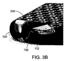
任意に、バルーンの膨張時、メッシュはバルーンの片面にのみ配置される。あるいは、メッシュはバルーンの縁部分に巻き付いて、バルーンの裏面、すなわち膨張チューブを取り付ける面とは反対側の面に、好ましくはバルーンの外縁部の近くにのみ取り付けられる。これにより、バルーンが膨張時にメッシュを全面的に支持することが可能となり、およびメッシュの縁部ならびに中心を展開させることが可能となる。任意に、この実施形態では、メッシュはバルーンに部分的に巻き付き、メッシュの主要部分はバルーンの前面、すなわちヘルニアに面する面にある。 Optionally, when the balloon is inflated, the mesh is only placed on one side of the balloon. Alternatively, the mesh wraps around the edge of the balloon and is attached only to the back side of the balloon, i.e., the surface opposite the surface to which the inflation tube is attached, preferably only near the outer edge of the balloon. This allows the balloon to fully support the mesh when inflated and allows the edges and center of the mesh to be deployed. Optionally, in this embodiment, the mesh is partially wrapped around the balloon and the main portion of the mesh is on the front surface of the balloon, ie the surface facing the hernia.
本発明の例示的な実施形態では、バルーンの内部には膨張流体のみが含まれる。ここで使用される膨張流体には、液体、ゲルおよび/またはガスが含まれる。任意に、膨張チューブはバルーンに侵入しない。 In an exemplary embodiment of the invention, the balloon contains only inflation fluid. As used herein, inflation fluids include liquids, gels and / or gases. Optionally, the inflation tube does not penetrate the balloon.
例示的な実施形態では、収縮状態でのバルーンの面積は、メッシュの面積以下である。任意に、バルーンの面積は、メッシュの面積の70%、50%、20%、10%、5%以下または任意のその間の値をとる。任意に、バルーンは、開放領域によって分離された複数の接続された部分を含み、開放領域は、バルーンの範囲の少なくとも70%、50%または30%を占める。ここで使用されるバルーンの範囲は、バルーンの最も外側の縁部によって形成された形状の範囲を指す。開放領域は、膨張時にバルーン材料によって覆われない範囲の部分を指す。任意に、バルーンの範囲はメッシュの範囲以下である。 In an exemplary embodiment, the balloon area in the deflated state is less than or equal to the mesh area. Optionally, the area of the balloon takes 70%, 50%, 20%, 10%, 5% or less of the mesh area, or any value in between. Optionally, the balloon includes a plurality of connected portions separated by an open area, the open area occupying at least 70%, 50% or 30% of the extent of the balloon. As used herein, the extent of a balloon refers to the extent of the shape formed by the outermost edge of the balloon. The open area refers to the portion of the area that is not covered by the balloon material when inflated. Optionally, the balloon range is less than or equal to the mesh range.
例示的な実施形態では、腹腔へ挿入する前に、バルーンはほぼシリンダー形状に巻かれる。任意に、バルーンは、任意に取り付けられたメッシュと共に、巻かれる前に折り畳まれて、メッシュのオプションのコーティングを保護するようにする。好ましくは、メッシュの非接着性コーティング部分が折り重ねられる。バルーンの、コーティングされたメッシュを折り畳むことによって、腹腔で展開されるときにメッシュの正しい面が腹壁に向くようにできることに留意されたい。任意に、バルーンは、折り畳み時にバルーンの2つの折り畳まれた部分が重ならないように非対称的な形状を有し、それにより、折り畳まれたバルーンの構成を比較的薄くする。これにより、折り畳まれたバルーンの構造を小さくできる。 In an exemplary embodiment, the balloon is rolled into a generally cylindrical shape prior to insertion into the abdominal cavity. Optionally, the balloon, along with an optionally attached mesh, is folded before being rolled to protect the optional coating on the mesh. Preferably, the non-adhesive coating portion of the mesh is folded. Note that by folding the coated mesh of the balloon, the correct face of the mesh faces the abdominal wall when deployed in the abdominal cavity. Optionally, the balloon has an asymmetric shape so that the two folded portions of the balloon do not overlap when folded, thereby making the folded balloon configuration relatively thin. Thereby, the structure of the folded balloon can be made small.
その代わりにまたはそれに加えて、バルーンは、分岐形状、偏心形状、同心形状、閉鎖形状、開放形状、対称形状、またはそれらのいずれかの組み合わせのいずれか1つを有し得る。 Alternatively or in addition, the balloon may have any one of a bifurcated shape, an eccentric shape, a concentric shape, a closed shape, an open shape, a symmetrical shape, or any combination thereof.
本発明の一部の実施形態の態様は、体内への挿入前に外科材料を巻き付けるための巻取装置に関する。任意に、外科材料は、メッシュおよびそれに取り付けられたバルーンを含む。 An aspect of some embodiments of the invention relates to a winding device for winding surgical material prior to insertion into the body. Optionally, the surgical material includes a mesh and a balloon attached thereto.
例示的な実施形態では、巻取装置は、巻き付けられた外科材料を体内へ挿入するための套管針を介した挿入に適合されている。例示的な実施形態では、巻取装置は2つの接合ロッドを含み、それらは、外科材料をそれらの間に配置するために分離できる。例示的な実施形態では、巻取装置はさらに、ロッドの遠位端にハンドルを含む。好ましくは、巻取装置はさらに、ロッドの近位端につまみを含む。好ましくは、つまみは、ロッドを分離するために取り外し可能な2つの付属部分を含み、それらの間に外科材料を挿入できる。 In an exemplary embodiment, the winding device is adapted for insertion via a trocar for inserting the wound surgical material into the body. In an exemplary embodiment, the winding device includes two joining rods that can be separated to place surgical material therebetween. In an exemplary embodiment, the winding device further includes a handle at the distal end of the rod. Preferably, the winding device further includes a knob at the proximal end of the rod. Preferably, the knob includes two attachment portions that are removable to separate the rod, between which surgical material can be inserted.
任意に、ハンドルはアンカーに変形させることができ、アンカーは、外科材料をロッドに巻き付けるためのベースの機能を果たす。好ましくは、アンカーによって、外科医または他の人は単独で、補助を必要とせずに外科材料をロッドに巻き付けることができる。任意に、ハンドルは2つの平行部分を含み、それらは、中心部分に接続され、かつアンカーを形成するように動かすことができる。任意に、アンカーはX字形、矩形、三角形または任意の他の形状を有する。任意に、アンカーの平行部分は、アンカーをトレイまたは他のベースに固着させるためのスリットを含む。例示的な実施形態では、ハンドルを遠位端から取り外し、ロッドの近位端のつまみに取り付ける。これにより、体内へ挿入するために巻取装置を掴むこと、ならびに体内で解放する外科材料の経路を空けることを容易にできる。 Optionally, the handle can be transformed into an anchor, which serves as a base for wrapping the surgical material around the rod. Preferably, the anchor allows the surgeon or other person alone to wrap the surgical material around the rod without the need for assistance. Optionally, the handle includes two parallel parts, which are connected to the central part and can be moved to form an anchor. Optionally, the anchor has an X shape, a rectangle, a triangle or any other shape. Optionally, the parallel portion of the anchor includes a slit for securing the anchor to a tray or other base. In an exemplary embodiment, the handle is removed from the distal end and attached to the knob at the proximal end of the rod. This facilitates grasping the take-up device for insertion into the body and opening the path for surgical material to be released in the body.
例示的な実施形態では、巻取装置はさらに、ハンドルとロッドとの間に軸受けを含み、ハンドルまたはアンカーを動かすことなくロッドを回すことができるようにする。任意に、ハンドルとロッドとの間の継手は、ハンドルがアンカーの機能を果たすときに外科材料をロッドに簡単に巻き付けるようにするために、曲がることができる。 In an exemplary embodiment, the winding device further includes a bearing between the handle and the rod so that the rod can be turned without moving the handle or anchor. Optionally, the joint between the handle and the rod can be bent to make it easier to wrap the surgical material around the rod when the handle serves as an anchor.
よりよく理解するために、本発明の一部の実施形態を図1〜11に示す。 For better understanding, some embodiments of the present invention are shown in FIGS.
本発明の少なくとも1つの実施形態を詳細に説明する前に、本発明は必ずしも、以下の説明および/または図面および/または例に記載の構成部品の構成および配置および/または方法の詳細への適用に限定されないことを理解されたい。本発明は他の実施形態が可能であり、または様々な方法で実施するもしくは行うことができる。 Before describing in detail at least one embodiment of the present invention, the present invention is not necessarily limited to the following description and / or configuration and arrangement of components and / or method details described in the drawings and / or examples. It should be understood that this is not a limitation. The invention is capable of other embodiments or of being practiced or carried out in various ways.
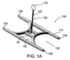
図1Aに、本発明の例示的な実施形態によるバルーン100を示す。バルーン100は、膨張式本体110および膨張チューブ120を含む。本発明の例示的な実施形態では、本体110は、図1Bに示すようにバルーンが折り畳まれているときには非対称的な形状を有し、バルーンの2つの折り畳まれた部分は重なり合わない。重なり合わない部分によって、折り畳まれたバルーンの構成を比較的薄くする。これは、套管針を通して腹腔内に挿入するためにバルーンを巻いているときに有利である。腹腔鏡用開口または套管針を通して挿入する場合には、小型のデバイスの方が簡単であることはよく知られている。折り畳まれたバルーンを比較的薄い構成とすることによって、巻いたロールの構成を薄くすることができ、手順を助ける。
FIG. 1A shows a
膨張式本体110を、開放領域150によって分離された複数の接続された部分を有するように示す。任意に、開放領域は、バルーンの範囲の70%超、50%超または20%超を占める。バルーンの範囲は、バルーンの最も外側の縁部、例えば図1Aの縁部109などによって形成された形状の範囲と定義する。その代わりにまたはそれに加えて、開放領域は30%超、50%超、70%超、または収縮および/または膨張状態においてバルーンの領域の任意のその間の値をとる。バルーンの開放領域はまた、上述のように、腹腔に挿入するために巻かれたバルーンの構成を薄くする助けをする。
The
例示的な実施形態では、膨張チューブ120は可撓性である。その代わりにまたはそれに加えて、膨張チューブは伸縮性がある。好ましくは膨張チューブ120を膨張式本体110の中心領域に取り付ける。任意に、膨張チューブ120を本体110の外面に取り付ける。膨張チューブ120はバルーンに侵入せず、本体110の内部には膨張流体のみが含まれる。
In the exemplary embodiment,
図1Cは、本発明の例示的な実施形態による膨張チューブ120のより詳細な図である。膨張チューブ120は、チューブ122およびオプションの把持用付属物124を含む。把持用付属物124は、任意にヘルニアまたはヘルニアを取り囲む組織の小さな穴を経由して挿入された縫合糸通し具または他の把持具を介して、外科医が腹腔内で膨張チューブを把持するのを支援するように適合されている。任意に、図1Cに示すように、把持用付属物124はループである。あるいは、把持用付属物124は、当該技術分野で公知の任意の他の好適な把持手段とし得る。例えば、把持用付属物124を把持するために、ロッドの端部にあるフックを使用することができる。
FIG. 1C is a more detailed view of an
任意に、膨張チューブ120はさらに、膨張チューブ120をメッシュにスムーズに貫通させるために、比較的堅固な端部126を含む。堅固な端部126は、針または任意の他の好適な鋭い要素を含み得る。好ましくは、端部126は、メッシュまたはバルーンを傷つけるほどには鋭くない。さらに、端部126は、任意に、組織、患者の腹腔の組織などを傷つけるほどには鋭くない。任意に、端部126の直径はチューブ122よりも小さい。
Optionally, the
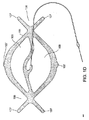
図1Dに、本発明の別の例示的な実施形態によるバルーン111を示す。この実施形態でも、バルーンは非対称的な形状である。さらに、バルーンは、バルーンに取り付けられたメッシュを支持するための最も外側の縁部107を含む一方で、大きな開放領域108をもたらし、それにより、巻かれたときにバルーンの構成を比較的薄くする。バルーン111は、バルーン100の膨張チューブと同様の膨張チューブを含み得る。
FIG. 1D shows a
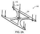
本発明の例示的な実施形態では、バルーン100または111は、図2A〜図2Hに示すように、可撓性コイルによってメッシュに取り外し可能に取り付けられる。図2Aは、複数の端部にコイル112を有するバルーン100を示す。例示的な実施形態では、バルーンは少なくとも1つのコイルを含む。任意に、バルーンは4つの端部にコイルを含む。あるいは、バルーンは追加のセットのコイル114を含み、それらは、図2Aに示すように、バルーンの端部からは距離をおいて位置決めされる。これにより、異なるセットのコイルを使用して異なるサイズのメッシュをバルーンに取り付けることが可能となる。
In an exemplary embodiment of the invention,
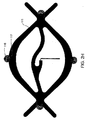
図2Bは、コイル112および114のより詳細な図である。コイル112および114をバルーン100の伸長部136に位置決めする。コイル112および114は、可撓性コイル部分130および任意選択の線形部分132からなる。任意に、コイル112および114はまた、メッシュに容易に貫通させるために、比較的堅固な要素134、例えば針または任意選択の線形部分もしくはコイル部分の尖った端部などを含む。
FIG. 2B is a more detailed view of
図2Cに示すように、コイル112は、メッシュ200を貫通するように適合されている。メッシュ200には穴202が密集している。例えば、穴は、メッシュの隣接する縦糸と横糸との間の空間であり、または穴は、メッシュを作製するファブリック内に形成されている。任意に、コイル112を作製するのに使用されたワイヤの直径は、穴202を通過するように適合されている。任意に、直径は穴202よりも小さい。任意に、膨張チューブ120の直径もまた穴202よりも小さく、膨張チューブ120は穴を通過する。
As shown in FIG. 2C, the
任意に、メッシュの片面がコーティングされている場合、コーティング面をバルーンに向けるように注意する必要がある。これは、メッシュのコーティング面をヘルニアに向けてはいけないためである。 Optionally, if one side of the mesh is coated, care must be taken to direct the coated side towards the balloon. This is because the coating surface of the mesh should not be directed to the hernia.
コイル部分130は伸縮自在および/または可撓性であり、かつ任意に図2Dに示すようにメッシュ200に貫通させるために伸長できる。伸長時には、コイル部分130の直径は小さくなり、それにより、メッシュへの貫通を支援する。好ましくは、コイル部分130は伸縮自在であり、図2Eに示すように、メッシュ200を通過した後にはそれらの元のコイル形状に戻る。コイル部分130の可撓性の特性によってまた、メッシュからバルーンを容易に取り外すことができるようになる。バルーンを引っ張ると、コイル部分130は伸長してメッシュ200の穴202を通過し、それにより、メッシュ200を傷つけることなくメッシュ200からバルーン100を取り除く。
The
本発明の例示的な実施形態では、図2Fに示すように、メッシュを貫通した後に線形部分132および/または堅固な要素134を切断する。任意に、膨張チューブ120の堅固な要素126はまた、メッシュに通された後で切断される。
In an exemplary embodiment of the invention,
図2Gおよび図2Hは、本発明の別の例示的な実施形態に従ってメッシュをバルーンに取り付けるために使用することができる、異なるコイル115を示す。コイル115はまた任意に、上述のコイル112の堅固な要素134と同様の、メッシュに通すための比較的堅固な要素117を含む。任意に、コイル115はさらに、図2Dに示すように、バルーンに取り付けられている垂直要素118を含む。垂直要素118は好ましくはコイルがバルーンから滑って外れないようにする。図2Hはバルーン111を示すものの、コイル112および115の双方とも、バルーン110および111または当該技術分野で公知の任意の他のバルーンにも使用できることに留意されたい。
2G and 2H illustrate
コイル115は、ロール状のバルーンを薄い構成にするのに有利とし得る平坦な構成を有する。
The
図3Aおよび図3Bに、バルーン100をメッシュ200に取り外し可能に取り付けるための構成の、別の例示的な実施形態を示す。この実施形態では、メッシュ200はバルーンの縁部に巻き付いて、コイル、例えばコイル112または115に取り付けられる。コイルは、図3Bに示すように、バルーンの背面、すなわちチューブが延出する側とは反対側から延出している。この実施形態によって、図2に示す実施形態とは対照的に、メッシュをしっかりと支持することが可能になる。任意に図3の実施形態では、メッシュの主要部分は、腹壁に面するバルーンの前面にあり、メッシュは部分的にバルーンに巻き付くようになっている。
FIGS. 3A and 3B illustrate another exemplary embodiment of a configuration for removably attaching the
図2および図3は、バルーンをメッシュに取り外し可能に取り付ける例示的な手段にすぎないことに留意されたい。当該技術分野で公知の任意の他の固定手段、縫合糸、Velcro、接着剤および/または2008年10月22日出願のPCT/IL2008/001381号(国際公開第2009/050717号として公開。その開示を本願明細書に援用する)に説明されている任意の他の固定手段などを用いてもよい。 It should be noted that FIGS. 2 and 3 are merely exemplary means for removably attaching the balloon to the mesh. Any other fixation means known in the art, sutures, Velcro, adhesives and / or PCT / IL2008 / 001381 filed Oct. 22, 2008 (published as WO 2009/050717. Disclosure thereof. May be used as well as any other fixing means described in the present specification.
図4Aおよび図4Bは、本発明の例示的な実施形態による、折り畳まれたバルーンおよびメッシュの概略図である。メッシュ200およびバルーン100は、膨張チューブ120が折り畳み構造の外側になるように、任意に折り畳まれている。次いで可撓性膨張チューブ120を折り畳みに対して平行に位置決めして、下記で図5〜図7を参照して説明するように、バルーンおよびメッシュと共に巻かれるようにする。任意に、メッシュは非接着性コーティングを有し、メッシュは、半分にされた一方の側のコーティング面が、他方の側のコーティング面に面するように、折り畳まれる。
4A and 4B are schematic views of a folded balloon and mesh, according to an illustrative embodiment of the invention. The
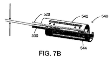
図5は、本発明の例示的な実施形態による巻取装置500の概略図である。巻取装置は、2つの密接して位置決めされたロッド520および530を含む。ロッド520および530の遠位端522にはハンドル510を取り付けることができる。任意に、ハンドル510はT字形である。例示的な実施形態では、ハンドル510の上部は2つの部分512および514を含み、図8に示すようにアンカーの形に展開することができる。アンカーは、X字形、矩形、三角形またはそれらの形状の任意の組み合わせを有し得る。
FIG. 5 is a schematic diagram of a winding
ハンドル510は任意にさらに軸受け518を含み、軸受けによって、ハンドル510を回転させることなく、ロッド520および530を回すことができる。ハンドル部分512、514と軸受け518との間にはたわみ継手516が好ましくは設けられ、ハンドル部分512、514を軸受け518に対して動かすことができるようにし、それにより、ロッド520、530とハンドル510との間の角度を変更することができる。
The
ロッド520、530の近位端524には、好ましくは、ロッドの近位端を簡単に把持するためのつまみ540がある。
The
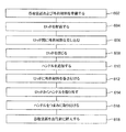
図6は、図5の巻取装置に外科材料を巻き付けるための方法のフローチャートである。図7A〜図7Iは、図6のフローチャートにリストした作業の概略図である。 FIG. 6 is a flowchart of a method for winding surgical material around the winding device of FIG. 7A-7I are schematic diagrams of the operations listed in the flowchart of FIG.
602では、図7Aに示すように巻取装置500および外科材料200が準備される。外科材料200は、これ以降メッシュ200と称すが、任意の他の外科材料も使用できることを理解されたい。例えば図4Bに示すような、折り畳まれたバルーンが、メッシュに取り付けられる。
At 602, a winding
604では、しっかりと結びつけられたロッド520および530は、それらの間にメッシュ200を差し込むために、任意につまみ540によって解放される。任意に、つまみ540は、解放可能な2つの部分542および544からなり、それにより、図7Bに示すようにロッド520と530との間に開口をもたらす。
At 604, the tightly coupled
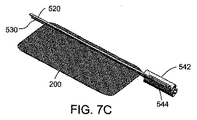
606では、図7Cに示すように、ロッド520および530の間を通してメッシュ200の縁部を差し込む。任意に、メッシュの隅部のみをロッドに差し込む。608では、ロッド520および530をくっつけるように押して、ロッド間にメッシュ200がしっかりと挟まれるようにする。図7Dに、元の位置に戻され、それによりロッド520と530との間の開口を閉じるつまみ540の2つの端部542および544を示す。
At 606, the edge of
610では、ハンドル510を、任意にロッド520、530の遠位端522に取り付ける。これにより、612では、ロッド520および530を回すときにハンドルを把持することが簡単になる。
At 610, a
概して、メッシュ200をロッド520、530に巻き付けるためには3本の手が必要である。第1の手は、つまみ540を回すことによってロッド520を回すために使用する。第2の手は、メッシュを保持して、巻いた構成にしわができないようにするために使用し、および第3の手は、ハンドル510を把持して巻取プロセス中に巻取装置500を安定させるために使用する必要がある。従来の巻取装置では、ハンドル510がロッドと一緒に回ってしまうので、助手が巻取プロセス中にハンドルを保持することが困難であった。
Generally, three hands are required to wrap the
例示的な実施形態では、ロッド520、530とハンドル510との間に軸受け518が設けられている場合、ハンドル510を動かすことなくロッドを回すことができる。この実施形態では、メッシュ200を巻き付ける際に助手が外科医を助けることができる。一人が片手でつまみを回すことによってロッドを回す一方、もう片方の手でメッシュを保持して、巻いた構成にしわができないようにする。他の人がハンドル510を保持して、巻取装置を安定させることができる。あるいは、図8A〜図8Dを参照して以下説明するように、ハンドル510は、第3の手を必要としないように、アンカーとしての機能も果たし得る。
In the exemplary embodiment, if a bearing 518 is provided between the
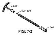
図7Fに、メッシュ200がロッド520および530に巻き付けられているときの巻取装置500を示す。614では、メッシュ200を巻き付けた後、ハンドル510はロッドから取り外されて、メッシュ200を腹腔内で解放するための経路を空ける。これを図7Gに示す。
FIG. 7F shows the winding
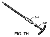
616では、例示的な実施形態において、図7Hに示すように、その後ハンドル510をつまみ540に取り付ける。ハンドル510をつまみ540に取り付けることにより、より良好な把持手段が提供され、套管針を通した腹腔鏡用開口への巻取装置500の操作、およびその後の腹腔へのメッシュの解放を支援する。図7Iに示すように、任意に、つまみ540はその端部に突起546を有し、その突起はハンドルのアパーチャ548に適合するので、ハンドル510をつまみ540に取り付けることができる。あるいは、ネジ、velcroまたは接着剤のような当該技術分野で公知の任意の他の取付手段を使用してもよい。
At 616, in an exemplary embodiment, the
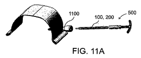
618では、図11Aに示すように、メッシュ200が巻き付けられた巻取装置500を、套管針を通して腹腔に挿入する。
In 618, as shown in FIG. 11A, the winding
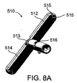
図8A〜図8Dは、本発明の例示的な実施形態に従ってアンカーとして使用されるハンドル510を有する巻取装置800の概略図である。図8Aは、図7Eとは異なる、任意にT字形のハンドル510の図である。ハンドル510は、中心513でヒンジによって取り付けられた2つの部分512および514を含む。図8Aでは、部分512および514は互いに対して平行に配置され、単一のアームを形成している。部分512および514を、互いに対して離れるように回転することができ、かつ、図8Bに示すようなX字形を形成するように互いに対して実質的に垂直に向くようにできる。アンカーとしての機能を果たすのに好適な任意の他の形状、例えば矩形または三角形を使用してもよいことに留意されたい。
8A-8D are schematic views of a winding
任意に、部分512、514はまたスリット515を含む。図8Dに示すように、スリット515は任意にハンドルをトレイ810または他のベースに固着するために使用される。トレイ810の縁部がスリット515に入り、それによりハンドル510をトレイ810に固着させる。
Optionally,
例示的な実施形態では、さらに、部分512、514と軸受け518との間にはたわみ継手516が設けられる。例えば図8Cに示すように、たわみ継手516によってハンドル510を軸受け518に対して回転させ、それによりロッド520、530とハンドル510との間の角度を変更することができる。これは、巻取プロセス中にハンドル510を固着させ、巻取装置500を安定させることを可能にする別の特徴である。この実施形態では、外科医は、外科材料をロッド520、530に巻き付ける際に、いかなる支援も必要としない。
In the exemplary embodiment, a flexible joint 516 is further provided between the
巻取装置500および800は例示にすぎず、メッシュ200およびバルーン100は巻取装置がなくとも、または当該技術分野で公知の任意の他の巻取装置を用いずとも巻き付けることができることに留意されたい。例えば、図9A〜9図Nに、本発明の別の例示的な実施形態による別の巻取装置を示す。
It is noted that the winding
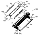
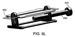
図9Aは、本発明の例示的な実施形態による巻取装置900の概略図である。巻取装置900は、外科材料100および/または200を収容して巻き取るように適合されている。巻取装置900は、2つのロッド901によって接続された2つのベース902からなる。図9Bにベース902のより詳細な図を示す。
FIG. 9A is a schematic diagram of a winding
ベース902は底部層903および上部905を有する。任意に、ベース902は、上部905から延出するトレイ910を含み、その上に外科材料を配置できる。ベース902はまた、好ましくは、図9Aに示すようにスプール904を配置するための上部穴906および下部穴908を含む。例示的な実施形態では、装置900は2つのスプール904からなり、それらの間に外科材料を配置してスプール上に巻き付ける。穴906と908との間には任意に弾性ストッパ912を設ける。弾性ストッパ912は、図9Aに示すようにスプール904を上部穴906に保持し、かつ、スプール904が、下方に押されることによって上部穴906から下部穴908に通過できるように、上部から押されると、開放するように適合されている。
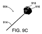
図9Cは、ロッド914およびつまみ916を描く、スプール904のより詳細な図である。つまみ916には、好ましくは切り込みが入れられており、第2のスプール920のロッド926(図9Gに図示)を切り込みに差し込むことができるようにされている。任意に、図9Cに示すように、つまみ916は丸い形状をしている。あるいは、つまみ916は六角形または他の形状をしている。
FIG. 9C is a more detailed view of
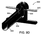
図9Dに、スプール904が上部穴906に配置され、かつスロット付きチューブ930が下部穴908の下に配置されている巻取装置900を示す。スロット付きチューブ930は、下部穴908に押し込まれたときに、外科材料を巻き付けられた後のスプール904を受けるように適合されている。任意に、チューブ930は弾性があり、バネのようなものである。チューブ930の端部932を溝934に位置決めして、チューブ930を開放位置に保持する。図9Lに示し、以下説明するように、チューブ930が下に押されると、端部932が溝934から解放され、チューブ930が閉じられる。
FIG. 9D shows the winding
巻取装置900は、以下説明するように、外科材料、例えばメッシュ200および/またはバルーン100を巻き付けるように適合されている。外科材料を、図9Aに示すパッケージ950に挿入する。パッケージ950は、巻き付け手順中、外科材料100、200を適所に保持するように適合されており、好ましくは薄いポリプロピレン製である。任意に、パッケージ950は、外科材料を保持するように適合された、ナイロンまたは金属などの任意の他の好適な材料または材料の組み合わせから作製される。パッケージ950は好ましくは、ベース902の上部905を通して挿入されるように適合した形状のアパーチャ952と、トレイ910に位置決めされるように適合された伸長部954とを含む。任意に、パッケージ950は、外科材料100、200の上部に配置され、外科材料を包み込まない。あるいは、パッケージ伸長部954はスリット955を含み、そのスリットに外科材料を通すことによって、外科材料を適所に固定する。
Winding
ここで図9E〜図9Nを参照すると、装置900によって外科材料を巻き付ける手順を示す。
Referring now to FIGS. 9E-9N, a procedure for winding surgical material with the
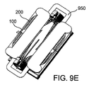
図9Eに、外科材料100、200がトレイ910(パッケージに覆われていて見えない)に位置決めされている開始位置にある巻取装置900を示す。次いで、図9Fに示すように、第2のスプール920を装置900に加えて、図9Gに示すように、外科材料をスプール920と904との間に位置決めするようにする。スプール920は好ましくはその端部における2つのつまみを有し、装置900の開口924に挿入されるように適合されている。任意に、図9Gに示すようにスプール920および904を位置決めするとき、スプールのロッド間に隙間がなくなるように、装置を構成する。
FIG. 9E shows the winding
次いで、図9Hに示すように、つまみ922を回して外科材料100、200をスプール904および920に巻き付ける。図9Iに、上部穴906に位置決めされている間の、スプール904および920に巻き付けられた外科材料を示す。
Then, as shown in FIG. 9H, the
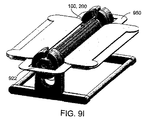
次に、図9Jに示すように、スプール904および920を下部穴908のトレイ930に押す。ここで、図9Kに示すように、スプールはさらに下方に押され、それによりトレイ930も下方に押され、それにより、トレイ930の縁部932が溝934から解放され、チューブ930が、スプール904、920に巻き付けられた外科材料100、200を内部に有した状態で閉じられる。この時点で、つまみ916および922をスプール904および920の一方の端部から取り外す。これにより、図9Lに示すようにチューブ930を巻取装置900から取り外すことが可能となる。図9Mは、外科材料100、200が内部で巻かれているチューブ930の、より詳細な図である。例示的な実施形態では、チューブ930は、任意に套管針を通して体内に挿入されるように適合されている。あるいは、巻き付けられた外科材料100、200は、腹腔に挿入する前にチューブ930および/またはスプール904、920から取り外される。任意に、外科医は、図9Iに示す段階の後で、巻き付けられた外科材料100、200を解放して、任意に套管針を通して体内に挿入することもある。その代わりにまたはそれに加えて、つまみ922の一方も長いハンドルを備えて、外科材料100、200の巻き付けおよび挿入を容易にする。
Next, as shown in FIG. 9J, the
図10は、本発明の例示的な実施形態によるヘルニアの処置方法のフローチャートである。図11A〜図11Iは、図10に概要を述べた方法の作業の概略図である。 FIG. 10 is a flowchart of a method for treating a hernia according to an exemplary embodiment of the present invention. 11A-11I are schematic views of the operation of the method outlined in FIG.
1020では、メッシュおよびバルーンを、腹腔鏡用開口および/または套管針を通して腹腔に挿入する。任意に、図11Aに示すように、メッシュ/パッチ200およびバルーン/膨張性容器100を、套管針1100を通して挿入される巻取装置500もしくは800または他の何らかの巻取装置に巻き付けられている間に、挿入する。あるいは、図11Bに示すように、異なる器具を使用してメッシュおよびバルーンを運ぶ。図11Aおよび図11Bでは、バルーンの周りにメッシュが巻き付けられているため、バルーン100は見えない。
At 1020, the mesh and balloon are inserted into the abdominal cavity through a laparoscopic opening and / or trocar. Optionally, as shown in FIG. 11A, while the mesh /
図11Bに示すように、任意に、第2の套管針1110が使用される。第2の套管針1110は、好ましくは内視鏡などの光学素子を挿入するために使用され、外科医が腹腔内部を観察できるようにする。任意に、套管針1110を、把持装置などの腹腔鏡手術道具のために使用する。
Optionally, a
概して、追加的なヘルニア欠損を生じないようにするために、可能な限り直径の小さい開口を形成することが好ましい。縫合糸通し具またはチューブキャッチャ(tube catcher)と比べて、套管針の直径は通常3〜18mmと比較的大きい。それゆえ、套管針1100および1110は好ましくは腹部側の腹腔鏡用開口を通して挿入され、既に弱くなっている欠損部の壁を損傷させないようにする。
In general, it is preferable to make the opening as small as possible in order to avoid additional hernia defects. Compared to a suture threader or tube catcher, the diameter of the trocar is usually relatively large, 3-18 mm. Therefore, the
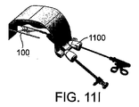
1030では、図11Cに示すように、メッシュおよびバルーンは腹腔内部で解放される。任意に、図11Dに示すように、メッシュが巻取装置から滑らない場合、つまみ540の2つの部分542、544を解放する。これにより、ロッド520と530との間に開口を形成し、かつメッシュおよびバルーンがロッドから腹腔に滑るのを支援する。
At 1030, the mesh and balloon are released inside the abdominal cavity, as shown in FIG. 11C. Optionally, as shown in FIG. 11D, if the mesh does not slip from the winder, the two
1040では、腹腔内で膨張チューブを把持する。好ましくは、図11Eに示すように、縫合糸通し具などの掴持装置1130を、腹壁の小さな穴を通して挿入して、膨張チューブを捕らえる。例示的な縫合糸通し具は、Covidien - Auto Suture(商標)製のEndoClose(商標)である。例示的な実施形態では、把持装置は腹壁に開口1140を形成し、その開口は、腹腔鏡用開口よりも小さく、腹部欠損に形成される場合でも腹部欠損に何の危険もない。任意に、開口1140の直径は1、2、2.5または2.9mm以下である。開口1140は、ヘルニア欠損を通してまたはヘルニア欠損を囲む組織に形成することができる。
At 1040, the inflation tube is grasped within the abdominal cavity. Preferably, as shown in FIG. 11E, a grasping
任意に、把持装置1120も套管針1100を通して挿入され、膨張チューブを掴持装置1130にもたらす支援をする。あるいは、光学素子は套管針1100を通り、および把持装置は第2の套管針1110を通ることができる。図11Eに示すように、次いで、1050では、掴持装置1130は膨張チューブ120のループ124を捕らえて、開口1140を通して腹腔から膨張チューブを引っ張る。任意に、掴持装置1130はその端部にフック(図示せず)を有し、そのフックはループ124を通るように適合されている。あるいは、他の把持手段、例えば縫合糸通し具を使用して、ループ124または膨張チューブ120の任意の他の部分を捕らえることができる。
Optionally, a
1055では、メッシュおよびバルーンをヘルニア欠損に位置決めする。例示的な実施形態では、メッシュが取り付けられたバルーンを、膨張チューブ120を引っ張ることによって位置決めする。膨張チューブ120を引っ張ることによって、メッシュ200およびバルーン100は腹壁近くに位置決めされ、実質的に中心がヘルニア欠損にあるようにされる。任意に、穴1140はヘルニア欠損を通して形成され、それにより、欠損にメッシュの中心をもたらすことを支援する。
At 1055, the mesh and balloon are positioned at the hernia defect. In the exemplary embodiment, the mesh-attached balloon is positioned by pulling the
あるいは、例えば欠損部位が非常に薄い場合、穴1140は、通常、より厚みのある欠損を囲む組織に形成される。この場合、メッシュの中心は正確に欠損にもたらされないであろうが、依然としてメッシュはヘルニア欠損を覆っている必要がある。任意に、膨張チューブを回転させることによってバルーンおよびメッシュの向きを決定することができ、それにより、メッシュがヘルニア欠損を完全に覆うことを保証する。それゆえ、体外から膨張チューブを引っ張る(かつ任意にそれを回転させる)ことによって、所望の予め定められた位置での、便利で正確なメッシュの位置決めおよび中心合わせが可能となる。
Alternatively, for example, if the defect site is very thin, the
バルーンの中心領域における膨張チューブ120の位置は、膨張チューブによってメッシュおよびバルーンを中心合わせするのに便利である。あるいは、膨張チューブはバルーンの中心領域に位置決めされず、ある程度中心から外れており、それは、欠損の周囲に開口1140が形成される場合に有利であり、それにより、メッシュがより広い面積でヘルニア欠損を覆うことが可能となる。
The position of the
任意に、腹腔から膨張チューブを引き抜いた後、膨張チューブからループ124を切り取り、それにより、膨張流体を受け入れるためにチューブを開く。
Optionally, after withdrawing the inflation tube from the abdominal cavity, the
例示的な実施形態では、膨張チューブには、任意に掴持装置1130を備える締結アダプタ1132が配置され、膨張チューブが滑って腹腔に戻らないようにする。膨張チューブを適所に締結することによって、外科医は、バルーンおよびメッシュが腹腔で位置決めされるべき所望の高さも制御することができる。任意に、クランプやケリー鉗子などの任意の他の締結手段を使用して、膨張チューブを適所に締結できる。次いで、1060では、掴持装置1130を解放し、膨張チューブ120に注入装置またはポンプ1150を取り付けてバルーン100を膨張させる。任意に、膨張流体は、空気またはCO2などのガスまたはガス混合物である。あるいは、生理食塩水または任意の他の液体などの任意の他の膨張流体を使用してもよい。バルーン100が膨張することによって、バルーンは展開する。バルーンはメッシュに取り付けられているため、バルーンが展開することによって、メッシュに推進力をもたらし、図11Gに示すようにメッシュも展開して拡がる。
In the exemplary embodiment, the inflation tube is provided with a
バルーン100およびメッシュ200は腹壁の近くに位置決めされ、かつ腹部欠損を通してまたは欠損の周辺組織に開口1140が形成されたとき、メッシュは、ヘルニア欠損を修復するための予め定められた位置にある。任意に、メッシュを必要な位置および向きに配置するように膨張チューブ120を引っ張る。
When the
1070では、メッシュ200は腹壁に取り付けられる。例示的な実施形態では、図11Hに示すように、メッシュを腹壁に固定するために、套管針1100を通してタッカ1160が挿入される。タッカ1160を、CovidienのProTack(商標)、DavolまたはDavol* PermaSorb(商標)のSORBAFIx(商標)などの当該技術分野で公知の任意の好適なタッカとし得る。あるいは、タッカは第2の套管針1110を通して挿入してもよく、光学素子は套管針1100を通して挿入する。その代わりにまたはそれに加えて、メッシュ200を腹壁に取り付けるために、ピン、爪、縫合糸、接着材料または当該技術分野で公知の任意の他の固定手段を使用することができる。
At 1070, the
例示的な実施形態では、バルーンの範囲全体はメッシュの範囲であるかまたはほぼ相当し得る一方、バルーン100の面積はメッシュ200の面積よりも実質的に小さい。任意に、バルーン100の固体面積はメッシュ200の面積の10%、20%、30%または50%未満である。任意に、バルーンは、開放領域によって分離された複数の接続された部分を含み、開放領域は、その収縮状態においてバルーンの面積の30%、50%または70%超を占める。これにより、バルーンはメッシュを支える一方、依然としてメッシュよりも実質的に小さな面積を有することができる。任意に、バルーンの範囲はまたメッシュの範囲よりも小さい。あるいは、バルーンの範囲はメッシュの範囲よりも大きくてもよい。
In an exemplary embodiment, the entire balloon area may be or substantially correspond to the mesh area, while the area of the
任意に、前記バルーンを分岐形状、偏心形状、同心形状、「H」字形状、ひし形状、対称形状、非対称的な形状、開放形状、閉鎖形状またはそれらのいずれかの組み合わせによって特徴づける。 Optionally, the balloon is characterized by a bifurcated shape, an eccentric shape, a concentric shape, an “H” shape, a rhombus shape, a symmetric shape, an asymmetric shape, an open shape, a closed shape, or any combination thereof.
バルーンの面積はメッシュの面積よりも実質的に小さく、メッシュの中心部分のほとんどにバルーンの背面からアクセスできるため、バルーンが依然としてメッシュに取り付けられている状態でも、外科医は、バルーンを収縮させたりまたは損傷させたりすることなくバルーンの大きな開放領域を通して比較的自由にメッシュを腹腔に取り付けることができる。 The balloon area is substantially smaller than the mesh area and most of the central part of the mesh is accessible from the back of the balloon, so that even when the balloon is still attached to the mesh, the surgeon can deflate the balloon or The mesh can be attached to the abdominal cavity relatively freely through the large open area of the balloon without being damaged.
この方法論により、メッシュを腹壁に取り付けている間、バルーンによるメッシュの支持、およびバルーンによるメッシュの継続的で確実な配置が可能となる。継続的で確実な配置はまた、膨張チューブを適所に保持する締結アダプタによってももたらされる。バルーンは大きな開放領域を有し得るため、バルーンを腹壁に取り付けることなく、およびバルーンをメッシュから切り離すことなく、メッシュを腹壁にしっかりと固定することができる。任意に、バルーンの範囲はメッシュよりも小さいため、メッシュの縁部を腹壁に取り付けることができる一方、バルーンは依然としてメッシュに取り付けられている。 This methodology allows for support of the mesh by the balloon and continuous and reliable placement of the mesh by the balloon while the mesh is attached to the abdominal wall. Continuous and secure placement is also provided by a fastening adapter that holds the inflation tube in place. Because the balloon can have a large open area, the mesh can be secured to the abdominal wall without attaching the balloon to the abdominal wall and without detaching the balloon from the mesh. Optionally, the extent of the balloon is smaller than the mesh, so the edge of the mesh can be attached to the abdominal wall, while the balloon is still attached to the mesh.
任意に、1080では、メッシュを腹壁に取り付けた後、バルーンは収縮されてメッシュから取り外される。例示的な実施形態では、バルーンは、膨張チューブを切断することによって収縮される。別の例示的な実施形態では、注入装置1150が膨張チューブ120から分離されるので、バルーンを収縮させる。あるいは、注入装置1150を、バルーンを積極的に収縮させるために使用する。これは、注入装置1150で弁の方向を変更するか、シリンジ様の注入装置のプランジャを引くか、またはポンプの方向を変更するかのいずれかによって実施できる。例示的な実施形態では、図11Iに示すように、バルーンをメッシュから離すように引っ張ることによってバルーンを取り除く。
Optionally, at 1080, after attaching the mesh to the abdominal wall, the balloon is deflated and removed from the mesh. In an exemplary embodiment, the balloon is deflated by cutting the inflation tube. In another exemplary embodiment, since the
任意に、膨張チューブが開口1140を通して体外に配置されている間に、膨張チューブ120は、収縮後にバルーンから切断される。任意に、膨張チューブが可能な限りバルーンに近い個所で切断されるように、膨張チューブ120は伸長されてから切断される。これは、切断後に、体外にあるチューブの汚染されたどの部分も再び体内に入ることがないようにし、腹腔の汚染を回避するために好ましい。あるいは、膨張チューブ120は、套管針1100または套管針切開を通してバルーン100と一緒に取り除かれる。
Optionally, the
任意に、バルーンは、腹壁にメッシュをしっかりと固定する前にメッシュから取り外される。このオプションはあまり好ましくない。なぜなら、バルーンは、メッシュに接続されるとき、メッシュを支持し、かつメッシュを適所に保持するためである。それゆえ、固定手順中、バルーンは好ましくは膨張されていて、メッシュに取り付けられている。任意に、バルーンはメッシュからの取り外し後に収縮される。 Optionally, the balloon is removed from the mesh prior to securing the mesh to the abdominal wall. This option is less preferred. This is because the balloon, when connected to the mesh, supports the mesh and holds the mesh in place. Therefore, during the fixation procedure, the balloon is preferably inflated and attached to the mesh. Optionally, the balloon is deflated after removal from the mesh.
1090では、バルーンは、套管針1100、1110または套管針切開を通して腹腔から取り除かれる。
At 1090, the balloon is removed from the abdominal cavity through a
ここで使用される用語「約」は±10%を指す。用語「含む(comprises、comprising、includes、including)」「有する(having)」およびそれらの同語源の語は、「含むがそれらに限定されない」ことを意味する。この用語は、用語「からなる」および「から実質的になる」を包含する。 The term “about” as used herein refers to ± 10%. The terms “comprises, comprising, includes, including”, “having” and their cognate terms mean “including but not limited to”. This term encompasses the terms “consisting of” and “consisting essentially of”.
語句「から本質的になる」は、追加的な要素および/またはステップが、特許請求される構成または方法の基本的かつ新規の特徴を大きく変えない場合にのみ、構成または方法が追加的な要素および/またはステップを含み得ることを意味する。 The phrase “consisting essentially of” means that an arrangement or method is an additional element only if the additional element and / or step does not significantly change the basic and novel characteristics of the claimed arrangement or method. And / or can include steps.
ここで使用される単数形「a」、「an」および「the」は、文脈において明白に示さない限り複数形も含む。例えば、用語「化合物」または「少なくとも1種の化合物」は、混合物も含めて複数の化合物を含み得る。 As used herein, the singular forms “a”, “an”, and “the” include plural referents unless the context clearly dictates otherwise. For example, the term “compound” or “at least one compound” may include a plurality of compounds, including mixtures.
用語「例示的な」は、ここでは、「例、実例または図示例となる」ことを意味して使用される。「例示的な」と説明されるいずれの実施形態も、必ずしも他の実施形態よりも好ましいまたは有利であると解釈されるものではなくおよび/または他の実施形態からの特徴を組み込むことを除外するものでもない。 The term “exemplary” is used herein to mean “become an example, instance or illustration”. Any embodiment described as "exemplary" is not necessarily to be construed as preferred or advantageous over other embodiments and / or excludes incorporating features from other embodiments. Not a thing.
用語「任意に」は、ここでは、「一部の実施形態においてもたらされ、他の実施形態ではもたらされない」ことを意味して使用される。本発明の任意の特定の実施形態は、複数の「任意の」特徴を、それらの特徴が矛盾しない限り含み得る。 The term “optionally” is used herein to mean “provided in some embodiments and not in other embodiments”. Any particular embodiment of the invention may include a plurality of “arbitrary” features as long as the features do not conflict.
この出願を通して、本発明の種々の実施形態が様々な形式で提示され得る。様々な形式の説明は、単に都合がよく簡潔にすることを目的にしたにすぎず、本発明の範囲に対する確固たる限定と解釈されるべきではないことを理解されたい。従って、範囲の説明は、可能な全ての部分範囲ならびにその範囲内の個々の数値を具体的に開示したものであると考慮されるべきである。例えば、1〜6などの範囲の説明は、1〜3、1〜4、1〜5、2〜4、2〜6、3〜6などの具体的に開示した部分範囲ならびにその範囲内の個々の数、例えば、1、2、3、4、5、および6であると考慮されるべきである。これは、範囲の幅に関わらず当てはまる。 Throughout this application, various embodiments of this invention may be presented in a variety of forms. It should be understood that the various descriptions are merely for convenience and brevity and are not to be construed as an absolute limitation on the scope of the invention. Accordingly, the description of a range should be considered to have specifically disclosed all the possible subranges as well as individual numerical values within that range. For example, the description of ranges such as 1 to 6 includes the specific disclosed subranges such as 1 to 3, 1 to 4, 1 to 5, 2 to 4, 2 to 6, 3 to 6 and the individual within the range For example, 1, 2, 3, 4, 5, and 6. This is true regardless of the width of the range.
本願明細書で数値範囲を示す場合には、示した範囲内の任意の引用した数値(少数または整数)を含むことを意味する。本願明細書では、語句、第1に示した数〜第2に示した数「の範囲」および第1に示した数「から」第2に示した数「までの範囲」は同じ意味で使われ、第1および第2に示した数ならびにその間の全ての少数および整数を含むことを意味する。 When numerical ranges are given herein, it is meant to include any cited numerical values (decimal or integer) within the indicated ranges. In the present specification, the terms “number” shown in the first to second “range” and number “from” shown in the first and “number up to” shown in the second are used interchangeably. I.e., including the numbers shown in the first and second and all decimals and integers in between.
明確にするために別個の実施形態に照らして説明される本発明の特定の特徴はまた、単一の実施形態において組み合わせて提供される場合もあることを理解されたい。反対に、簡潔にするために単一の実施形態に照らして説明される本発明の種々の特徴はまた、個別にまたはいずれかの好適な副結合において、または本発明の任意の他の説明の実施形態において好適なものとして提供される場合もある。種々の実施形態に照らして説明される特定の特徴は、実施形態がそれらの要素なしで動作不能でない限り、それらの実施形態の本質的な特徴であると考慮されるべきではない。 It should be understood that certain features of the invention described in the context of separate embodiments for clarity may also be provided in combination in a single embodiment. On the contrary, the various features of the invention described in the context of a single embodiment for the sake of brevity are also considered individually or in any suitable subcombination or any other description of the invention. In some cases, it may be provided as suitable in the embodiment. Certain features that are described in the context of various embodiments should not be considered essential features of those embodiments, unless the embodiment is inoperable without those elements.
本発明をその特定の実施形態と併せて説明したが、多くの代替例、修正例および変形例が当業者には明白であることは明らかである。従って、添付の特許請求の趣旨および広範な範囲にあるそのような全ての代替例、修正例および変形例を包含することを意図する。 While the invention has been described in conjunction with specific embodiments thereof, it is evident that many alternatives, modifications and variations will be apparent to those skilled in the art. Accordingly, it is intended to embrace all such alternatives, modifications and variations that fall within the spirit and broad scope of the appended claims.
本願明細書で述べた全ての出版物、特許および特許出願は、個々の出版物、特許または特許出願の各々が本願明細書に援用するものとして具体的にかつ個別に示されたのと同程度に、その全体が本願明細書に参照により援用される。さらに、本出願におけるいずれの参照文献の引用または指摘も、そのような参照文献が本発明の従来技術として利用できると認めたものであるとみなされるべきではない。セクションの見出しが使用される限りでは、見出しは必ずしも限定をしているものとみなされるべきではない。 All publications, patents, and patent applications mentioned in this application are the same as each individual publication, patent, or patent application is specifically and individually shown to be incorporated herein. The entirety of which is hereby incorporated by reference. In addition, citation or indication of any reference in this application shall not be construed as an admission that such reference is available as prior art to the present invention. As long as section headings are used, headings should not necessarily be considered limiting.
Claims (39)
前記バルーンに取り外し可能に取り付けられたメッシュ、
を含み、前記膨張チューブが前記メッシュを通る、ヘルニア修復装置。 An inflatable balloon having an inflation tube, wherein the inflation tube is adapted to be withdrawn from the body separately from the balloon through a proximal end attached to the balloon and an opening smaller than a laparoscopic opening An inflatable balloon having a distal end that is adapted; and a mesh removably attached to the balloon;
A hernia repair device, wherein the inflation tube passes through the mesh.
前記少なくとも1つのコイルによって前記バルーンに取り外し可能に取り付けられており、かつ前記バルーンの前記前面を実質的に覆うメッシュ、
を含み、前記膨張チューブが前記メッシュを通る、ヘルニア修復装置。 An inflatable balloon including a front surface and a back surface, the balloon including an expansion tube and at least one coil, the coil being attached to the back surface; and the removably attached to the balloon by the at least one coil And a mesh that substantially covers the front surface of the balloon;
A hernia repair device, wherein the inflation tube passes through the mesh.
前記ヘルニアにある別の開口を介して前記バルーンの前記膨張チューブの少なくとも一部分を捕らえて、前記腹部から取り除くステップ;
前記バルーンを膨張させるステップ;
前記メッシュを前記ヘルニアにおよびその近くに位置決めするように、前記膨張チューブを引っ張ることによって前記メッシュを位置決めするステップ;および
前記メッシュを、前記ヘルニアを覆って腹部内壁に取り付けるステップ
を含む、ヘルニアの修復方法。 Inserting a balloon and mesh into a subject's abdominal cavity through a laparoscopic opening, the balloon including an inflation tube passing through the mesh;
Capturing at least a portion of the inflation tube of the balloon through another opening in the hernia and removing it from the abdomen;
Inflating the balloon;
Repairing the hernia comprising: positioning the mesh by pulling the inflation tube to position the mesh at and near the hernia; and attaching the mesh to the abdominal inner wall over the hernia Method.
前記バルーンを膨張させるステップ;
前記膨張チューブを引っ張ることによって、前記メッシュを、前記ヘルニアを覆って前記腹腔に位置決めするステップ;
前記メッシュを前記腹壁に取り付けるステップ;および
前記腹部から前記バルーンを取り除くステップ
を含む、ヘルニアの修復方法。 Inserting a balloon and a mesh into a subject's abdominal cavity through a laparoscopic opening, the balloon having an inflation tube, and the mesh being removably attached to the balloon, wherein the inflation tube is Passing through the mesh, step;
Inflating the balloon;
Positioning the mesh in the abdominal cavity over the hernia by pulling the inflation tube;
Attaching the mesh to the abdominal wall; and removing the balloon from the abdomen.
次いで、前記メッシュおよびバルーンを、前記ヘルニアを覆って位置決めして、前記メッシュが前記ヘルニアに面するようにするステップ;
次いで、前記ヘルニアを囲む組織に前記メッシュを取り付けるステップ;
次いで、前記メッシュから離すように前記バルーンを引っ張り、それにより、前記メッシュから前記少なくとも1つのコイルを取り外すステップ
を含む、ヘルニアにメッシュを取り付ける方法。 Providing a balloon with attached at least one flexible coil and a mesh attached to the balloon by passing the at least one coil through the mesh;
Then positioning the mesh and balloon over the hernia so that the mesh faces the hernia;
Then attaching the mesh to the tissue surrounding the hernia;
Then, pulling the balloon away from the mesh, thereby removing the at least one coil from the mesh and attaching the mesh to the hernia.
2つの細長ロッド;
前記ロッドの前記遠位端に取り付けられたハンドルであって、前記メッシュを前記ロッドに巻き付けるときに、前記ロッドを固着するように適合されたアンカーに変換可能なハンドル;および
前記ロッドを回転させるように適合された、前記ロッドの前記近位端に取り付けられたつまみ
を含む巻取装置。 A winding device for winding a mesh around a rod,
Two elongated rods;
A handle attached to the distal end of the rod, the handle being convertible to an anchor adapted to secure the rod when the mesh is wrapped around the rod; and to rotate the rod A take-up device including a knob attached to the proximal end of the rod adapted to.
前記ロッドの前記遠位端に取り付けられたハンドル;および
前記ロッドの前記近位端に取り付けられたつまみ、
を含む巻取装置であって、前記巻取装置がさらに、前記ハンドルとロッドとの間に軸受けを含んで、前記ハンドルを動かすことなく前記ロッドを回すことができるようにしている、巻取装置。 Two elongated rods;
A handle attached to the distal end of the rod; and a knob attached to the proximal end of the rod;
A winding device further comprising a bearing between the handle and the rod so that the rod can be rotated without moving the handle. .
Applications Claiming Priority (7)
| Application Number | Priority Date | Filing Date | Title |
|---|---|---|---|
| US5101808P | 2008-05-07 | 2008-05-07 | |
| US5101708P | 2008-05-07 | 2008-05-07 | |
| US61/051,017 | 2008-05-07 | ||
| US61/051,018 | 2008-05-07 | ||
| US5821808P | 2008-06-03 | 2008-06-03 | |
| US61/058,218 | 2008-06-03 | ||
| PCT/IL2009/000469 WO2009136399A2 (en) | 2008-05-07 | 2009-05-07 | Method and apparatus for repairing a hernia |
Publications (2)
| Publication Number | Publication Date |
|---|---|
| JP2011520481A true JP2011520481A (en) | 2011-07-21 |
| JP2011520481A5 JP2011520481A5 (en) | 2012-06-21 |
Family
ID=41265106
Family Applications (1)
| Application Number | Title | Priority Date | Filing Date |
|---|---|---|---|
| JP2011508051A Pending JP2011520481A (en) | 2008-05-07 | 2009-05-07 | Hernia repair method and apparatus therefor |
Country Status (6)
| Country | Link |
|---|---|
| US (4) | US8920445B2 (en) |
| EP (1) | EP2363095B1 (en) |
| JP (1) | JP2011520481A (en) |
| CA (1) | CA2723705C (en) |
| ES (1) | ES2576079T3 (en) |
| WO (1) | WO2009136399A2 (en) |
Cited By (5)
| Publication number | Priority date | Publication date | Assignee | Title |
|---|---|---|---|---|
| JP2012066077A (en) * | 2010-09-24 | 2012-04-05 | Tyco Healthcare Group Lp | Device and method for rolling and inserting prosthetic patch into body cavity |
| JP2013066671A (en) * | 2011-09-26 | 2013-04-18 | Genzyme Japan Kk | Medical instrument |
| JP2014138727A (en) * | 2013-12-04 | 2014-07-31 | Genzyme Japan Kk | Medical instrument |
| JP2017535381A (en) * | 2014-12-01 | 2017-11-30 | シー・アール・バード・インコーポレーテッドC R Bard Incorporated | Prosthesis for repairing hernia defects |
| JPWO2018135568A1 (en) * | 2017-01-20 | 2019-11-14 | 日本ピストンリング株式会社 | Medical member and soft tissue treatment method |
Families Citing this family (16)
| Publication number | Priority date | Publication date | Assignee | Title |
|---|---|---|---|---|
| IL164591A0 (en) * | 2004-10-14 | 2005-12-18 | Hernia repair device | |
| WO2009136399A2 (en) | 2008-05-07 | 2009-11-12 | Surgical Structure Ltd. | Method and apparatus for repairing a hernia |
| EP2099385B1 (en) | 2006-11-27 | 2021-02-24 | Davol Inc. | A device especially useful for hernia repair surgeries |
| US20130190783A1 (en) * | 2007-03-15 | 2013-07-25 | Insighlra Medical, Inc. | Fibrotic band interrupter and implant introducing device |
| EP2752169B1 (en) | 2007-10-17 | 2015-10-14 | Davol, Inc. | Fixating means between a mesh and mesh deployment means especially useful for hernia repair surgeries |
| US9398944B2 (en) | 2008-02-18 | 2016-07-26 | Covidien Lp | Lock bar spring and clip for implant deployment device |
| US9393093B2 (en) | 2008-02-18 | 2016-07-19 | Covidien Lp | Clip for implant deployment device |
| EP2247245B1 (en) | 2008-02-18 | 2017-06-28 | Covidien LP | A device for deploying and attaching a patch to a biological tissue |
| US9833240B2 (en) | 2008-02-18 | 2017-12-05 | Covidien Lp | Lock bar spring and clip for implant deployment device |
| EP2358279B1 (en) | 2008-11-21 | 2020-06-24 | C.R.Bard, Inc. | Soft tissue repair prosthesis and, expandable device |
| EP2467066B1 (en) * | 2009-08-17 | 2019-03-27 | Covidien LP | Means for reversibly connecting an implant to a deployment device |
| WO2012047414A1 (en) | 2010-10-05 | 2012-04-12 | C.R. Bard, Inc. | Soft tissue repair prosthesis and expandable device |
| WO2012087112A1 (en) * | 2010-12-21 | 2012-06-28 | Erasmus University Medical Center Rotterdam | Expandable retractor for minimally invasive surgery and a method of manufacturing the same |
| EP3113720B1 (en) | 2014-03-06 | 2021-08-25 | C.R. Bard, Inc. | Hernia repair patch |
| EP3799829B1 (en) | 2015-12-28 | 2023-12-20 | C. R. Bard, Inc. | Prosthesis for repairing a hernia defect |
| CN115361991A (en) | 2020-01-30 | 2022-11-18 | 兰巴姆医疗技术有限公司 | Catheter prosthesis |
Citations (4)
| Publication number | Priority date | Publication date | Assignee | Title |
|---|---|---|---|---|
| JPH06507810A (en) * | 1991-05-29 | 1994-09-08 | オリジン・メドシステムズ・インク | How to use and manufacture an endoscopic expandable retraction device |
| JPH07275203A (en) * | 1992-06-02 | 1995-10-24 | General Surgical Innov Inc | Device and method to form anatomic cavity for hernia treatment using abdominal cavity mirror and patch to be usedfor this method |
| JP2000501634A (en) * | 1995-12-12 | 2000-02-15 | ジェネラル・サージカル・イノベイションズ・インコーポレイテッド | Balloon dissection machine |
| JP2008520372A (en) * | 2004-11-18 | 2008-06-19 | カイエン メディカル インコーポレイテッド | Material fixing device, system and method |
Family Cites Families (106)
| Publication number | Priority date | Publication date | Assignee | Title |
|---|---|---|---|---|
| US460940A (en) | 1891-10-13 | Surgical instrument | ||
| US3874388A (en) | 1973-02-12 | 1975-04-01 | Ochsner Med Found Alton | Shunt defect closure system |
| US3857395A (en) | 1974-01-28 | 1974-12-31 | Kimberly Clark Co | Conformable absorbent tampon and inserter device therefor |
| US3863639A (en) | 1974-04-04 | 1975-02-04 | Richard N Kleaveland | Disposable visceral retainer |
| FR2306671A1 (en) | 1975-04-11 | 1976-11-05 | Rhone Poulenc Ind | VALVULAR IMPLANT |
| US4685447A (en) | 1985-03-25 | 1987-08-11 | Pmt Corporation | Tissue expander system |
| US4769038A (en) | 1986-03-18 | 1988-09-06 | C. R. Bard, Inc. | Prostheses and techniques and repair of inguinal and femoral hernias |
| US4823815A (en) | 1986-09-19 | 1989-04-25 | Mentor Corporation | Tissue expanding device and method of making same |
| US5186711A (en) | 1989-03-07 | 1993-02-16 | Albert Einstein College Of Medicine Of Yeshiva University | Hemostasis apparatus and method |
| US5011481A (en) | 1989-07-17 | 1991-04-30 | Medtronic, Inc. | Holder for annuloplasty ring |
| US5141515A (en) | 1990-10-11 | 1992-08-25 | Eberbach Mark A | Apparatus and methods for repairing hernias |
| US5116357A (en) | 1990-10-11 | 1992-05-26 | Eberbach Mark A | Hernia plug and introducer apparatus |
| US5865728A (en) * | 1991-05-29 | 1999-02-02 | Origin Medsystems, Inc. | Method of using an endoscopic inflatable lifting apparatus to create an anatomic working space |
| US5836871A (en) | 1991-05-29 | 1998-11-17 | Origin Medsystems, Inc. | Method for lifting a body wall using an inflatable lifting apparatus |
| US7744617B2 (en) | 1991-05-29 | 2010-06-29 | Covidien Ag | Method and inflatable chamber apparatus for separating layers of tissue |
| US5370134A (en) | 1991-05-29 | 1994-12-06 | Orgin Medsystems, Inc. | Method and apparatus for body structure manipulation and dissection |
| DK0637223T3 (en) | 1991-05-29 | 1999-04-26 | Origin Medsystems Inc | Endoscopic Surgery Retention Device |
| US5527264A (en) | 1991-05-29 | 1996-06-18 | Origin Medsystem, Inc. | Methods of using endoscopic inflatable retraction devices |
| IL103442A (en) | 1991-10-18 | 1998-01-04 | Ethicon Inc | Adhesion barrier applicator |
| US5308327A (en) | 1991-11-25 | 1994-05-03 | Advanced Surgical Inc. | Self-deployed inflatable retractor |
| US5176692A (en) * | 1991-12-09 | 1993-01-05 | Wilk Peter J | Method and surgical instrument for repairing hernia |
| CA2090000A1 (en) | 1992-02-24 | 1993-08-25 | H. Jonathan Tovey | Articulating mesh deployment apparatus |
| CA2089999A1 (en) | 1992-02-24 | 1993-08-25 | H. Jonathan Tovey | Resilient arm mesh deployer |
| US5258100A (en) | 1992-02-28 | 1993-11-02 | Kamyr, Inc. | Minimizing gas separation in a mixer outlet |
| US5263969A (en) | 1992-04-17 | 1993-11-23 | Phillips Edward H | Tool for the laparoscopic introduction of a mesh prosthesis |
| US6540764B1 (en) | 1992-06-02 | 2003-04-01 | General Surgical Innovations, Inc. | Apparatus and method for dissecting tissue layers |
| US5607443A (en) * | 1992-06-02 | 1997-03-04 | General Surgical Innovations, Inc. | Expansible tunneling apparatus for creating an anatomic working space with laparoscopic observation |
| US5540711A (en) | 1992-06-02 | 1996-07-30 | General Surgical Innovations, Inc. | Apparatus and method for developing an anatomic space for laparoscopic procedures with laparoscopic visualization |
| US5269753A (en) | 1992-07-14 | 1993-12-14 | Wilk Peter J | Method for use in laparoscopic hernia repair |
| US5368602A (en) | 1993-02-11 | 1994-11-29 | De La Torre; Roger A. | Surgical mesh with semi-rigid border members |
| US5797960A (en) | 1993-02-22 | 1998-08-25 | Stevens; John H. | Method and apparatus for thoracoscopic intracardiac procedures |
| US5397332A (en) | 1993-09-02 | 1995-03-14 | Ethicon, Inc. | Surgical mesh applicator |
| KR100355207B1 (en) | 1994-01-26 | 2003-01-24 | 마크 에이 레일리 | Improved inflatable device for use in surgical protocol relating to fixation of bone |
| WO1995030374A1 (en) | 1994-05-06 | 1995-11-16 | Origin Medsystems, Inc. | Apparatus and method for delivering a patch |
| US6171318B1 (en) | 1994-09-29 | 2001-01-09 | Bard Asdi Inc. | Hernia mesh patch with stiffening layer |
| US5769864A (en) | 1994-09-29 | 1998-06-23 | Surgical Sense, Inc. | Hernia mesh patch |
| US5916225A (en) | 1994-09-29 | 1999-06-29 | Surgical Sense, Inc. | Hernia mesh patch |
| US6174320B1 (en) | 1994-09-29 | 2001-01-16 | Bard Asdi Inc. | Hernia mesh patch with slit |
| US6176863B1 (en) | 1994-09-29 | 2001-01-23 | Bard Asdi Inc. | Hernia mesh patch with I-shaped filament |
| US5634931A (en) | 1994-09-29 | 1997-06-03 | Surgical Sense, Inc. | Hernia mesh patches and methods of their use |
| US5695498A (en) | 1996-02-28 | 1997-12-09 | Numed, Inc. | Stent implantation system |
| US6015421A (en) | 1997-05-15 | 2000-01-18 | General Surgical Innovations, Inc. | Apparatus and method for developing an anatomic space for laparoscopic procedures |
| US5824082A (en) | 1997-07-14 | 1998-10-20 | Brown; Roderick B. | Patch for endoscopic repair of hernias |
| US5957939A (en) | 1997-07-31 | 1999-09-28 | Imagyn Medical Technologies, Inc. | Medical device for deploying surgical fabrics |
| US6099518A (en) | 1998-10-20 | 2000-08-08 | Boston Scientific Corporation | Needle herniorrhaphy devices |
| US7128073B1 (en) | 1998-11-06 | 2006-10-31 | Ev3 Endovascular, Inc. | Method and device for left atrial appendage occlusion |
| US6551241B1 (en) | 1999-12-17 | 2003-04-22 | Leonard S. Schultz | Instruments and methods for performing percutaneous surgery |
| US6379368B1 (en) | 1999-05-13 | 2002-04-30 | Cardia, Inc. | Occlusion device with non-thrombogenic properties |
| KR20020016943A (en) | 1999-08-12 | 2002-03-06 | 켐 호킨스 | Dilation balloon having multiple diameters |
| US6368328B1 (en) | 1999-09-16 | 2002-04-09 | Scimed Life Systems, Inc. | Laser-resistant medical retrieval device |
| US6231561B1 (en) | 1999-09-20 | 2001-05-15 | Appriva Medical, Inc. | Method and apparatus for closing a body lumen |
| US6302897B1 (en) | 1999-11-19 | 2001-10-16 | Ethicon, Inc. | Device for deploying medical textiles |
| US20050171569A1 (en) | 2000-04-25 | 2005-08-04 | Impres Medical, Inc. | Method and apparatus for creating intrauterine adhesions |
| GB0013279D0 (en) | 2000-06-01 | 2000-07-26 | Genzyme Sa | Laparoscopic application |
| FR2810536B1 (en) | 2000-06-23 | 2002-09-27 | Cousin Biotech | TEXTILE REPLACEMENT IMPLANT |
| CA2441874A1 (en) | 2000-09-01 | 2002-03-07 | Onux Medical, Inc. | Vascular bypass grafting instrument and method |
| US6702827B1 (en) | 2000-10-06 | 2004-03-09 | American Medical Systems | Sling adjustment and tensioning accessory |
| US6551356B2 (en) | 2001-03-19 | 2003-04-22 | Ethicon, Inc. | Pocketed hernia repair |
| GB0108088D0 (en) | 2001-03-30 | 2001-05-23 | Browning Healthcare Ltd | Surgical implant |
| US6575988B2 (en) | 2001-05-15 | 2003-06-10 | Ethicon, Inc. | Deployment apparatus for supple surgical materials |
| EP1404222B8 (en) | 2001-06-22 | 2010-05-26 | Abbeymoor Medical, Inc. | Urethral profiling device |
| US20030004581A1 (en) | 2001-06-27 | 2003-01-02 | Rousseau Robert A. | Implantable prosthetic mesh system |
| FR2835737B1 (en) | 2002-02-13 | 2004-12-10 | Cousin Biotech | HERMAL PLATE WITH NON-PERMANENT DEPLOYMENT MEMBER |
| US6755868B2 (en) | 2002-03-22 | 2004-06-29 | Ethicon, Inc. | Hernia repair device |
| ATE428351T1 (en) | 2002-07-31 | 2009-05-15 | Abbott Lab Vascular Entpr Ltd | DEVICE FOR COMPLETING SURGICAL PUNCTURES |
| FR2843012B1 (en) | 2002-08-01 | 2005-05-13 | Younes Boudjemline | DEVICE FOR CLOSING SEGMENTED DEFECTS BY NON-SURGICAL METHOD |
| US7101381B2 (en) | 2002-08-02 | 2006-09-05 | C.R. Bard, Inc. | Implantable prosthesis |
| US20040073257A1 (en) | 2002-10-09 | 2004-04-15 | Spitz Gregory A. | Methods and apparatus for the repair of hernias |
| US20040092970A1 (en) * | 2002-10-18 | 2004-05-13 | Xavier Alfredo F. | Prosthetic mesh anchor device |
| GB0300785D0 (en) | 2003-01-14 | 2003-02-12 | Barker Stephen G E | Umbilical or paraumbilical hernia repair prosthesis |
| US8372112B2 (en) | 2003-04-11 | 2013-02-12 | St. Jude Medical, Cardiology Division, Inc. | Closure devices, related delivery methods, and related methods of use |
| US20040267306A1 (en) | 2003-04-11 | 2004-12-30 | Velocimed, L.L.C. | Closure devices, related delivery methods, and related methods of use |
| EP1617766B1 (en) | 2003-04-22 | 2015-08-05 | Patrick Leahy | A device for use in parietal surgery |
| US6913614B2 (en) | 2003-05-08 | 2005-07-05 | Cardia, Inc. | Delivery system with safety tether |
| CA2532112C (en) | 2003-07-14 | 2012-09-18 | Nmt Medical, Inc. | Tubular patent foramen ovale (pfo) closure device with catch system |
| WO2005016389A2 (en) | 2003-08-04 | 2005-02-24 | Kelly Jackson | Medical instruments and methods for using the same |
| US7021316B2 (en) | 2003-08-07 | 2006-04-04 | Tools For Surgery, Llc | Device and method for tacking a prosthetic screen |
| US7235042B2 (en) | 2003-09-16 | 2007-06-26 | Acorn Cardiovascular, Inc. | Apparatus and method for applying cardiac support device |
| EP1684663B8 (en) | 2003-11-17 | 2013-09-25 | Lyra Medical Ltd. | Pelvic implant with anchoring frame |
| DE102004020469A1 (en) * | 2004-04-26 | 2005-11-10 | Gfe Medizintechnik Gmbh | Flat mesh implant for hernia repair |
| IL164591A0 (en) | 2004-10-14 | 2005-12-18 | Hernia repair device | |
| US20070078477A1 (en) | 2005-02-04 | 2007-04-05 | Heneveld Scott H Sr | Anatomical spacer and method to deploy |
| US20060247516A1 (en) | 2005-04-08 | 2006-11-02 | Hess Christopher J | Tissue marker and method for use |
| WO2007030676A2 (en) | 2005-09-09 | 2007-03-15 | University Of South Florida | Laparoscopic hernia mesh spreader |
| WO2009136399A2 (en) | 2008-05-07 | 2009-11-12 | Surgical Structure Ltd. | Method and apparatus for repairing a hernia |
| US20070100369A1 (en) | 2005-10-31 | 2007-05-03 | Cragg Andrew H | Intragastric space filler |
| US20090254103A1 (en) | 2006-03-29 | 2009-10-08 | Deutsch Harvey L | Method and device for cavity obliteration |
| JP2007275203A (en) | 2006-04-04 | 2007-10-25 | Shinya Naganuma | Strap retainer for cellular phone |
| US7544213B2 (en) | 2006-09-12 | 2009-06-09 | Adams Jason P | Inflatable hernia patch |
| US7828854B2 (en) | 2006-10-31 | 2010-11-09 | Ethicon, Inc. | Implantable repair device |
| EP2099385B1 (en) | 2006-11-27 | 2021-02-24 | Davol Inc. | A device especially useful for hernia repair surgeries |
| US8795384B2 (en) | 2007-01-10 | 2014-08-05 | Cook Biotech Incorporated | Implantable devices useful for reinforcing a surgically created stoma |
| US7947054B2 (en) | 2007-02-14 | 2011-05-24 | EasyLab Ltd. | Mesh deployment apparatus |
| AU2008224440A1 (en) | 2007-03-15 | 2008-09-18 | Bioprotect Ltd. | Soft tissue fixation devices |
| US9956067B2 (en) | 2007-07-06 | 2018-05-01 | Claude Tihon | Partial cuff |
| US8500759B2 (en) | 2007-09-26 | 2013-08-06 | Ethicon, Inc. | Hernia mesh support device |
| EP2752169B1 (en) | 2007-10-17 | 2015-10-14 | Davol, Inc. | Fixating means between a mesh and mesh deployment means especially useful for hernia repair surgeries |
| US8043381B2 (en) | 2007-10-29 | 2011-10-25 | Zimmer Spine, Inc. | Minimally invasive interbody device and method |
| US8016851B2 (en) | 2007-12-27 | 2011-09-13 | Cook Medical Technologies Llc | Delivery system and method of delivery for treating obesity |
| US7993395B2 (en) | 2008-01-25 | 2011-08-09 | Medtronic, Inc. | Set of annuloplasty devices with varying anterior-posterior ratios and related methods |
| US8764630B2 (en) | 2008-05-19 | 2014-07-01 | Olympus Medical Systems Corp. | Endoscopic surgical procedure and surgical apparatus |
| AU2009305958B9 (en) | 2008-10-20 | 2013-07-11 | Covidien Lp | A device for attaching a patch to a biological tissue |
| EP2358279B1 (en) | 2008-11-21 | 2020-06-24 | C.R.Bard, Inc. | Soft tissue repair prosthesis and, expandable device |
| EP2241284B1 (en) | 2009-04-15 | 2012-09-19 | National University of Ireland, Galway | Intravasculature devices and balloons for use therewith |
| WO2011156591A2 (en) | 2010-06-09 | 2011-12-15 | C.R. Bard, Inc. | Instruments for delivering transfascial sutures, transfascial suture assemblies, and methods of transfascial suturing |
| WO2012047414A1 (en) | 2010-10-05 | 2012-04-12 | C.R. Bard, Inc. | Soft tissue repair prosthesis and expandable device |
-
2009
- 2009-05-07 WO PCT/IL2009/000469 patent/WO2009136399A2/en active Application Filing
- 2009-05-07 EP EP10194781.0A patent/EP2363095B1/en active Active
- 2009-05-07 CA CA2723705A patent/CA2723705C/en active Active
- 2009-05-07 US US12/990,924 patent/US8920445B2/en active Active
- 2009-05-07 JP JP2011508051A patent/JP2011520481A/en active Pending
- 2009-05-07 ES ES10194781.0T patent/ES2576079T3/en active Active
-
2014
- 2014-12-18 US US14/574,570 patent/US9993324B2/en active Active
-
2018
- 2018-05-14 US US15/979,160 patent/US10864068B2/en active Active
-
2020
- 2020-11-11 US US17/095,632 patent/US20210128289A1/en active Pending
Patent Citations (4)
| Publication number | Priority date | Publication date | Assignee | Title |
|---|---|---|---|---|
| JPH06507810A (en) * | 1991-05-29 | 1994-09-08 | オリジン・メドシステムズ・インク | How to use and manufacture an endoscopic expandable retraction device |
| JPH07275203A (en) * | 1992-06-02 | 1995-10-24 | General Surgical Innov Inc | Device and method to form anatomic cavity for hernia treatment using abdominal cavity mirror and patch to be usedfor this method |
| JP2000501634A (en) * | 1995-12-12 | 2000-02-15 | ジェネラル・サージカル・イノベイションズ・インコーポレイテッド | Balloon dissection machine |
| JP2008520372A (en) * | 2004-11-18 | 2008-06-19 | カイエン メディカル インコーポレイテッド | Material fixing device, system and method |
Cited By (5)
| Publication number | Priority date | Publication date | Assignee | Title |
|---|---|---|---|---|
| JP2012066077A (en) * | 2010-09-24 | 2012-04-05 | Tyco Healthcare Group Lp | Device and method for rolling and inserting prosthetic patch into body cavity |
| JP2013066671A (en) * | 2011-09-26 | 2013-04-18 | Genzyme Japan Kk | Medical instrument |
| JP2014138727A (en) * | 2013-12-04 | 2014-07-31 | Genzyme Japan Kk | Medical instrument |
| JP2017535381A (en) * | 2014-12-01 | 2017-11-30 | シー・アール・バード・インコーポレーテッドC R Bard Incorporated | Prosthesis for repairing hernia defects |
| JPWO2018135568A1 (en) * | 2017-01-20 | 2019-11-14 | 日本ピストンリング株式会社 | Medical member and soft tissue treatment method |
Also Published As
| Publication number | Publication date |
|---|---|
| US20110112560A1 (en) | 2011-05-12 |
| EP2363095B1 (en) | 2016-03-23 |
| EP2363095A2 (en) | 2011-09-07 |
| US9993324B2 (en) | 2018-06-12 |
| US10864068B2 (en) | 2020-12-15 |
| US20210128289A1 (en) | 2021-05-06 |
| EP2363095A3 (en) | 2012-09-19 |
| WO2009136399A3 (en) | 2010-03-18 |
| ES2576079T3 (en) | 2016-07-05 |
| US20150202035A1 (en) | 2015-07-23 |
| CA2723705C (en) | 2016-08-30 |
| US8920445B2 (en) | 2014-12-30 |
| US20180368962A1 (en) | 2018-12-27 |
| CA2723705A1 (en) | 2009-11-12 |
| WO2009136399A2 (en) | 2009-11-12 |
Similar Documents
| Publication | Publication Date | Title |
|---|---|---|
| US20210128289A1 (en) | Method and apparatus for repairing a hernia | |
| US10548703B2 (en) | Soft tissue repair prosthesis, expandable device, and method of soft tissue repair | |
| US6575988B2 (en) | Deployment apparatus for supple surgical materials | |
| US20130035704A1 (en) | Surgical spreadable sheet delivery and positioning system and method | |
| US20110082479A1 (en) | Apparatus, method and system for the deployment of surgical mesh | |
| US20190117364A1 (en) | Rolled flexible implants and device for deployment thereof | |
| EP3943014A1 (en) | Specimen retrieval system for use in endoscopic surgery | |
| EP2398396A1 (en) | Laparoscopic surgical retraction device | |
| WO2004080348A1 (en) | Device for deploying and placing a surgical prosthesis mesh | |
| WO2017192452A1 (en) | Specimen retrieval system | |
| US11957559B2 (en) | Repair prosthetic curl mitigation | |
| AU2003248538A1 (en) | Endoscopic organ retraction system and method of using the same |
Legal Events
| Date | Code | Title | Description |
|---|---|---|---|
| A521 | Request for written amendment filed |
Free format text: JAPANESE INTERMEDIATE CODE: A523 Effective date: 20120507 |
|
| A621 | Written request for application examination |
Free format text: JAPANESE INTERMEDIATE CODE: A621 Effective date: 20120507 |
|
| A977 | Report on retrieval |
Free format text: JAPANESE INTERMEDIATE CODE: A971007 Effective date: 20130613 |
|
| A131 | Notification of reasons for refusal |
Free format text: JAPANESE INTERMEDIATE CODE: A131 Effective date: 20130716 |
|
| A521 | Request for written amendment filed |
Free format text: JAPANESE INTERMEDIATE CODE: A523 Effective date: 20131015 |
|
| A131 | Notification of reasons for refusal |
Free format text: JAPANESE INTERMEDIATE CODE: A131 Effective date: 20140507 |
|
| A02 | Decision of refusal |
Free format text: JAPANESE INTERMEDIATE CODE: A02 Effective date: 20141030 |