JP2011510710A - Sealant applicator with malleable part - Google Patents
Sealant applicator with malleable part Download PDFInfo
- Publication number
- JP2011510710A JP2011510710A JP2010544473A JP2010544473A JP2011510710A JP 2011510710 A JP2011510710 A JP 2011510710A JP 2010544473 A JP2010544473 A JP 2010544473A JP 2010544473 A JP2010544473 A JP 2010544473A JP 2011510710 A JP2011510710 A JP 2011510710A
- Authority
- JP
- Japan
- Prior art keywords
- formable
- fluid
- malleable
- lumen
- tube
- Prior art date
- Legal status (The legal status is an assumption and is not a legal conclusion. Google has not performed a legal analysis and makes no representation as to the accuracy of the status listed.)
- Pending
Links
Images


Classifications
-
- A—HUMAN NECESSITIES
- A61—MEDICAL OR VETERINARY SCIENCE; HYGIENE
- A61B—DIAGNOSIS; SURGERY; IDENTIFICATION
- A61B17/00—Surgical instruments, devices or methods, e.g. tourniquets
- A61B17/00491—Surgical glue applicators
-
- A—HUMAN NECESSITIES
- A61—MEDICAL OR VETERINARY SCIENCE; HYGIENE
- A61B—DIAGNOSIS; SURGERY; IDENTIFICATION
- A61B17/00—Surgical instruments, devices or methods, e.g. tourniquets
- A61B17/00491—Surgical glue applicators
- A61B2017/00495—Surgical glue applicators for two-component glue
-
- A—HUMAN NECESSITIES
- A61—MEDICAL OR VETERINARY SCIENCE; HYGIENE
- A61B—DIAGNOSIS; SURGERY; IDENTIFICATION
- A61B17/00—Surgical instruments, devices or methods, e.g. tourniquets
- A61B2017/00831—Material properties
- A61B2017/00946—Material properties malleable
Landscapes
- Health & Medical Sciences (AREA)
- Life Sciences & Earth Sciences (AREA)
- Surgery (AREA)
- Heart & Thoracic Surgery (AREA)
- Engineering & Computer Science (AREA)
- Biomedical Technology (AREA)
- Nuclear Medicine, Radiotherapy & Molecular Imaging (AREA)
- Medical Informatics (AREA)
- Molecular Biology (AREA)
- Animal Behavior & Ethology (AREA)
- General Health & Medical Sciences (AREA)
- Public Health (AREA)
- Veterinary Medicine (AREA)
- Surgical Instruments (AREA)
Abstract
自身を通る流体の通過のために構成される剛性部分(18)を含む、少なくとも1つの薬剤を標的部位に塗布するためのアプリケータ装置(10)であって、剛性部分は、近位端部分(26)と遠位端部分(22)とを備え、近位端部分は、少なくとも1つの流体貯蔵部(80、90;図4Aを参照のこと)と連絡するように構成され、アプリケータ装置は、剛性部分の遠位端部分に取り付けられる形成可能部分(24、図2を参照のこと)をも含み、形成可能部分は、所望の構成に成形されるように構成され、少なくとも、第1の管腔(124、126;図5を参照のこと)と第2の管腔(120)とを含み、第1の管腔は、剛性部分から流体を受容するように構成され、アプリケータ装置は、第2の管腔(120)内に位置付けられる展性部材(122)をも含み、展性部材は、所望の構成で形成可能部分を保持することを支援するように構成される。An applicator device (10) for applying at least one medicament to a target site, comprising a rigid portion (18) configured for the passage of fluid therethrough, the rigid portion comprising a proximal end portion (26) and a distal end portion (22), the proximal end portion configured to communicate with at least one fluid reservoir (80, 90; see FIG. 4A) and an applicator device Also includes a formable portion (24, see FIG. 2) attached to the distal end portion of the rigid portion, the formable portion configured to be molded into a desired configuration, at least a first A first lumen (124, 126; see FIG. 5) and a second lumen (120), wherein the first lumen is configured to receive fluid from the rigid portion and the applicator device Is positioned within the second lumen (120). Also include members (122), malleable members are configured to help hold the formable portion in a desired configuration.
Description
(優先権主張)
本出願は、2008年1月28日に出願された、本出願と同タイトルの仮特許出願第61/023926号の優先権および利益を主張する。
(Priority claim)
This application claims the priority and benefit of provisional patent application 61/023926, filed Jan. 28, 2008 and having the same title as the present application.
(背景)
本開示は、概して、医療用流体を標的部位に塗布するための装置およびシステムに関する。より具体的には、本開示は、所望の構成に屈曲でき、それを保持できる展性部分を含む、組織シーラントアプリケータに関する。
(background)
The present disclosure relates generally to an apparatus and system for applying medical fluid to a target site. More specifically, the present disclosure relates to a tissue sealant applicator that includes a malleable portion that can bend and retain a desired configuration.
近年、従来技術の代替えとして低侵襲性の外科手術技術が登場して、複数の外科手技を施行するようになった。低侵襲性手技は、小切開を通して複数の装置が身体内に導入される場合があるという点で、従来の外科手技と異なる。結果として、身体への損傷は、大幅に低減し、よって、患者の回復時間が減少する。 In recent years, minimally invasive surgical techniques have emerged as an alternative to the prior art and have performed multiple surgical procedures. Minimally invasive procedures differ from conventional surgical procedures in that multiple devices may be introduced into the body through small incisions. As a result, damage to the body is greatly reduced, thus reducing the patient's recovery time.
一般的な低侵襲性外科手術の一例として、腹腔鏡外科手技が含まれる。腹腔鏡手技は、ヘルニア、結腸機能不全、胃食道逆流症、および胆嚢疾患を治療するために使用される場合がある。これらの手技は、低侵襲性と考えられ、通常は、手技の1つを受けた患者は、手術を受けた数時間後に帰宅する。 An example of a common minimally invasive surgical procedure includes a laparoscopic surgical procedure. Laparoscopic procedures may be used to treat hernia, colon dysfunction, gastroesophageal reflux disease, and gallbladder disease. These procedures are considered minimally invasive, and patients who have undergone one of the procedures usually return home several hours after undergoing surgery.
概して、腹腔鏡手技は、対象領域近くの患者の身体に、少なくとも1つの小切開の作製を必要とする。失血を制限し、感染の可能性を低減するために、カニューレまたはトロカールが切開内に挿入される場合がある。その後、切開を通して様々な外科器具が患者の身体内に導入される。概して、これらの器具は、外科医に患者の身体内の可視化、および患者の内臓へのアクセスを可能にする。現在の腹腔鏡外科器具は、カメラ、ハサミ、解剖器具、把持器具、および開創器を含む。 In general, laparoscopic procedures require the creation of at least one small incision in the patient's body near the area of interest. A cannula or trocar may be inserted into the incision to limit blood loss and reduce the likelihood of infection. Thereafter, various surgical instruments are introduced into the patient's body through the incision. In general, these instruments allow the surgeon to visualize within the patient's body and access the patient's internal organs. Current laparoscopic surgical instruments include cameras, scissors, dissecting instruments, grasping instruments, and retractors.
難点の1つが、低侵襲性外科手技の施行が、通常の切断腹腔鏡器具の使用を含む、患者の身体内に作製された切開の閉鎖に関する時に提示される。従来の手技とは対照的に、外科医の切開部へのアクセスは、低侵襲性手技中、大幅に低下する。近年、組織シーラントおよび他の生物学的接着剤の使用が、切開および他の創傷を閉鎖するための1つの技術として登場した。組織シーラントは、トロンビン構成要素およびフィブリノゲン構成要素を含む、線維素を含むことが可能である。他のシーラントは、Baxter Healthcare Corporationから市販されているCOSEAL等のポリエチレングリコール(PEG)ベースの封止系、およびBaxter Healthcare Corporationから市販されているFLOSEAL等の液状形態、またはペーストもしくは粉末形態で提供される止血剤を含む。接着剤の個々の構成要素は、独立した貯蔵槽に保管される。混合すると、構成要素はすぐに凝固し、おそらく10〜20秒以内に接着ゲルが得られる。身体の外部、または外科手術部位内に適用すると、接着剤は組織を封止する。 One difficulty is presented when performing minimally invasive surgical procedures involves the closure of incisions made in the patient's body, including the use of conventional cutting laparoscopic instruments. In contrast to conventional procedures, surgeon access to the incision is greatly reduced during minimally invasive procedures. In recent years, the use of tissue sealants and other biological adhesives has emerged as one technique for closing incisions and other wounds. The tissue sealant can include fibrin, including a thrombin component and a fibrinogen component. Other sealants are provided in polyethylene glycol (PEG) based sealing systems such as COSEAL commercially available from Baxter Healthcare Corporation and in liquid form such as FLOSEAL commercially available from Baxter Healthcare Corporation, or in paste or powder form. Containing hemostatic agents. The individual components of the adhesive are stored in a separate storage tank. Upon mixing, the components quickly solidify and an adhesive gel is obtained, probably within 10-20 seconds. When applied outside the body or within a surgical site, the adhesive seals the tissue.
しかしながら、切開部への薬剤の塗布は、身体内においてある程度距離がある場合があるため、困難である場合がある。さらに、身体の他の部分が、これらの比較的遠隔部に達するための細長いカテーテルの操作を妨げる場合がある。 However, application of a drug to the incision may be difficult because there may be some distance within the body. In addition, other parts of the body may interfere with the manipulation of the elongated catheter to reach these relatively remote parts.
(概要)
本開示のアプリケータは、身体内の標的部位に組織シーラントを塗布するための腹腔鏡手技に使用できる組織シーラントアプリケータ装置に関する。アプリケータは、細長い剛性体もしくは送達シャフトおよび展性もしくは形成可能部分を含む。形成可能部分は、所望の構成に成形もしくは形成できる。形成可能部分は、異なる構成に再成形されるまで、所望の構成を保持する。形成可能部分を成形する能力は、ユーザの装置操作を最小限にする一方で、アプリケータ装置を正確に位置付ける能力を高める。
(Overview)
The applicator of the present disclosure relates to a tissue sealant applicator device that can be used in a laparoscopic procedure for applying a tissue sealant to a target site within a body. The applicator includes an elongated rigid body or delivery shaft and a malleable or formable portion. The formable part can be molded or formed into a desired configuration. The formable part retains the desired configuration until reshaped into a different configuration. The ability to mold the formable part increases the ability to accurately position the applicator device while minimizing user device operation.
一実施形態において、少なくとも1つの薬剤を標的部位に塗布するためのアプリケータ装置を提供する。アプリケータ装置は、そこを通る流体の通過のために構成される第1の剛性部分を含む。第1の剛性部分は、近位端部分と、遠位端部分とを含む。近位端部分は、少なくとも1つの流体貯蔵部と連絡し、そこから流体を受容するように構成される。アプリケータ装置は、第1の剛性部分に取り付けられる第2の形成可能部分も含む。第2の形成可能部分は、所望の構成に、通常は手動による屈曲によって成形または形成されるように構成される。第2の形成可能部分は、第1の剛性部分から流体を受容するように構成される第1の管腔を含む。展性挿入部は、第1の形成可能部分の第1の管腔内に位置付けられる。展性挿入部は、所望の構成における第2の形成可能部分を保持することを支援する。アプリケータ装置は、第2の形成可能部分に取り付けられる噴霧アプリケータをさらに含む。噴霧アプリケータは、第2の形成可能部分から流体を受容し、流体を標的部位に塗布する。 In one embodiment, an applicator device is provided for applying at least one agent to a target site. The applicator device includes a first rigid portion configured for passage of fluid therethrough. The first rigid portion includes a proximal end portion and a distal end portion. The proximal end portion is configured to communicate with and receive fluid from at least one fluid reservoir. The applicator device also includes a second formable portion that is attached to the first rigid portion. The second formable portion is configured to be shaped or formed to the desired configuration, usually by manual bending. The second formable portion includes a first lumen configured to receive fluid from the first rigid portion. The malleable insert is positioned within the first lumen of the first formable portion. The malleable insert assists in holding the second formable portion in the desired configuration. The applicator device further includes a spray applicator attached to the second formable portion. The spray applicator receives fluid from the second formable portion and applies the fluid to the target site.
別の実施形態において、腹腔鏡噴霧装置を提供する。噴霧装置は、近位端と、遠位端と、そこを通って延在する管腔とを有する、細長い剛性体を含む。装置は、管腔内に延在する第1の流体導管および第2の流体導管も含む。第1および第2流体導管は、各々、流体貯蔵部と連絡するように構成される。装置は、近位端、遠位端、ならびに形成可能部材を通って延在する第1および第2流体チャネルを有する形成可能部材をさらに含む。形成可能部材の近位端は、細長い本体の遠位端に接続される。第1の流体チャネルは、第1の流体導管と流体的に連絡する。第2の流体チャネルは、第2の流体導管と流体的に連絡する。形成可能部材は、第1の構成から第2の構成に屈曲するように構成される。展性挿入部は、形成可能部材の管腔を通って延在する。展性挿入部は、第2の構成における形成可能部材を維持することを支援する。装置は、形成可能部材に接続される噴霧アセンブリをさらに含む。噴霧アセンブリは、第1および第2流体チャネルから流体を受容し、流体を標的部位に塗布する。 In another embodiment, a laparoscopic spray device is provided. The spray device includes an elongate rigid body having a proximal end, a distal end, and a lumen extending therethrough. The apparatus also includes a first fluid conduit and a second fluid conduit extending into the lumen. The first and second fluid conduits are each configured to communicate with a fluid reservoir. The device further includes a formable member having a proximal end, a distal end, and first and second fluid channels extending through the formable member. The proximal end of the formable member is connected to the distal end of the elongated body. The first fluid channel is in fluid communication with the first fluid conduit. The second fluid channel is in fluid communication with the second fluid conduit. The formable member is configured to bend from the first configuration to the second configuration. The malleable insert extends through the lumen of the formable member. The malleable insert assists in maintaining the formable member in the second configuration. The apparatus further includes a spray assembly connected to the formable member. The spray assembly receives fluid from the first and second fluid channels and applies the fluid to the target site.
さらなる実施形態において、腹腔鏡噴霧装置用の展性部材を提供する。部材は、送達装置に取り付けられるように構成される近位端部分と、噴霧アセンブリを受容するように構成される遠位端とを有する形成可能部材を含む。形成可能部材は、所望の構成に成形されるように構成される。形成可能部材は、そこを通って延在する少なくとも2つの管腔も含む。管腔の1つは、流体装置から流体を受容し、流体を噴霧アセンブリに伝送するように構成される。もう一方の管腔は、構成における形成可能部材を維持することを支援する展性挿入部を含む。 In a further embodiment, a malleable member for a laparoscopic spray device is provided. The member includes a formable member having a proximal end portion configured to be attached to the delivery device and a distal end configured to receive the spray assembly. The formable member is configured to be molded into a desired configuration. The formable member also includes at least two lumens extending therethrough. One of the lumens is configured to receive fluid from the fluidic device and transmit fluid to the spray assembly. The other lumen includes a malleable insert that assists in maintaining the formable member in the configuration.
さらなる主要な実施形態において、形成可能な部材は、2つ以上の補強ワイヤによって押し出されるプラスチックを有する展性チューブ、例えば、ペレタンチューブである。2つ以上の補強ワイヤは、1つ以上の平面または方向へのチューブの屈曲、および1つ以上の平面または方向へのチューブの拘束または非屈曲を提供する。例えば、チューブが2つ以上の補強ワイヤによって押し出される場合、チューブは、両ワイヤを通して平面への屈曲が拘束され、両ワイヤを通して平面に垂直である平面に屈曲する。 In a further major embodiment, the formable member is a malleable tube having plastic that is extruded by two or more reinforcing wires, such as a pellet tube. The two or more reinforcement wires provide bending of the tube in one or more planes or directions, and constraining or unbending of the tube in one or more planes or directions. For example, if the tube is extruded by two or more reinforcing wires, the tube is constrained from bending to a plane through both wires and bends to a plane that is perpendicular to the plane through both wires.
展性チューブは、一実施形態において、医療用流体または医療用流体の構成要素、例えば、創傷シーラントで充填されたシリンジまたは複数のシリンジの組み合わせ等、アプリケータの噛合ルアーに接続するルアーアンカに取り付けられる。アンカは、アンカが手術部位、例えば、手術用ドレープに固定できるように縫合孔を有することができる。実装の1つにおいて、補強ワイヤは、縫合孔を形成するフランジとアライメントされるため、展性チューブはドレープから上に離れて屈曲できるが、横方向の移動またはドレープ上での屈曲を拘束する。したがって、展性チューブは、不要な時は、上に屈曲して除けておき、必要な時までその位置に留まることができ、その時は、チューブは容易にアクセスでき、所望の量の医療用流体またはシーラントが患者、例えば、創傷部位に塗布されるまで、チューブが保持する塗布位置に屈曲できる。 The malleable tube, in one embodiment, attaches to a luer anchor that connects to a mating luer of an applicator, such as a medical fluid or medical fluid component, eg, a syringe or combination of syringes filled with wound sealant It is done. The anchor can have a suture hole so that the anchor can be secured to a surgical site, eg, a surgical drape. In one implementation, the stiffening wire is aligned with the flange forming the suture hole so that the malleable tube can bend away from the drape but constrains lateral movement or bending on the drape. Therefore, the malleable tube can be bent up and removed when not needed, and remain in that position until needed, at which time the tube is easily accessible and the desired amount of medical fluid Or it can bend to the application position held by the tube until the sealant is applied to the patient, eg, the wound site.
展性チューブの遠位端は、補強ワイヤの端を所望の距離を越えて延在する純重合体物質の先端を含む。遠位先端は、したがって、ワイヤが先端の端まで延在するより柔軟(complaint)である。ワイヤの欠損は、また、遠位先端が患者と接触するであろう鋭利な縁を除去するために丸くされることを可能にする。遠位先端は、したがって、患者にはより快適である。一実施形態において、純重合体先端は、ワイヤの端を曝すようにプラスチックチューブを圧縮して、ワイヤの残部から各ワイヤの所望のサイズの一部をクリンプする(縁を曲げる)ことにより、およびプラスチックチューブを引き伸ばすことにより作製されるため、クリンプされたワイヤの端を所望の距離を越えて延在する。代替実施形態において、重合体キャップは、展性チューブの端に溶接されて、より軟質な患者の接触先端を形成する。 The distal end of the malleable tube includes a tip of pure polymeric material that extends beyond the end of the reinforcing wire over a desired distance. The distal tip is therefore more flexible that the wire extends to the end of the tip. The wire defect also allows the distal tip to be rounded to remove sharp edges that would contact the patient. The distal tip is therefore more comfortable for the patient. In one embodiment, the pure polymer tip compresses the plastic tube to expose the end of the wire, and crimps (bends the edges) of each wire to the desired size from the remainder of the wire, and Because it is made by stretching a plastic tube, it extends beyond the desired distance over the end of the crimped wire. In an alternative embodiment, the polymer cap is welded to the end of the malleable tube to form a softer patient contact tip.
したがって、ある位置に屈曲できる医療用流体塗布チューブを提供し、変更されるまでその位置を保持することは、本開示の利点である。 Accordingly, it is an advantage of the present disclosure to provide a medical fluid application tube that can be bent into a position and hold that position until changed.
不要な時に除けて屈曲できる医療用流体塗布チューブを提供し、必要な時に容易に見つけられ、塗布位置に屈曲できることは、本開示の別の利点である。 It is another advantage of the present disclosure to provide a medical fluid application tube that can be bent when not needed, and can be easily found and bent to an application position when needed.
塗布位置に屈曲できる医療用流体塗布チューブを提供し、変更されるまでその位置を保持することは、本開示のさらなる利点である。 It is a further advantage of the present disclosure to provide a medical fluid application tube that can be bent to an application position and hold that position until changed.
例えば、チューブのハンドフリー固定を可能にするように、手術用ドレープに縫合または固定できる医療用流体塗布チューブを提供することは、本開示のまた別の利点である。 For example, it is another advantage of the present disclosure to provide a medical fluid application tube that can be sutured or secured to a surgical drape to allow hands free fixation of the tube.
一平面または方向に容易に屈曲され、剛性であれば別の平面または方向に拘束される医療用流体塗布チューブを提供することは、本開示のまたさらなる利点である。 It is a still further advantage of the present disclosure to provide a medical fluid application tube that is easily bent in one plane or direction and, if rigid, constrained in another plane or direction.
さらなる特色および利点を本明細書に説明するが、以下の詳細な説明および図により明らかであろう。 Additional features and advantages are described herein and will be apparent from the following detailed description and figures.
(詳細な説明)
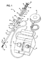
ここで、図、具体的には図1を参照すると、システム8は、概して、組織シーラントの複数成分等、複数の薬剤を身体内の標的部位に塗布するためのシステムの一実施形態を示す。組織シーラントは、例えば、トロンビン構成要素およびフィブリノゲン構成要素を含む線維素であり得る。適切なシーラントの1つは、本開示の譲受人によるFLOSEALシーラント製造会社であり得る。他のシーラントは、Baxter Healthcare Corporationから市販されているCOSEAL等のポリPEGベースの封止系、および液状形態、またはペーストもしくは粉末形態で提供される止血剤を含む。示されるシステムは、ガス支援塗布システムであり、これは、複数の薬剤アプリケータ装置10と、二重シリンジ物質アプリケータ12と、制御ユニット14と、加圧減菌ガスまたは空気供給源16とを含む。概して、アプリケータ装置10は、細長い剛性部分または送達シャフト18を含み、これは、送達シャフト18の遠位端22に位置する噴霧アプリケータまたはアセンブリ20等、アプリケータ先端を含む。一実施形態において、アプリケータ装置10は、小さい手術切開部を通して挿入され、標的部位に、またはそれに隣接して噴霧アプリケータ20を位置付ける。噴霧アプリケータ20が所望の位置にくると、組織シーラントの構成要素は、物質アプリケータ12から送達シャフト18を通して送られ、噴霧アプリケータ20を介して標的部位に塗布される。
(Detailed explanation)
Referring now to the drawings, and specifically to FIG. 1, system 8 generally illustrates one embodiment of a system for applying multiple agents, such as multiple components of a tissue sealant, to a target site within the body. The tissue sealant can be, for example, a fibrin that includes a thrombin component and a fibrinogen component. One suitable sealant may be a FLOSEAL sealant manufacturer by the assignee of the present disclosure. Other sealants include polyPEG-based sealing systems such as COSEAL commercially available from Baxter Healthcare Corporation, and hemostatic agents provided in liquid form, or paste or powder form. The system shown is a gas assisted application system, which includes a plurality of
図1に見られるように、制御ユニット14は、ガスを調節して、アプリケータ装置10に供給する。このような制御ユニットの1つは、本開示の譲受人により配布されたDuploSpray MIS(登録商標)である。制御ユニット14はガス供給源16に接続され、これは、一実施形態において、制御ユニット14に組み込まれ得る。制御ユニット14は、インターフェース部材34のポート64に接続されるライン62によるガス供給を含む。
As seen in FIG. 1, the
物質アプリケータ12は、1つ以上の薬剤をアプリケータ装置10に供給する。このような物質アプリケータは、概して、米国特許第6,884,232号および米国特許出願第11/331,243号に記載されており、双方とも本出願の譲受人に譲渡され、参考としてその全体が本明細書に援用される。物質アプリケータ12の実施形態は、実施例として示され、それを限定するものではないことを理解されたい。加えて、物質アプリケータは、単一または複数の貯蔵部等、代替構造を利用できる。
The substance applicator 12 supplies one or more medicaments to the
図2および3は、アプリケータ装置10の形成可能部分または部材24の一実施形態を示す。形成可能部分24は、剛性送達シャフト18と噴霧アプリケータ20との間に位置する。図3に見られるように、形成可能部分24は、形成可能部分を屈曲するように、通常は、手で力を加えることにより、所望の形状または構成に形成または成形され得る。形成可能部分24は、力が部分に再度加えられ、その部分を異なる構成に形成するまで、その構成を維持する。示される実施例において、形成可能部分24は、約90度の角度で屈曲される。形成可能部分24は、複数の角度を含む様々な角度で屈曲され、特定の手技または標的部位の位置により、様々なカスタム構成に成形され得ることを理解されたい。形成可能部分24の屈曲および形状保持は、以下で詳細に説明される。
2 and 3 illustrate one embodiment of the formable portion or
図1および4Aを参照すると、アプリケータ装置10は、剛性送達シャフト18と、インターフェース部材34と、噴霧アプリケータ20とを含む(図1)。剛性送達シャフト18は、生体適合性金属または生体適合性剛性重合体等、生体適合性剛性物質で作製される。一実施形態において、送達シャフトは、ステンレススチールで作製される。送達シャフト18は、近位端部分26と、遠位端部分22と、そこから延在する管腔28とを含む。図4Aを参照すると、近位端部分26は、インターフェース部材34の本体33の遠位端部分32に位置するポート30に受容され、取り付けられる。送達シャフト18は、また、管腔28を通って延在する、第1の流体導管36と、第2の流体導管38とを含む。一実施形態において、流体導管36、38は、管腔28を通って延在する個々の剛性導管またはパイプである。導管36、38は、例えば、ステンレススチール等の金属で作製され得る。図1に示す実施形態において、第1および第2の流体導管36、38のそれぞれの遠位端40、42は、送達シャフト18の遠位端22を越えて延在する。さらに、第2の流体導管38の遠位端42および第1の流体導管42の遠位端40は、ずらして配置される、例えば、遠位端42は、遠位端40より遠くに延在する。以下に詳細を説明するように、本遠位端のずらした配置は、噴霧アプリケータが詰まるのを防止することを支援する。
1 and 4A, the
インターフェース部材34の本体33は、第1のポート46と、第2のポート48とを有する近位端部分44も含む。第1のポート46は、第1の開口部50を含み、第2のポート48は、第2の開口部52を含む。開口部50、52は、物質アプリケータ12の分配先端部54および56を受容するように大きさが決定される。インターフェース部材34は、第1の流体チャネル58と、第2の流体チャネル60とをさらに含む。第1の流体チャネル58は、送達シャフト18の第1の流体導管36に動作可能に接続され、それと流体的に連絡する。第2の流体チャネル60は、送達シャフト18の第2の流体導管38に動作可能に接続され、それと流体的に連絡する。流体チャネル58、60は、それぞれ、物質アプリケータ12から受容した流体を第1および第2の流体導管36、38に伝送する。
The
図4Bを参照すると、本体33は、ライン62により供給されるガス流を送達シャフト18の管腔28に連絡するガス通路66を含む。図1に示すように、一実施形態において、制御ユニット14は、アプリケータ装置10に供給されるガス流を制御するための圧力制御68を含む。制御ユニット14は、ユーザがアプリケータ装置10へのガス流の開始および停止するためのフットスイッチ70等の、スイッチをさらに含む。加圧ゲージ72は、供給ライン62により供給されるガスの圧力の監視を可能にする。
Referring to FIG. 4B, the
図1および4Aに見られるように、物質アプリケータ12は、シリンジカプラ78により結合される、第1のシリンジ74と、第2のシリンジ76とを含む。第1のシリンジ74は、そこに配置される第1の構成要素を有する貯蔵部80を含む。貯蔵部80は、分配先端54と連絡する。ピストン84は、第1の貯蔵部80内に位置付けされ、プッシャー部材88に接続される近位端86を含む。
As seen in FIGS. 1 and 4A, the substance applicator 12 includes a
同様に、第2のシリンジ76は、そこに配置される第2の構成要素を有する貯蔵部90も含む。貯蔵部90は、分配先端56と流体的に連絡する。ピストン94は、第2の貯蔵部90に位置付けされる。ピストン94は、プッシャー部材88に接続される近位端96を含む。ピストン84、94の近位端86、96は、プッシャー部材88に動作可能に接続されるため、圧力がプッシャー部材88に加えられると、ピストン84および94は、一緒に移動して、等量の構成要素を貯蔵部から送達装置に前進する。
Similarly, the
分配先端54、56は、例えば、ルアー適合部によりインターフェース部材34のポート46、48に結合され得る。加えて、固定部材(図示せず)は、物質アプリケータ12をアプリケータ装置に固着できる。固着部材は、物質アプリケータをインターフェース部材に取り付けるストラップであり得る。
The dispensing
図5および6A〜6Cは、本開示の形成可能部分または部材24の一実施形態を示す。形成可能部分24は、製造過程中に送達シャフト18に完全に取り付けられ得るか、またはユーザにより送達アプリケータに任意に取り付けられるアダプタとして構成され得る。形成可能部分24は、様々な長さを有し得、一実施形態においては、約7.5cmの長さを有する。形成可能部分24は、送達シャフト18の遠位端22に取り付けられる近位端104と、噴霧アセンブリ20に取り付けられる遠位端106とを含む。
5 and 6A-6C illustrate one embodiment of the formable portion or
形成可能部分24は、細長い柔軟な管状要素114と、管状要素内に配置される展性挿入部122とを含む。可塑性管状要素114は、近位端116と、遠位端118とを有する。可塑性管状要素114は、塩化ポリビニルまたはポリウレタン、可塑性エラストマー(ペレタン)、および熱硬化エラストマー等の、適切で可塑性重合体物質で作製され得る。管状要素114は、展性挿入部122が配置される中央管腔120を含む。形成可能部分24が所望の構成に形成されると、展性挿入部122は、力が加えられ、形成可能部分122を異なる構成に再形成するまで、所望の構成に形成可能部分を保持する。一実施形態において、管状要素114および展性挿入部24は、形成可能部分が手で成形され得るように構成される。
展性挿入部122は、ステンレススチール、スチール、形状記憶合金等の医学的に許容される金属または合金で作製され得る。あるいは、展性挿入部122は、他の物質であり得る。あるいは、展性挿入部122は、エラストマー構築物内部に含まれる複数の剛性部分から作製され得るか、またはエラストマー構築物を通して互いに接続され得る。展性部分に加えられる曲げモーメントは、剛性部分を特定の角度で新しい状態に再度積み重ねる結果となる。エラストマー構築物は、システムに剛性さを与えるであろう。図示される実施形態において、展性挿入部122は、断面で正方形である金属ワイヤである。展性挿入部122は、多角形、楕円、円形、または不規則な形状等、他の断面形状も有することが可能である。展性挿入部122は、中央管腔120が形成された後に、管状要素114内に挿入され得る。あるいは、管状要素が展性挿入部122を越えて押し出される押出工程は、管状要素114を形成する。図5に見られるように、展性挿入部122の近位端123は、管状要素114の近位端116から延在し、展性挿入部122の遠位端125は、管状要素114の遠位端118を越えて延在する。以下に詳細に説明するように、近位端および遠位端123、125は、カプリング部材108および110に係合し、アライメントされる。一実施例において、展性セグメントは、他の方法で作動されてもよい。例えば、形状記憶合金を用いて、カッタの1つ等の温度源(または強力な光源)が局所的な温度の変更に、または先端の再構成に使用され得るが、あるいは、上流金属シャフト内に埋め込まれた電極およびカートリッジヒータが、挿入部の温度の変更に使用され得る。
The
図6Aおよび6Bに見られるように、管状要素114は、近位端116と遠位端118との間に延在する一対の管腔124および126も含む。管腔124および126は、同様に成形され得、展性挿入部122の反対側に位置し得る。図示される実施形態において、管腔124および126は、概して、円径を有する。管腔124、126は、多角形状または楕円形状等の、他の断面形状を有することができる。
As seen in FIGS. 6A and 6B, the
図6Bに示すように、管腔124は、第1の流体導管36からの流体と流体的に連絡し、それを受容する。管腔126は、第2の流体導管38からの流体と連絡し、それを受容する。図6Aおよび6Cに見られるように、管状要素114は、近位端116と遠位端118との間に延在する第2の一対の管腔128、130も含む。管腔128および130は、送達シャフト18の管腔28と流体的に連絡し、そこを通して加圧ガスを通過させる。管腔128,130も、展性挿入部122の反対側に位置し得る。図6Aに示される実施形態において、管腔128、130は、概して、半円の形状である断面を有する。管腔128、130は、円形または多角形等の、他の断面形状も有し得る。
As shown in FIG. 6B, the
図5、6Bおよび6Cに示すように、形成可能部分24は、管状要素114の近位端部分116に取り付けられるカプリング部材108を含む。カプリング部材108は、形成可能部分24を送達シャフト18に取り付けるように構成される。図5および7に示すように、カプリング部材108は、第1部分132と第2部分142とを有する円筒形状体133を含む。第1部分132は、空洞136を画定する内面134を含む。空洞136は、管状要素114の近位端部分116を受容する。近位端部分116は、例えば、接着剤結合、溶接、機械的ロック(スナップ式接合、ネジ、およびオーバーレイ等)、または摩擦嵌合/スエージングによって、カプリング部材108の表面134に取り付けられ得る。カプリング部材108は、また、図6Bおよび6Cに示すように、展性挿入部122の近位端部分123に係合する凹部140を形成する内壁138を含む。示される実施形態において、凹部140は、概して、展性挿入部122の一般的な外径と対応する正方形構成を有する。この係合は、安定性を提供し、カプリング部材を管状要素と適切にアライメントすることを支援する。図6B、6Cおよび7に見られるように、カプリング部材108の第2部分142は、ネジ山144を含み、これは、カプリング部材を送達シャフト18に取り付けるように、送達シャフト18の内壁に位置する対応するネジ山146と噛合される。
As shown in FIGS. 5, 6B and 6C, the
図6Bに見られるように、カプリング部材108の内壁138は、第1の延長部148と第2の延長部150とを含む。第1の延長部148は、流体チャネル152を含む。カプリング部材108が、送達シャフト18に結合すると、第1の延長部148がアライメントされ、第1の流体導管36と密閉して噛合されるため、流体チャネル152が第1の流体導管36と流体的に連絡する。さらに、チャネル152の開口部154がアライメントされ、管状要素114の管腔124と流体的に連絡する。同様に、第2の延長部150は、流体チャネル156を含む。第2の延長部150がアライメントされ、第2の流体導管38と密閉して噛合されるため、流体チャネル156が第1の流体導管38と流体的に連絡する。加えて、チャネル156の開口部158は、管状要素114の管腔126とアライメントされ、流体的に連絡するため、流体は、流体導管38からカプリング部材108を通って管腔126に流れ込むことができる。他の封止構造は、一度一緒になるとその部分が互いに封止されるような、ボルケーノ・バルブで持ち上げられた三角形の突起、および変形可能/エラストマー部分を含む場合がある。各流体から流体、またはガスからガスの接合点は、これらの特徴から利点を受ける場合がある。
As seen in FIG. 6B, the
図6Cを参照すると、カプリング部材108の内壁138は、そこを通る一対のガスチャネル160、162も含む。開口部160、162は、送達シャフト18の管腔28と流体的に連絡する。加えて、開口部160、162が位置付けられ、管状要素114の管腔128および130とアライメントされる。ガスは、送達シャフト18の管腔28からカプリング部材108を通って管状要素114の管腔128および130内に流れ込む。上述のように、カプリング部材108の内壁138は、展性挿入部122の端123に係合する凹部140を含むことができる。本係合は、壁138の開口部を管状要素114の管腔とアライメントし、このようなアライメントを保持することを支援する。
Referring to FIG. 6C, the
図5、6Bおよび6Cに見られるように、形成可能部材24は、管状要素114の遠位端118に取り付けられる第2のカプリング部材110も含む。カプリング部材110は、噴霧アセンブリ20を形成可能部分24に取り付けるように構成される。カプリング部材110は、概して、管状要素114の遠位端部分118を受容するための空洞を画定する内面166を含む、円筒体164を含む。カプリング部材110は、例えば、接着剤結合または溶接によって、管状要素114に取り付けられ得る。
As seen in FIGS. 5, 6B and 6C, the
図5および6Bを参照すると、カプリング部材110は、そこから延在する第1の流体導管170と、第2の流体導管172とを有する内壁168も含む。第1および第2の流体導管170および172は、カプリング部材110の遠位端部分174を越えて延在する。一実施形態において、第1の流体導管170は、第2の流体導管172より遠くに延在する。別の実施形態において、カプリング部材110の遠位端部分174は、送達シャフト18の遠位端部分22を模倣し、流体導管170、172は、流体導管36および38が送達シャフト18から延在するのと同じ割合で、カプリング部材110の遠位端部分から延在する。あるいは、導管170、172は、カプリング部材110の遠位端174から同じ距離で延在する。
With reference to FIGS. 5 and 6B, the
カプリング部材110は、管状要素114に取り付けられるため、流体導管170の開口部175は、管腔124とアライメントされ、流体的に連絡し、流体導管172の開口部176は、管腔126とアライメントされ、流体的に連絡する。内壁168は、図6Cに示すように、管腔128、130と流体的に連絡するガスチャネル178、180を画定する。さらに、カプリング部材108と同様に、内壁168は、展性挿入部122の遠位端125に係合する凹部171を含む。
Because the
図6Bおよび6Cに見られるように、カプリング部材110の内面167は、噴霧アプリケータ20の近位端186上に位置する対応するネジ山184と噛合するネジ山182を含む。噴霧アプリケータ20は、一実施形態において、カプリング部材110に噴霧アプリケータ20を装着および脱着することにより、形成可能部材24に解放可能に取り付けられる。解放可能に取り付け可能な噴霧アプリケータを利用する利点の1つは、噴霧アプリケータが操作中に詰まった場合、噴霧アプリケータは、形成可能部材から外され、新しい噴霧アプリケータに交換できることである。
As can be seen in FIGS. 6B and 6C, the
図5、6Bおよび6Cに示すように、一実施形態における噴霧アプリケータ20は、概して、標的部位に物質を塗布するための、または噴霧するための混合空洞190および開口部192を画定する円筒体188を含む。噴霧器の他の例は、全て内部混合を備える圧力旋回空圧噴霧器、衝突噴流空圧(impinging−jt−pneumatic)噴霧器、直交流空圧噴霧器、および外部混合のために構成される噴霧器を含む。噴霧アプリケータ20がカプリング部材110に接続されると、第1の流体導管170および第2の流体導管172は、混合空洞190内の流体的な連絡に配置される。図6Bに見られるように、流体導管170、172を通って前進する流体は、流体が噴霧アパーチャ192を通って放出される前に混合される、混合空洞190に進入する。第1の導管170および第2の導管172の異なる長さは、噴霧アプリケータが詰まるのを防止することを支援する。好ましくは、触媒構成要素(例えば、トロンビン構成要素)は、長い側にあり、その導入は、さらに下流であり、概して、活性構成要素管腔に達するように上流に移動しないため、凝固の可能性はほとんどない。図6Cに示すように、混合空洞190は、カプリング部材110の開口部178、180を通過するガス流も受容する。ガス流は、流体の混合およびアパーチャ192から混合物を放出することを支援する。
As shown in FIGS. 5, 6B and 6C, the
操作中、形成可能部分24は、カプリング部材108を送達シャフト18の遠位端22に装着することによって、送達シャフト18に取り付けられる。噴霧アプリケータ20は、それから、噴霧アプリケータをカプリング部材110に装着することによって、形成可能部分24に取り付けられる。あるいは、形成可能部分24、噴霧アプリケータ20、および送達シャフト18は、製造中に、予め組み立てられる。ガス供給ライン62は、ポート64に取り付けられ、物質アプリケータ12の分配先端54、58は、インターフェース部材34のポート46、48内に挿入される。あるいは、固着部材は、利用される場合、同物を送達装置に固定するように、物質アプリケータ12に取り付けられる。
During operation, the
形成可能部分24は、それから、通常は、所望の構成に手で屈曲、または変形される。上述のように、展性挿入部122は、形成可能部分を異なる構成に変更するように、十分な力が加えられるまで、形成可能部分24をその構成に維持する。
The
噴霧アプリケータ20、形成可能部分24、および送達シャフト18は、それから、患者の身体内に挿入される。噴霧アプリケータ20は、対象領域に前進する。適切に位置付けられると、供給ライン62およびインターフェース部材34のガス通路66を通ってガス流を供給するように、制御ユニット14のスイッチ70を作動させる。ガス流は、送達シャフト18の管腔28、および管状要素114の管腔128、130を通過して、噴霧アプリケータ20入る。一実施形態において、ユーザは、分配先端54、56の方向にピストン84、94を移動するように、カプラ78のプッシャ部材88に手動力を加える。貯蔵部80、90内に保存される物質は、分配先端54、56を通って流体導管36、38内に前進する。手動力の連続した塗布は、管状要素114の管腔124、126を通ってカプリング部材110の流体導管170、172内に前進する。物質は、それから、導管170、172から外へ流れ出て、噴霧アプリケータ20の混合空洞190内に流れ込む。物質は、混合空洞190で混合する。あるいは、ガスは、物質と混合される。混合物およびガスは、物質を標的部位に塗布するように、噴霧アプリケータ20の開口部192の外へ噴霧される。
The
形成可能部分または部材24は、また、上記の参考として援用される、米国特許第6,884,232号に記載されるもの等、ガス支援されない機械式アプリケータシステムで使用され得る。図8は、ガス支援されない噴霧アプリケータの一例を示す。ここで、機械式噴霧アプリケータ200は、形成可能部分24のカプリング部材110に取り付けられる。噴霧アプリケータ200は、第1の流体チャネル204および第2の流体チャネル206と連絡する混合チャンバ202を含む。第1の可撓性混合部材208aおよび第2の可撓性混合部材208bは、混合チャンバ202内、第1および第2の流体チャネル204、206に隣接して位置付けられる。混合部材208aおよび208bは、混合チャンバ202内に乱流を形成することによって、2つの物質構成要素の衝突混合を引き起こすことを支援する。操作中、個々の構成要素は、送達シャフト18の流体導管36、38、形成可能部分24の管腔124、126、ならびにカプリング部材110の流体導管170および172を通って流体チャネル204、206に前進する。混合チャンバ202において、構成要素は、混合部材208aおよび208bを係合する。混合部材208aおよび208bは、流体の流れを乱し、構成要素を混合チャンバ内で混合させる、狭いチャネルを提供する。
Formable part or
噴霧調節器210は、噴霧アパーチャ212に隣接する混合チャンバ内に位置付けられる。噴霧調節器は、混合チャンバ内に位置する物質が混合されることを確実にし、物質噴霧を形成することを支援するように混合チャンバ内のインピーダンスを提供する。本開示は、本明細書で説明する噴霧アプリケータに限定されない。
A
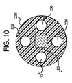
図9および10は、本開示の形成可能部分の別の実施形態を示す。形成可能部分24と同様に、形成可能部分24aは、近位カプリング部材220と、遠位カプリング部材222とを含む。近位カプリング部材220は、形成可能部材24aを送達シャフト18の遠位端22に取り付ける。本明細書で説明されるあらゆる噴霧アプリケータが、遠位カプリング部材222に取り付けられ得る。
9 and 10 illustrate another embodiment of the formable portion of the present disclosure. Similar to
形成可能部分24aは、細長い管状要素226と、管状要素を通って延在する展性挿入部228とを含む。管状要素226は、展性挿入部228の反対側に一対の管腔232、234も含む。管腔232、234は、流体導管36、38からの流体と連絡し、それを受容する。管状要素226は、展性挿入部の反対側に第2の一対の管腔236、238も含む。管腔236、238は、概して、円形の断面径を有し、そこからガスを受容するように管腔28と連絡する。カプリング部材220、222は、概して、上述のカプリング部材108、110と同様であり、流体およびガスの通過のために、開口部と、流体チャネルとを有する。
ここで、図11および12を参照すると、本開示の形成可能部分のさらなる実施形態が示される。本実施形態において、形成可能部材24bは、そこを通る流体の通過のための単一管腔を含む。形成可能部分24bは、近位カプリング部材と、遠位カプリング部材(図示せず)とを含む。近位カプリング部材は、形成可能部分24bを送達シャフト18に結合する。さらに、噴霧アプリケータは、遠位カプリング部材に結合され得る。形成可能部分24bは、そこを通る管腔256を有する可撓性管状要素254を含む。管腔256は、送達シャフト18からの流体と流体的に連絡し、それを受容する。展性挿入部258は、可撓性管状要素254を介して形成される管腔260に配置される。展性挿入部は、管状要素が形成された後に管腔に配置され得るか、または管状要素は挿入部を越えて押し出され得る。前の実施形態と同様、形成可能部分24bは、所望の構成に成形され得、展性挿入部258は、形成可能部分が再成形されるまで、その構成に形成可能部分24bを保持することを支援する。
Referring now to FIGS. 11 and 12, a further embodiment of the formable part of the present disclosure is shown. In this embodiment, the formable member 24b includes a single lumen for the passage of fluid therethrough. Formable portion 24b includes a proximal coupling member and a distal coupling member (not shown). The proximal coupling member couples the formable portion 24b to the
形成可能部分24bは、複数成分を送達するように構成される送達シャフトを用いて使用され得る。形成可能部分24bは、単一物質を送達する単一の送達シャフトを用いて使用され得る。複数成分システムを用いて使用される時、物質は、管状要素254の管腔256で混合され得る。混合物は、管腔を通って、混合物を塗布する噴霧アセンブリに前進する。
Formable portion 24b can be used with a delivery shaft configured to deliver multiple components. Formable portion 24b can be used with a single delivery shaft that delivers a single substance. When used with a multi-component system, the material can be mixed in the
図13〜17を参照すると、形成可能部材または展性チューブ、およびアプリケータの別の主要な実施形態は、展性チューブアセンブリ250により図示される。展性チューブアセンブリ250は、ルアーアンカ280に取り付けられる、第3の展性チューブ実施形態224を含む。展性チューブ224は、上述の任意の用途で、あるいは使用され得る。一構成において、ルアーアンカ280は、上述のFLOSEAL剤等、本明細書に記載される任意の創傷シーラント剤を保有するシリンジに取り付けられる。
With reference to FIGS. 13-17, another major embodiment of the formable member or malleable tube and applicator is illustrated by the
ルアーアンカ280は、ABS(Terlux2802HDおよびその他)、HDPE、ポリプロピレン、ナイロン、および他のエンジニアリングプラスチックス等の、適切な医療グレードのプラスチックから鋳型される。ルアーアンカ280は、雌ルアー近位端284を有する中空体282を含む。雌ルアー近端は、シリンジアプリケータ等のアプリケータの雄ルアーに接続される。本体282の遠位端286は、平坦面と、展性チューブ224をぴったりと受容するサイズの直径とを有する。
The
フランジ290aおよび290bは、互いから180度離れ、かつ本体282から外方向に延在する。フランジ290aおよび290bは、各々、縫合孔またはディボット292a〜292cを画定する。縫合孔またはディボット292a〜292cは、フランジ290aおよび290b、よって展性チューブアセンブリ250が、例えば、患者の手術部位に配置される手術用ドレープに縫い付けられる、または固定されることを可能にする。ドレープは、手術の進入部位の周りに配置される。孔の端は、したがって、進入部位に近接する。フランジ290aおよび290bは、展性チューブアセンブリ250が手術進入部位の近くに、しかしそこを除けて固定されるように、端の近くに固着される。創傷シーラントは、手技中、異なる時間に、通常は手技の終わりに、そして患者が内出血をしている場合は、おそらく、手技中1回または数回、必要とされる場合がある。したがって、展性チューブアセンブリ250を利用可能にしておき、必要な時に使用するために固定された位置にあり、不要な時には、除けられていることが望まれる。以下に説明するように、展性チューブ224は、シーラント剤が必要とされる時まで除けて固定して屈曲され得、その時、チューブはシーラント塗布位置に固定して屈曲され得る。
ルアーアンカ280は、チューブクランプ294も含む。チューブクランプ294は、ルアーアンカが、他の内視鏡アプリケータのシャフト、IV、または灌注管等の管状構成を保有すること、またはそれに保有されることを可能にする。チューブクランプ294は、軟質または硬質チューブの周りにスナップ式に接合し、約0.100インチ〜約0.300インチ等、通常の外径チューブのサイズである。
The
図14Bは、展性チューブ224が、どのようにルアーアンカ280内に固定されるかの一実施形態を示す。アンカ280の本体282は、展性チューブ224をぴったりと受容する大きさである大径口296を画定する。図示するように、大径口296は、本体282の約半分まで、さもなければアンカ280内にチューブ224を固着するように使用される取り付け方法に適する距離まで延在する。一実施形態において、チューブ224は、アンカ280内部に溶媒結合される。大径口296は、展性チューブ224の内径と約同じ径の大きさの小さい径口298に移行され、シリンジからチューブ224へのシーラント物質の円滑な移行を提供する。
FIG. 14B illustrates one embodiment of how
図14Bは、また、展性チューブ224の遠位端230の断面図を示す。図示するように、伝導性または金属ワイヤ240aおよび240bは、重合体チューブ244の端部の手前で終わる。チューブ244は、例えば、高周波溶接で、溶接領域242の差し込み距離で封止される。例えば、金属ワイヤ240aおよび240bは、遠位端230の先端から約0.130インチで終わることができる。差し込み溶接ラインまたは領域242は、それから、遠位端230の先端から約0.125インチ内に配置されることができる。創傷部位で遠位端230が患者に接触するため、遠位端230で金属ワイヤ240aおよび240bを用いずに延在する軟質プラスチックの部分を提供することが望まれる。軟質な重合体先端は、金属ワイヤ240aおよび240bを患者に直接接触させる、または遠位端230の先端に近づけるのとは対照に、患者にとってより快適である。純プラスチック先端230は、図14Bに示すように丸くされるため、患者は鋭利な縁と接触しない。チューブ244用の物質は、約60以上のショア剛性を有することができ、実装の1つにおいて、80のショア剛性を有する。
FIG. 14B also shows a cross-sectional view of the
図15Aおよび15Bは、展性チューブ224の2つの補強ワイヤ実施形態を示す。一実施形態において、チューブ244は、ペレタン物質で作製される。DEHP未含有PVC、PBAX等の他の物質が、チューブ224に使用されてもよいが、ペレタンは、透明かつ低色で、オイルおよび燃料への良好な耐性、良好な耐摩擦性、良好な耐寒性、菌類および微生物への耐性、押出し能力を含む良好な加工性、良好な引裂および穿刺耐性を示す。チューブ224は、約0.150インチ〜約0.200インチの外径、壁厚は、約0.010インチ〜約0.050インチを有することができる。チューブ224の長さは、ルアーアンカ280の縁から約15cmであり得る。
FIGS. 15A and 15B show two reinforcing wire embodiments of
金属ワイヤ240aおよび240bは、一実施形態において、例えば、約0.020インチ〜約0.030インチの直径を有し得る、ステンレススチール304等、ステンレススチールで作製される。ステンレススチールワイヤは、一実施形態において、極軟から四半分軟タイプである。幅広ゲージワイヤは、極軟ワイヤで使用されてもよく、一方、薄厚ワイヤは、四半分軟ワイヤで使用されてもよい。ワイヤは、単一でまたは集合的に十分に硬いため、展性チューブ224は、屈曲されると、別の位置に屈曲されるまでその屈曲位置を保持する。
図示するように、図15Aの展性チューブ224は、2つの補強ワイヤ240aおよび240bを含み、一方、図15Bの展性チューブ224は3つの補強ワイヤ240a〜240cを含む。両場合において、チューブ224は、等方性質を示す、すなわち、チューブ224は、両ワイヤ240aおよび240bを通って延在する平面で容易に屈曲しないが、両ワイヤ240aおよび240bを通って延在する平面に垂直な平面(または方向)で、容易に屈曲する。したがって、図15Aの展性チューブ224は、ワイヤ240aおよび240bを通る平面に垂直な平面で容易に屈曲するが、図13、14Aおよび14Bに関して以下に示すように、平面を通して容易に屈曲しない。
As shown, the
図15Bのチューブ224は、それぞれ、12時、3時、および6時で離れる3つのワイヤ240a、240c、および240bを有する。ワイヤは、あるいは、120度で互いから近等に離される。図15Bにおいて、チューブ224は、ワイヤ240aおよび240bを通る平面に垂直な平面で、単一方向でのみ屈曲できる。チューブ224は、ワイヤ240aおよび240bの中央を通るラインに垂直である左(9時の方向)に屈曲できるが、ワイヤ240aおよび240cならびにワイヤ240bおよび240cのアライメントにより作製される反力ベクタのため、ワイヤ240aおよび240cの中央を通るラインに垂直である右(3時の方向)には容易に屈曲できない。
The
補強平面は、医師または技術者に、チューブ224操作の安定性を提供し、それによって、望ましい平面または方向に屈曲するシーラント塗布装置を医師に提供し、またチューブ224がある位置に移動した後に望ましい平面または方向への剛性を提供する。図13、14Aおよび14Bは、ルアーアンカ280のフリンジ290aおよび290bに関して、補強ワイヤ240aおよび240bの望ましい配向の1つを示す。本配向において、ワイヤ240aと240bの中央ラインの間を通過する仮想ライン(例えば、図13に示すx軸)は、同じでなければ、フランジ290aおよび290bの中央を通る平面に平行する平面に存在する。図13に見られるように、フランジ290aおよび290bの縫合孔292a〜292cが、例えば、手術用ドレープ等の外科手術のために固着される時、展性チューブ224は、z軸の周りでの屈折を拘束するが、x軸の周りでは屈折可能である。医師または技術者は、したがって、ドレープの上で離れた展性チューブ224を屈折でき、チューブは、シーラントの塗布が不要の時、引戻し位置で保持される。患者が出血している場合、医師または技術者は、x軸の周りの複数の位置のドレープおよび患者に対して下に屈曲することにより、チューブをすぐに創傷部位の所望の位置に向けることができる。
The stiffening plane provides the physician or technician with the stability of the
z軸の周りのチューブ224の屈曲の剛性または拘束の主な利点の1つは、患者の内部に挿入された時、チューブが医師に提供する横方向の締め付け能力である。すなわち、医師は、患者の組織および/または臓器を塗布部位から除けて操作し、保持するようにチューブ224を使用できる。チューブ224は、本質的に、医師によって除けて移動されると、組織または臓器が移動され、それらの自然な位置に戻るのを拘束する。チューブ224は、複数方向への屈曲を達成するように回転され得、必要な可撓性を提供する。図15Bのチューブ224は、一方向に展性を維持する一方、より多くの方向に剛性を提供し、これは、特定の医師または特定の手技に望ましい場合がある。
One of the main advantages of bending or constraining the
図16Aおよび16Bは、図14Bと関連して先に示され議論された、差し込み円形部242での溶接の作製、および遠位先端230の形成方法の1つを示す。図16Aにおいて、ワイヤ240aおよび240bの周りに重合体チューブ244を、例えば、16mlの所望の長さに押し出した後、重合体チューブ244とワイヤ240aおよび240bとを含む展性チューブ224は、遠位先端部230で切断される。次に、重合体チューブ244は、座屈または図16Bのように座屈するように、ワイヤ240aおよび240bに沿って内方向に押されるため、上述のように、所望の長さのワイヤ240aおよび240bが、例えば、0.030インチだけクリンプされる(縁を曲げられる)または切断されるように曝される。そのワイヤ240aおよび240bの長さは、それから、図16Aに示すように、ワイヤの残部からクリンプされる。
FIGS. 16A and 16B illustrate one of the methods of making a weld at the
図16Bは、重合体チューブ244が、それから、その非圧縮状態に巻き出させるため、遠位先端230は、ワイヤ240aおよび240bの端を越えて所望の長さに延在することを示す。重合体チューブ244は、それから、差し込み円形部242で溶接されて、ワイヤのクリンプ端の周りでチューブを封止する。遠位先端230の丸い縁は、軟化点を越えて物質を加熱し、治具で成形されることにより形成されるため、先端230との接触時の患者の快適さは増大する。
FIG. 16B shows that the
図17Aは、展性チューブ224の遠位端または先端230を作製するための代替実施形態の1つを示す。ここで、端キャップ270は、切断端272aまたは272bに装着され(図15Aおよび15Bを参照のこと)、例えば、継目274および/または継目276で展性チューブ224に高周波溶接される。キャップ270は、例えば、ペレタン等、本明細書で特定される任意の物質で作製され得る。あるいは、キャップ270は、軟質ゴム、熱可塑性および/または例えば、ペレタンチューブ244に溶接される、極めて軟質な物質で作製される。キャップ270は、一実施形態において、図14Bに示す延在されるプラスチック先端の表面と実質的に同様の表面を各端に有する。すなわち、最遠位先端230で、キャップ270は、非応力状態で、実質的に円形である端面を有す(形状は、実際には、わずかに楕円であるか、さもなければワイヤによる押し出しにより歪められ得る)。キャップ270のインターフェースおよびチューブ244の端で、キャップ270は、例えば、それぞれ、図15Aおよび15Bで示される切口面または端272aおよび272b等の、チューブ244の端面と少なくとも実質的に同様の端面を有する。
FIG. 17A shows one alternative embodiment for making the distal end or tip 230 of
図17Bは、展性チューブ224の端に渡って配置されてもよい、代替キャップ290を示す。代替キャップは、キャップ270の遠位端と同様の遠位端230を含む(図17a)。また、図15Aを参照すると、キャップ290は、図15aで最も良く示される、チューブ224の端の挿入を可能にするように成形される空洞292も形成する。具体的には、キャップ290は、遠位端部分298と共に空洞292を形成する、内側環状フランジ294および外側環状フランジ296を含む。空洞292は、触媒結合等による、任意の適切な方法での取り付けを提供する方法で、チューブ224の遠位端を受容するように寸法される。
FIG. 17B shows an
内側フランジ224は、空洞292に対向ポケット300を形成するように構成される。ポケット300は、ワイヤ240aおよび240b、ならびにワイヤを包囲する管244の重合体を受容し、チューブ224の内側通路の長さに沿って対向半円凹部304を形成するように構成される。
外周で丸くされているが、平坦または平滑な垂直面を有する遠位先端230を有するキャップ270および290を示す。キャップ270は、管状出口通路を形成し、キャップ290は、漏斗型出口通路を形成する。代替実施形態において、遠位先端230は、雄ルアー先端(図示せず)に円錐形に形成され、これは、それから、第2のアセンブリ250の近位雌ルアー先端が、第1のアセンブリ250の遠位雄ルアー先端と接続されるルアーを形成することを可能にする。本方法において、医師は、所望のより長い長さの展性アプリケータを作製できる。第2またはより遠位のアセンブリ250のルアーアンカは、このような構造が必要な可能性がなく、また手技を妨害する場合があるため、フランジ290a、290bおよびチューブホルダ294を用いずに作製され得ることが考えられる。別の器具250の補強ワイヤ240aおよび240bをアライメントする、舌状および溝状特性等の、噛合器具を用いて雌ルアーおよび雌ルアー先端を供給することも考えられる。さもなければ、医師または技術者は、視覚によりワイヤをアライメントできる。
本明細書に説明される本好適な実施形態への様々な変更および修正は、当該分野の当事者には明らかであることを理解されたい。このような変更および修正は、本主題の精神および範囲から逸脱することなく、かつその意図する利点を低減することなくなされ得る。したがって、このような変更および修正は、付属の特許請求の範囲によって網羅されることを意図する。 It should be understood that various changes and modifications to the presently preferred embodiments described herein will be apparent to those skilled in the art. Such changes and modifications can be made without departing from the spirit and scope of the present subject matter and without diminishing its intended advantages. Accordingly, such changes and modifications are intended to be covered by the appended claims.
Claims (27)
自身を通る流体の通過のために構成される剛性部分であって、該剛性部分は近位端部分と遠位端部分とを有し、該近位端部分は少なくとも1つの流体貯蔵部との連絡のために構成される、剛性部分と、
該剛性部分の該遠位端部分に取り付けられる形成可能部分であって、該形成可能部分は所望の構成に成形されるように構成され、該形成可能部分は少なくとも第1の管腔と第2の管腔とを含み、該第1の管腔は該剛性部分から流体を受容するように構成される、形成可能部分と、
該第2の管腔内に配置される展性部材であって、該展性部材は、所望の構成で該形成可能部分を保持することを支援するように構成される、展性部材と
を備える、装置。 An applicator device for applying at least one drug to a target site,
A rigid portion configured for passage of fluid therethrough, the rigid portion having a proximal end portion and a distal end portion, the proximal end portion being at least one fluid reservoir; A rigid portion configured for communication; and
A formable portion attached to the distal end portion of the rigid portion, the formable portion configured to be molded into a desired configuration, the formable portion comprising at least a first lumen and a second A first formable lumen configured to receive fluid from the rigid portion; and
A malleable member disposed within the second lumen, wherein the malleable member is configured to assist in holding the formable portion in a desired configuration; A device comprising.
近位端と、遠位端と、そこを通って延在する管腔とを有する、細長い剛体と、
該管腔内に延在する、第1の流体送達導管および第2の流体送達導管であって、該第1の流体送達導管は、第1の流体貯蔵部と流体的に連絡するように構成され、該第2の流体送達導管は、第2の流体貯蔵部と連絡するように構成される、流体送達導管と、
近位端と、遠位端と、そこを通って延在する第1および第2の流体チャネルとを有する、形成可能部材であって、該形成可能部材の該近位端は、該細長い本体の該遠位端に動作可能に接続され、該第1の流体チャネルは、該第1の流体送達導管に連絡し、該第2の流体チャネルは、該第2の流体送達導管に連絡し、該形成可能部材は、第1の構成から第2の構成に屈曲するように構成される、形成可能部材と、
該形成可能部材の管腔を通って延在する展性挿入部であって、該展性挿入部は、該第2の構成で該形成可能部材を保持することを支援するように構成される、展性挿入部と
を備える、装置。 A laparoscopic device for mixing and applying a multi-component drug to a target site,
An elongate rigid body having a proximal end, a distal end, and a lumen extending therethrough;
A first fluid delivery conduit and a second fluid delivery conduit extending into the lumen, wherein the first fluid delivery conduit is configured to be in fluid communication with a first fluid reservoir. And wherein the second fluid delivery conduit is configured to communicate with the second fluid reservoir;
A formable member having a proximal end, a distal end, and first and second fluid channels extending therethrough, the proximal end of the formable member comprising the elongate body Operably connected to the distal end of the first fluid channel, the first fluid channel communicates with the first fluid delivery conduit, the second fluid channel communicates with the second fluid delivery conduit, The formable member configured to bend from a first configuration to a second configuration; and
A malleable insert extending through the lumen of the formable member, the malleable insert configured to assist in holding the formable member in the second configuration And a malleable insertion portion.
形成可能管であって、近位端と、遠位端と、該管を通して該薬剤を流すための管腔とを有する、形成可能管と、
該管内に配置され、それに沿って延在する、展性部材であって、該形成可能管がある位置に誘導されると、該展性部材は、該位置で該形成可能管を保持するように構成される、展性部材と
を備える、展性チューブ。 A malleable tube for applying a drug,
A formable tube having a proximal end, a distal end, and a lumen for flowing the drug through the tube;
A malleable member disposed within and extending along the tube, wherein when the formable tube is guided to a location, the malleable member holds the formable tube at the location A malleable tube comprising the malleable member.
自身を通る物質およびガスの通過のために構成される、剛性部分であって、該剛性部分は、近位端部分と、遠位端部分とを有する、剛性部分と、
該剛性部分の該近位端部分と流体的に連絡する、物質アプリケータと、
該剛性部分の該遠位端部分に取り付けられる、形成可能部分であって、該形成可能部分は、所望の構成に形成され、該所望の構成を保持するように構成され、該形成可能部分は、該剛性部分から流体およびガスを受容するように構成される、形成可能部分と、
該形成可能部分の遠位端に取り付けられる、アプリケータ先端であって、該アプリケータ先端は、該形成可能部分から流体およびガスを受容し、該流体を標的部位に塗布するように構成される、アプリケータ先端と
を含む、システム。 A system for applying one or more drugs to a target site in the body,
A rigid portion configured for the passage of substances and gases therethrough, the rigid portion having a proximal end portion and a distal end portion;
A substance applicator in fluid communication with the proximal end portion of the rigid portion;
A formable portion attached to the distal end portion of the rigid portion, wherein the formable portion is formed in a desired configuration and configured to retain the desired configuration, the formable portion being A formable portion configured to receive fluid and gas from the rigid portion;
An applicator tip attached to a distal end of the formable portion, the applicator tip configured to receive fluid and gas from the formable portion and apply the fluid to a target site A system including an applicator tip.
Applications Claiming Priority (2)
| Application Number | Priority Date | Filing Date | Title |
|---|---|---|---|
| US2392608P | 2008-01-28 | 2008-01-28 | |
| PCT/US2009/032114 WO2009097271A1 (en) | 2008-01-28 | 2009-01-27 | Sealant application with malleable section |
Publications (2)
| Publication Number | Publication Date |
|---|---|
| JP2011510710A true JP2011510710A (en) | 2011-04-07 |
| JP2011510710A5 JP2011510710A5 (en) | 2013-03-14 |
Family
ID=40600110
Family Applications (1)
| Application Number | Title | Priority Date | Filing Date |
|---|---|---|---|
| JP2010544473A Pending JP2011510710A (en) | 2008-01-28 | 2009-01-27 | Sealant applicator with malleable part |
Country Status (5)
| Country | Link |
|---|---|
| US (1) | US9622731B2 (en) |
| EP (1) | EP2247243B1 (en) |
| JP (1) | JP2011510710A (en) |
| ES (1) | ES2738049T3 (en) |
| WO (1) | WO2009097271A1 (en) |
Families Citing this family (19)
| Publication number | Priority date | Publication date | Assignee | Title |
|---|---|---|---|---|
| US9681860B2 (en) * | 2008-10-24 | 2017-06-20 | Dennis L Steffen | Halo tip spray head atomizer delivery manifold device |
| CA2795261C (en) * | 2010-04-05 | 2020-08-25 | Neomend, Inc. | Method and apparatus for wound sealant application |
| CH703974A1 (en) * | 2010-10-15 | 2012-04-30 | Medmix Systems Ag | Medical spray head with pressure gas support. |
| JPWO2012124595A1 (en) * | 2011-03-17 | 2014-07-24 | テルモ株式会社 | Application tool and application method |
| US10441959B2 (en) | 2011-10-28 | 2019-10-15 | Medtronic Xomed, Inc. | Multi-orifice spray head |
| US9486190B2 (en) | 2011-10-28 | 2016-11-08 | Medtronic Xomed, Inc. | Spray delivery system |
| US8974436B2 (en) | 2011-10-28 | 2015-03-10 | Medtronic Xomed, Inc. | Multi-sectioned cannula with multiple lumens |
| US20140031788A1 (en) | 2012-07-24 | 2014-01-30 | An-Min Jason Sung | Rigid reinforcing exoskeletal sleeve for delivery of flowable biocompatible materials |
| WO2015004709A1 (en) * | 2013-07-08 | 2015-01-15 | テルモ株式会社 | Application tool |
| WO2015153828A1 (en) | 2014-04-04 | 2015-10-08 | Hyperbranch Medical Technology, Inc. | Extended tip spray applicator for two-component surgical selant, and methods of use thereof |
| EP3197372B1 (en) * | 2014-09-22 | 2023-03-15 | Arsenal Medical, Inc. | Devices and systems for filling body cavities |
| CN108309795A (en) * | 2018-01-31 | 2018-07-24 | 广州迈普再生医学科技有限公司 | A kind of dual-purpose duplex mixing syringe connector and duplex mixing syringe |
| CN108339194B (en) * | 2018-04-03 | 2023-12-26 | 广州迈普再生医学科技股份有限公司 | Bendable sheath tube, injector nozzle and application thereof |
| WO2019052510A1 (en) * | 2017-09-18 | 2019-03-21 | 广州迈普再生医学科技股份有限公司 | Connector for double mixing syringe, long nozzle for double mixing syringe and double mixing syringe |
| CN108498905A (en) * | 2018-04-03 | 2018-09-07 | 广州迈普再生医学科技股份有限公司 | Hysteroscope type nozzle and hysteroscope type duplex mixing syringe for duplex mixing syringe |
| US11352247B2 (en) * | 2018-08-24 | 2022-06-07 | Rooftop Research, Llc | Manifold and fluid dispensing systems |
| WO2022024043A1 (en) * | 2020-07-31 | 2022-02-03 | Ethicon, Inc. | Dual syringe cartridge and housing |
| CN114404644A (en) * | 2022-01-20 | 2022-04-29 | 深圳兰度生物材料有限公司 | Medical adhesive and preparation method thereof |
| US20230309978A1 (en) * | 2022-03-31 | 2023-10-05 | Ethicon, Inc. | Sealant applicators having mixing and spraying assemblies with malleable sections and spray tips having reduced dimensions |
Citations (2)
| Publication number | Priority date | Publication date | Assignee | Title |
|---|---|---|---|---|
| JP2006500100A (en) * | 2002-09-20 | 2006-01-05 | ジェンザイム・コーポレーション | Multi-pressure biocompatible drug delivery device and method |
| JP2006255401A (en) * | 2005-02-14 | 2006-09-28 | Biosense Webster Inc | Steerable catheter with in-plane deflection |
Family Cites Families (59)
| Publication number | Priority date | Publication date | Assignee | Title |
|---|---|---|---|---|
| US3169528A (en) | 1963-05-24 | 1965-02-16 | Iii Francis S Knox | Coronary sinus sucker |
| US3612038A (en) | 1969-02-03 | 1971-10-12 | Becton Dickinson Co | Preformable catheter package assembly and method of preforming |
| US3996939A (en) | 1975-07-22 | 1976-12-14 | National Catheter Corporation | Intubation stylets |
| US4596564A (en) | 1981-01-29 | 1986-06-24 | Pmt, Inc. | Medical appliance |
| US4430083A (en) | 1981-03-06 | 1984-02-07 | American Hospital Supply Corporation | Infusion catheter |
| AT379311B (en) | 1984-03-29 | 1985-12-27 | Immuno Ag | DEVICE FOR APPLICATING A TISSUE ADHESIVE |
| US4834709A (en) | 1986-03-26 | 1989-05-30 | Sherwood Medical Company | Preformable catheter |
| JPS6458263A (en) | 1987-08-28 | 1989-03-06 | Terumo Corp | Intravascular introducing catheter |
| US4976688A (en) | 1989-02-03 | 1990-12-11 | Rosenblum Jeffrey L | Position-adjustable thoracic catheter |
| US5004128A (en) | 1989-02-07 | 1991-04-02 | Thomas Richichi | Flexi-nozzle |
| US5322510A (en) | 1989-11-21 | 1994-06-21 | Andreas Lindner | Injection apparatus |
| US5221255A (en) | 1990-01-10 | 1993-06-22 | Mahurkar Sakharam D | Reinforced multiple lumen catheter |
| US5180376A (en) | 1990-05-01 | 1993-01-19 | Cathco, Inc. | Non-buckling thin-walled sheath for the percutaneous insertion of intraluminal catheters |
| US5190520A (en) | 1990-10-10 | 1993-03-02 | Strato Medical Corporation | Reinforced multiple lumen catheter |
| US5304131A (en) | 1991-07-15 | 1994-04-19 | Paskar Larry D | Catheter |
| US5234406A (en) * | 1992-04-06 | 1993-08-10 | The Regents Of The University Of California | Method and system for continuous spinal delivery of anesthetics |
| US5620447A (en) | 1993-01-29 | 1997-04-15 | Smith & Nephew Dyonics Inc. | Surgical instrument |
| AT400304B (en) * | 1994-02-28 | 1995-12-27 | Immuno Ag | DEVICE FOR APPLICATING A MULTI-COMPONENT TISSUE ADHESIVE |
| AU4242996A (en) | 1994-11-23 | 1996-06-17 | Navarre Biomedical, Ltd. | Flexible catheter |
| US5810885A (en) | 1994-12-28 | 1998-09-22 | Omrix Biopharm Sa | Device for applying one or several fluids |
| US5680873A (en) | 1995-03-02 | 1997-10-28 | Scimed Life Systems, Inc. | Braidless guide catheter |
| US5833652A (en) | 1995-09-18 | 1998-11-10 | Y. Pierre Gobin | Component mixing catheter |
| US5733248A (en) | 1995-11-29 | 1998-03-31 | Scimed Life Systems, Inc. | Universal guide catheter |
| US5997526A (en) | 1996-03-25 | 1999-12-07 | The Uab Research Foundation | Shape memory catheter |
| US6042578A (en) | 1996-05-13 | 2000-03-28 | Schneider (Usa) Inc. | Catheter reinforcing braids |
| US5882346A (en) | 1996-07-15 | 1999-03-16 | Cardiac Pathways Corporation | Shapable catheter using exchangeable core and method of use |
| US5820592A (en) | 1996-07-16 | 1998-10-13 | Hammerslag; Gary R. | Angiographic and/or guide catheter |
| US6783514B2 (en) * | 1997-01-31 | 2004-08-31 | United States Surgical Corporation | Fibrin sealant applicator |
| NZ337922A (en) * | 1997-03-27 | 2001-09-28 | Bristol Myers Squibb Co | Laparoscopic sealant applicator having shaft end able to be articulated from handle |
| JP3274384B2 (en) | 1997-03-31 | 2002-04-15 | 株式会社パイオラックス | Indwelling catheter and its insertion device |
| US6152912A (en) | 1997-06-10 | 2000-11-28 | Target Therapeutics, Inc. | Optimized high performance spiral-wound vascular catheter |
| US5947940A (en) | 1997-06-23 | 1999-09-07 | Beisel; Robert F. | Catheter reinforced to prevent luminal collapse and tensile failure thereof |
| US6110164A (en) | 1997-12-05 | 2000-08-29 | Intratherapeutics, Inc. | Guideless catheter segment |
| US6533770B1 (en) | 1998-01-21 | 2003-03-18 | Heartport, Inc. | Cannula and method of manufacture and use |
| US6592581B2 (en) | 1998-05-05 | 2003-07-15 | Cardiac Pacemakers, Inc. | Preformed steerable catheter with movable outer sleeve and method for use |
| US6368316B1 (en) | 1998-06-11 | 2002-04-09 | Target Therapeutics, Inc. | Catheter with composite stiffener |
| US6004310A (en) | 1998-06-17 | 1999-12-21 | Target Therapeutics, Inc. | Multilumen catheter shaft with reinforcement |
| US6544215B1 (en) | 1998-10-02 | 2003-04-08 | Scimed Life Systems, Inc. | Steerable device for introducing diagnostic and therapeutic apparatus into the body |
| US6280399B1 (en) | 1998-10-06 | 2001-08-28 | Allegiance Corporation | Substance delivery device for use with a procedure performing instrument |
| US6045530A (en) | 1998-10-14 | 2000-04-04 | Heyer-Schulte Neurocare Inc. | Adjustable angle catheter |
| US6319244B2 (en) * | 1999-03-16 | 2001-11-20 | Chase Medical, L.P. | Catheter with flexible and rigid reinforcements |
| US6572588B1 (en) * | 2000-03-10 | 2003-06-03 | Venetec International, Inc. | Medical anchoring system |
| US6802822B1 (en) | 2000-03-31 | 2004-10-12 | 3M Innovative Properties Company | Dispenser for an adhesive tissue sealant having a flexible link |
| US6887229B1 (en) | 2000-11-07 | 2005-05-03 | Pressure Products Medical Supplies Inc. | Method and apparatus for insertion of elongate instruments within a body cavity |
| US6749600B1 (en) | 2000-11-15 | 2004-06-15 | Impulse Dynamics N.V. | Braided splittable catheter sheath |
| SE0100091D0 (en) | 2001-01-12 | 2001-01-12 | Pharmacia Ab | A device and a method for dispensing at least two mutually reactive components |
| US7018372B2 (en) | 2001-04-17 | 2006-03-28 | Salviac Limited | Catheter |
| US6966906B2 (en) | 2001-06-08 | 2005-11-22 | Joe Denton Brown | Deflection mechanism for a surgical instrument, such as a laser delivery device and/or endoscope, and method of use |
| US6921381B2 (en) | 2001-10-05 | 2005-07-26 | Baxter International Inc. | Laparoscopic spray device and method of use |
| US6976979B2 (en) | 2002-10-31 | 2005-12-20 | Medtronic, Inc. | Malleable cannula |
| WO2004064895A2 (en) * | 2003-01-15 | 2004-08-05 | Pall Corporation | Luer connectors and fitting |
| US7311697B2 (en) | 2003-07-02 | 2007-12-25 | Cook Critical Care Incorporated | Central venous catheter |
| US6884232B1 (en) | 2003-10-31 | 2005-04-26 | Baxter International Inc. | Laparoscopic spray device and method of use |
| US7690393B2 (en) | 2004-03-19 | 2010-04-06 | Flow-Tech Industries, Inc. | Irrigation system external water supply shutoff |
| US20060030835A1 (en) | 2004-06-29 | 2006-02-09 | Sherman Darren R | Catheter shaft tubes and methods of making |
| US7516872B2 (en) * | 2004-09-03 | 2009-04-14 | Closure Medical Corp. | Applicators, dispensers and methods for mixing, dispensing and applying adhesive or sealant material and another material |
| CA2593973C (en) | 2005-01-12 | 2014-11-18 | Baxter International Inc. | Hand triggered tissue sealant spray apparatus and system |
| US7635343B2 (en) * | 2005-04-21 | 2009-12-22 | Arteriocyte Medical Systems, Inc. | Fluid dispenser |
| US7833216B2 (en) * | 2006-11-08 | 2010-11-16 | Ethicon Endo-Surgery, Inc. | Fluid plunger adhesive dispenser |
-
2009
- 2009-01-27 ES ES09705001T patent/ES2738049T3/en active Active
- 2009-01-27 JP JP2010544473A patent/JP2011510710A/en active Pending
- 2009-01-27 WO PCT/US2009/032114 patent/WO2009097271A1/en active Application Filing
- 2009-01-27 EP EP09705001.7A patent/EP2247243B1/en active Active
- 2009-01-27 US US12/360,503 patent/US9622731B2/en active Active
Patent Citations (2)
| Publication number | Priority date | Publication date | Assignee | Title |
|---|---|---|---|---|
| JP2006500100A (en) * | 2002-09-20 | 2006-01-05 | ジェンザイム・コーポレーション | Multi-pressure biocompatible drug delivery device and method |
| JP2006255401A (en) * | 2005-02-14 | 2006-09-28 | Biosense Webster Inc | Steerable catheter with in-plane deflection |
Also Published As
| Publication number | Publication date |
|---|---|
| EP2247243B1 (en) | 2019-05-15 |
| US20090209916A1 (en) | 2009-08-20 |
| WO2009097271A1 (en) | 2009-08-06 |
| US9622731B2 (en) | 2017-04-18 |
| ES2738049T3 (en) | 2020-01-20 |
| EP2247243A1 (en) | 2010-11-10 |
Similar Documents
| Publication | Publication Date | Title |
|---|---|---|
| JP2011510710A (en) | Sealant applicator with malleable part | |
| US6802822B1 (en) | Dispenser for an adhesive tissue sealant having a flexible link | |
| JP4551659B2 (en) | Laparoscopic spray device | |
| US6884232B1 (en) | Laparoscopic spray device and method of use | |
| US6589269B2 (en) | Patch and glue delivery system for closing tissue openings during surgery | |
| US6540716B1 (en) | Directional endoscopic delivery of material | |
| US7044937B1 (en) | Universal modular surgical applicator systems | |
| US20110092918A1 (en) | Malleable tip for applying an agent to a target site | |
| CA2852117C (en) | Multi-sectioned cannula with at least one lumen | |
| US20110208238A1 (en) | Applicator delivery tip extension | |
| CN107106152B (en) | Add-on to medical applicator | |
| US9597062B2 (en) | Medical devices for delivering fluids during surgery and methods for their use | |
| JP2020503125A (en) | Rigid and flexible laparoscopic multi-component material dispensing apparatus and method | |
| CN102821799A (en) | Liquid medicine administering device for endoscopic surgery, medical controller for liquid medicine, and liquid medicine administering device for endoscopic surgery comprising same | |
| CN114366217A (en) | Cavity tube adjusting instrument | |
| JP3474310B2 (en) | Nozzle for spraying biological tissue adhesive | |
| US20230309977A1 (en) | Systems, devices and methods for reconstituting therapeutic powders, mixing precursor solutions, and expressing sealants for controlling bleeding and sealing fluid and air leaks | |
| US20230309978A1 (en) | Sealant applicators having mixing and spraying assemblies with malleable sections and spray tips having reduced dimensions | |
| JP2003235977A (en) | Organism tissue adhesive application tool |
Legal Events
| Date | Code | Title | Description |
|---|---|---|---|
| A521 | Written amendment |
Free format text: JAPANESE INTERMEDIATE CODE: A523 Effective date: 20120126 |
|
| A621 | Written request for application examination |
Free format text: JAPANESE INTERMEDIATE CODE: A621 Effective date: 20120126 |
|
| A521 | Written amendment |
Free format text: JAPANESE INTERMEDIATE CODE: A523 Effective date: 20130115 |
|
| A131 | Notification of reasons for refusal |
Free format text: JAPANESE INTERMEDIATE CODE: A131 Effective date: 20130415 |
|
| A977 | Report on retrieval |
Free format text: JAPANESE INTERMEDIATE CODE: A971007 Effective date: 20130418 |
|
| A521 | Written amendment |
Free format text: JAPANESE INTERMEDIATE CODE: A523 Effective date: 20130708 |
|
| A131 | Notification of reasons for refusal |
Free format text: JAPANESE INTERMEDIATE CODE: A131 Effective date: 20131202 |
|
| A521 | Written amendment |
Free format text: JAPANESE INTERMEDIATE CODE: A523 Effective date: 20140227 |
|
| A02 | Decision of refusal |
Free format text: JAPANESE INTERMEDIATE CODE: A02 Effective date: 20140731 |